IHE Cardiology Technical Framework Supplement Stress ... · IHE Cardiology Technical Framework...
22
Copyright © 2010: IHE International, Inc. Integrating the Healthcare Enterprise IHE Cardiology Technical Framework Supplement Stress Testing Workflow Trial Implementation Date: October 15, 2010 Author: IHE Cardiology Technical Committee Email: [email protected]
Transcript of IHE Cardiology Technical Framework Supplement Stress ... · IHE Cardiology Technical Framework...
Copyright © 2010: IHE International, Inc.
Integrating the Healthcare Enterprise
IHE Cardiology
Technical Framework Supplement
Stress Testing Workflow
Trial Implementation
Date: October 15, 2010
Author: IHE Cardiology Technical Committee
Email: [email protected]

IHE Cardiology Technical Framework Supplement – Stress Testing Workflow
______________________________________________________________________________
______________________________________________________________________________
2
Rev. 2.1- 2010-10-15 Copyright © 2010: IHE International, Inc.
Foreword
This is a supplement to the IHE Cardiology Technical Framework 3.0. Each supplement undergoes
a process of public comment and trial implementation before being incorporated into the volumes
of the Technical Frameworks.
This supplement is submitted for Trial Implementation as of October 15, 2010 and will be
available for testing at subsequent IHE Connectathons. The supplement may be amended based on
the results of testing. Following successful testing it will be incorporated into the Cardiology
Technical Framework. Comments are invited and may be submitted on the IHE forums at
http://forums.rsna.org/forumdisplay.php?f=249 or by email to [email protected].
This supplement describes changes to the existing technical framework documents and where
indicated amends text by addition (bold underline) or removal (bold strikethrough), as well as
addition of large new sections introduced by editor’s instructions to “add new text” or similar,
which for readability are not bolded or underlined.
“Boxed” instructions like the sample below indicate to the Volume Editor how to integrate the
relevant section(s) into the relevant Technical Framework volume:
Replace Section X.X by the following:
General information about IHE can be found at: www.ihe.net
Information about the IHE Cardiology Domain can be found at:
http://www.ihe.net/Domains/index.cfm
Information about the structure of IHE Technical Frameworks and Supplements can be found at:
http://www.ihe.net/About/process.cfm and http://www.ihe.net/profiles/index.cfm
The current version of the IHE Technical Framework can be found at:
http://www.ihe.net/Technical_Framework/index.cfm
IHE Cardiology Technical Framework Supplement – Stress Testing Workflow
______________________________________________________________________________
______________________________________________________________________________
3
Rev. 2.1- 2010-10-15 Copyright © 2010: IHE International, Inc.
CONTENTS
1 Introduction to this Supplement ............................................................................................... 4 1.1 Selection of the Standard .................................................................................................. 4 1.2 Stress Evidence Document Content .................................................................................. 4
Changes to Volume 1 - Intergration Profiles............................................................................... 5 2.2.6 Stress Testing Workflow ............................................................................................ 5
8 Stress Testing Workflow (Stress)............................................................................................. 8 8.1 Actors/Transactions .......................................................................................................... 8 8.2 Stress Workflow Integration Profile Options ................................................................. 11 8.3 Stress Testing Scheduled Process Flow .......................................................................... 12
8.4 Stress Testing Workflow Use Cases ............................................................................... 12
8.4.1 Use Case S1: Cardiac Stress Test, ECG Only ....................................................... 12
8.4.2 Use Case S2: Cardiac Stress Test with Imaging ................................................... 14
Changes to Volume 2 - Transactions ......................................................................................... 17 4.2 Modality Images/Evidence Stored [CARD-2] .................................................................. 17
4.2.6 Stress ECG Option ................................................................................................... 17
4.4 Retrieve Images/Evidence [CARD-4] ................................................................................ 19 4.4.4 Stress ECG Option ................................................................................................... 19
Appendix X: Stress Test Protocol and Stage Identification .......................................................... 21 X.1 Procedure ........................................................................................................................... 21 X.2 Protocol .............................................................................................................................. 21
X.3 Stage .................................................................................................................................. 21 X.4 Attribute Summary ............................................................................................................ 22

IHE Cardiology Technical Framework Supplement – Stress Testing Workflow
______________________________________________________________________________
______________________________________________________________________________
4
Rev. 2.1- 2010-10-15 Copyright © 2010: IHE International, Inc.
1 Introduction to this Supplement
This Supplement adds a new Stress Testing Workflow Integration Profile to the IHE Cardiology
Technical Framework. The Stress Profile defines a means of ordering and performing cardiac
stress tests involving stress ECG, echocardiographic, and/or nuclear imaging components. The
profile is aligned with the Actors and Transactions of the Echocardiography Workflow and
Scheduled Workflow Integration Profiles, so that a common infrastructure can be used in an
integrated manner.
1.1 Selection of the Standard
The IHE Cardiology Technical Committee has selected the use of DICOM to manage workflow
for stress testing in this profile. We seriously considered the alternative of an HL7-based
workflow management environment, and devoted considerable effort to developing a profile for
such. However, after comparing DICOM to HL7 for the use cases of this profile, we believe
DICOM is the best choice for the long term for the following principal reasons:
HL7 does not have a strong query model for managing diagnostic procedure worklists. It has a
general outline for queries, but each use requires a unique profile specifying query keys, query
wildcards, required and optional data elements, response messages, etc. The effort to develop
an interoperable profile is comparable to defining a major new message exchange standard.
However, the DICOM standard Modality Worklist is already fully defined and profiled in the
IHE Technical Framework.
Since an HL7 query profile would be new, there would be no implementation experience
available to draw on. In contrast, DICOM Modality Worklist has been in use in products for
almost a decade, and there is a full set of MESA test tools available to test it.
The ECG component of stress testing must be coordinated with the imaging (echo or nuclear)
component. This is easier accomplished if the workflow management uses identical procedure
management concepts and the same message standards. Since the stress imaging side is
already managed using DICOM through defined IHE profiles, applying that to the stress ECG
side make the job of the department management system much simpler.
1.2 Stress Evidence Document Content
While this profile specifies the use of DICOM Structure Report (SR) Evidence Documents to
convey stress measurements, it has not specified Templates for the content of ECG or Nuclear
stress evidence documents. The stress echocardiography Template is specified in the Echo
Evidence Option of the Evidence Documents Profile (see IHE Cardiology Technical Framework
Volume 1, Section 7.2).
It is the expectation of the IHE Cardiology Technical Committee that the necessary SR Templates
for this use will be developed by DICOM WG-01 during the course of this year, and will be
available for profiling in IHE for Cardiology Year 4 (2007-2008). At that time, additional options
will be specified for the Evidence Documents Profile paralleling the options for Cath and Echo.

IHE Cardiology Technical Framework Supplement – Stress Testing Workflow
______________________________________________________________________________
______________________________________________________________________________
5
Rev. 2.1- 2010-10-15 Copyright © 2010: IHE International, Inc.
Changes to Volume 1 - Integration Profiles
Add to Section 1.7
The Stress Testing Workflow Profile provides the mechanism for ordering and collecting
multi-modality data during diagnostic Stress testing procedures.
Add to Section 2.1
Table 2-1. Integration Profile Dependencies
Stress Testing
Workflow
ITI-TF Consistent Time
The DSS/Order Filler and the
Acquisition Modality actors are
required to be grouped with Time Client actors.
RAD-TF Nuclear Medicine The Image Manager/Image Archive
and Image Display actors shall support
the Nuclear Medicine Profile and the Cardiac NM Option.
CARD-TF Echocardiography Workflow The Image Manager/Image Archive
and Image Display actors shall support
the Echocardiography Workflow Profile.
Add to Section 2.2
2.2.6 Stress Testing Workflow
The Stress Testing Workflow Integration Profile describes the workflow associated with managing
cardiac stress test procedures. This profile deals with patient identifiers, orders, scheduling, status
reporting, multi-stage exams, and data storage. It specifies the scheduling and coordination of
procedure data across a variety of imaging, ECG acquisition, measurement, and analysis systems,
and its reliable storage in an archive from where it is available to support subsequent workflow
steps, such as reporting.
Add to Section 2.3
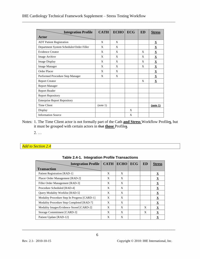
Table 2.3-1. Integration Profile Actors
Integration Profile
Actor
CATH ECHO ECG ED Stress
Acquisition Modality X X X X
IHE Cardiology Technical Framework Supplement – Stress Testing Workflow
______________________________________________________________________________
______________________________________________________________________________
6
Rev. 2.1- 2010-10-15 Copyright © 2010: IHE International, Inc.
Integration Profile
Actor
CATH ECHO ECG ED Stress
ADT Patient Registration X X X
Department System Scheduler/Order Filler X X X
Evidence Creator X X X X
Image Archive X X X X
Image Display X X X X
Image Manager X X X X
Order Placer X X X
Performed Procedure Step Manager X X X
Report Creator X X
Report Manager
Report Reader
Report Repository
Enterprise Report Repository
Time Client (note 1) (note 1)
Display X
Information Source X
Notes: 1. The Time Client actor is not formally part of the Cath and Stress Workflow Profiles, but
it must be grouped with certain actors in that those Profiles.
2. …
Add to Section 2.4
Table 2.4-1. Integration Profile Transactions
Integration Profile
Transaction
CATH ECHO ECG ED Stress
Patient Registration [RAD-1] X X X
Placer Order Management [RAD-2] X X X
Filler Order Management [RAD-3] X X X
Procedure Scheduled [RAD-4] X X X
Query Modality Worklist [RAD-5] X X X
Modality Procedure Step In Progress [CARD-1] X X X
Modality Procedure Step Completed [RAD-7] X X X
Modality Images/Evidence Stored [CARD-2] X X X X
Storage Commitment [CARD-3] X X X X
Patient Update [RAD-12] X X X

IHE Cardiology Technical Framework Supplement – Stress Testing Workflow
______________________________________________________________________________
______________________________________________________________________________
7
Rev. 2.1- 2010-10-15 Copyright © 2010: IHE International, Inc.
Integration Profile
Transaction
CATH ECHO ECG ED Stress
Procedure Update [RAD-13] X X X
Query Images [RAD-14] X X X
Query Evidence Documents [RAD-44] X
Retrieve Images/Evidence [CARD-4] X X X
Instance Availability Notification [RAD-49] X X X
Maintain Time [ITI-1] (note 1) (note 1)
Retrieve Specific Info for Display [ITI-11] X
Retrieve ECG List [CARD-5] X
Retrieve ECG Document for Display [CARD-6] X
Encapsulated Report Submission [CARD-7]
Report Reference Submission [CARD-8]
Encapsulated Report Storage [CARD-9]
Encapsulated Report Query [CARD-10]
Encapsulated Report Retrieve [CARD-11]
Retrieve Document for Display [ITI-12]
Notes: 1. The Maintain Time transaction is not formally part of the Cath and Stress Workflow
Profiles, but it is required for the Time Client actor grouped with certain actors in that those
Profiles.
2. …
Add to Section 2.5
In general, a product implementation may incorporate any single actor or combination of actors.
However, in the cases specified below, the implementation of one actor requires the
implementation of one or more additional actors:
The Image Archive shall be grouped with the Image Manager, and the Image Manager shall be
grouped with the Image Archive.
The Image Manager participating in Cath, Workflow or Echo, or Stress Workflow Integration
Profiles shall be grouped with a Performed Procedure Step Manager. The grouped Performed
Procedure Step Manager shall be capable of being disabled via configuration.
The Department System Scheduler/Order Filler participating in Cath, Workflow or Echo, or
Stress Workflow shall be grouped with a Performed Procedure Step Manager. The grouped
Performed Procedure Step Manager shall be capable of being disabled via configuration.
The DSS/Order Filler and Modality Acquisition Actors participating in Cath or Stress
Workflow Integration Profiles shall be grouped with the Time Client Actor of the Consistent
Time Profile.

IHE Cardiology Technical Framework Supplement – Stress Testing Workflow
______________________________________________________________________________
______________________________________________________________________________
8
Rev. 2.1- 2010-10-15 Copyright © 2010: IHE International, Inc.
Add new Section 8
8 Stress Testing Workflow (Stress)
The Stress Testing Workflow Integration Profile describes the workflow associated with cardiac
stress test procedures. This profile deals with patient identifiers, orders, scheduling, status
reporting, multi-stage exams, and data storage. It specifies the scheduling and coordination of
procedure data across a variety of imaging, ECG acquisition, measurement, and analysis systems,
and its reliable storage in an archive from where it is available to support subsequent workflow
steps, such as reporting.
This profile has much in common with the IHE Radiology Scheduled Workflow and Patient
Information Reconciliation Integration Profiles, but deals more explicitly with the multi-modality
coordination, and with stress-specific data requirements. See Rad TF-1: 3.4 for the integrated
workflow data model adopted by the IHE Technical Framework for HL7 messages and DICOM
information objects. This data model offers three major levels of control for workflow:
Order: A request for a Departmental Service
Requested Procedure: Unit of work resulting in one or more reports, with associated codified,
billable acts.
Scheduled and Performed Procedure Step: the smallest unit of work in the workflow that is
scheduled (work to do) or performed (work done).
A clear understanding of the workflow data model is essential to interpreting the Stress Profile.
Additional information may be found in Appendix B.
Although the major cases for stress testing workflow are described in the following subsections, it
is beneficial to also see the corresponding workflows in radiology. Rad TF-1: 3.3 has a description
of the “normal” scheduled workflow when all three levels of control in the data model are fully
utilized for known patients.
8.1 Actors/Transactions
Figure 8.1-1 diagrams the actors involved with this profile and the transactions between actors.
Note that this diagram maintains the actor and transaction names specified in the Radiology
Technical Framework (RAD-TF) for consistency of definitions. In particular, note that the Image
Manager / Image Archive and Image Display are required in this profile to support not just images,
but also waveforms and structured reports.

IHE Cardiology Technical Framework Supplement – Stress Testing Workflow
______________________________________________________________________________
______________________________________________________________________________
9
Rev. 2.1- 2010-10-15 Copyright © 2010: IHE International, Inc.
Pt. Registration [RAD-1] Patient Update [RAD-12]
Pt. Registration [RAD-1]
Patient Update [RAD-12]
Placer Order Management [RAD-2]Filler Order Management [RAD-3]
ADT
Query Images [RAD-14]
Retrieve Images/Evidence [CARD-4]
Image Display
Modality Image/Evidence
Stored [CARD-2]
Storage
Commitment
[CARD-3]
Procedure Scheduled [RAD-4]
Procedure Updated [RAD-13]
Query Modality Worklist [RAD-5]
Performed Procedure
Step Manager
Modality PS in Progress [CARD-1]Modality PS Completed [RAD-7]
Modality PS in Progress [CARD-1] Modality PS Completed [RAD-7]
Modality PS in Progress [CARD-1]Modality PS Completed [RAD-7]
Order Placer
Acquisition Modality
Image
Manager
Image
Archive
DSS/ Order Filler
Patient Update [RAD-12]
Modality Image/Evidence
Stored [CARD-2]
Storage
Commitment
[CARD-3]
Evidence
CreatorModality PS in Progress [CARD-1]Modality PS Completed [RAD-7]
Instance Availability Notification [RAD-49]
Report Creator
Report Creator
Time Client
Time Client
Figure 8.1-1. Stress Testing Workflow Diagram
Table 8.1-1 lists the transactions for each actor directly involved in the Stress Profile. In order to
claim support of this Integration Profile, an implementation must perform the required transactions
(labeled “R”). Transactions labeled “O” are optional. A complete list of options defined by this
Integration Profile that implementations may choose to support is listed in Section 8.2.
Table 8.1-1. Stress Workflow - Actors and Transactions
Actors Transactions Optionality Section
ADT Patient
Registration
Patient Registration [RAD-1] R RAD-TF 2: 4.1
Patient Update [RAD-12] R RAD-TF 2: 4.12
Order Placer Patient Registration [RAD-1] R RAD-TF 2: 4.1
Patient Update [RAD-12] R RAD-TF 2: 4.12
Placer Order Management [RAD-2] R RAD-TF 2: 4.2
Filler Order Management [RAD-3] R RAD-TF 2: 4.3
Department System
Scheduler/
Patient Registration [RAD-1] R RAD-TF 2: 4.1
Patient Update [RAD-12] R RAD-TF 2: 4.12

IHE Cardiology Technical Framework Supplement – Stress Testing Workflow
______________________________________________________________________________
______________________________________________________________________________
10
Rev. 2.1- 2010-10-15 Copyright © 2010: IHE International, Inc.
Actors Transactions Optionality Section
Order Filler
Placer Order Management [RAD-2] R RAD-TF 2: 4.2
Filler Order Management [RAD-3] R RAD-TF 2: 4.3
Procedure Scheduled [RAD-4] R RAD-TF 2: 4.4
Query Modality Worklist [RAD-5] R RAD-TF 2: 4.5
Modality Procedure Step In Progress [CARD-1] R CARD-TF 2: 4.1
Modality Procedure Step Completed [RAD-7] R RAD-TF 2: 4.7
Procedure Updated [RAD-13] R RAD-TF 2: 4.13
Instance Availability Notification [RAD-49] O RAD-TF 3: 4.49
Acquisition
Modality
Query Modality Worklist [RAD-5] R RAD-TF 2: 4.5
Modality Procedure Step In Progress [CARD-1] R CARD-TF 2: 4.1
Modality Procedure Step Completed [RAD-7] R RAD-TF 2: 4.7
Modality Images/Evidence Stored [CARD-2] R CARD-TF 2: 4.2
Storage Commitment [CARD-3] R CARD-TF 2: 4.3
Image Manager/
Image Archive
Procedure Scheduled [RAD-4] R RAD-TF 2: 4.4
Modality Procedure Step In Progress [CARD-1] R CARD-TF 2: 4.1
Modality Procedure Step Completed [RAD-7] R RAD-TF 2: 4.7
Modality Images/Evidence Stored [CARD-2] R CARD-TF 2: 4.2
Storage Commitment [CARD-3] R CARD-TF 2: 4.3
Patient Update [RAD-12] R RAD-TF 2: 4.12
Procedure Updated [RAD-13] R RAD-TF 2: 4.13
Query Images [RAD-14] R RAD-TF 2: 4.14
Retrieve Images/Evidence [CARD-4] R CARD-TF 2: 4.4
Instance Availability Notification [RAD-49] O RAD-TF 3: 4.49
Performed
Procedure Step
Manager
Modality Procedure Step In Progress [CARD-1] R CARD-TF 2: 4.1
Modality Procedure Step Completed [RAD-7] R RAD-TF 2: 4.7
Image Display Query Images [RAD-14] R RAD-TF 2: 4.14
Retrieve Images/Evidence [CARD-4] R CARD-TF 2: 4.4
Evidence Creator Modality Procedure Step In Progress [CARD-1] R CARD-TF 2: 4.1
Modality Procedure Step Completed [RAD-7] R RAD-TF 2: 4.7
Modality Images/Evidence Stored [CARD-2] R CARD-TF 2: 4.2
Storage Commitment [CARD-3] R CARD-TF 2: 4.3
Report Creator (See Text)
Refer to Table 2-1 for other profiles that may be pre-requisites for this profile.
If a Report Creator wishes to participate in this profile, it does not have to support any transactions
directly, however it is required to be grouped either with an Acquisition Modality, or with an
Image Display. This grouping enables the Report Creator to have access to the images, waveforms,

IHE Cardiology Technical Framework Supplement – Stress Testing Workflow
______________________________________________________________________________
______________________________________________________________________________
11
Rev. 2.1- 2010-10-15 Copyright © 2010: IHE International, Inc.
and evidence documents of the Requested Procedure. The Report Creator shall be able to reference
or transfer some contents of the created or retrieved objects into the reports it creates, and to send
those reports in accordance with another Profile.
Notes: 1. See, e.g., Report Creator in the DRPT Profile.
2. In accordance with section 2.5, there are no external transactions for the Report Creator in
this Profile. Interactions with the grouped Acquisition Modality or Image Display actor use
internal mechanisms beyond the scope of the Technical Framework.
8.2 Stress Workflow Integration Profile Options
Many Actors have Options defined in order to accommodate variations in use across domains or
implementations. Options that may be selected for this Integration Profile are listed in the table
8.2-1 along with the Actors to which they apply. Certain of these Options are required for
implementation by actors in this Profile (although they may be truly optional in other Profiles).
Table 8.2-1: Stress Workflow - Actors and Options
Actor Option Name Optionality Vol & Section
ADT Patient Registration No options defined - -
Order Placer No options defined - -
Department System Scheduler/Order
Filler
Multi-modality Procedure Update R CARD-TF 2: 4.1
PPS Exception Management O RAD-TF 2: 4.7
Availability of PPS-Referenced Instances O RAD-TF 3: 4.49
Acquisition Modality Patient Based Worklist Query O RAD-TF 2: 4.5
Broad Worklist Query R (see note 1) RAD-TF 2: 4.5
PPS Exception Management O RAD-TF 2: 4.7
Stress ECG R (see note 2) CARD-TF 2: 4.2
Stress Echo R (see note 2) CARD-TF 2: 4.2
Nuclear Medicine (see note 3) R (see note 2) RAD-TF 2: 4.8
Image Manager/ Image Archive PPS Exception Management O RAD-TF 2: 4.7
Intermittently Connected Modality R CARD-TF 2: 4.3
Stress ECG R CARD-TF 2: 4.2
Echocardiography R CARD-TF 2: 4.2
Nuclear Medicine (see note 3) R RAD-TF 2: 4.8
Availability of PPS-Referenced Instances O RAD-TF 3: 4.49
Image Display Stress ECG R CARD-TF 2: 4.4
Stress Echo R CARD-TF 2: 4.4
Cardiac NM (see notes 3, 4) R RAD-TF 2: 4.16
Performed Procedure Step Manager No options defined - -

IHE Cardiology Technical Framework Supplement – Stress Testing Workflow
______________________________________________________________________________
______________________________________________________________________________
12
Rev. 2.1- 2010-10-15 Copyright © 2010: IHE International, Inc.
Actor Option Name Optionality Vol & Section
Evidence Creator No options defined - -
Report Creator No options defined - -
Note 1: The Broad Worklist Query option facilitates effective workflow in the multimodality
environment.
Note 2: An Acquisition Modality shall support one of the options Stress ECG, Stress Echo, or Nuclear
Medicine.
Note 3: Nuclear Medicine (NM) is not formally an option, but is rather a separate IHE Profile. The
Image Manager/Image Archive and the Image Display must support the NM Profile.
Note 4: The Image Display shall support the Cardiac NM Option of the NM Profile.
8.3 Stress Testing Scheduled Process Flow
The process and information flow for Stress Test procedures generally follows the same flow as
the Cath Scheduled Process Flow (see section 3.3).
8.4 Stress Testing Workflow Use Cases
Stress tests are performed to challenge the patient’s cardiovascular system in a controlled stress-
inducing environment.
A stress test is ordered by a physician, either inside the performing institution, or by a referral from
outside the institution. The test is scheduled for the patient, transportation is arranged if the patient
is an inpatient, equipment is scheduled, radiopharmaceuticals are ordered if the stress test is
included with nuclear imaging, a room is reserved for the test, and personnel are scheduled. The
test is performed by a physician or trained professional (such as a nurse, physician’s assistant, or
trained exercise technician).
In order to stress the patient, a stress test commonly uses an exercise device such as a treadmill or
bicycle ergometer. Other types of stress agents are pharmacologic and metabolic. Regardless of the
stress method, the Stress Monitor measures the stress study time, obtains electrocardiograms at
discrete intervals, and reports out the performance of the patient’s cardiovascular activity at each
stage of work. The end point of the study is determined by a physician, or trained allied health
individual, and then interpreted.
Stress testing is performed alone, or in conjunction with an imaging protocol such as a thallium
nuclear cardiology study, or stress echocardiography. The management of the test must take into
account all potential modalities.
8.4.1 Use Case S1: Cardiac Stress Test, ECG Only
A cardiac stress test is performed based on a prescribed exercise or pharmacological stress
protocol. This protocol is divided into stages of stress, where typical stages are Resting, Baseline,
Stage 1, Stage 2,…, Recovery. The patient is subjected to increasing levels of stress for each stage
IHE Cardiology Technical Framework Supplement – Stress Testing Workflow
______________________________________________________________________________
______________________________________________________________________________
13
Rev. 2.1- 2010-10-15 Copyright © 2010: IHE International, Inc.
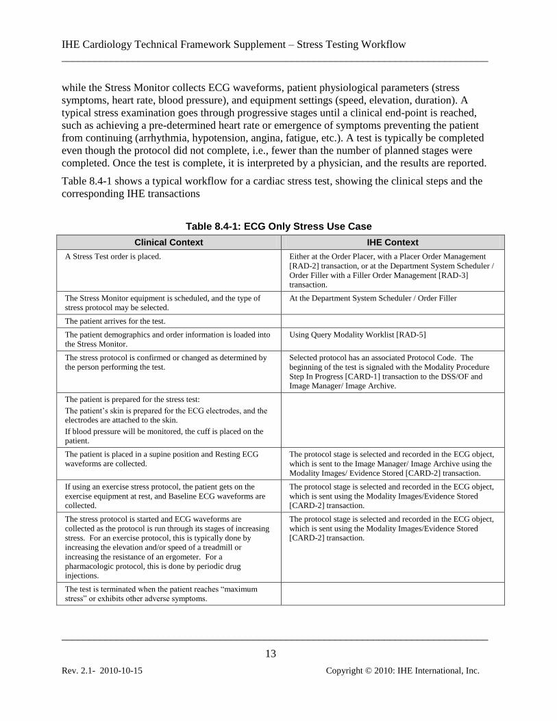
while the Stress Monitor collects ECG waveforms, patient physiological parameters (stress
symptoms, heart rate, blood pressure), and equipment settings (speed, elevation, duration). A
typical stress examination goes through progressive stages until a clinical end-point is reached,
such as achieving a pre-determined heart rate or emergence of symptoms preventing the patient
from continuing (arrhythmia, hypotension, angina, fatigue, etc.). A test is typically be completed
even though the protocol did not complete, i.e., fewer than the number of planned stages were
completed. Once the test is complete, it is interpreted by a physician, and the results are reported.
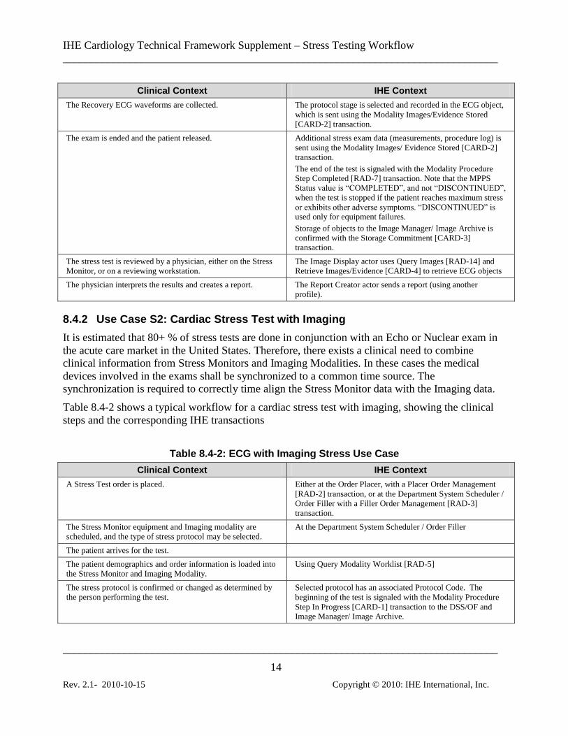
Table 8.4-1 shows a typical workflow for a cardiac stress test, showing the clinical steps and the
corresponding IHE transactions
Table 8.4-1: ECG Only Stress Use Case
Clinical Context IHE Context
A Stress Test order is placed. Either at the Order Placer, with a Placer Order Management
[RAD-2] transaction, or at the Department System Scheduler /
Order Filler with a Filler Order Management [RAD-3] transaction.
The Stress Monitor equipment is scheduled, and the type of
stress protocol may be selected.
At the Department System Scheduler / Order Filler
The patient arrives for the test.
The patient demographics and order information is loaded into
the Stress Monitor.
Using Query Modality Worklist [RAD-5]
The stress protocol is confirmed or changed as determined by
the person performing the test.
Selected protocol has an associated Protocol Code. The
beginning of the test is signaled with the Modality Procedure
Step In Progress [CARD-1] transaction to the DSS/OF and Image Manager/ Image Archive.
The patient is prepared for the stress test:
The patient’s skin is prepared for the ECG electrodes, and the electrodes are attached to the skin.
If blood pressure will be monitored, the cuff is placed on the patient.
The patient is placed in a supine position and Resting ECG
waveforms are collected.
The protocol stage is selected and recorded in the ECG object,
which is sent to the Image Manager/ Image Archive using the
Modality Images/ Evidence Stored [CARD-2] transaction.
If using an exercise stress protocol, the patient gets on the
exercise equipment at rest, and Baseline ECG waveforms are collected.
The protocol stage is selected and recorded in the ECG object,
which is sent using the Modality Images/Evidence Stored [CARD-2] transaction.
The stress protocol is started and ECG waveforms are
collected as the protocol is run through its stages of increasing
stress. For an exercise protocol, this is typically done by
increasing the elevation and/or speed of a treadmill or
increasing the resistance of an ergometer. For a
pharmacologic protocol, this is done by periodic drug injections.
The protocol stage is selected and recorded in the ECG object,
which is sent using the Modality Images/Evidence Stored [CARD-2] transaction.
The test is terminated when the patient reaches “maximum
stress” or exhibits other adverse symptoms.
IHE Cardiology Technical Framework Supplement – Stress Testing Workflow
______________________________________________________________________________
______________________________________________________________________________
14
Rev. 2.1- 2010-10-15 Copyright © 2010: IHE International, Inc.
Clinical Context IHE Context
The Recovery ECG waveforms are collected. The protocol stage is selected and recorded in the ECG object,
which is sent using the Modality Images/Evidence Stored
[CARD-2] transaction.
The exam is ended and the patient released. Additional stress exam data (measurements, procedure log) is
sent using the Modality Images/ Evidence Stored [CARD-2] transaction.
The end of the test is signaled with the Modality Procedure
Step Completed [RAD-7] transaction. Note that the MPPS
Status value is “COMPLETED”, and not “DISCONTINUED”,
when the test is stopped if the patient reaches maximum stress
or exhibits other adverse symptoms. “DISCONTINUED” is used only for equipment failures.
Storage of objects to the Image Manager/ Image Archive is
confirmed with the Storage Commitment [CARD-3]
transaction.
The stress test is reviewed by a physician, either on the Stress
Monitor, or on a reviewing workstation.
The Image Display actor uses Query Images [RAD-14] and
Retrieve Images/Evidence [CARD-4] to retrieve ECG objects
The physician interprets the results and creates a report. The Report Creator actor sends a report (using another
profile).
8.4.2 Use Case S2: Cardiac Stress Test with Imaging
It is estimated that 80+ % of stress tests are done in conjunction with an Echo or Nuclear exam in
the acute care market in the United States. Therefore, there exists a clinical need to combine
clinical information from Stress Monitors and Imaging Modalities. In these cases the medical
devices involved in the exams shall be synchronized to a common time source. The
synchronization is required to correctly time align the Stress Monitor data with the Imaging data.
Table 8.4-2 shows a typical workflow for a cardiac stress test with imaging, showing the clinical
steps and the corresponding IHE transactions
Table 8.4-2: ECG with Imaging Stress Use Case
Clinical Context IHE Context
A Stress Test order is placed. Either at the Order Placer, with a Placer Order Management
[RAD-2] transaction, or at the Department System Scheduler /
Order Filler with a Filler Order Management [RAD-3]
transaction.
The Stress Monitor equipment and Imaging modality are
scheduled, and the type of stress protocol may be selected.
At the Department System Scheduler / Order Filler
The patient arrives for the test.
The patient demographics and order information is loaded into
the Stress Monitor and Imaging Modality.
Using Query Modality Worklist [RAD-5]
The stress protocol is confirmed or changed as determined by
the person performing the test.
Selected protocol has an associated Protocol Code. The
beginning of the test is signaled with the Modality Procedure
Step In Progress [CARD-1] transaction to the DSS/OF and Image Manager/ Image Archive.

IHE Cardiology Technical Framework Supplement – Stress Testing Workflow
______________________________________________________________________________
______________________________________________________________________________
15
Rev. 2.1- 2010-10-15 Copyright © 2010: IHE International, Inc.
Clinical Context IHE Context
The ECG waveform analog output from the Stress Monitor is
connected to the Imaging Modality. This analog output
provides a cardiac gating signal for the collection of cardiac images.
The patient is prepared for the stress test:
The patient’s skin is prepared for the ECG electrodes, and the electrodes are attached to the skin.
If blood pressure will be monitored, the cuff is placed on the patient.
The patient is placed in a supine position and Resting ECG
waveforms are collected.
The protocol stage is selected and recorded in the ECG object,
which is sent to the Image Manager/ Image Archive using the Modality Images/ Evidence Stored [CARD-2] transaction.
Resting, pre-stress images are collected. The protocol stage is selected and recorded in the image
object, which is sent to the Image Manager/ Image Archive
using the Modality Images/ Evidence Stored [CARD-2]
transaction.
If using an exercise stress protocol, the patient gets on the
exercise equipment at rest, and Baseline ECG waveforms are collected.
The protocol stage is selected and recorded in the ECG object,
which is sent using the Modality Images/Evidence Stored [CARD-2] transaction.
The stress protocol is started and ECG waveforms are
collected as the protocol is run through its stages of increasing
stress. For an exercise protocol, this is typically done by
increasing the elevation and/or speed of a treadmill or
increasing the resistance of an ergometer. For a
pharmacologic protocol, this is done by periodic drug injections.
The protocol stage is selected and recorded in the ECG object,
which is sent using the Modality Images/Evidence Stored [CARD-2] transaction.
Mid-stress images are collected as needed. For an exercise
protocol, the patient steps off the treadmill or ergometer for the imaging process.
The protocol stage is selected and recorded in the image
object, which is sent to the Image Manager/ Image Archive
using the Modality Images/ Evidence Stored [CARD-2]
transaction.
The test is terminated when the patient reaches “maximum stress” or exhibits other adverse symptoms.
Peak stress images are collected. The protocol stage is selected and recorded in the image
object, which is sent to the Image Manager/ Image Archive
using the Modality Images/ Evidence Stored [CARD-2] transaction.
The Recovery ECG waveforms are collected. The protocol stage is selected and recorded in the ECG object,
which is sent using the Modality Images/Evidence Stored [CARD-2] transaction.
The exam is ended and the patient released. Additional stress exam data (measurements, procedure log) is
sent using the Modality Images/ Evidence Stored [CARD-2] transaction.
The end of the test is signaled with the Modality Procedure
Step Completed [RAD-7] transaction.
Storage of objects to the Image Manager/ Image Archive is
confirmed with the Storage Commitment [CARD-3] transaction.
The stress test is reviewed by a physician, either on the Stress
Monitor, or on a reviewing workstation.
The Image Display actor uses Query Images [RAD-14] and
Retrieve Images/Evidence [CARD-4] to retrieve ECG, image,
IHE Cardiology Technical Framework Supplement – Stress Testing Workflow
______________________________________________________________________________
______________________________________________________________________________
16
Rev. 2.1- 2010-10-15 Copyright © 2010: IHE International, Inc.
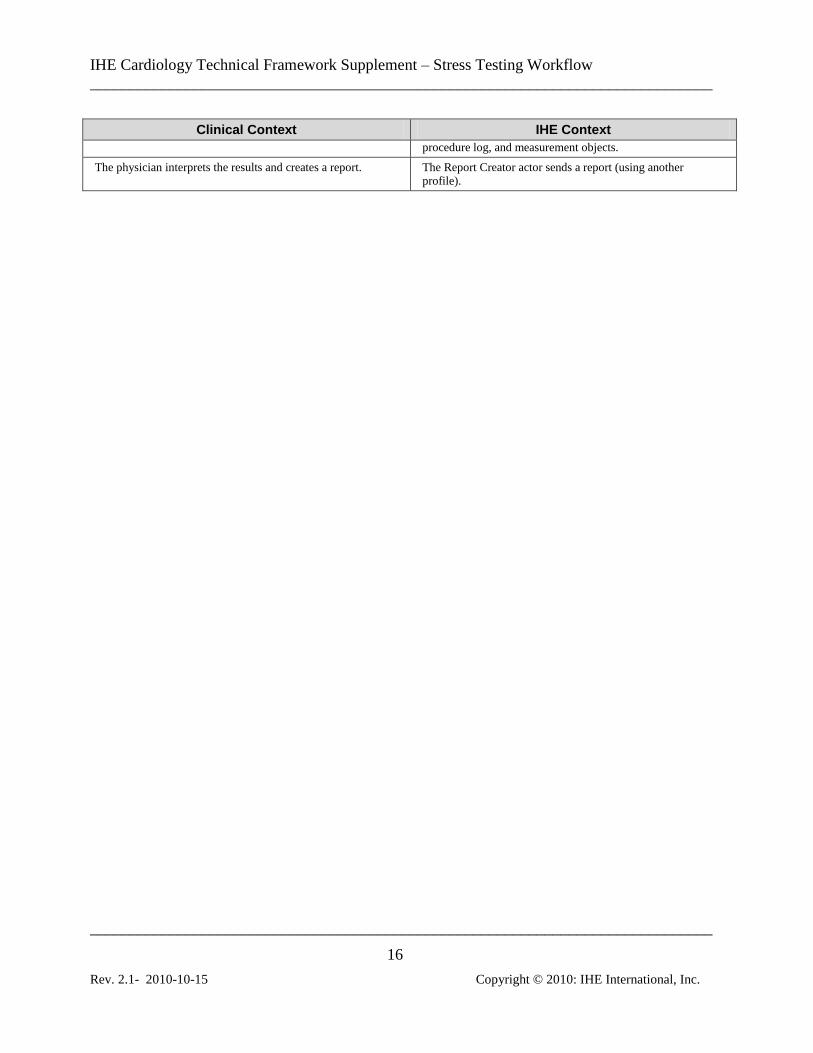
Clinical Context IHE Context
procedure log, and measurement objects.
The physician interprets the results and creates a report. The Report Creator actor sends a report (using another profile).

IHE Cardiology Technical Framework Supplement – Stress Testing Workflow
______________________________________________________________________________
______________________________________________________________________________
17
Rev. 2.1- 2010-10-15 Copyright © 2010: IHE International, Inc.
Changes to Volume 2 - Transactions Add to Section 4.2
4.2 Modality Images/Evidence Stored [CARD-2]
...
4.2.6 Stress ECG Option
Image Archives supporting the STRESS ECG option are required to support all of the SOP classes
listed in Table 4.2-1 below.
Table 4.2-10. Stress ECG SOP Classes
SOP Class UID SOP Class Name
1.2.840.10008.5.1.4.1.1.9.1.1 12-Lead ECG Waveform Storage
1.2.840.10008.5.1.4.1.1.9.1.2 General ECG Waveform Storage
1.2.840.10008.5.1.4.1.1.88.22 Enhanced SR
1.2.840.10008.5.1.4.1.1.88.33 Comprehensive SR
1.2.840.10008.5.1.4.1.1.88.40 Procedure Log
1.2.840.10008.5.1.4.1.1.104.1 Encapsulated PDF
Acquisition Modality actors supporting the STRESS ECG option are required to support a number
of attributes in ECG Waveform objects created for a stress procedure as described in Table 4.2-11.
Many of these requirements build on attributes which are Type 2 or Type 3 in DICOM (such
attributes are indicated with R+).
Table 4.2-11. Attributes That Convey Staged Protocol Related Information
Attribute Name Tag Requirement
Performed Procedure Step Description (0040,0254) R+
Protocol Name (0018,1030) R+
Performed Protocol Code Sequence (0040,0260) R+
Acquisition Context Sequence (0040,0555) R+
The Performed Protocol Code Sequence for stress test procedures shall use codes drawn from the
subset of DICOM Context Group 3261 shown in Table 4.2-12.

IHE Cardiology Technical Framework Supplement – Stress Testing Workflow
______________________________________________________________________________
______________________________________________________________________________
18
Rev. 2.1- 2010-10-15 Copyright © 2010: IHE International, Inc.
Table 4.2-12. ECG Stress Protocol Codes
Coding Scheme Designator (0008,0102)
Code Value (0008,0100)
Code Meaning (0008,0104)
SRT P2-7131C Balke protocol
SRT P2-7131A Bruce protocol
SRT P2-7131D Ellestad protocol
SRT P2-7131B Modified Bruce protocol
SRT P2-713A1 Modified Naughton protocol
SRT P2-713A0 Naughton protocol
SRT P2-7131F Pepper protocol
SRT P2-7131E Ramp protocol
SRT P2-31102 Bicycle Ergometer Stress Test protocol
SRT P2-31107 Pharmacologic Stress protocol
SRT P2-3110A Dipyridamole Stress protocol
SRT P2-31109 Adenosine Stress protocol
SRT P2-31108 Dobutamine Stress protocol
Adapted from DICOM PS3.16-2009
Note: The pharmacologic stress protocol concepts have been submitted to SNOMED for assignment
of codes. Such codes are expected to be available at the time of adoption of Final Text for this
Transaction.
The Acquisition Context Sequence shall include at least the two content items shown in Table 4.2-
13, drawn from DICOM Template 3401, and use the codes from DICOM Context Group 3262
shown in Table 4.2-14.
Table 4.2-13. Acquisition Context Items
Value Type
Concept Code Value
CODE (109054, DCM, ”Patient State”) See Table 4.2-14
NUM (109055, DCM, ”Protocol Stage”) Numeric Value, Units of Measurement is (“{stage}”, UCUM, “stage”)
Adapted from DICOM PS3.16-2009
Table 4.2-14. Patient State Codes
Coding Scheme Designator (0008,0102)
Code Value (0008,0100)
Code Meaning (0008,0104)
SRT F-01604 Resting state
SRT F-01602 Baseline state
IHE Cardiology Technical Framework Supplement – Stress Testing Workflow
______________________________________________________________________________
______________________________________________________________________________
19
Rev. 2.1- 2010-10-15 Copyright © 2010: IHE International, Inc.
Coding Scheme Designator (0008,0102)
Code Value (0008,0100)
Code Meaning (0008,0104)
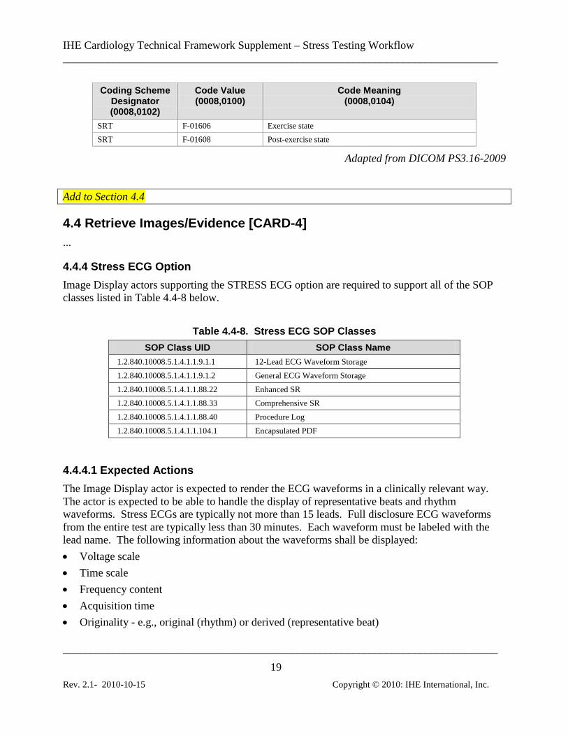
SRT F-01606 Exercise state
SRT F-01608 Post-exercise state
Adapted from DICOM PS3.16-2009
Add to Section 4.4
4.4 Retrieve Images/Evidence [CARD-4]
...
4.4.4 Stress ECG Option
Image Display actors supporting the STRESS ECG option are required to support all of the SOP
classes listed in Table 4.4-8 below.
Table 4.4-8. Stress ECG SOP Classes
SOP Class UID SOP Class Name
1.2.840.10008.5.1.4.1.1.9.1.1 12-Lead ECG Waveform Storage
1.2.840.10008.5.1.4.1.1.9.1.2 General ECG Waveform Storage
1.2.840.10008.5.1.4.1.1.88.22 Enhanced SR
1.2.840.10008.5.1.4.1.1.88.33 Comprehensive SR
1.2.840.10008.5.1.4.1.1.88.40 Procedure Log
1.2.840.10008.5.1.4.1.1.104.1 Encapsulated PDF
4.4.4.1 Expected Actions
The Image Display actor is expected to render the ECG waveforms in a clinically relevant way.
The actor is expected to be able to handle the display of representative beats and rhythm
waveforms. Stress ECGs are typically not more than 15 leads. Full disclosure ECG waveforms
from the entire test are typically less than 30 minutes. Each waveform must be labeled with the
lead name. The following information about the waveforms shall be displayed:
Voltage scale
Time scale
Frequency content
Acquisition time
Originality - e.g., original (rhythm) or derived (representative beat)
IHE Cardiology Technical Framework Supplement – Stress Testing Workflow
______________________________________________________________________________
______________________________________________________________________________
20
Rev. 2.1- 2010-10-15 Copyright © 2010: IHE International, Inc.
Protocol name, protocol stage, and patient state.
The Image Display actor shall support the display of DICOM Encapsulated PDF and DICOM SR
SOP Instances.
Note: An Image Display that supports a DICOM SR SOP Class is required (by the DICOM
Standard) to unambiguously render all legal SOP Instances within that SOP Class, regardless
of the Template used to create it. See DICOM PS3.4 Annex O.

IHE Cardiology Technical Framework Supplement – Stress Testing Workflow
______________________________________________________________________________
______________________________________________________________________________
21
Rev. 2.1- 2010-10-15 Copyright © 2010: IHE International, Inc.
Add new Appendix
Appendix X: Stress Test Protocol and Stage Identification
For various historical and clinical reasons, the manner in which stress test protocols and protocol
stages are identified differs across the modality information object definitions. This appendix
elucidates the requirements for such identification.
X.1 Procedure
In stress testing, the selection of the protocol is first constrained by the selection of the type of
stress test procedure, i.e., the modality or modalities to be used (stress ECG alone, ECG plus echo
or nuclear imaging, or imaging alone), and the selection of the stress induction method (exercise or
pharmacological). This top level procedure type selection must be done at test scheduling time in
order to marshal the necessary resources for the test, and is conveyed in the Requested Procedure
Code Sequence.
X.2 Protocol
Within the Requested Procedure, the specific protocol is selected. Typically this is done at the
acquisition equipment when the test is set up. However, it can also be specified (or recommended)
during scheduling. In the DICOM information model, this protocol is a modality-dependent
construct associated with the scheduled and performed procedure steps.
As a modality-dependent construct, there is no need for the protocol to be identical between the
ECG and imaging modalities. In fact, the ECG modality may have a deeper understanding of the
range of such protocols than the imaging modalities. The clinical requirement is for each modality
to encode its acquired data with sufficient information about the protocol so as to be able to
interpret the data.
When the protocol is selected during scheduling, its coded representation is passed to the
modalities in the Scheduled Protocol Code Sequence attribute. The protocol actually used by the
modality (which may differ from the scheduled protocol) is reported in the Performed Protocol
Code Sequence attribute of the composite object and the Modality Performed Procedure Step
object. The required values for this attribute are enumerated in table 4.2-3 for Echo and in table
4.2-12 for ECG. It is recommended that NM use the values in 4.2-12.
Note that the ECG Acquisition Context Template 3401 used in Stress ECG Waveform objects
allows encoding of the protocol in the Acquisition Context Sequence attribute, but that use is
deprecated by IHE in favor of the Performed Protocol Code Sequence attribute.
X.3 Stage
Stress protocols typically have a series of stages. These stages typically increase the level of
stress. Each stage is defined by the protocol and is identified by a number. For example, the
Bruce protocol has 7 stages of work identified as stages 1, 2, 3, 4, 5, 6 and 7. Stage 1 has a

IHE Cardiology Technical Framework Supplement – Stress Testing Workflow
______________________________________________________________________________
______________________________________________________________________________
22
Rev. 2.1- 2010-10-15 Copyright © 2010: IHE International, Inc.
treadmill speed of 1.7 mph with a 10% grade and stage 7 has a speed of 6.0 mph with a 22% grade.
These protocol stage identifiers are recorded with the ECG waveforms in the Acquisition Context
Sequence.
The state of the patient relative to the overall test regimen is recorded in the Acquisition Context
Sequence of ECG and NM objects as “Patient State”. These coded states are enumerated in table
4.2-14.
The echocardiography modality also records the patient state using the attribute Stage Code
Sequence. These codes are enumerated in table 4.2-4 and convey similar concepts to those in table
4.2-14. Echocardiography similarly identifies for grouping purposes all images acquired in a
particular patient state using a numeric value denoted “Stage Number”. This “Stage Number”
should not be confused with the protocol stage number; it is a sequencing number meaningful only
to the echo modality.
X.4 Attribute Summary
A summary of the attributes used for protocol and stage identification is show in Table X-1.
Table X-1. Stress Protocol and Stage Concepts and Attributes
Concept Modality Worklist Echo ECG NM
Requested
Procedure
Requested Procedure Code
Sequence (0032,1064)
Procedure Code
Sequence (0008,1032)
Procedure Code
Sequence (0008,1032)
Procedure Code
Sequence (0008,1032)
Protocol Scheduled Protocol Code
Sequence (0040,0008)
Performed Protocol
Code Sequence (0040,0260)
CID 12001*
Performed Protocol
Code Sequence (0040,0260)
CID 3261
Performed Protocol
Code Sequence (0040,0260)
CID 3261**
Protocol
Stage Number
Acquisition Context
Sequence (0040,0555)
>(109055, DCM, “Protocol Stage”)
Patient State Stage Number
(0008,2122)
Stage Code Sequence
(0040,000A)
CID 12002
Acquisition Context
Sequence (0040,0555)
>(109054, DCM, “Patient State”)
CID 3262
Acquisition Context
Sequence (0040,0555)
>(109054, DCM, “Patient State”)
CID 3101
* Context Group 12001 includes by reference CID 3261, so that the Performed Protocol Code is
consistent across all modalities.
** Recommended.