
IFEN’s integrated (GNSS, foot-mounted IMU and QR … for supporting fire fighters Johannes Gruber,...
10
IFEN’s integrated (GNSS, foot-mounted IMU and QR codes) navigation device applied for supporting fire fighters Johannes Gruber, Wolfgang Bär, Eckart Göhler, Ilya Kroll, Thomas Pany, Jon Winkel IFEN GmbH, Alte Gruber Straße 6, 85586 Poing, Germany mail: [email protected] Abstract In the course of this paper, a by IFEN GmbH developed integrated navigation device for aiding and rescuing fire fighters in emergency situations is presented. In areas with sufficient signal strength the respective rescue force is tracked by means of GNSS/INS position information, whereas indoor or in areas without GNSS support, the positioning is conducted by means of a foot mounted inertial measurement unit and the according strap-down architecture. As an improving measure, the conducted strap-down algorithm was also supported by the introduction of so called ZUPT´s (Zero Velocity Updates) to stabilize the inertial navigation system. For recalibration issues, QR codes providing the system with WGS84 position information were placed at specific strategic points within buildings. Finally the separate navigation results were integrated by means of a Helmert Transformation, to obtain the fire fighters position in WGS84 coordinates. I. BIOGRAPHIES Johannes Gruber has received his Bachelor of Science in Engineering from the University of Applied Sciences in Graz. In his previous studies and projects he enhanced his knowledge in the field of avionics, flight control and integrated navigation systems. In close cooperation with the University of applied science he also works for IFEN GmbH Germany, especially focused on sensor data fusion technologies and integration architectures. Dr. Wolfgang Bär works for IFEN GmbH as a system engineer in the mobile solutions department. In particular, he is concerned with software development in the field of geo informatics, receiver user interface as well as usage of positioning in mobile applications. Dr. Eckart Göhler received his Diploma in physics from the University Tübingen in 1999. He finished the PhD in 2004 at the Institute for Astronomy and Astrophysics, Tübingen. Today he is working as a system engineer for GNSS receiver R&D at IFEN GmbH. Ilya Krol received his Diploma in Radioelectronic Systems from the Moscow Aviation Institute (MAI) in the year 2006. He is currently working for IFEN GmbH as a System FW Engineer. Dr. Thomas Pany works for IFEN GmbH as a senior research engineer in the GNSS receiver department. In particular, he is concerned with algorithm development and C/C++/assembler coding strategies. He also works as a lecturer at the University FAF Munich and the University of Applied Sciences Graz. His research interests include GNSS receivers, GNSS/INS integration, signal processing and GNSS science. Dr. Jón Ó. Winkel is head of receiver technology at IFEN GmbH since 2001. He studied physics at the universities in Hamburg and Regensburg. He received a PhD (Dr.-Ing.) from the University of the FAF in Munich in 2003 on GNSS modeling and simulations. II. INTRODUCTION In emergency situations search and rescue forces play a key role in saving lives and preventing the affected population from potential hazards. But in the worst case scenario also these first aiders need help. So for example knowledge about the location of a helpless firefighter in a burning building facilitates a potential rescue operation tremendously. Therefore in the frame of the INDOOR project at IFEN GmbH such a seamless indoor/outdoor navigation system for search and rescue forces was developed. The positioning part of the system is based on a two-frequency GPS/Galileo ASIC receiver providing high sensitivity GNSS positioning for outdoor as well as for roofed areas. For the seamless
Transcript of IFEN’s integrated (GNSS, foot-mounted IMU and QR … for supporting fire fighters Johannes Gruber,...
IFEN’s integrated (GNSS, foot-mounted IMU and QR codes) navigation device
applied for supporting fire fighters Johannes Gruber, Wolfgang Bär, Eckart Göhler, Ilya Kroll, Thomas Pany, Jon Winkel
IFEN GmbH, Alte Gruber Straße 6, 85586 Poing, Germany
mail: [email protected]
Abstract
In the course of this paper, a by IFEN GmbH developed integrated navigation device for aiding and rescuing fire fighters in emergency situations is presented. In areas with sufficient signal strength the respective rescue force is tracked by means of GNSS/INS position information, whereas indoor or in areas without GNSS support, the positioning is conducted by means of a foot mounted inertial measurement unit and the according strap-down architecture. As an improving measure, the conducted strap-down algorithm was also supported by the introduction of so called ZUPT´s (Zero Velocity Updates) to stabilize the inertial navigation system. For recalibration issues, QR codes providing the system with WGS84 position information were placed at specific strategic points within buildings. Finally the separate navigation results were integrated by means of a Helmert Transformation, to obtain the fire fighters position in WGS84 coordinates.
I. BIOGRAPHIES
Johannes Gruber has received his Bachelor of Science in Engineering from the University of Applied Sciences in Graz. In his previous studies and projects he enhanced his knowledge in the field of avionics, flight control and integrated navigation systems. In close cooperation with the University of applied science he also works for IFEN GmbH Germany, especially focused on sensor data fusion technologies and integration architectures.
Dr. Wolfgang Bär works for IFEN GmbH as a system engineer in the mobile solutions department. In particular, he is concerned with software development in the field of geo informatics, receiver user interface as well as usage of positioning in mobile applications.
Dr. Eckart Göhler received his Diploma in physics from the University Tübingen in 1999. He finished the
PhD in 2004 at the Institute for Astronomy and Astrophysics, Tübingen. Today he is working as a system engineer for GNSS receiver R&D at IFEN GmbH.
Ilya Krol received his Diploma in Radioelectronic Systems from the Moscow Aviation Institute (MAI) in the year 2006. He is currently working for IFEN GmbH as a System FW Engineer.
Dr. Thomas Pany works for IFEN GmbH as a senior research engineer in the GNSS receiver department. In particular, he is concerned with algorithm development and C/C++/assembler coding strategies. He also works as a lecturer at the University FAF Munich and the University of Applied Sciences Graz. His research interests include GNSS receivers, GNSS/INS integration, signal processing and GNSS science.
Dr. Jón Ó. Winkel is head of receiver technology at IFEN GmbH since 2001. He studied physics at the universities in Hamburg and Regensburg. He received a PhD (Dr.-Ing.) from the University of the FAF in Munich in 2003 on GNSS modeling and simulations.
II. INTRODUCTION
In emergency situations search and rescue forces play a key role in saving lives and preventing the affected population from potential hazards. But in the worst case scenario also these first aiders need help. So for example knowledge about the location of a helpless firefighter in a burning building facilitates a potential rescue operation tremendously.
Therefore in the frame of the INDOOR project at IFEN GmbH such a seamless indoor/outdoor navigation system for search and rescue forces was developed. The positioning part of the system is based on a two-frequency GPS/Galileo ASIC receiver providing high sensitivity GNSS positioning for outdoor as well as for roofed areas. For the seamless

positioning into indoor areas a foot-mounted IMU algorithm was developed in combination with the usage of QR code reference points placed at very few strategic points of the rescue forces. The human interface of the system consists of a rugged terminal device with a thermal camera system and a 3D building visualization for indoor navigation with the resulting position (visible for the firefighter and the commander). The system was demonstrated in Nov. 2012 for the German DLR by the airport firefighters of the Munich international airport. The demonstration scenario presented was a missing person search taken place at the airport facilities in a typical airport building via two floors with gates, passenger areas and luggage bands. Most navigation components of the system, the GNSS chip, QR codes usage and GNSS/QR/IMU integration algorithm were developed by IFEN as well as the system integration including housing.
The present paper will describe the system components in detail and provide some insights to the problems arisen from the restricted measurement scale of the MEMS IMU used. Furthermore, the use of the QR code readings to recalibrate the system as well as providing the needed acknowledgement messages for the firefighter is presented. Finally, results of the test trials and demonstration at the airport are presented.
The GPS/Galileo receiver used in this system to achieve the global alignment of the INS coordinate system is designed for poor signal conditions. It is equipped with a fast acquisition engine tailored for GPS/Galileo signals on L1/E1 and E5a/L5 plus a multi correlator tracking engine that can exploit the combined pilot/data Galileo signal structure. The navigation and tracking software on board of a powerful ARM processor allows to run long coherent integration by means of data wipe off from external assisted information and to compute position on single point up to position driven tracking feedback. In the frame of the INDOOR project a fast position had to be obtained in the partly obscured outdoor domains of the airport environment. For that, external assisted information was provided from a SUPL 2.0 server and was applied immediately for fast visibility determination and obtaining of precise positions which in turn are used by the IMU system.
For tracking issues in areas where GNSS position information was not sufficiently accurate (e.g. in buildings), the tracing of rescue forces was temporarily conducted by means of a foot mounted inertial navigation device. In use was a modern (10°/hour) MEMS inertial measurement unit (IMU, InterSense - NavChip) with a relatively broad range in terms of detectable gyro rates and accelerations which were essential for this type of application. A big benefit of this navigation technology is its standalone capability, which means that there is no need for external inputs to obtain a navigation solution. However, one of the main disadvantages in connection with inertial navigation architectures is that such systems suffer from integration drift. This means that small
acceleration and gyro rate errors (noise, biases) result in high velocity and consequently in even higher position errors, what makes it impossible to trace objects over a longer time span. A way to overcome this problem is the usage of so called zero velocity updates (ZUPTs). Thereby the available information of zero velocity during each stance phase was used, which made it inevitable to detect those rest periods during a walk. In the course of this, the measured angular velocities served as characteristic feature to distinguish between stance and stride. In this context also the exact mounting point of the sensor at the shoe was a decisive factor, since an unfavorable sensor location led to either insufficient long rest periods or caused tremendously high accelerations. In the worst occurring case, the recorded accelerations even exceeded the IMU´s detection limit of ±8g, which led to a loss of information, and hence to a result deterioration yielded by the strap-down equations.
For recalibration purposes of the IMU setup, a QR
code reader was coupled with the system providing encoded reference points with WGS84 coordinates as correction data. Special QR codes are placed at the entrance and exit of the building to signal the change from indoor to outdoor and otherwise. QR codes were used for the demonstration due to the ease of integration with the remaining system.
III. SYSTEM DESIGN
A. Application System Architectural Overview
The full system architecture for the demonstration at the Munich airport in november 2012 consisted of the following components:
• A rugged user terminal for the rescue forces equipped with a TETRA modem for data communication with the mission control. The terminal includes the GNSS receiver developed in the project and uses the positioning output by the inertial navigation algorithm.
• An external embedded device (Beagle Board) running the inertial navigation algorithm and communicating via Bluetooth with the rugged terminal. The IMU is connected via a USB cable to the embedded processing device
• A mission control center for guidance of the rescue personal by the chief in mission. It communicates with a database backend storing all the received and sent information and positions during a mission. The data can be used for later de-briefing and legal documentation of the mission.
• A SUPL 2.0 assistance server providing GPS and Galileo assistance data based on the SUPL 2.0 specification.

The demonstration took place in a no longer used part of the Munich airport. This building was used in the past as extension for the (at this time) crowded terminal 1. Now it is still equipped with luggage bands, waiting areas and gates and therefore provides a quite realistic demonstration venue. As mission scenario a missing person search was presented. After arrival the rescue forces were equipped with the rugged terminals and positioning equipment before proceeding with their rescue mission. Figure 1 shows a fire fighter with the equipment mounted.
Figure 1: Equipped fire fighter (left) and rugged terminal with QR reader attached (right)
B. Rugged Terminal
The rugged terminal was built by the project partner Andres Industries AG, Berlin. It encloses the high-sensitivity dual frequency GPS/Galileo receiver (by IFEN GmbH) and the dual frequency L1/L5 antenna (by IMST GmbH) developed in the frame of the INDOOR project. Furthermore it provides a thermal camera and TETRA short data service for communication.
The user interface of the terminals provides a 3D first person view of the building based on the position from either the GNSS receiver or the inertial navigation algorithm connected via Bluetooth. Furthermore the user interface automatically signals and displays received messages until the reception is confirmed. Sending of predefined messages is supported by simple finger control.
Figure 2: Rugged terminal with TETRA modem
C. Mission Control Center
The mission control center allows the administration of the whole mission including team composition. The user interface provides the current position of the teams in either a 3D building model or a 2D floor plan with different resolutions. Furthermore, the teams status like last transmission, transmission link quality, battery status and last sent command is displayed on a tree view. The operator can send and receive messages and send commands to the teams. The following figure shows the user interface of the mission control center with the 3D view in the upper right and the 2D view in the lower right part.
Figure 3: Mission control center user interface
IV. POSITIONING COMPONENTS
A. InTrack GPS/Galileo Chip
One of the cornerstones for the INDOOR project was the development of a GNSS receiver that could deal with heavily deteriorated signals. This InTrack GNSS receiver is capable to handle GPS and Galileo signals on two frequencies and to obtain a position fast with reasonable accuracy on code tracking. It consists

of an L1/L5 front end, a base band ASIC and an application processor. The base band ASIC (InTrack Chip) – that was a core development in the INDOOR project – is equipped with a fast acquisition engine that achieves a cold start search on all GPS or Galileo E1/E5a signals within seconds. Additionally it allows multi correlator tracking on 22 channels, combined for pilot/data on Galileo signals.
Though being a demonstrator only of a GNSS system, the InTrack receiver was designed to be useable in a mobile environment with limitations on power and size resources. It was built into a larger mobile terminal device with display and an IR camera that also established the communication with the IMU system (as shown in Figure 2).
Figure 4: InTrack-Receiver with front end, InTrack chip and ARM-Processor
The application processor (ARM OMAP 3 type) closely interacts with the InTrack Chip but also is responsible for the receiver control and computation of the position. The navigation software on the application processor could be feed with assisted information (initial time, position, ephemeris, navigation bits) via SUPL 2.0 protocol. As it turned out, this assisted information was essential for the mission duration of the fire fighter which was in the order of minutes: on arrival more than a single position had to be gathered for a reasonable hand over to the IMU system within seconds. The navigation software supports long coherent integration of the signals by using data wipe off for either predicted navigation bits (GPS L1 C/A) or pilot data (Galileo E1-C,E5a-Q) both for acquisition and tracking. Additionally, a vector tracking system with a direct feed back of the position obtained by a Kalman filter to the tracking channels was implemented. That, with careful signal selection, gave good results for nominal and reasonable results for weak signals.
For the demonstration within the INDOOR projects no Galileo satellites could be used (the existing four IOV satellites did not provide valid ephemeris); so the number of useful signals was limited to GPS satellites in view while this number additionally was reduced by the severe signal obstruction of the airport buildings in the test domain. Therefore especially the VDOP was very poor (indoor positioning with a vertical uncertainty of multiples of meter gives very inconclusive results on
a 3-D rendering). So it was decided to use the vertical position only for the IMU alignment. On a separate test in the GATE system it was proved that the Galileo functionality of the InTrack-receiver for nominal and weak signals is maintained.
B. Foot Mounted IMU
For the collection of inertial data whilst moving in indoor areas, the NavChip, a low cost segment MEMS IMU form InterSense Billerica MA has been used. Beside its small dimensions of 24.0x13.5x9.1 millimetre, this IMU was also chosen due to its high bias in-run stability and low noise density (see Table 1) what was not only very convenient but actually required for this type of application.
Table 1: InterSense NavChip - specific values [1]
Angular rate
Linear Acceleration
Random walk 0.18º/√hr 0.045 m/s/√hr Bias in-run
stability 10º/hr 0.05 mg
Noise density 0.004º/s/√Hz 70 µg/√Hz
To protect the IMU from outer environmental influences (e.g. humidity, dirt), IMU and the according interface board were additionally embedded in a 50x68x20 millimetre plastic case. The resultant assembly can be seen in Figure 5.
Figure 5: NavChip embedded in resistive plastic case
An important factor affecting the performance of the whole system was the position on the foot, the IMU was attached to. During several trials it turned out that the capability of the strap-down algorithm significantly increases with longer rest periods of the IMU, hence during phases when a ZUPT is carried out. The position which yielded the most significant stance phases was finally found directly below the ankle at the shoes heel, as Figure 6 shows.
IMU

Figure 6: Sensor mounting position [6]
C. QR Codes
For the needed recalibration of the integration algorithm QR codes with positioning information were used. Furthermore, the codes also flagged the entrances and exits of the building, therefore allowing switching between the GNSS positioning and inertial navigation algorithm. Inside the QR code the position was encoded in WGS84 coordinates as follow:
“QR;<Latitude>;<Longitude>;<Height>;[ENTRY|EXIT]” with the ENTRY / EXIT marker being optional. The QR code reader decoded the information and the position information was forwarded to the integration algorithm.
Figure 7: Encoded information as QR code
V. INTEGRATION ALGORITHM
A. Strap-down Algorithm
The architecture used was the standard strap-down inertial navigation system mechanization [3] shown in the process diagram in Figure 8. The inertial measurement unit thereby delivers temperature compensated gyro rates as incremental angles and specific forces in the form of incremental velocities in all three body axis directions at a sampling rate of 200Hz. Hereby the specific force is by definition the difference between the IMU´s kinematics and the Earth´s gravity vector.
�� � �� � �� (1)
Figure 8: Strap-down algorithm process diagram [2]
Generally the strap-down algorithm may be subdivided into three steps: Attitude propagation via integration of the measured angular rates, propagation of the velocity vector via integrating the measured accelerations and finally propagation of the position via integration of the present velocity.
Attitude update
� � �� � �� ���� �� (2) Velocity update
� � �� � ��� ���� �� � ���� (3) Position update � � �� � � �� (4)
��� Direction cosine matrix �� Rotation matrix – gyro rates ���� Specific force measurement �� Gravity force vector � Position vector �� Time increment, sampling interval � Velocity vector � Attitude vector ���� Angular velocity measurement
An important point to bear in mind is that the prior stated equations yield quantities in the inertial navigation frame �, whereas the measurements obtained by the IMU are still given in body coordinates �. So a simple integration of those measured values
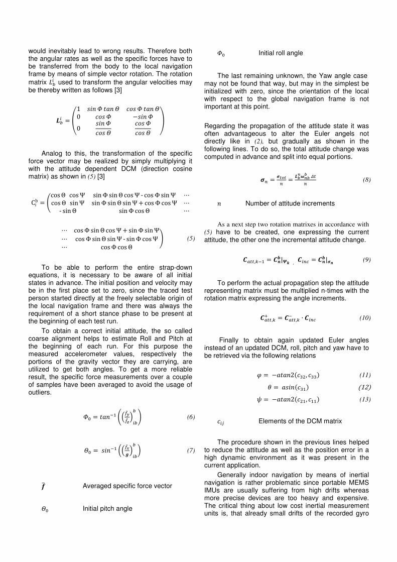
would inevitably lead to wrong results. Therefore both the angular rates as well as the specific forces have to be transferred from the body to the local navigation frame by means of simple vector rotation. The rotation matrix ��� used to transform the angular velocities may be thereby written as follows [3]
�� � �1 ��� � ��� � !� � ��� �0 !� � ���� �0 ��� � !� � !� � !� � # Analog to this, the transformation of the specific
force vector may be realized by simply multiplying it with the attitude dependent DCM (direction cosine matrix) as shown in (5) [3]
Cib � 'cos Θ cos Ψ sin Φ sin Θ cos Ψ - cos Φ sin Ψ ⋯cos Θ sin Ψ sin Φ sin Θ sin Ψ � cos Φ cos Ψ ⋯- sin Θ sin Φ cos Θ ⋯
⋯ cos Φ sin Θ cos Ψ � sin Φ sin Ψ⋯ cos Φ sin Θ sin Ψ - sin Φ cos Ψ⋯ cos Φ cos Θ 1 (5)
To be able to perform the entire strap-down equations, it is necessary to be aware of all initial states in advance. The initial position and velocity may be in the first place set to zero, since the traced test person started directly at the freely selectable origin of the local navigation frame and there was always the requirement of a short stance phase to be present at the beginning of each test run.
To obtain a correct initial attitude, the so called coarse alignment helps to estimate Roll and Pitch at the beginning of each run. For this purpose the measured accelerometer values, respectively the portions of the gravity vector they are carrying, are utilized to get both angles. To get a more reliable result, the specific force measurements over a couple of samples have been averaged to avoid the usage of outliers.
�2 � ���� 3457̅58̅9��� : (6)
�2 � ���� ;45<̅� 9��
� = (7) �> Averaged specific force vector �2 Initial pitch angle
�2 Initial roll angle
The last remaining unknown, the Yaw angle case may not be found that way, but may in the simplest be initialized with zero, since the orientation of the local with respect to the global navigation frame is not important at this point.
Regarding the propagation of the attitude state it was often advantageous to alter the Euler angels not directly like in (2), but gradually as shown in the following lines. To do so, the total attitude change was computed in advance and split into equal portions.
?� � ?@A@� � BC�CBB DE� (8) � Number of attitude increments
As a next step two rotation matrixes in accordance with
(5) have to be created, one expressing the current attitude, the other one the incremental attitude change.
�FEE,� � �HI|�K , ���L � �HI|?H (9) To perform the actual propagation step the attitude
representing matrix must be multiplied n-times with the rotation matrix expressing the angle increments.
�FEE,M � �FEE, ∙ ���L (10) Finally to obtain again updated Euler angles
instead of an updated DCM, roll, pitch and yaw have to be retrieved via the following relations
O � �����2Q RS, RRT (11) U � ����Q R�T Q12T V � �����2Q S�, ��T (13) �W Elements of the DCM matrix
The procedure shown in the previous lines helped to reduce the attitude as well as the position error in a high dynamic environment as it was present in the current application.
Generally indoor navigation by means of inertial navigation is rather problematic since portable MEMS IMUs are usually suffering from high drifts whereas more precise devices are too heavy and expensive. The critical thing about low cost inertial measurement units is, that already small drifts of the recorded gyro

rate and specific force measurements, would inevitably lead to massive position failures just after a short time span. Therefore the simple strap-down calculation conducted by means of the information gathered from an IMU is nowadays still not sufficient for navigational issues.
But if the occurring deviations from the true position may be estimated in regular periods, the resulting failures can be reduced to an acceptable level. A possibility to do so is the application of Zero-Velocity-Updates during phases where the foot of the traced person, hence the IMU is at rest.
Therefore one of the major challenges was to detect those mentioned stance phases of the foot the IMU was mounted to. As a side condition served thereby the presumption that the angular velocity has to be rather small (almost zero) during phases when the according foot was attached to the ground. So a threshold regarding the resultant of these angular velocities has to be found, to decide whether a stride or a stance phase was present. After several trials it turned out that a threshold value of approximately 0.2 YFZ[ always yielded quite reliable results when the pedestrian walked at moderate speed. The following figure shows the distinctive gyro rates occurring during a walk.
Figure 9: Detection of stance/stride phases. Mentionable are the distinctive angular rates during each step.
Since it is now possible to distinguish between stationary stance and moving stride phases, one also knows when a zero-velocity update has to be applied to stabilize the IMU based system. In the first place, during a ZUPT the velocity of the pedestrian was set to zero, independent from the acceleration measurements gathered from the IMU. This ensures no position change during this phase of the run. Another task carried out was the dynamic estimation of occurring gyro biases during stance phases which lasted longer than half a second. Thereby the gyro rate measurements were summed up and averaged trough this static period. Since the magnitude of the angular velocity measurements shall be actually equal to zero, the gained result may be directly seen as approximated gyro bias.
I\ � ∑ �CB,^B_̂`ab (14) c No. of gyro rate measurements
Furthermore roll and pitch angle were corrected during each rest phase by means of the already mentioned coarse alignment.
During an active stride phase the ordinary strap-down equations were executed. An exception was the change in vertical direction, which was only possible if a resultant altitude change larger than 0.34m was present. This constraint was based on the knowledge that the height of a standard stair is approximately 0.17m. So attitude changes just initiated by sensor noise or accelerometer biases were hereby eliminated in a quite convenient way. The performance of this approach was also verified during outdoor as well as indoor runs.
B. Integration Filter
The actual integration process to merge the different sensor data types was done by means of a Helmert Transformation, implemented strongly in accordance with [4]. Generally this kind of transformation is often used in geodesy to transfer distortion-free from one datum to another [5] using the relation
defg ∙ hi�,jkl � i2,jklm � n2,okll � n�,okll � p� (15) defg Helmert rotation and scaling i�,jkl Actual position in the local frame iq,jkl Averaged position in the local frame n�,okll Actual position in the global frame nq,okll Averaged position in the global p� Position residuum
The letters i and n are thereby complex numbers describing the location of a point within the according coordinate frame. Thereby the real and imaginary parts of ijkl can be seen as the x and y coordinates within the local navigation frame. In analogy, the components of the complex number nokll represent the position in North and East direction in global coordinates.
To be able to perform such a Helmert transformation, a certain number (at least two) of coordinate points in both coordinate systems have to be known in advance.

The coordinates Z2,okll and i2,jkl may be thereby seen as centroids of the point clouds given. Hence the following relation is sufficient to determine these magnitudes
iq,jkl � ∑ st,uvwCt`a� , nq,okll � ∑ xt,yvwwCt`a � (16) � No. of separate points used for the
Helmert transformation
The last remaining unknown in equation (15) zefg may be found as follows
defg � hst,uvwsA,uvwmhxt,yvwwxA,yvwwm∗hst,uvwsA,uvwmhst,uvwsA,uvwm∗ (17)
The superior stars in are hereby signing the
complex conjugates.
C. System Process Diagram
Referring to Figure 10 one can see that the integration filter always waits for incoming WGS84 positions and discards them if they are flagged by the In-track Chip as invalid. Valid positions are processed and stored in a kind of position ring buffer which is filled up till a predefined number of location entries is reached. In the event that the necessary number of positions is stored in the buffer, the filter conducts a new Helmert Transformation.
Apart from this, in each epoch the usual strap-down equations are executed. Thereby the algorithm always detects whether a stride or a stance phase is present. Additionally to a ZUPT, gyro bias and attitude are estimated regularly through rest periods. During phases where motion is detected, attitude, velocity and position are propagated under the consideration of the attitude change constraint.
Figure 10: Filter process diagram
VI. TEST RESULTS
First tests conducted at the University of Applied Science in Graz served to validate the implemented strapdown-algorithm with its modifications e.g. the application of ZUPTs. So initially, positioning just by means of inertial navigation has been performed. The results of a pretty successful run are presented in Figure 11 and Figure 12.

Figure 11: Top view of a test run at the University
First the test person walked a few times back and forth, afterwards entered a staircase and went down from the second to the ground floor of the university. The distinctive motion during downwards or upwards steps can be clearly seen in Figure 12. After this nine minutes lasting run, roughly a total distance of approximately 600m was covered, whereas the start and end points were identically. Finally a remarkable small accumulated position error of about 1.4m was present at the end of the run.
It should be also mentioned that the current example represents the ideal case and is chosen to point out the capabilities of sole inertial navigation. In most test cases, the resulting position deviation was about several meters, what was finally the reason for the introduction of recalibration QR reference codes.
Figure 12: Front view of a test run at the University
A problem encountered during the validation of the system was the high dynamic environment the IMU has to cope with. The regular exceedance of the nominal measuring range (+/-8g and +/-480°/s) stated by the manufacturer led to unavoidable failures within the strap-down algorithm, hence to inevitable attitude and position errors. This fact is also illustrated in Figure 13
Figure 13: Recorded gyro rate and specific force values. Noticeable is the unfavorable regular exceedance of the
+/-8g border

A final test in the form of a demonstration was performed at Terminal 1 of the Munich International Airport. To make the demo as realistic as possible, not an IFEN employee but a professional firefighter in complete first aid clothing served as test person. In Figure 14 and Figure 15 one sees the firefighter’s resultant motion in horizontal and vertical direction.
Figure 14: Motion in the vertical plane
Similar to prior performed tests, also this run started outdoors. The position jump at the very beginning of the demonstration is thereby a result of inaccurate GNSS position measurements close to the terminal construction. However, the occurring error was compensated by the first QR tag placed at the buildings entrance.
Figure 15: Motion in height direction
During the movement at a certain level, the height may be estimated quite well. The main height errors arose during phases when the fire-fighter climbed up stairs in his heavy clothing. But also these errors were corrected by means of QR markers placed at the end of each staircase.
VII. CONCLUSIONS
In this paper we introduced an integrated navigation device for supporting fire fighters. Thereby a
MEMS IMU from InterSense (NavChip) was used for navigation in areas where no or just a insufficiently accurate GNSS position was available. With respect to its small dimensions, what was an indispensable requirement, the performance of the NavChip IMU may be finally seen as sufficient for this type of application. However, even if ZUPT aided short term navigation was possible by means of inertial navigation, tracing a fire-fighter over a longer timespan was impossible with the IMU alone.
Outdoors the integration filter was recalibrated by means of GNSS position information. Indoors QR codes containing exact WGS84 position information were placed at important strategic points, e.g. at the beginning or at the end of a stairway, for system recalibration issues.
After the evaluation of all performed investigations, the performance of the overall system may be generally seen as sufficient for the tracking of fire fighters in emergency situations, since the accruing position errors stay in the lower meter range. So a fast location estimate of a first aider in distress e.g. within a burning building is always feasible. What can be said is that the introduction of such a tracking system would definitely support and facilitate the daily business of search and rescue forces.
VIII. ACKNOWLEDGEMENTS
This work has been partly performed within the DLR project INDOOR funded by the German Aerospace Center (DLR) on behalf of Federal Ministry of Economics and Technology (BMWI), Grant Contract No. FKZ 50 NA 0504.
IX. REFERENCES
[1] InterSense Incorporated, ‘NavChip’, URL:http://www.
intersense.com/pages/16/16
[2] E. Foxlin, ‘Pedestrian tracking with shoe-mounted inertial sensors’, IEEE Computer Graphics and Applications, vol.25, no.6, November/December 2005
[3] J. Wendel, ‘Integrierte Navigationssysteme’, Oldenburg
Wissenschaftsverlag, 2011, Munich
[4] W. Volk, ‘Mathematischer Exkurs II – Die Helmert
Transformation’, URL: http://www.w-volk.de/museum/ mathex02.htm
[5] Wikimedia Foundation Inc., ‘Helmert Transformation’, URL: http://en.wikipedia.org/wiki/Helmert_transformation
[6] Oberpriller A., “Immer einen Schritt voraus”, MUC – Die Flughafen Zeitung, Februar 2013, pp.8