IFDTM Sensor Installation Guide - IFD Corporation
20
© IFD Corporation, 2001-2014 IFD TM Sensor Installation Guide How to successfully install the IFD sensor
Transcript of IFDTM Sensor Installation Guide - IFD Corporation

© IFD Corporation, 2001-2014
IFDTM Sensor Installation Guide How to successfully install the IFD sensor

IFD™ Sensor Installation Guide
IFD-OEM-IG-2017-02
i
Foreword First of all, welcome to the IFD team! While this may sound a little on the fluffy side, we really do mean it.
We’re committed to reducing the risks line workers face and, with your decision to install IFD sensors it’s
clear you’re committed to the same goal. That being said, here’s what you can expect from your new
support team.
We will listen If you have any questions, ideas or concerns please let us know and someone will be happy to
discuss them with you.
You will get answers No matter what comes up over time you can rest assured our team won’t stop until your curiosity is
fully satisfied. Even if it has nothing to do with our products we will do our best to help out and if
we can’t find an answer, we can often connect you with someone who can.
We will make it right We work hard to meet your requirements, but we also recognize that learning and continuous
improvement are important parts of the customer support process. So, if we haven’t fully met your
expectations we welcome your feedback and the opportunity to learn and correct it for you.
We will strive to be your best supplier We mean this, and we mean it regardless of your size or location. We will always remain
committed to your success.
We will be there to support you every step of the way Just call and we’re on it, from the initial on-site training provided by our engineering team through
to when the very oldest IFD sensor you’ve installed comes out of service.
You will have direct access to anyone on our team No joke. Everyone on our team would be happy to take your call and take pride in the opportunity
to work with you.
Finally, we’d just like to say thank you for your business, and thank you for taking action to help create a
faster, safer and better utility industry.
How to contact us
1-604-734-0105
www.ifdcorporation.com

IFD™ Sensor Installation Guide
IFD-OEM-IG-2017-02
ii
Table of Contents Foreword ........................................................................................................................................... i
About the IFD sensor ......................................................................................................................... 3
Why the IFD sensor was invented ............................................................................................................ 3
The 2 functions of the IFD sensor ............................................................................................................. 4
Transformer design requirements ...................................................................................................... 5
Minimum oil clearance ............................................................................................................................. 5
Lid clearance ............................................................................................................................................. 5
Component clearance ............................................................................................................................... 5
Shipping Lock clearance ............................................................................................................................ 6
Wall thickness ........................................................................................................................................... 6
Tips and tricks ........................................................................................................................................... 6
Mounting hole specifications ............................................................................................................. 7
Cut-out ...................................................................................................................................................... 7
Key ............................................................................................................................................................ 7
Flat boss .................................................................................................................................................... 7
Installation specifications .................................................................................................................. 7
Torque specification ................................................................................................................................. 7
Purchasing configurations and tooling options ................................................................................... 8
Unassembled configuration ...................................................................................................................... 8
Assembled configuration .......................................................................................................................... 8
Tooling selection guide ............................................................................................................................. 9
PRV options ...................................................................................................................................... 9
Installing the IFD sensor .................................................................................................................. 10
Best practices for installation ........................................................................................................... 10
Have IFD staff run a training session ...................................................................................................... 10
Use visual work instructions ................................................................................................................... 10
Use appropriate sized torque wrench .................................................................................................... 10
Ensure the IFD sensor is always locked out ............................................................................................ 11
Install the IFD decal ................................................................................................................................ 11
Perform end of line inspections ............................................................................................................. 11
Maintain IFD sensor training .................................................................................................................. 11
Common questions ......................................................................................................................... 12
Can I put the IFD sensor through a paint curing oven? .......................................................................... 12
What if the IFD sensor activates during production? ............................................................................. 12
I am unable to reset the IFD sensor, what is next? ................................................................................ 12
What should I do if an IFD equipped transformer needs investigation? ............................................... 12
Appendix A: IFD sensor drawing ...................................................................................................... 13
Appendix B: Visual work instructions ............................................................................................... 15

IFD™ Sensor Installation Guide
IFD-OEM-IG-2017-02
3
About the IFD sensor Since its introduction in 2001 line crews have come to trust the IFD sensor to tell them when a transformer
has a dangerous internal fault. Today the IFD sensor is a benchmark in transformer safety that provides a
simple, easy-to-use message:
“See the signal, replace the transformer!”
The IFD sensor detects and indicates low impedance internal
arcing faults in pole mounted and pad mounted distribution
transformers by releasing a highly visible orange indicator.
When crews see this orange signal they know immediately the
transformer is faulted and needs to be replaced.
In addition to improving worker safety, the maintenance free
IFD mechanical sensor provides set-it-and-forget-it operation
and a typical 12:1 return on investment over the life of the
transformer.
Why the IFD sensor was invented
The IFD sensor evolved out of an industry objective to build a safer distribution transformer for line workers
to interact with. This included many studies focused on learning how internal arcing faults developed and
what the resulting internal pressures looked like inside the transformer. It was this research that
uncovered the unique link between a low impedance internal arcing fault and a characteristic rapid
pressure rise that followed in the airspace. It was observed that while this pressure rise had variable peak
pressures it exhibited a consistent rate of rise in excess of 0.5 psi / 7 ms. This rapid rate of pressure rise is
the fingerprint of a low impedance internal arcing fault that can cause tank rupture, and pose the highest
risk to line workers.

IFD™ Sensor Installation Guide
IFD-OEM-IG-2017-02
4
The 2 functions of the IFD sensor
The IFD sensor is a two function device. Its primary function is to identify transformers with dangerous, low
impedance internal faults. Its secondary function is to provide a means for standard pressure relief.
Primary function of the IFD sensor – Internal fault detection The primary function of the IFD sensor is to detect and indicate rapid internal pressure rises associated with
low impedance internal faults. These types of rapid pressure rises can develop 50 – 1500 times faster than
the pressure build ups the pressure relief valve (PRV) is designed to vent. The potential for tank ruptures of
these high energy internal faults is why the industry has developed manufacturing standards for tank
strength, and continues to seek additional safety improvements to help protect line workers.
The IFD sensor is calibrated to activate when there is a pressure rise of 0.5 psi / 7 ms, or larger in the
airspace of the transformer. This low activation threshold allows crews to avoid re-energizing transformers
with potentially dangerous faults, even if the initial fault that caused power outage was well below the
point of visible damage to the transformer. The transformer will remain sealed once the IFD sensor has
activated.
Secondary function of the IFD sensor – Pressure relief The IFD sensor also incorporates a standard PRV in order to provide both functions through the same hole
in the transformer tank wall.
The PRV allows for automatic or manual venting when
internal pressures rise slowly. These slow pressure build
ups have various causes including high ambient
temperatures, overloading and low energy internal
faults. In these cases, the PRV protects the transformer
by venting gases before they pose a risk to the
transformer. The PRV will continue to function if the IFD
sensor has activated.
The PRV specifications can be selected to meet either the
IEEE or CSA standards requirements.
Pressure relief valve
Rapid pressure rise (0.5 psi / 7ms or larger)
Highly visible orange indicator activates
IFD™ Sensor Installation Guide
IFD-OEM-IG-2017-02
5
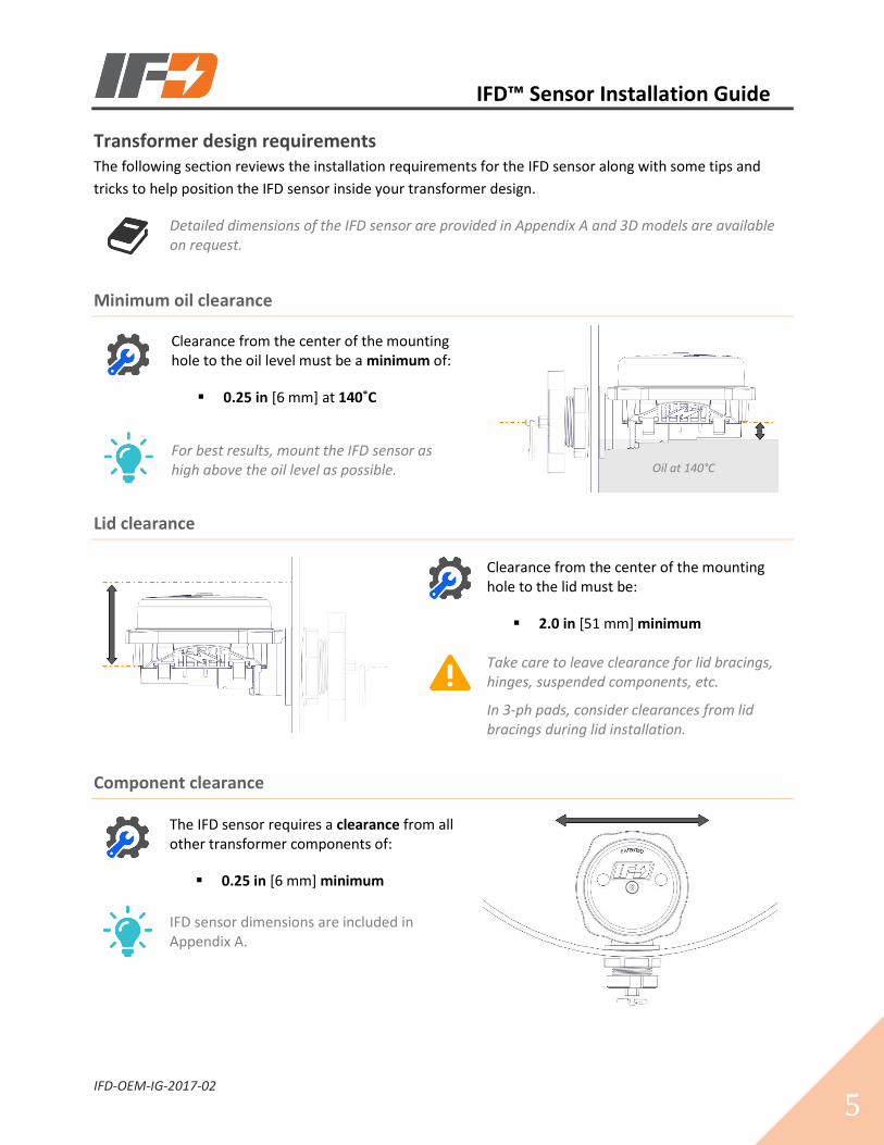
Transformer design requirements The following section reviews the installation requirements for the IFD sensor along with some tips and
tricks to help position the IFD sensor inside your transformer design.
Detailed dimensions of the IFD sensor are provided in Appendix A and 3D models are available on request.
Minimum oil clearance
Clearance from the center of the mounting hole to the oil level must be a minimum of:
▪ 0.25 in [6 mm] at 140˚C
For best results, mount the IFD sensor as high above the oil level as possible.
Lid clearance
Clearance from the center of the mounting hole to the lid must be:
▪ 2.0 in [51 mm] minimum
Take care to leave clearance for lid bracings, hinges, suspended components, etc.
In 3-ph pads, consider clearances from lid bracings during lid installation.
Component clearance
The IFD sensor requires a clearance from all other transformer components of:
▪ 0.25 in [6 mm] minimum
IFD sensor dimensions are included in Appendix A.
Oil at 140°C
IFD™ Sensor Installation Guide
IFD-OEM-IG-2017-02
6
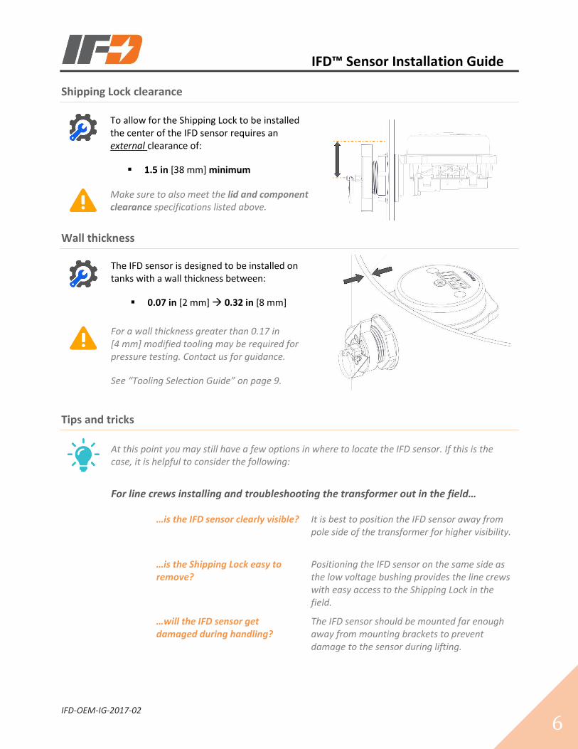
Shipping Lock clearance
To allow for the Shipping Lock to be installed the center of the IFD sensor requires an external clearance of:
▪ 1.5 in [38 mm] minimum
Make sure to also meet the lid and component clearance specifications listed above.
Wall thickness
The IFD sensor is designed to be installed on tanks with a wall thickness between:
▪ 0.07 in [2 mm] 0.32 in [8 mm]
For a wall thickness greater than 0.17 in [4 mm] modified tooling may be required for pressure testing. Contact us for guidance.
See “Tooling Selection Guide” on page 9.
Tips and tricks
At this point you may still have a few options in where to locate the IFD sensor. If this is the case, it is helpful to consider the following:
For line crews installing and troubleshooting the transformer out in the field…
…is the IFD sensor clearly visible? It is best to position the IFD sensor away from pole side of the transformer for higher visibility.
…is the Shipping Lock easy to remove?
Positioning the IFD sensor on the same side as the low voltage bushing provides the line crews with easy access to the Shipping Lock in the field.
…will the IFD sensor get damaged during handling?
The IFD sensor should be mounted far enough away from mounting brackets to prevent damage to the sensor during lifting.
IFD™ Sensor Installation Guide
IFD-OEM-IG-2017-02
7
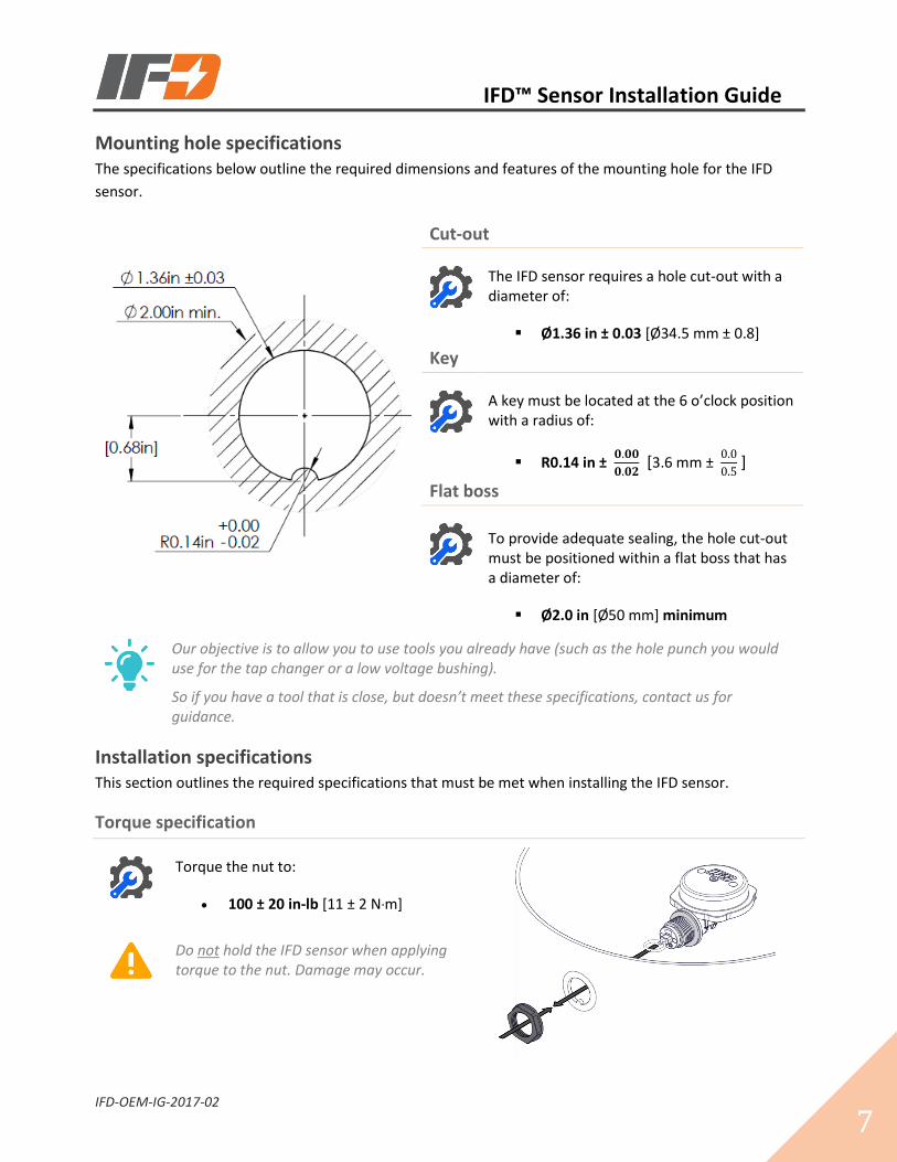
Mounting hole specifications The specifications below outline the required dimensions and features of the mounting hole for the IFD
sensor.
Cut-out
The IFD sensor requires a hole cut-out with a diameter of:
▪ Ø1.36 in ± 0.03 [Ø34.5 mm ± 0.8]
Key
A key must be located at the 6 o’clock position with a radius of:
▪ R0.14 in ± 𝟎.𝟎𝟎
𝟎.𝟎𝟐 [3.6 mm ±
0.0
0.5 ]
Flat boss
To provide adequate sealing, the hole cut-out must be positioned within a flat boss that has a diameter of:
▪ Ø2.0 in [Ø50 mm] minimum
Our objective is to allow you to use tools you already have (such as the hole punch you would use for the tap changer or a low voltage bushing).
So if you have a tool that is close, but doesn’t meet these specifications, contact us for guidance.
Installation specifications This section outlines the required specifications that must be met when installing the IFD sensor.
Torque specification
Torque the nut to:
• 100 ± 20 in-lb [11 ± 2 N·m]
Do not hold the IFD sensor when applying torque to the nut. Damage may occur.
IFD™ Sensor Installation Guide
IFD-OEM-IG-2017-02
8
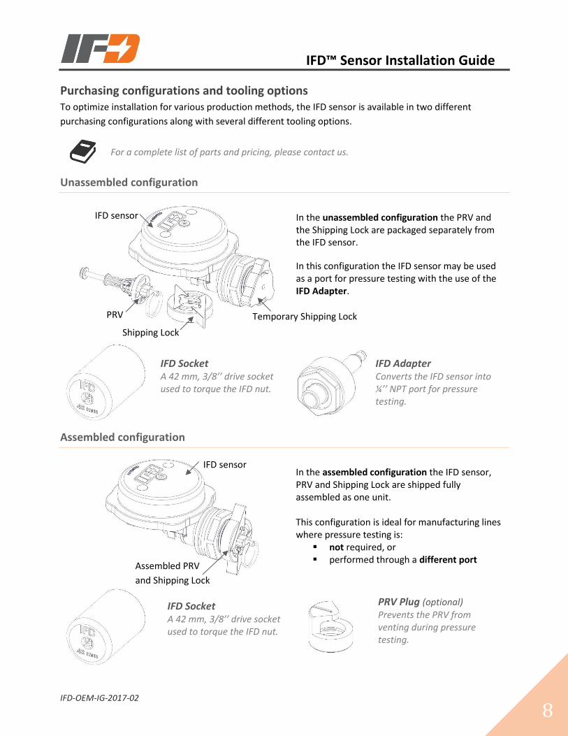
Purchasing configurations and tooling options To optimize installation for various production methods, the IFD sensor is available in two different
purchasing configurations along with several different tooling options.
For a complete list of parts and pricing, please contact us.
Unassembled configuration
In the unassembled configuration the PRV and the Shipping Lock are packaged separately from the IFD sensor.
In this configuration the IFD sensor may be used as a port for pressure testing with the use of the IFD Adapter.
IFD Socket A 42 mm, 3/8’’ drive socket used to torque the IFD nut.
IFD Adapter
Converts the IFD sensor into ¼’’ NPT port for pressure testing.
Assembled configuration
In the assembled configuration the IFD sensor, PRV and Shipping Lock are shipped fully assembled as one unit. This configuration is ideal for manufacturing lines where pressure testing is:
▪ not required, or ▪ performed through a different port
IFD Socket A 42 mm, 3/8’’ drive socket used to torque the IFD nut.
PRV Plug (optional) Prevents the PRV from venting during pressure testing.
IFD sensor
PRV
Shipping Lock
Temporary Shipping Lock
IFD sensor
Assembled PRV
and Shipping Lock
IFD™ Sensor Installation Guide
IFD-OEM-IG-2017-02
9
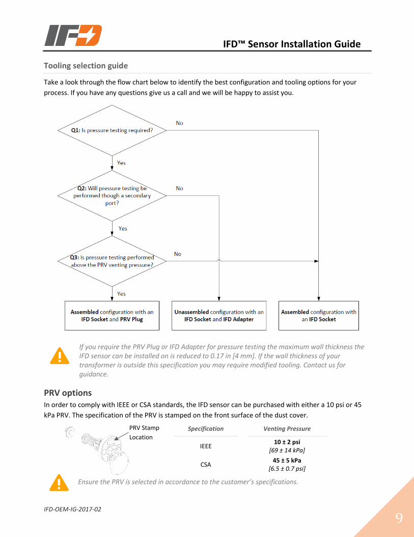
Tooling selection guide
Take a look through the flow chart below to identify the best configuration and tooling options for your
process. If you have any questions give us a call and we will be happy to assist you.
If you require the PRV Plug or IFD Adapter for pressure testing the maximum wall thickness the IFD sensor can be installed on is reduced to 0.17 in [4 mm]. If the wall thickness of your transformer is outside this specification you may require modified tooling. Contact us for guidance.
PRV options In order to comply with IEEE or CSA standards, the IFD sensor can be purchased with either a 10 psi or 45
kPa PRV. The specification of the PRV is stamped on the front surface of the dust cover.
Specification
Venting Pressure
IEEE 10 ± 2 psi
[69 ± 14 kPa]
CSA 45 ± 5 kPa
[6.5 ± 0.7 psi]
Ensure the PRV is selected in accordance to the customer’s specifications.
PRV Stamp
Location
IFD™ Sensor Installation Guide
IFD-OEM-IG-2017-02
10
Installing the IFD sensor Complete step by step guides to installing the various configurations along with tooling options are
included in Appendix B.
The IFD sensor is a device designed for line worker safety. If a unit is damaged during installation or if damage is suspected, please contact us immediately. We will ask you to return the sensor to us for inspection and issue you a credit for replacement.
Best practices for installation We’ve learned a lot from our customers over the years! The intent of this section is to pass along the
learning from our combined experience and to highlight some of the best practices used to ensure seamless
integration of the IFD sensor into your production line.
Have IFD staff run a training session
We offer onsite training to all our customers. From experience, face-to-face training will create value in a
number of ways:
▪ Get real-time feedback on how to effectively integrate the IFD sensor into your production line
▪ Take advantage of our experience to ensure quality is high from the get-go
▪ Put a face behind the product, so when a question arises you know who to call
Our goal behind these training sessions is for you to be as prepared as possible to install the IFD sensor successfully. So don’t hesitate to contact us -- arrange a training session today!
Use visual work instructions
We have learned visual work instructions are powerful tools for production environments. We encourage
you to print out the instruction set that applies to your process and display it for easy reference on the
production line.
Shop floor instructions for each of the different configurations and tooling options are included in Appendix B.
Use appropriate sized torque wrench
The IFD nut requires a torque value of 100 ± 20 in-lb [11 ± 2 Nm] for proper gasket sealing. Using a torque
wrench where the target value is near the mid-range of the wrench capacity will allow operators to
consistently meet the IFD nut torque requirement.
IFD™ Sensor Installation Guide
IFD-OEM-IG-2017-02
11
Ensure the IFD sensor is always locked out
To prevent premature activations that may occur while handling the transformer the IFD sensor must
always be locked out with one of the following:
▪ Shipping Lock
▪ PRV Plug
▪ IFD Adapter
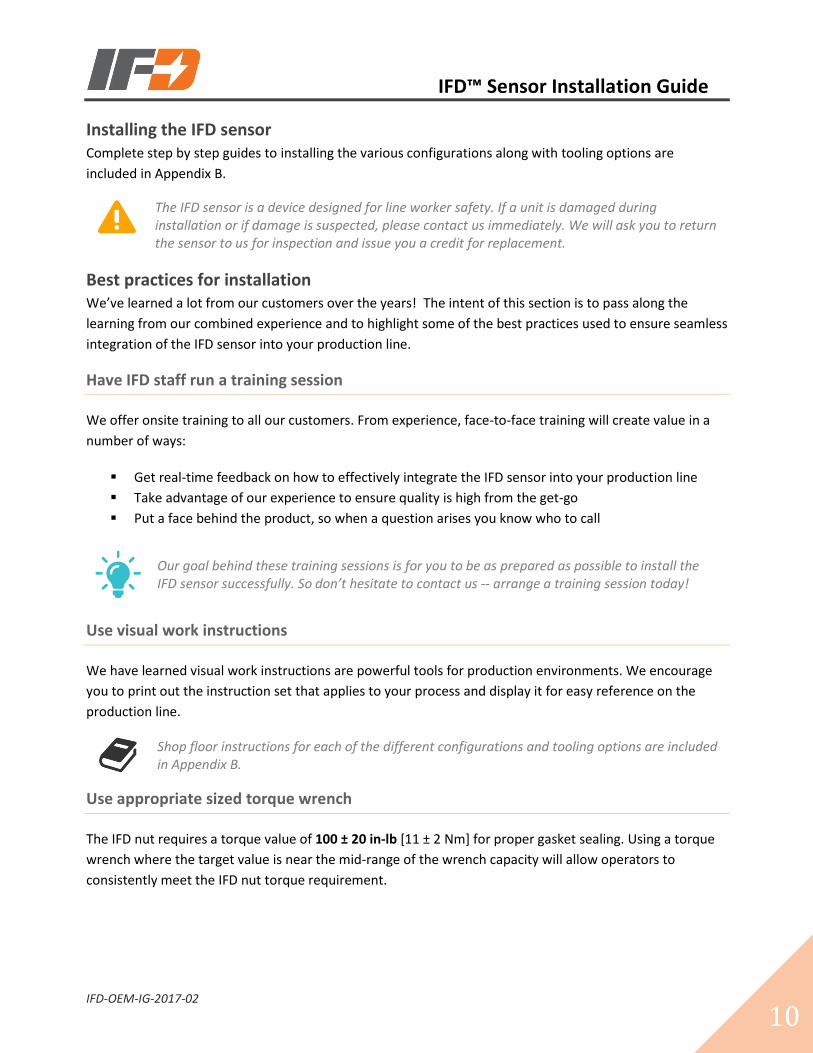
Install the IFD decal
The IFD decal is a training document that reminds line crews how to work with an IFD equipped
transformer. The IFD decal should be installed on the outside of the transformer as close to the IFD sensor
as possible.
The IFD Decal can be placed below, or on either side of the IFD sensor.
Perform end of line inspections
We recommend a simple, three-step, end of line quality check for the IFD sensor. The visual work
instructions for these checks are outlined in Appendix B and consist of the following:
Three-step, end of line quality check
1. Verify IFD sensor installation
Remove Shipping Lock to check that the indicator does not activate
2. Verify PRV installation Tug Pull Ring to check Spring Retainer installation or Push and rotate PRV Dust Cover until Spring Retainer clicks into place
3. Verify Shipping Lock and Decal installation
Ensure the Shipping Lock is fully engaged with tabs in the vertical position and Check that the IFD Decal is positioned near the IFD sensor
Maintain IFD sensor training
While initial training is very important, that training won’t last forever as there are always new people
coming onto the line. Running periodic training sessions ensures any new operators are fully up to speed
and serves as a great refresher for your experienced people.
All our training material can be found online at www.ifdcorporation.com or, contact us and we can send our training material directly to you.
IFD Decal

IFD™ Sensor Installation Guide
IFD-OEM-IG-2017-02
12
Common questions This section answers some questions you may have during installation of the IFD sensor. If you have a
question that is not covered here give us a call and we will be happy to help you out.
Can I put the IFD sensor through a paint curing oven?
It is common for the IFD sensor to be processed through a paint curing oven after it is installed in a
transformer. As every process is a little different please contact our engineering team for further details.
What if the IFD sensor activates during production?
Without locking out the IFD sensor it is possible for premature activation to occur during handling. If this
happens, the IFD Reset Tool will allow you to reset the sensor without opening the transformer. Before
resetting the IFD sensor it is important double check that no damage is suspected to either the transformer
or IFD sensor.
It is only acceptable to reset the IFD sensor if…
1. You are confident that the transformer has never been energized / does not
contain an internal arcing fault
2. No damage to the IFD sensor is suspected (ie. hitting it or dropping it)
NEVER TRY TO RESET THE IFD SENSOR BY PUSHING ON THE ORANGE INDICATOR. Doing so may result in permanent damage to the sensor.
Further information about the IFD Reset Tool including a user manual and video is available on our website at www.ifdcorporation.com.
I am unable to reset the IFD sensor, what is next?
This likely indicates the IFD sensor is damaged and needs to be replaced. Please contact us and we will issue
a credit for a replacement upon return of the damaged unit.
What should I do if an IFD equipped transformer needs investigation?
Please contact us and one of our engineers will guide you through our investigation process. Some of the
information we will need to get started is:
▪ Description of what happened / the situation
▪ Current location / status of the IFD sensor
▪ Transformer information: type, size, serial number, manufacturing date
▪ We would also appreciate any available pictures
Please ensure you retain the IFD sensor as we will need it returned for further analysis.

IFD™ Sensor Installation Guide
13
Appendix A: IFD sensor drawing

2.15in55mm
0.28in7mm
3.99in101mm
1.75in44mm
1.77in45mm
1.27in32mm
3.70in94mm
IFD-DWG-2016-00
IFD Orca0See IFD price list
REVPART NO.
ASIZE
TITLE:
THE INFORMATION CONTAINED IN THISDRAWING IS THE SOLE PROPERTY OFIFD CORP. ANY REPRODUCTION IN PARTOR AS A WHOLE WITHOUT THE WRITTEN PERMISSION OF IFD CORP. IS PROHIBITED.
5 4 3 2 1
PROPRIETARY AND CONFIDENTIAL
IFD Corporation
Page 1 of 1

IFD™ Sensor Installation Guide
15
Appendix B: Visual work instructions
Installing the IFD sensor………………………………………………………………..…………………………… 16
Installing the IFD sensor with PRV Plug ……………………………………………………………..………. 17
Installing the IFD sensor with IFD Adapter……............................................................... 18
End of line quality checks…………………………………………………………..…………………………….. 19

Installing the IFD sensor
IFD-VWI-STD-2017-01
PREPARE SENSOR
❶Turn shipping lock 90˚ counter- clockwise.
❷Remove and retain shipping lock.
❸Remove nut. Make sure gasket remains on IFD body.
Gasket
❹Align keyway and insert the IFD sensor into the mounting hole.
❺Install nut. Tighten by hand until snug.
INSTALL SHIPPING LOCK
❼ Slide shipping lock over PRV pull ring.
❽Push and rotate shipping lock 90˚ clockwise.
❾Install the IFD decal.
❻ Torque the nut to:
▪ 100 ± 20 in-lb [11 ± 2 Nm]
Important: Do not hold the IFD sensor when applying torque to the nut. Damage may occur.
INSTALL DECAL
INSTALL SENSOR
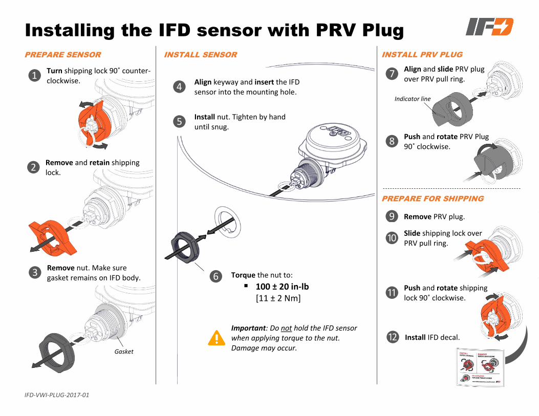
Installing the IFD sensor with PRV Plug
IFD-VWI-PLUG-2017-01
PREPARE SENSOR
❶Turn shipping lock 90˚ counter- clockwise.
❷Remove and retain shipping lock.
INSTALL PRV PLUG
❼ Align and slide PRV plug over PRV pull ring.
⓫Push and rotate shipping lock 90˚ clockwise.
❻ Torque the nut to:
▪ 100 ± 20 in-lb [11 ± 2 Nm]
Important: Do not hold the IFD sensor when applying torque to the nut. Damage may occur.
PREPARE FOR SHIPPING
❽Push and rotate PRV Plug 90˚ clockwise.
❾ Remove PRV plug.
❿ Slide shipping lock over
PRV pull ring.
INSTALL SENSOR
Indicator line
❸Remove nut. Make sure gasket remains on IFD body.
Gasket
❹Align keyway and insert the IFD sensor into the mounting hole.
❺Install nut. Tighten by hand until snug.
⓬Install IFD decal.

Installing the IFD sensor with IFD Adapter
IFD-VWI-ADPT-2017-01
PREPARE SENSOR INSTALL PRV
❶Twist temporary lock 90˚ counter-clockwise.
❷Remove and recycle (discard) temporary lock.
❸Remove nut. Make sure gasket remains on IFD body.
Gasket
❽Remove IFD adapter.
❾
Insert PRV into the IFD indicator.
PREPARE FOR SHIPPING
⓫ Slide shipping lock over PRV pull ring.
⓬Push and rotate shipping lock 90˚ clockwise.
⓭Install IFD decal.
❿Push and rotate until PRV snaps into place.
❻ Torque the nut to:
▪ 100 ± 20 in-lb [11 ± 2 Nm]
Important: Do not hold the IFD sensor when applying torque to the nut. Damage may occur.
❼Insert IFD adapter and torque to:
▪ 80 ± 10 in-lb [9 ± 1 Nm]
INSTALL SENSOR
❹Align keyway and insert the IFD sensor into the mounting hole.
❺Install nut. Tighten by hand until snug.
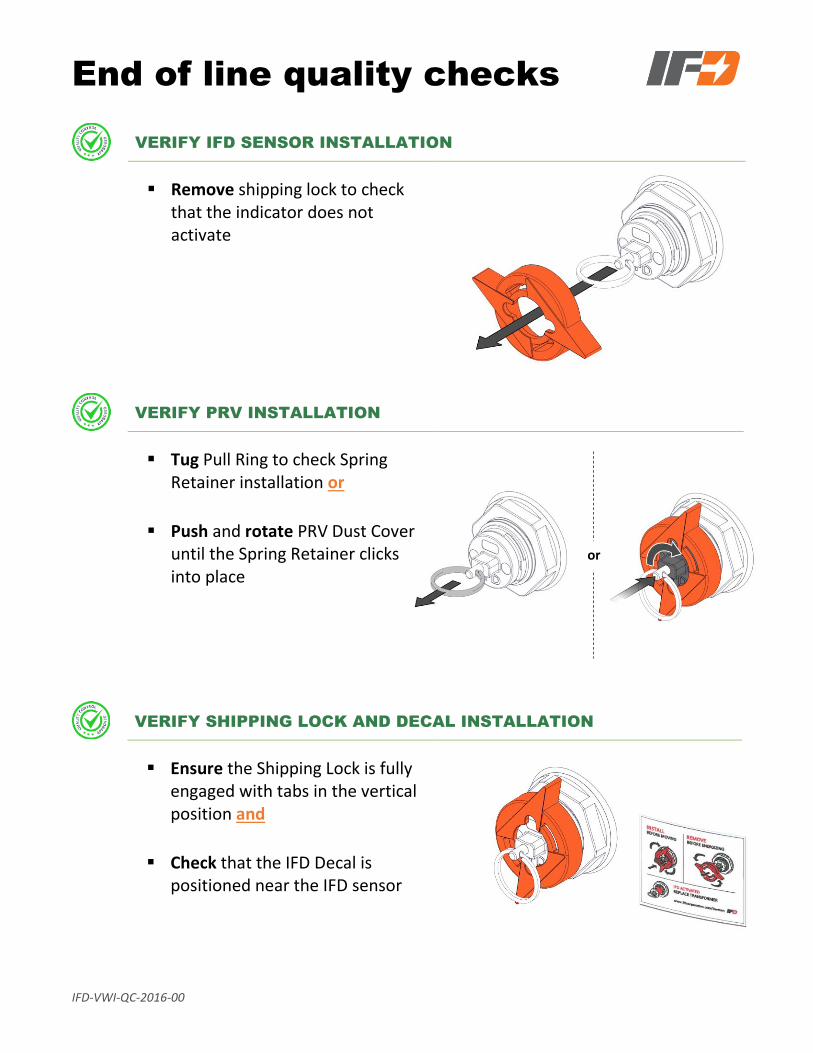
End of line quality checks
IFD-VWI-QC-2016-00
or
VERIFY IFD SENSOR INSTALLATION
Remove shipping lock to check that the indicator does not activate
VERIFY PRV INSTALLATION
Tug Pull Ring to check Spring Retainer installation or
Push and rotate PRV Dust Cover until the Spring Retainer clicks into place
VERIFY SHIPPING LOCK AND DECAL INSTALLATION
Ensure the Shipping Lock is fully engaged with tabs in the vertical position and
Check that the IFD Decal is positioned near the IFD sensor


![]ifd - Annual report](https://static.fdocuments.in/doc/165x107/6192eb041c9f644d2e278ca3/ifd-annual-report.jpg)