June 21 2012 neah bay constitution tunnel space shuttle-other-launch-business plans template sales

University of Victoria Department of
Mechanical Engineering IESVic
Nov. 6 2007
Mech 549
Nov. 6, 2007
University of Victoria Department of
Mechanical Engineering IESVic
Nov. 6 2007
Micro Fuel Cells Potential
• Longer Duration for equivalent weight &
volume Energy Density
• Instant Charge
• Flat Discharge
• Low Self-Discharge
• Little Short-circuit protection required
• Cost Competitive (US$ 2-5 / Watt)

University of Victoria Department of
Mechanical Engineering IESVic
Nov. 6 2007
Samsung’s View
2002 2004 2006 2008 2010
100 – 300W 10 – 50W 2 – 5W
Portable Power
Notebook PC
4G Mobile Device
Ubiquitous Computing
150wh/l, 500 hours 300wh/l, 2000 hours 500wh/l, 5000 hours
•DMFC Focus•Moving from Conventional to MEMS technology
Conventional Monopolar MEMS
Source: Samsung Advanced Institute of Technology
University of Victoria Department of
Mechanical Engineering IESVic
Nov. 6 2007
Development Activities
• ~ 100 companies active in the area(primarily stack focussed)
• Companies cluster according to systemarchitecture and fuel choice
• Fuel Axis:Methanol Hydrogen
• Architecture Axis:Miniaturized Novel
Conventional Microfabricated

University of Victoria Department of
Mechanical Engineering IESVic
Nov. 6 2007
Commercial Technology Map(source: Ged McLean-Angstrom Power)
Novel Architecture
Conventional Architecture
MeOH H2
Motorola,Fraunhofer,Ball
Palcan, Jadoo, NovarsLyntech, Masterflex
Microcell, IFCT,Universities
Po
lyfu
el
MT
I M
icro Medis
Neah
Smart FC
Manhattan
JapaneseElectronicsManufacturers
University of Victoria Department of
Mechanical Engineering IESVic
Nov. 6 2007
The Motivation for Methanol

University of Victoria Department of
Mechanical Engineering IESVic
Nov. 6 2007
DMFC -- PEMFC
• Anode Reaction
CH3OH + H2O 6H+ + 6e- + CO2
• Cathode Reaction
1.5O2 + 6H+ + 6e- 3 H2O
• 6 electrons/molecule of MeOH
V21.16
102.6983
===FnF
gE r
University of Victoria Department of
Mechanical Engineering IESVic
Nov. 6 2007

University of Victoria Department of
Mechanical Engineering IESVic
Nov. 6 2007
Anode ReactionCH3OH + H2O 6H+ + 6e- + CO2
Methanol
formeldehyde
Formic acid
Stages Oxidation of Methanol
University of Victoria Department of
Mechanical Engineering IESVic
Nov. 6 2007
Catalysis
• None of these reactions occur as readily asHydrogen oxidation
– Considerable activation overpotential at the Anodeand Cathode (Oxygen reduction)
• Anode uses bimetal catalyst
– Platinum, Ruthenium (usually 50/50 mix)
• Cathode uses Pt, as with H2 Cell

University of Victoria Department of
Mechanical Engineering IESVic
Nov. 6 2007
Catalysis, contd.
• Catalyst loadings tend to be much greaterthan with H2 cells, (up to 10 times thecatalyst)
– To reduce anode overpotential
– Higher costs acceptable (consider batteries)
– Helps with cross-over
University of Victoria Department of
Mechanical Engineering IESVic
Nov. 6 2007
DMFC — PEMFC
• Anode ReactionCH3OH + H2O 6H+ + 6e- + CO2
• Cathode Reaction1.5O2 + 6H+ + 6e- 3 H2O
• Water is consumed at the Anode, and producedmore quickly at the Cathode
• Pure MeOH cannot be used as a fuel– DMFC Water Management issues

University of Victoria Department of
Mechanical Engineering IESVic
Nov. 6 2007
University of Victoria Department of
Mechanical Engineering IESVic
Nov. 6 2007
Fuel Cross-Over
The OCV of a DMFC is considerably lowerthan a Hydrogen Cell, due to Fuel Cross-Over

University of Victoria Department of
Mechanical Engineering IESVic
Nov. 6 2007
Cross-Over Continued
• Methanol mixes very readily with water
• Water is necessary for ionic conductivity (Nafionelectrolyte)
• This methanol will react at the Cathode (Pt catalyst) mixed potential, higher losses
• Fuel Utilization,– f = i/(i+ic)
– ic, cross-over current, current that would have beenproduced without cross-over
University of Victoria Department of
Mechanical Engineering IESVic
Nov. 6 2007
Cross-Over Contd.
f can be as high as 0.85 with proper management
• Make the anode catalyst as active as possible (if allthe fuel reacts it cannot cross-over)
• Control the MeOH supply (low current low supply)Optimal concentration at Anode
• Use thicker electrolytes (150-200μm)

University of Victoria Department of
Mechanical Engineering IESVic
Nov. 6 2007
Commercial Technology Map(source: Ged McLean-Angstrom Power)
Novel Architecture
Conventional Architecture
MeOH H2
Motorola,Fraunhofer,Ball
Palcan, Jadoo, NovarsLyntech, Masterflex
Microcell, IFCT,Universities
Po
lyfu
el
MT
I M
icro Medis
Neah
Smart FC
Manhattan
JapaneseElectronicsManufacturers
University of Victoria Department of
Mechanical Engineering IESVic
Nov. 6 2007
Air-Breathing Fuel Cells
• No oxidant distributionchannels.
• No externalhumidification system.
• No cooling system.
• No hydrogenconditioning.
• No bipolar plates.
Cathode
Anode

University of Victoria Department of
Mechanical Engineering IESVic
Nov. 6 2007
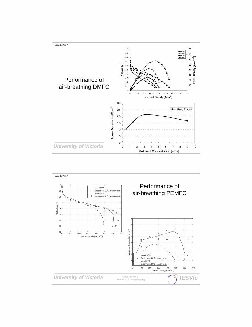
Source: C.Y. Chen, P. Yang, ‘Performance of an air-breathing DMFC’, Journal of Power Sources, 123, 2003
3% wt MeOH
Air-breathing DMFC
University of Victoria Department of
Mechanical Engineering IESVic
Nov. 6 2007
Power and Energy Density

University of Victoria Department of
Mechanical Engineering IESVic
Nov. 6 2007
Other DMFC Systems
MTI Micro
Smart Fuel Cell
University of Victoria Department of
Mechanical Engineering IESVic
Nov. 6 2007
Air-Breathing Hydrogen PEMFCs
C. Hebling, Fraunhofer ISE
University of Victoria Department of
Mechanical Engineering IESVic
Nov. 6 2007
Performance ofair-breathing DMFC
University of Victoria Department of
Mechanical Engineering IESVic
Nov. 6 2007
Performance ofair-breathing PEMFC
0 100 200 300 400 500 600 7000.2
0.3
0.4
0.5
0.6
0.7
0.8
0.9
1
Current Density [mA cm−2]
Cel
l Vol
tage
[v]
Model 20oC
Experiment, 20oC, Fabian et al.
Model 30oC
Experiment, 30oC, Fabian et al.
0 100 200 300 400 500 600 7000
1
2
3
4
5
6
7
8
Current Density [mA cm−2]
Mem
bran
e C
ondu
ctiv
ity [S
m−
1 ]
Model 20oC
Experiment, 20oC, Fabian et al.
Model 30oC
Experiment, 30oC, Fabian et al.
University of Victoria Department of
Mechanical Engineering IESVic
Nov. 6 2007
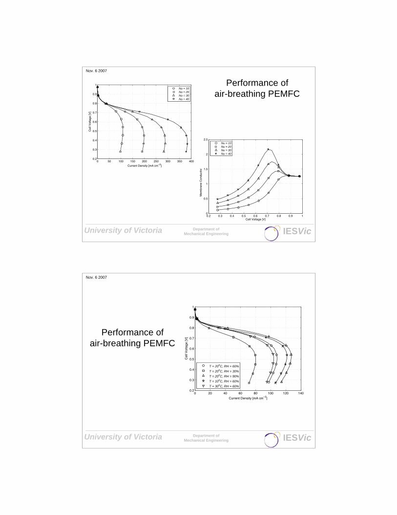
Performance ofair-breathing PEMFC
0.2 0.3 0.4 0.5 0.6 0.7 0.8 0.9 10
0.5
1
1.5
2
2.5
Cell Voltage [V]
Mem
bran
e C
ondu
ctiv
ity [S
m−
1 ]
Nu = 10Nu = 20Nu = 30Nu = 40
0 50 100 150 200 250 300 350 4000.2
0.3
0.4
0.5
0.6
0.7
0.8
0.9
1
Current Density [mA cm−2]
Cel
l Vol
tage
[V]
Nu = 10Nu = 20Nu = 30Nu = 40
University of Victoria Department of
Mechanical Engineering IESVic
Nov. 6 2007
Performance ofair-breathing PEMFC
0 20 40 60 80 100 120 1400.2
0.3
0.4
0.5
0.6
0.7
0.8
0.9
1
Current Density [mA cm−2]
Cel
l Vol
tage
[V]
T = 20oC, RH = 60%
T = 20oC, RH = 30%
T = 20oC, RH = 90%
T = 10oC, RH = 60%
T = 30oC, RH = 60%

University of Victoria Department of
Mechanical Engineering IESVic
Nov. 6 2007
Path forwards?
Novel Architecture
Conventional Architecture
MeOH H2
Motorola,Fraunhofer,Ball
Palcan, Jadoo, NovarsLyntech, Masterflex
Microcell, IFCT,Universities
Po
lyfu
el
MT
I M
icro Medis
Neah
Smart FC
Manhattan
JapaneseElectronicsManufacturers
University of Victoria Department of
Mechanical Engineering IESVic
Nov. 6 2007
Fuel Cell Topology
• Conventional Fuel Cell consists of 8 parallellayers:
1. Fuel Flowfield
2. Gas Diffusion
3. Catalyst
4. Electrolyte
5. Catalyst
6. Gas Diffusion
7. Oxidant Flowfield
8. Separator
+ Seals

University of Victoria Department of
Mechanical Engineering IESVic
Nov. 6 2007
Membrane Penetrating Designs
• Manhatten Scientificsporous filled electrolytewith planar fuel cells
• Fraunhofer Banded F.C.
Cell Interconnect is very difficult.
Not conducive to microfabrication.
University of Victoria Department of
Mechanical Engineering IESVic
Nov. 6 2007
Continuous Membrane Designs
• Avoid penetratingelectrolyte orassembling multipleelectrolyte sheets
• Motorola planardesign uses edgetabs to provide seriesconnection of cells.

University of Victoria Department of
Mechanical Engineering IESVic
Nov. 6 2007
Flip Flop Stack (Stanford)
ElectrolyteElectrical interconnect
University of Victoria Department of
Mechanical Engineering IESVic
Nov. 6 2007
Problems with Planar Designs
• Plates and explicit seals still persist
• All these designs are edge collected,severely limits flexibility of design
• Generally these designs increase thecomplexity of the supporting hardwarerather than decreasing it.

University of Victoria Department of
Mechanical Engineering IESVic
Nov. 6 2007
Angstrom Micro-structured Unit Cell
H2O
0.5O2
H2
2H+
e-
University of Victoria Department of
Mechanical Engineering IESVic
Nov. 6 2007
Angstrom Micro-structured Unit Cell
University of Victoria Department of
Mechanical Engineering IESVic
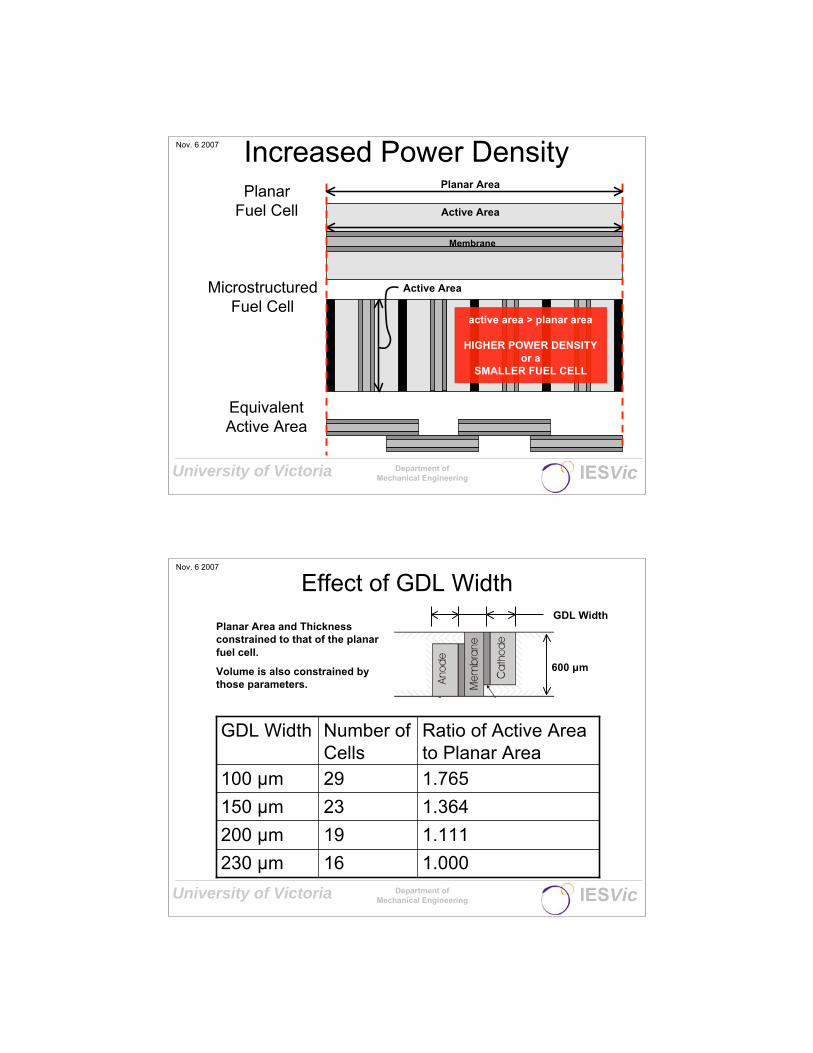
Nov. 6 2007 Increased Power DensityPlanar
Fuel Cell
MicrostructuredFuel Cell
EquivalentActive Area
Active Area
Planar Area
active area > planar area
HIGHER POWER DENSITY
or a
SMALLER FUEL CELL
Active Area
Membrane
University of Victoria Department of
Mechanical Engineering IESVic
Nov. 6 2007
Effect of GDL Width
1.00016230 μm
1.11119200 μm
1.36423150 μm
1.76529100 μm
Ratio of Active Areato Planar Area
Number ofCells
GDL Width
GDL Width
600 μm
Planar Area and Thickness
constrained to that of the planar
fuel cell.
Volume is also constrained by
those parameters.

University of Victoria Department of
Mechanical Engineering IESVic
Nov. 6 2007
Active Area Polarization Curves
For same active area, better
performance with
microstructured fuel cell due
to better humidification
Performance drops with
thinner GDLs due to higher
volumetric heating that
reduces humidity
University of Victoria Department of
Mechanical Engineering IESVic
Nov. 6 2007
Relative Humidity
Relative humidity contours
have shifted downward.
230 μm 200 μm 150 μm 100 μm
Variation in relative humidity due to the diffusion of product water vapour.

University of Victoria Department of
Mechanical Engineering IESVic
Nov. 6 2007
Local Polarization Curves
Bottom of
Cavity
Interface with
the air
High humidity
and membrane
conductivity.
Low humidity
and membrane
dry-out.
University of Victoria Department of
Mechanical Engineering IESVic
Nov. 6 2007
Planar Area Polarization Curves
Performance
improves over entire
polarization curve as
the GDL gets thinner.
Increased efficiency:
Higher voltages for
same power density.
Increased
maximum power
densities.

University of Victoria Department of
Mechanical Engineering IESVic
Nov. 6 2007
Temperature vs. Power Density
7K Drop in
Temperature
Max power
density of the
planar fuel cell.
University of Victoria Department of
Mechanical Engineering IESVic
Nov. 6 2007
Relative Humidity vs.Temperature
Microstructured fuel cell
insulates humidity with the
high aspect ratio GDL.

University of Victoria Department of
Mechanical Engineering IESVic
Nov. 6 2007
Non-Planar Microstructured Fuel Cells
Advantages:Increased active area.Higher maximum power density.Higher efficiency.Reduced operating temperatures.
Note:Performance improves with thinner GDLs.GDL width reduction is limited by oxygenmass transfer, flooding, andmanufacturability.
University of Victoria Department of
Mechanical Engineering IESVic
Nov. 6 2007
Simulations aid design

University of Victoria Department of
Mechanical Engineering IESVic
Nov. 6 2007
Integrated Fuel / Tubular
Designs
Fuel
Fuel Cell
University of Victoria Department of
Mechanical Engineering IESVic
Nov. 6 2007
Micro Solid Oxide Fuel Cell
Anode
Electrolyte
Cathode
4,1001.641(1,000μm)
8,200
2,050
Estimated
Power
(W/lit.)
(VPD)
3.280.5 (500μm)
0.822 (2,000μm)
Surface Area of
the Stack
(m2/litre)
Diameter
(mm)
Partho SarkarAlberta Research Council

University of Victoria Department of
Mechanical Engineering IESVic
Nov. 6 2007
SOFC Single Cells
Anode (Ni/YSZ)
Electrolyte (YSZ)
Cathode (LSM)
(a)Figure 3Anode (Ni/YSZ)
Electrolyte (YSZ)
Cathode (LSM)
(a)Figure 3Anode (Ni/YSZ)
Electrolyte (YSZ)
Cathode (LSM)
Anode (Ni/YSZ)
Electrolyte (YSZ)
Cathode (LSM)
Anode (Ni/YSZ)
Electrolyte (YSZ)
Cathode (LSM)
(a)
University of Victoria Department of
Mechanical Engineering IESVic
Nov. 6 2007
Micro-fuel Cells: Some Issue
Gas Permeability
Crossover
Reactant Distribution
Mechanical properties
Durability
Refuelling

University of Victoria Department of
Mechanical Engineering IESVic
Nov. 6 2007
Diverse System Alternatives
1. DMFC with on-board mixing
2. Passive DMFC
3. Methanol Reformer w/ PEMFC
4. Methanol Reformer w/SOFC
5. SOFC
6. Hydrogen with Hydride Storage
7. Other Fuel (ethanol, ammonia)
8. Biological (enzyme electrolyte)
University of Victoria Department of
Mechanical Engineering IESVic
Nov. 6 2007
Micro Fuel Cells & The Environment
Small/negligible GHG emission reductionsand environmental premium?
For applications >300W the fuel cellcompetes with small IC engines: moresignificant impact
Battery recycling is effective
Why micro-FCs then?