IEEE 848 Standard Procedure For The Determination Of Tthe Ampacity Derating of Fire-Protected Cables
18
Ampacity Ampacity Testing of Fire Protected Raceways Testing of Fire Protected Raceways Kent W. Brown, TVA St Petersburg, FL – March 2008
-
Upload
thorne-derrick -
Category
Technology
-
view
428 -
download
4
Transcript of IEEE 848 Standard Procedure For The Determination Of Tthe Ampacity Derating of Fire-Protected Cables

AmpacityAmpacity Testing of Fire Protected RacewaysTesting of Fire Protected Raceways
Kent W. Brown, TVASt Petersburg, FL – March 2008
Purpose of the Presentation
Provide overview of the test program– Make earlier data available to ICC
» Originally published in IJPG Conference Proceedings
Describe supplemental work– Additional configurations– Approach to defining bounding test specimens
Test results provided in the associated paper– To be included with the Subcommittee D minutes

Cable Ampacities – UG vs Station
Underground– Duct bank– Buried conduit– Direct burial– Known cable locations– “External” factors dominant
» Soil rho» Moisture content
Station– Conduit– Tray
» Maintained spacing» Random filled
– “Internal” factors dominant» Depth of fill» Covers or coatings» Barriers
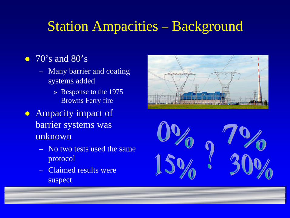
Station Ampacities – Background
70’s and 80’s– Many barrier and coating
systems added» Response to the 1975
Browns Ferry fire
Ampacity impact of barrier systems was unknown– No two tests used the same
protocol– Claimed results were
suspect
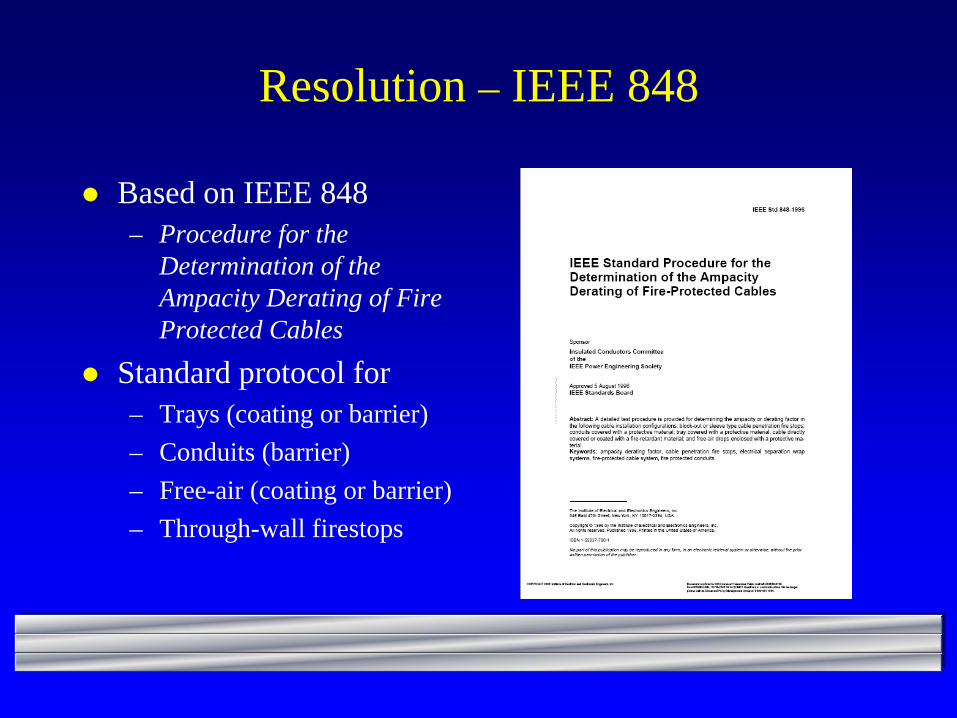
Resolution – IEEE 848
Based on IEEE 848– Procedure for the
Determination of the Ampacity Derating of Fire Protected Cables
Standard protocol for– Trays (coating or barrier)– Conduits (barrier)– Free-air (coating or barrier)– Through-wall firestops

IEEE 848 – Test Setup
Configurations defined– Cable construction– Raceway construction – Raceway fill– Thermocouples
» Placement» Instrumentation accuracy
– “End-effects”– Thermal-breaks at supports T/C Installation in Middle Layer
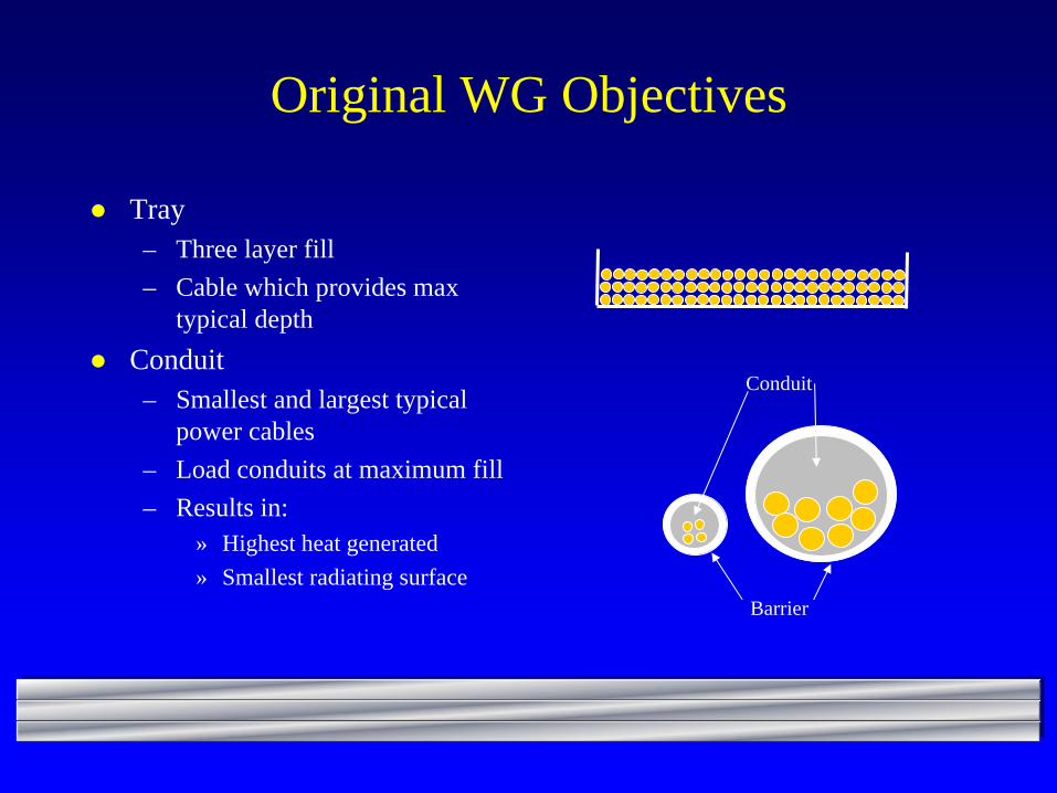
Original WG Objectives
Tray– Three layer fill– Cable which provides max
typical depthConduit– Smallest and largest typical
power cables– Load conduits at maximum fill– Results in:
» Highest heat generated» Smallest radiating surface
Conduit
Barrier
IEEE 848 – Procedure
Baseline current established by testingEquilibrium conditions clearly defined– Time– Allowable temperature drift
» Max 0.2oC/hr rate of change based on a linear regression analysis of data over 60 minute period
– Test current stability
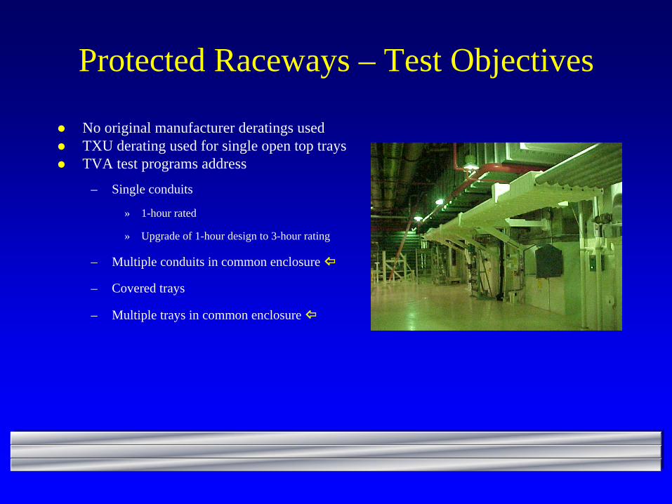
Protected Raceways – Test Objectives
No original manufacturer deratings usedTXU derating used for single open top traysTVA test programs address
– Single conduits
» 1-hour rated
» Upgrade of 1-hour design to 3-hour rating
– Multiple conduits in common enclosure
– Covered trays
– Multiple trays in common enclosure

TVA Test Configurations
Conduit, 1-hr– Baseline (7)– Thermo-Lag (21)– 3M (2)
Boxed conduits, 1-hr– Baseline (3)– Thermo-Lag (5)
Conduit, 3-hr– Baseline (2)– Thermo-Lag (3)
Conformal coating– Baseline (1)– Flamemastic (11)
Tray, 1-hr– Baseline (2)– Thermo-Lag (2)
Tray, 3-hr– Baseline (2)– Thermo-Lag (3)
Air Drop, 1-hr– Baseline (2)– Thermo-Lag (2)
Diversity– Baseline (2)– Alternate loading (9)

TVA Program – Conduit Issues
Conduit– Effect of conduit emissivity– Effect of number of
conductors– Non-standard
configurations– Three-hour systems
Typical Test Enclosure
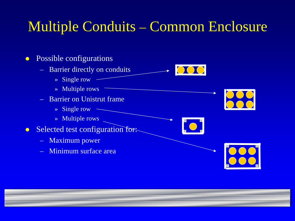
Multiple Conduits – Common Enclosure
Possible configurations– Barrier directly on conduits
» Single row» Multiple rows
– Barrier on Unistrut frame» Single row» Multiple rows
Selected test configuration for: – Maximum power– Minimum surface area
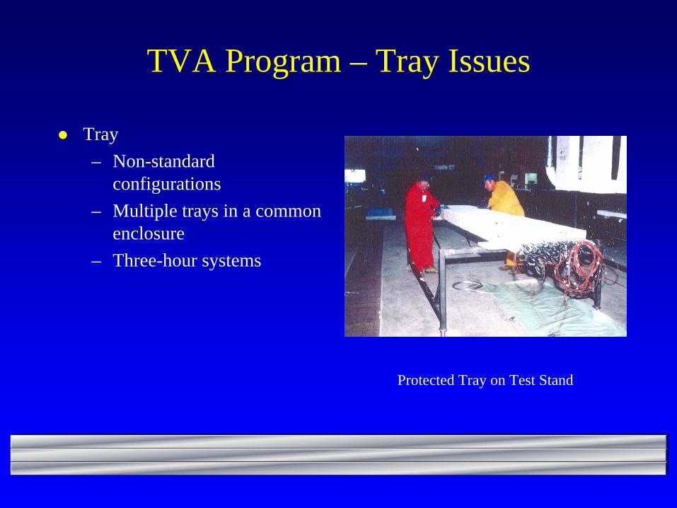
TVA Program – Tray Issues
Tray– Non-standard
configurations– Multiple trays in a common
enclosure– Three-hour systems
Protected Tray on Test Stand
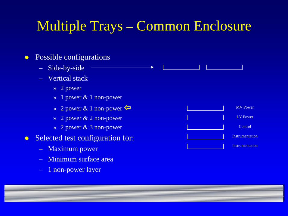
Multiple Trays – Common Enclosure
Possible configurations– Side-by-side– Vertical stack
» 2 power» 1 power & 1 non-power
» 2 power & 1 non-power » 2 power & 2 non-power» 2 power & 3 non-power
Selected test configuration for: – Maximum power– Minimum surface area– 1 non-power layer
Instrumentation
Instrumentation
Control
LV Power
MV Power
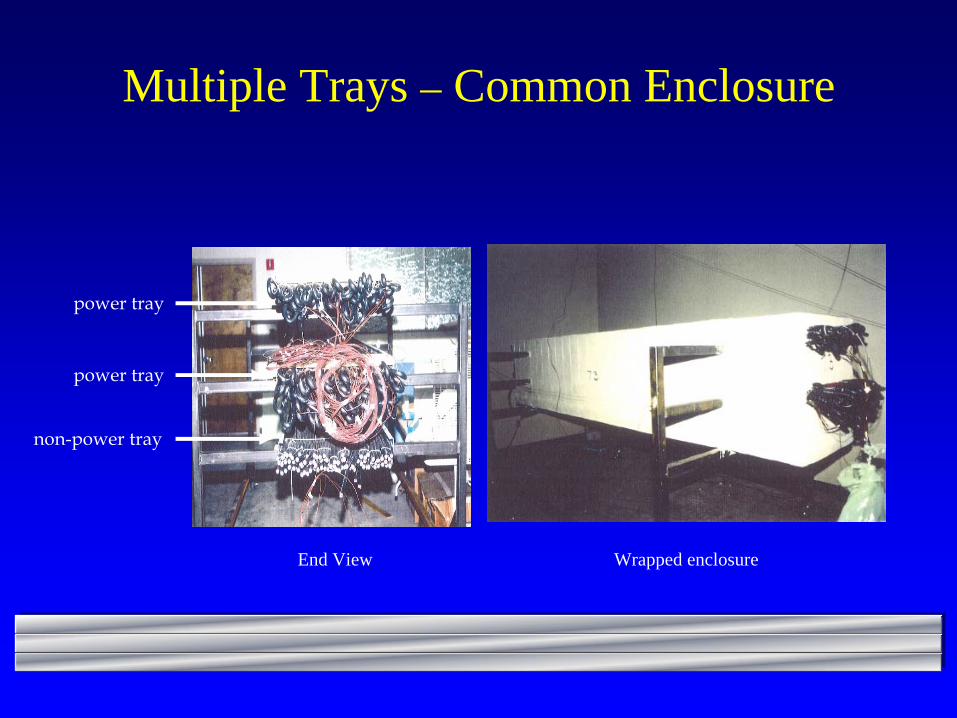
Multiple Trays – Common Enclosure
power tray
power tray
non-power tray
Wrapped enclosureEnd View
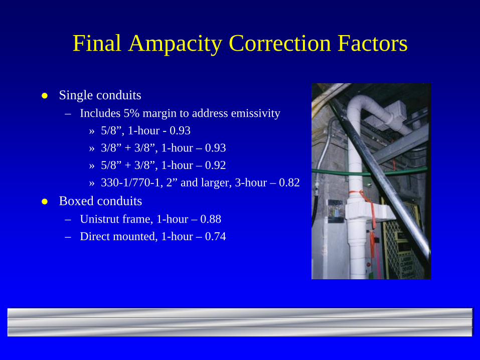
Final Ampacity Correction Factors
Single conduits – Includes 5% margin to address emissivity
» 5/8”, 1-hour - 0.93» 3/8” + 3/8”, 1-hour – 0.93» 5/8” + 3/8”, 1-hour – 0.92» 330-1/770-1, 2” and larger, 3-hour – 0.82
Boxed conduits– Unistrut frame, 1-hour – 0.88– Direct mounted, 1-hour – 0.74
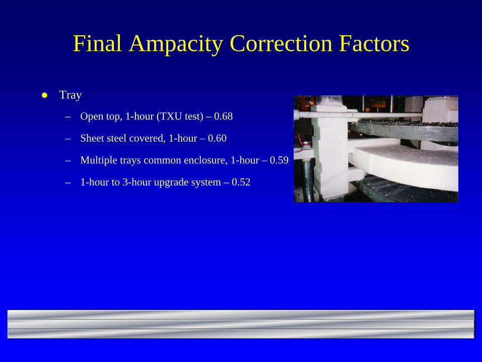
Final Ampacity Correction Factors
Tray
– Open top, 1-hour (TXU test) – 0.68
– Sheet steel covered, 1-hour – 0.60
– Multiple trays common enclosure, 1-hour – 0.59
– 1-hour to 3-hour upgrade system – 0.52

Questions?
Thanks for Your Attention!