Needs and Training in Microelectronics Courses in the MicroElectronics Cloud Alliance
Upload
dnyaneshwarCategory
view
219download
4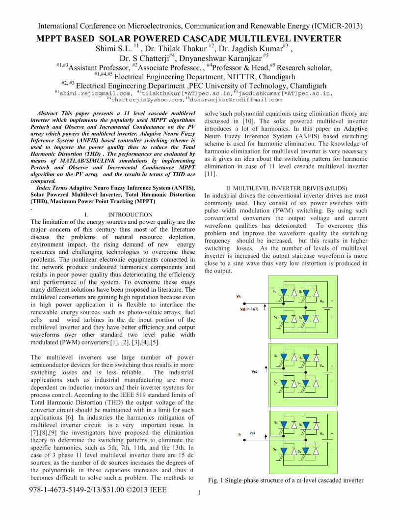
1
Abstract This paper presents a 11 level cascade multilevel inverter which implements the popularly used MPPT algorithms Perturb and Observe and Incremental Conductance on the PV array which powers the multilevel inverter. Adaptive Neuro Fuzzy Inference System (ANFIS) based controller switching scheme is used to improve the power quality thus to reduce the Total Harmonic Distortion (THD) . The performances are evaluated by means of MATLAB/SIMULINK simulations by implementing Perturb and Observe and Incremental Conductance MPPT algorithm on the PV array and the results in terms of THD are compared. Index Terms Adaptive Neuro Fuzzy Inference System (ANFIS), Solar Powered Multilevel Inverter, Total Harmonic Distortion (THD), Maximum Power Point Tracking (MPPT) .
I. INTRODUCTION The limitation of the energy sources and power quality are the major concern of this century thus most of the literature discuss the problems of natural resource depletion, environment impact, the rising demand of new energy resources and challenging technologies to overcome these problems. The nonlinear electronic equipments connected in the network produce undesired harmonics components and results in poor power quality thus deteriorating the efficiency and performance of the system. To overcome these snags many different solutions have been proposed in literature. The multilevel converters are gaining high reputation because even in high power application it is flexible to interface the renewable energy sources such as photo-voltaic arrays, fuel cells and wind turbines in the dc input portion of the multilevel inverter and they have better efficiency and output waveforms over other standard two level pulse width modulated (PWM) converters [1], [2], [3],[4],[5].
The multilevel inverters use large number of power semiconductor devices for their switching thus results in more switching losses and is less reliable. The industrial applications such as industrial manufacturing are more dependent on induction motors and their inverter systems for process control. According to the IEEE 519 standard limits of Total Harmonic Distortion (THD) the output voltage of the converter circuit should be maintained with in a limit for such applications [6]. In industries the harmonics mitigation of multilevel inverter circuit is a very important issue. In [7],[8],[9] the investigators have proposed the elimination theory to determine the switching patterns to eliminate the specific harmonics, such as 5th, 7th, 11th, and the 13th. In case of 3 phase 11 level multilevel inverter there are 15 dc sources, as the number of dc sources increases the degrees of the polynomials in these equations increases and thus it becomes difficult to solve such a problem. The methods to
solve such polynomial equations using elimination theory are discussed in [10]. The solar powered multilevel inverter introduces a lot of harmonics. In this paper an Adaptive Neuro Fuzzy Inference System (ANFIS) based switching scheme is used for harmonic elimination. The knowledge of harmonic elimination for multilevel inverter is very necessary as it gives an idea about the switching pattern for harmonic elimination in case of 11 level cascade multilevel inverter [11].
II. MULTILEVEL INVERTER DRIVES (MLIDS)In industrial drives the conventional inverter drives are most commonly used. They consist of six power switches with pulse width modulation (PWM) switching. By using such conventional converters the output voltage and current waveform qualities has deteriorated. To overcome this problem and improve the waveform quality the switching frequency should be increased, but this results in higher switching losses. As the number of levels of multilevel inverter is increased the output staircase waveform is more close to a sine wave thus very low distortion is produced in the output.
Fig. 1 Single-phase structure of a m-level cascaded inverter
MPPT BASED SOLAR POWERED CASCADE MULTILEVEL INVERTER Shimi S.L. #1 , Dr. Thilak Thakur #2, Dr. Jagdish Kumar#3 ,
Dr. S Chatterji#4, Dnyaneshwar Karanjkar #5 #1,#3Assistant Professor, #2Associate Professor, , #4Professor & Head,#5 Research scholar,
#1,#4,#5 Electrical Engineering Department, NITTTR, Chandigarh #2, #3 Electrical Engineering Department ,PEC University of Technology, Chandigarh
#[email protected], #2tilakthakur[*AT]pec.ac.in,#3jagdishkumar[*AT]pec.ac.in, #[email protected],#[email protected]
978-1-4673-5149-2/13/$31.00 ©2013 IEEE
International Conference on Microelectronics, Communication and Renewable Energy (ICMiCR-2013)
2
The cascaded MLID is the main focus of this paper. The Fig. 1 shows the single-phase structure of a m-level cascaded inverter. ∑ cos cos, , …cos cos cos sin (1)
III. PV MODELINGModeling of a solar cell is done by connecting a current source in parallel with an inverted diode along with a series and a parallel resistance as shown in Fig.2. The series resistance is due to hindrance in the path of flow of electrons from n to p junction and parallel resistance is due to the leakage current. The single diode model was adopted for simulating the photo-voltaic (PV) module under different irradiance and temperature levels as shown in Fig. 2 [13]. The modeling of the photo-voltaic PV cell was done in MATLAB/SIMULINK by writing the code in the embedded block. The photo-voltaic (PV) cell subsystems were modeled and connected to the 11 level cascade multilevel inverter.
Fig. 2 Single diode model of a PV cell
In literature a number of approaches and models can be found to analyze the behavior of PVs [14-16]. The PV cell model used in this work is based on the single diode cell. The VI characteristics ( in green) of a typical solar cell are as shown in the Fig. 3.
Fig. 3 V-I and P-V characteristics curve of photovoltaic cell When the voltage and the current characteristics are multiplied we get the P-V characteristics (in blue) as shown in Fig. 3.
The point highlighted as maximum power point at which the panel power output is maximum [17]. The equation (2 ) is the basic equation for the photovoltaic current.
1 (2)
where, Ipv : photovoltaic current; I0 : saturation current Rs : equivalent series resistance; Vt : thermal voltage Rp : equivalent parallel resistance; a : diode ideality constant
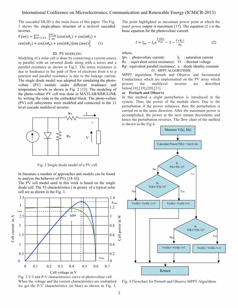
IV. MPPT ALGORITHMSMPPT algorithms Perturb and Observe and Incremental Conductance which are implemented on the PV array which powers the multilevel inverter are described below[18],[19],[20],[21]. a) Perturb and ObserveIn this method a slight perturbation is introduced in the system. Thus, the power of the module alters. Due to the perturbation if the power enhances, then the perturbation is carried on in the same direction. After the maximum power is accomplished, the power at the next instant decrements and hence the perturbation reverses. The flow chart of the method is shown in the Fig 4.
Fig. 4 Flowchart for Perturb and Observe MPPT Algorithms
Rs
Rs
+
V
I
Cell voltage in V
NoYes
Yes
Yes
No
No
Is V(k)=V(k-1)?
Vref(k)= Vref(k-1)+C Vref(k)= Vref(k-1)-C
Vref(k)= Vref(k-1)-C Vref(k)= Vref(k-1)+C
Return
Is V(k)=V(k-1)?
Measure V(k), I(k)
Calculate Power P(k)= V(k)X I(k)
Is P(k)>P(k-1)?
0
IMPP
Cel
l pow
er in
W
0.7
3.5
3
2.5
2
1.5
1
0.5
1.4
1.2
1
0.8
0.6
0.4
0.2
0 0.60.5 0.4 0.3 0.2 0.1 0
MPP
Voc
PMPP
Cel
l cur
rent
in
A
International Conference on Microelectronics, Communication and Renewable Energy (ICMiCR-2013)
3
As in this method only one voltage and current sensor is used the error due to change in irradiance is introduced.
b)Incremental Conductance MethodIncremental conductance method senses both the voltage and current of the PV array simultaneously thus the error due to change in irradiance is eradicated. At MPP the slope of the PV curve is 0.
(dP/dV)MPP=d(VI)/dV 0=I+VdI/dVMPP dI/dVMPP = - I/V ------------------------------------- (3)
The left hand side of equation (3) is the instantaneous conductance of the solar panel. The instantaneous conductance equals the conductance of the PV array then MPP is reached. This method is more complex and the cost of implementation is also high and this method is suitable for a highly elaborated system.
V. ANFIS (Adaptive Neuro Fuzzy Inference System) Intelligent control is the best alternative to conventional control schemes. The unsure or unknown variations in plant parameters can be dealt more effectively by using artificial intelligent (AI) techniques such as fuzzy logic and neural network. Thus the control system performance can be improved. The nodes in the multi-layer feed forward network performs a particular function on the incoming signals. The links in the adaptive network just indicate the signal flow direction [22, 23].
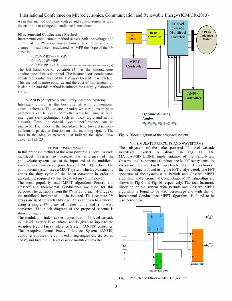
VI. PROPOSED DESIGNIn this proposed method of the solar powered 11 level cascade multilevel inverter, to increase the efficiency of the photovoltaic system used at the input end of the multilevel inverter maximum power point tracking (MPPT) is done. The photovoltaic system uses a MPPT system which automatically varies the duty cycle of the boost converter in order to generate the required voltage to extract maximum power. The most popularly used MPPT algorithms Perturb and Observe and Incremental Conductance are used for this purpose. The dc supply from the PV array to each H-bridge of the multilevel inverter should be isolated. Thus separate PV arrays are used for each H-bridge. This can even be achieved using a single PV array of higher rating and a forward converter. The block diagram of the proposed scheme is shown in figure 6. The modulation index at the output bus of 11 level cascade multilevel inverter is calculated and is given as input to the Adaptive Neuro Fuzzy Inference System (ANFIS) controller. The Adaptive Neuro Fuzzy Inference System (ANFIS) controller chooses the optimized firing angles 1, 2, 3, 4 and 5 and fires the 11 level cascade multilevel inverter.
Fig. 6. Block diagram of the proposed system
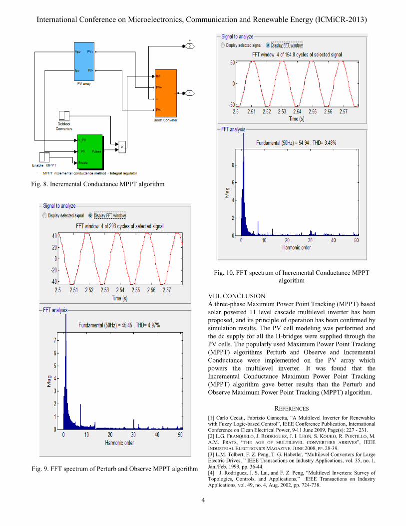
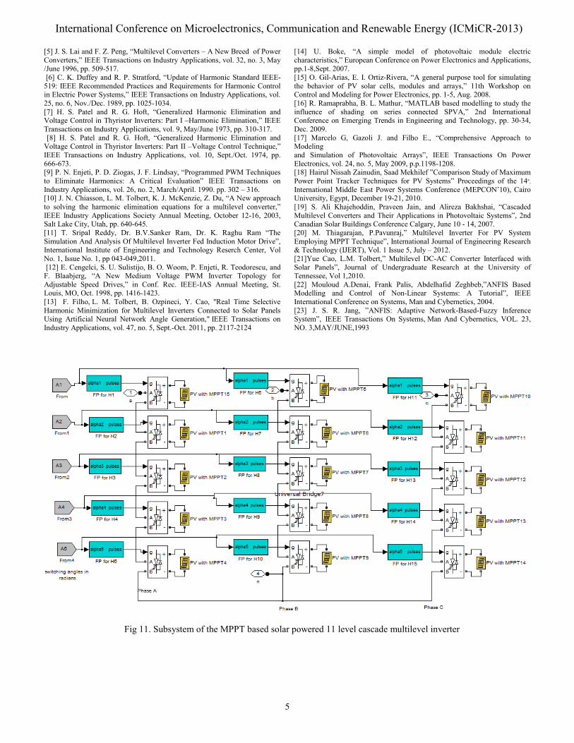
VII. SIMULATED CIRCUITS AND WAVEFORMSThe subsystem of the solar powered 11 level cascade multilevel inverter is shown in Fig 11. The MATLAB/SIMULINK implementation of the Perturb and Observe and Incremental Conductance MPPT subsystems are shown in Fig 7 and Fig 8 respectively. The FFT spectrum of the line voltage is found using the FFT analysis tool. The FFT spectrum of the system with Perturb and Observe MPPT algorithm and Incremental Conductance MPPT algorithm are shown in Fig 9 and Fig 10 respectively. The total harmonic distortion of the system with Perturb and Observe MPPT algorithm is found to be 4.97 percentage and with that of Incremental Conductance MPPT algorithm is found to be 3.48 percentage.
Fig. 7. Perturb and Observe MPPT algorithm
Optimized Firing Angles
3 Phase Induction
Motor
ANFIS Controller
PV Array
MPPT Controller
11 level cascade
Multilevel Inverter
Boost Converter
International Conference on Microelectronics, Communication and Renewable Energy (ICMiCR-2013)
4
Fig. 8. Incremental Conductance MPPT algorithm
Fig. 9. FFT spectrum of Perturb and Observe MPPT algorithm
Fig. 10. FFT spectrum of Incremental Conductance MPPT algorithm
VIII. CONCLUSIONA three-phase Maximum Power Point Tracking (MPPT) based solar powered 11 level cascade multilevel inverter has been proposed, and its principle of operation has been confirmed by simulation results. The PV cell modeling was performed and the dc supply for all the H-bridges were supplied through the PV cells. The popularly used Maximum Power Point Tracking (MPPT) algorithms Perturb and Observe and Incremental Conductance were implemented on the PV array which powers the multilevel inverter. It was found that the Incremental Conductance Maximum Power Point Tracking (MPPT) algorithm gave better results than the Perturb and Observe Maximum Power Point Tracking (MPPT) algorithm.
REFERENCES [1] Carlo Cecati, Fabrizio Ciancetta, “A Multilevel Inverter for Renewables with Fuzzy Logic-based Control”, IEEE Conference Publication, International Conference on Clean Electrical Power, 9-11 June 2009, Page(s): 227 - 231. [2] L.G. FRANQUELO, J. RODRIGUEZ, J. I. LEON, S. KOUKO, R. PORTILLO, M. A.M. PRATS, “THE AGE OF MULTILEVEL CONVERTERS ARRIVES”, IEEE INDUSTRIAL ELECTRONICS MAGAZINE, JUNE 2008, PP. 28-39. [3] L.M. Tolbert, F. Z. Peng, T. G. Habetler, “Multilevel Converters for Large Electric Drives, ” IEEE Transactions on Industry Applications, vol. 35, no. 1, Jan./Feb. 1999, pp. 36-44. [4] J. Rodriguez, J. S. Lai, and F. Z. Peng, “Multilevel Inverters: Survey of Topologies, Controls, and Applications,” IEEE Transactions on Industry Applications, vol. 49, no. 4, Aug. 2002, pp. 724-738.
International Conference on Microelectronics, Communication and Renewable Energy (ICMiCR-2013)
5
[5] J. S. Lai and F. Z. Peng, “Multilevel Converters – A New Breed of Power Converters,” IEEE Transactions on Industry Applications, vol. 32, no. 3, May /June 1996, pp. 509-517. [6] C. K. Duffey and R. P. Stratford, “Update of Harmonic Standard IEEE-519: IEEE Recommended Practices and Requirements for Harmonic Control in Electric Power Systems,” IEEE Transactions on Industry Applications, vol. 25, no. 6, Nov./Dec. 1989, pp. 1025-1034. [7] H. S. Patel and R. G. Hoft, “Generalized Harmonic Elimination and Voltage Control in Thyristor Inverters: Part I –Harmonic Elimination,” IEEE Transactions on Industry Applications, vol. 9, May/June 1973, pp. 310-317.
[8] H. S. Patel and R. G. Hoft, “Generalized Harmonic Elimination and Voltage Control in Thyristor Inverters: Part II –Voltage Control Technique,” IEEE Transactions on Industry Applications, vol. 10, Sept./Oct. 1974, pp. 666-673. [9] P. N. Enjeti, P. D. Ziogas, J. F. Lindsay, “Programmed PWM Techniques to Eliminate Harmonics: A Critical Evaluation” IEEE Transactions on Industry Applications, vol. 26, no. 2, March/April. 1990. pp. 302 – 316. [10] J. N. Chiasson, L. M. Tolbert, K. J. McKenzie, Z. Du, “A New approach to solving the harmonic elimination equations for a multilevel converter,” IEEE Industry Applications Society Annual Meeting, October 12-16, 2003, Salt Lake City, Utah, pp. 640-645. [11] T. Sripal Reddy, Dr. B.V.Sanker Ram, Dr. K. Raghu Ram “The Simulation And Analysis Of Multilevel Inverter Fed Induction Motor Drive”, International Institute of Engineering and Technology Reserch Center, Vol No. 1, Issue No. 1, pp 043-049,2011. [12] E. Cengelci, S. U. Sulistijo, B. O. Woom, P. Enjeti, R. Teodorescu, and F. Blaabjerg, “A New Medium Voltage PWM Inverter Topology for Adjustable Speed Drives,” in Conf. Rec. IEEE-IAS Annual Meeting, St. Louis, MO, Oct. 1998, pp. 1416-1423. [13] F. Filho, L. M. Tolbert, B. Ozpineci, Y. Cao, "Real Time Selective Harmonic Minimization for Multilevel Inverters Connected to Solar Panels Using Artificial Neural Network Angle Generation," IEEE Transactions on Industry Applications, vol. 47, no. 5, Sept.-Oct. 2011, pp. 2117-2124
[14] U. Boke, “A simple model of photovoltaic module electric characteristics,” European Conference on Power Electronics and Applications, pp.1-8,Sept. 2007. [15] O. Gil-Arias, E. I. Ortiz-Rivera, “A general purpose tool for simulating the behavior of PV solar cells, modules and arrays,” 11th Workshop on Control and Modeling for Power Electronics, pp. 1-5, Aug. 2008. [16] R. Ramaprabha, B. L. Mathur, “MATLAB based modelling to study the influence of shading on series connected SPVA,” 2nd International Conference on Emerging Trends in Engineering and Technology, pp. 30-34, Dec. 2009. [17] Marcelo G, Gazoli J. and Filho E., “Comprehensive Approach to Modeling and Simulation of Photovoltaic Arrays”, IEEE Transactions On Power Electronics, vol. 24, no. 5, May 2009, p.p.1198-1208. [18] Hairul Nissah Zainudin, Saad Mekhilef ”Comparison Study of Maximum Power Point Tracker Techniques for PV Systems” Proceedings of the 14th,
International Middle East Power Systems Conference (MEPCON’10), Cairo University, Egypt, December 19-21, 2010. [19] S. Ali Khajehoddin, Praveen Jain, and Alireza Bakhshai, “Cascaded Multilevel Converters and Their Applications in Photovoltaic Systems”, 2nd Canadian Solar Buildings Conference Calgary, June 10 - 14, 2007. [20] M. Thiagarajan, P.Pavunraj,” Multilevel Inverter For PV System Employing MPPT Technique”, International Journal of Engineering Research & Technology (IJERT), Vol. 1 Issue 5, July – 2012. [21]Yue Cao, L.M. Tolbert,” Multilevel DC-AC Converter Interfaced with Solar Panels”, Journal of Undergraduate Research at the University of Tennessee, Vol 1,2010. [22] Mouloud A.Denai, Frank Palis, Abdelhafid Zeghbeb,”ANFIS Based Modelling and Control of Non-Linear Systems: A Tutorial”, IEEE International Conference on Systems, Man and Cybernetics, 2004. [23] J. S. R. Jang, ”ANFIS: Adaptive Network-Based-Fuzzy Inference System”, IEEE Transactions On Systems, Man And Cybernetics, VOL. 23, NO. 3,MAY/JUNE,1993
Fig 11. Subsystem of the MPPT based solar powered 11 level cascade multilevel inverter
International Conference on Microelectronics, Communication and Renewable Energy (ICMiCR-2013)