IDS-NF Mercury System Overview Van Graves IDS-NF 5 th Plenary Meeting April 9, 2010.
19
IDS-NF Mercury System Overview Van Graves IDS-NF 5 th Plenary Meeting April 9, 2010
-
Upload
coleen-roberts -
Category
Documents
-
view
213 -
download
0
Transcript of IDS-NF Mercury System Overview Van Graves IDS-NF 5 th Plenary Meeting April 9, 2010.

IDS-NF Mercury System Overview
Van Graves
IDS-NF 5th Plenary MeetingApril 9, 2010

2 Managed by UT-Battellefor the U.S. Department of Energy Mercury System Overview IDS-NF 6 Apr 2010
Background
• MERIT demonstrated Hg jet target is feasible for Neutrino Factory• Goal now is to further develop the conceptual design
for Reference Design Report– ORNL investigating mercury system design to identify
operational or functional issues
NF Mercury System Concept
3 Managed by UT-Battellefor the U.S. Department of Energy Mercury System Overview IDS-NF 6 Apr 2010
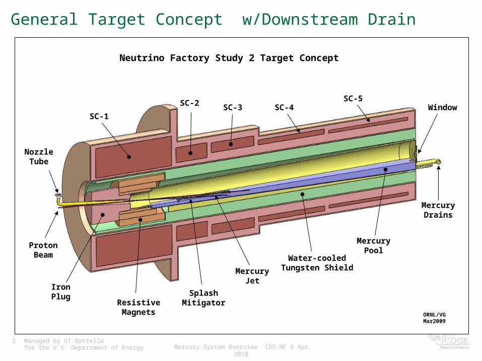
IronPlug
ProtonBeam
NozzleTube
SC-1
SC-2 SC-3 SC-4SC-5
Window
MercuryDrains
MercuryPool
Water-cooledTungsten ShieldMercury
Jet
ResistiveMagnets
Neutrino Factory Study 2 Target Concept
ORNL/VGMar2009
SplashMitigator
General Target Concept w/Downstream Drain

4 Managed by UT-Battellefor the U.S. Department of Energy Mercury System Overview IDS-NF 6 Apr 2010
Cryostat Upstream End
IronPlug
Proton Beam(67 mrad)
NozzleTube
SC-1SC-2 SC-3
MercuryPool
Water-cooledTungsten Shield
Mercury Jet(100 mrad)
ResistiveMagnets
SplashMitigator

5 Managed by UT-Battellefor the U.S. Department of Energy Mercury System Overview IDS-NF 6 Apr 2010
Front View
• Includes slope for Hg drainage downstream• Mechanical issues
between nozzle and beam• Splash mitigation
scheme incorporated• Relatively thin beam
stop (Hg depth)

6 Managed by UT-Battellefor the U.S. Department of Energy Mercury System Overview IDS-NF 6 Apr 2010
Cryostat Downstream End
• Window becomes a liquid barrier• Mercury pool serves
as additional SC shielding• Cryostat becomes
trapped by mercury nozzle and drain piping
SC-5
Window
OverflowDrain
ValvedDrain
TungstenShielding

7 Managed by UT-Battellefor the U.S. Department of Energy Mercury System Overview IDS-NF 6 Apr 2010
Front Drain Views
• Investigated possibility of having the Hg drain from the nozzle end of the cryostat

8 Managed by UT-Battellefor the U.S. Department of Energy Mercury System Overview IDS-NF 6 Apr 2010
Mercury Drain Tungsten Shield
Beam Window
Front Drain Cross Section View
• Mercury Chamber extends forward under resistive magnets• Allows the mercury exiting the vessel to flow out the front of the
cryostat• Puts beam window in middle of cryostat

9 Managed by UT-Battellefor the U.S. Department of Energy Mercury System Overview IDS-NF 6 Apr 2010
Flow Loop Review
• 1 cm dia nozzle, 20 m/s jet requires 1.57 liter/sec mercury flow (94.2 liter/min, 24.9 gpm).• MERIT experiment showed that a pump discharge
pressure of ~40 bar gauge required to produce the desired jet.– Reference: SNS nominal flow 1440 liter/min (380 gpm), 7 bar
gauge pump discharge pressure, ~1400 liters total Hg inventory
• Basic flow schemePump → Nozzle → Jet/Beam Dump → Heat Exchanger → Pump

10 Managed by UT-Battellefor the U.S. Department of Energy Mercury System Overview IDS-NF 6 Apr 2010
Hg Flow
• Minimize pressure drops through piping by increasing diameter– 2" nozzle supply piping
transitioning to 1 cm nozzle
• Actual NF Hg inventory may reach SNS volumes– ~500 liters in the half-
length beam dump shown
Overflow Mercury Drain
Mercury Pump
Gravity Drain Flow Control Valve
Storage Tank
Heat Exchanger
Beam Dump

11 Managed by UT-Battellefor the U.S. Department of Energy Mercury System Overview IDS-NF 6 Apr 2010
Heat Removal
• From Study 2, the mercury jet/pool receive < 10% of beam energy; 50-60% goes into WC shielding (~2.4MW for 4MW beam)– Currently assumed to be WC spheres cooled by water
– Much larger heat exchanger needed to cool shielding
• Considering that both W and WC must be water-cooled, their effective densities will approach that of Hg.• Consequently, IF a Hg target is selected, the infrastructure will be
in place to support use of Hg as a solenoid shield.– Would probably be a separate loop due to vastly different flow/pressure
requirements, but could share a storage tank
Element/Compound Density (g/cm^3)
Hg 13.5
W 19.3
WC 15.8Mercury Drain Tungsten Shield
Beam Window

12 Managed by UT-Battellefor the U.S. Department of Energy Mercury System Overview IDS-NF 6 Apr 2010
Decay Channel Cryostats
Core Vessel Mercury Process
Hot Cell
Main Cryostat (Target Region)
NF Target Building Development Work
• Using Study 2 concept as a starting point• Goal is to produce RDR
Target Facility concept with cost estimate

13 Managed by UT-Battellefor the U.S. Department of Energy Mercury System Overview IDS-NF 6 Apr 2010
Potential Future Mercury Work
• Systems Engineering– Mercury loop refinement and design for remote maintenance– Target/beam dump remote maintenance– Beam window remote replacement– Cryostat/magnet design integrated with mercury jet and beam
dump– Facility development
• Hardware studies– Continuous jet flow loop• Nozzle studies, beam dump experiments
– Tungsten shielding• Thermal / hydraulic studies

14 Managed by UT-Battellefor the U.S. Department of Energy Mercury System Overview IDS-NF 6 Apr 2010
Implications of Using a Mercury Target
• http://www.hep.princeton.edu/~mcdonald/mumu/target/graves/graves_121708.pdf

15 Managed by UT-Battellefor the U.S. Department of Energy Mercury System Overview IDS-NF 6 Apr 2010
SNS Target Building Layout
Target
Target Service Bay (Hot Cell)Instrument Ports (9 ea)
Instrument Ports (9 ea)
Proton Beam

16 Managed by UT-Battellefor the U.S. Department of Energy Mercury System Overview IDS-NF 6 Apr 2010
SNS Target Support Utilities
Water Cooling Loop
Primary & SecondaryConfinement Exhaust
LLLW
TritiumRemoval
Carbon Filters
17 Managed by UT-Battellefor the U.S. Department of Energy Mercury System Overview IDS-NF 6 Apr 2010
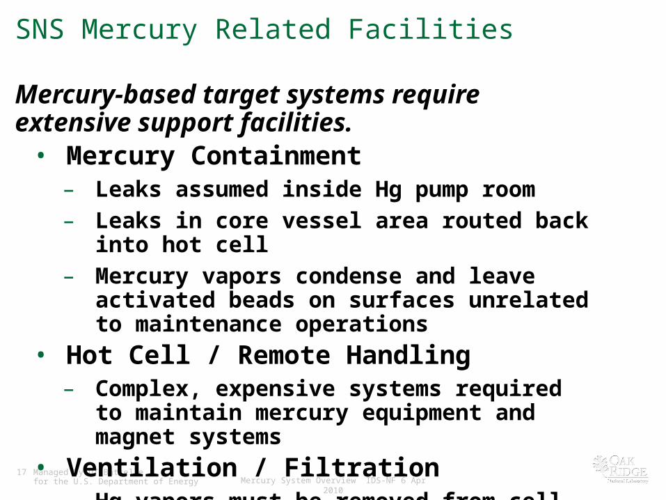
SNS Mercury Related Facilities
Mercury-based target systems require extensive support facilities.• Mercury Containment– Leaks assumed inside Hg pump room– Leaks in core vessel area routed back into hot cell– Mercury vapors condense and leave activated beads on
surfaces unrelated to maintenance operations• Hot Cell / Remote Handling– Complex, expensive systems required to maintain
mercury equipment and magnet systems• Ventilation / Filtration– Hg vapors must be removed from cell exhaust & process
off-gas prior to HEPA filtration

18 Managed by UT-Battellefor the U.S. Department of Energy Mercury System Overview IDS-NF 6 Apr 2010
SNS Mercury Related Facilities Cont’d
• Waste Handling– In US, mercury treatment and disposal governed by the Resource
Conservation and Recovery Act (RCRA) (hazardous waste)– Radioactive mercury imposes additional requirements
• In the US, this type of waste is called “mixed waste”.• Disposal options are VERY limited.
• Water Cooling System– Process mercury cooled with secondary water system
– Hands-on maintenance after beam-off
• Mercury Target Safety Considerations– Accident & hazard analyses required to ensure protection of workers /
public / environment
• Operational Considerations– Maintenance of Hg systems complex, long downtimes expected
– Maintenance of remote tooling is significant operational cost

19 Managed by UT-Battellefor the U.S. Department of Energy Mercury System Overview IDS-NF 6 Apr 2010
Summary
• Work continues towards development of mercury-jet-based target system for Neutrino Factory• Several engineering challenges remain in the design of
a mercury nozzle / beam dump• SNS experience highlights the realities and challenges
of using a mercury target


![IDS-NF Accelerator Baseline The Neutrino Factory [1, 2] based on the muon storage ring will be a precision tool to study the neutrino oscillations.It may.](https://static.fdocuments.in/doc/165x107/5a4d1ad97f8b9ab0599740ae/ids-nf-accelerator-baseline-the-neutrino-factory-1-2-based-on-the-muon-storage.jpg)