
NF-8601/ NF-8601A/ NF-8601W Instruction Manual … · Pa en ted producs, o unterfeiting ......
16
ORIGINAL AUTHENTIC d pro d nte uc te ts a , P ng no eiti t a rf l te lo n w u e o d C ORIGINAL AUTHENTIC REV1.0 Your excellent helper in cable test! Your excellent helper in cable test! NF-8601/ NF-8601A/ NF-8601W Instruction Manual Cable Length Tester Instruction Manual Cable Length Tester NF-8601/ NF-8601A/ NF-8601W NF-8601
-
Upload
nguyenkien -
Category
Documents
-
view
374 -
download
10
Transcript of NF-8601/ NF-8601A/ NF-8601W Instruction Manual … · Pa en ted producs, o unterfeiting ......
ORIGINAL AUTHENTIC
d prodnte ucte tsa ,Png noeiti t arf lte lon wu eo dC
ORIGINAL AUTHENTIC
REV1.0
Your excellent helper in cable test!
Your excellent helper in cable test!
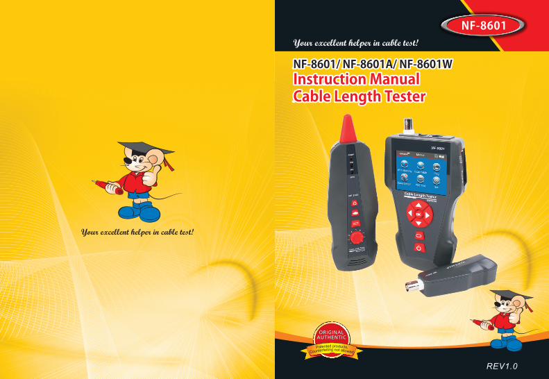
NF-8601/ NF-8601A/ NF-8601WInstruction ManualCable Length Tester Instruction ManualCable Length Tester
NF-8601/ NF-8601A/ NF-8601W
NF-8601
CONTENTS
Your excellent helper in cable test! Your excellent helper in cable test!
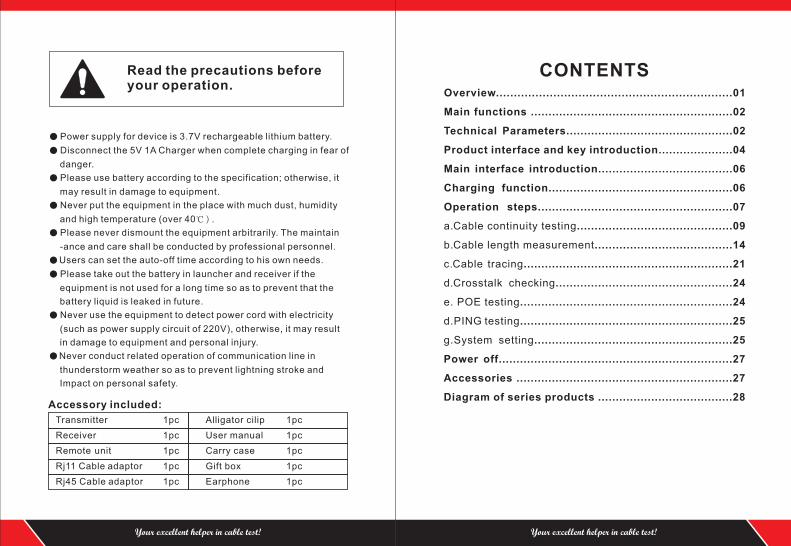
● Power supply for device is 3.7V rechargeable lithium battery.
● Disconnect the 5V 1A Charger when complete charging in fear of
danger.
● Please use battery according to the specification; otherwise, it
may result in damage to equipment.
● Never put the equipment in the place with much dust, humidity
and high temperature (over 40℃).
● Please never dismount the equipment arbitrarily. The maintain
-ance and care shall be conducted by professional personnel.
● Users can set the auto-off time according to his own needs.
● Please take out the battery in launcher and receiver if the
equipment is not used for a long time so as to prevent that the
battery liquid is leaked in future.
● Never use the equipment to detect power cord with electricity
(such as power supply circuit of 220V), otherwise, it may result
in damage to equipment and personal injury.
● Never conduct related operation of communication line in
thunderstorm weather so as to prevent lightning stroke and
Impact on personal safety.
Read the precautions before your operation.
Transmitter 1pc
Receiver 1pc
Remote unit 1pc
Rj11 Cable adaptor 1pc
Rj45 Cable adaptor 1pc
Accessory included:
Alligator cilip 1pc
User manual 1pc
Carry case 1pc
Gift box 1pc
Earphone 1pc
Overview..................................................................01
Main functions .........................................................02
Technical Parameters...............................................02
Product interface and key introduction.....................04
Main interface introduction......................................06
Charging function....................................................06
Operation steps........ ...........................................07
a.Cable continuity testing............................................09
b.Cable length measurement.......................................14
c.Cable tracing...........................................................21
d.Crosstalk checking..................................................24
e. POE testing............................................................24
d.PING testing............................................................25
g.System setting........................................................25
Power off..................................................................27
Accessories .............................................................27
Diagram of series products ......................................28
....
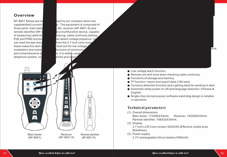
Overview
NF-8601 Series are newly developed by our company which are
capableofanti current interference . The equipment is composed of
three parts: main tester (NF-8601-M), receiver (NF-8601-S) and
remote identifier (NF-8601-R). It is a multifunction device, capable
of measuring cable length, cable tracing, cable continuity testing,
PoE and PING functions, also it can detect voltage presence. Users
can read the test results visually from the 3.7 inch color screen. All
these make this item be as a practical tool for low voltage system
installation and maintenance technicians of communication circuits
and comprehensive wiring circuits. It is widely used in the fields like
telephone system, computer networks and other metal lead circuits.
Remote identifier (NF-8601-R)
Main tester (NF-8601)
Receiver (NF-8601-S)
● Capable to test open, short, cross connection, reverse, and
broken wire positioning with M-S, M-R method.
● To perform crosstalk test on network cable to solve the potential
problem of slow speed.
● To quickly find the targeted cable without stripping isolation
among unknown cables.
● Measure length of network cable, coaxial cable, telephone cable
and USB cable up to 2000m, no connection of remote unit.
● To trace cable on exchanger or Router without current interference.
● Locate breakage and short position accurately.
● Detect PoE presence.
● PING Testing
Main functions
Technical parameters
01 02Your excellent helper in cable test! Your excellent helper in cable test!
NF-8601
OK
Wire Mapping Scan Cable
Set
Ping
Menu
POE Test
Power
CHG
NCV
SCAN
NF-8601
SET
Low voltage alarm function.
● Remote unit with tone when checking cable continuity.
● Functions of storage and memory.
● TF function: import and export data.(160 sets)
● Currency detection function and Lighting lamp for working in dark.
● Automatic delay power on-off and language selection: Chinese &
English.
● Single chip microprocessor software watchdog design is reliable
in operation.
●
Benefits
(1). Overall dimensions
Main tester: 173X92X34mm; Receiver: 183X58X35mm
Remote identifier: 106X32X30mm.
(2). Display
3.7 inch LCD Color screen:320X240 (Effective visible area
60X45mm).
(3). Power supply
3.7V rechargeable lithium battery1800mAh
Cable Length
RECEIVER
Cable Length Tester
NF
-86
01
WIR
EM
AP
NF-8601
OK
Wire Mapping Scan Cable
Set
Ping
Menu
POE TestCable Length
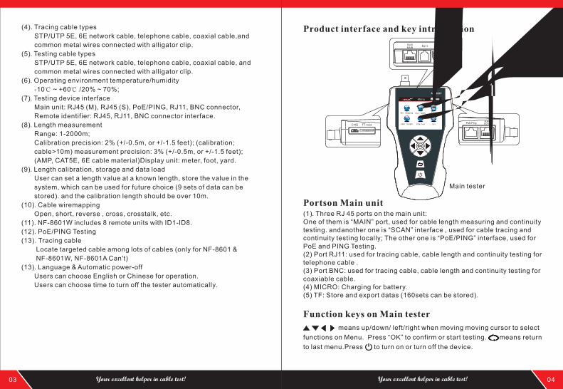
Product interface and key introduction
Main tester
BNCRJ45MAIN
RJ11
RJ45SCANPoE/Ping
CHG FT Card
(4). Tracing cable types
STP/UTP 5E, 6E network cable, telephone cable, coaxial cable,and
common metal wires connected with alligator clip.
(5). Testing cable types
STP/UTP 5E, 6E network cable, telephone cable, coaxial cable, and
common metal wires connected with alligator clip.
(6). Operating environment temperature/humidity
-10℃ ~ +60℃ /20% ~ 70%;
(7). Testing device interface
Main unit: RJ45 (M), RJ45 (S), PoE/PING, RJ11, BNC connector,
Remote identifier: RJ45, RJ11, BNC connector interface.
(8). Length measurement
Range: 1-2000m;
Calibration precision: 2% (+/-0.5m, or +/-1.5 feet); (calibration;
cable>10m) measurement precision: 3% (+/-0.5m, or +/-1.5 feet);
(AMP, CAT5E, 6E cable material)Display unit: meter, foot, yard.
(9). Length calibration, storage and data load
User can set a length value at a known length, store the value in the
system, which can be used for future choice (9 sets of data can be
stored). and the calibration length should be over 10m.
(10). Cable wiremapping
Open, short, reverse , cross, crosstalk, etc.
(11). NF-8601W includes 8 remote units with ID1-ID8.
(12). PoE/PING Testing
(13). Tracing cable
Locate targeted cable among lots of cables (only for NF-8601 &
NF-8601W, NF-8601A Can't)
(13). Language & Automatic power-off
Users can choose English or Chinese for operation.
Users can choose time to turn off the tester automatically.
03 04Your excellent helper in cable test! Your excellent helper in cable test!
(1). Three RJ 45 ports on the main unit: One of them is “MAIN” port, used for cable length measuring and continuity testing. andanother one is “SCAN” interface , used for cable tracing and continuity testing locally; The other one is “PoE/PING” interface, used for PoE and PING Testing. (2) Port RJ11: used for tracing cable, cable length and continuity testing for telephone cable .(3) Port BNC: used for tracing cable, cable length and continuity testing for coaxiable cable.(4) MICRO: Charging for battery. (5) TF: Store and export datas (160sets can be stored).
Portson Main unit
Function keys on Main tester
means up/down/ left/right when moving moving cursor to select
functions on Menu. Press “OK” to confirm or start testing. means return
to last menu.Press to turn on or turn off the device.
Po
we
r
CH
G
NC
V
SC
AN
NF
-86
01
SE
T
RECEIV
ER
Cable
Length
Teste
r
Receiver
Remote identifier
CH
G
05 06Your excellent helper in cable test! Your excellent helper in cable test!
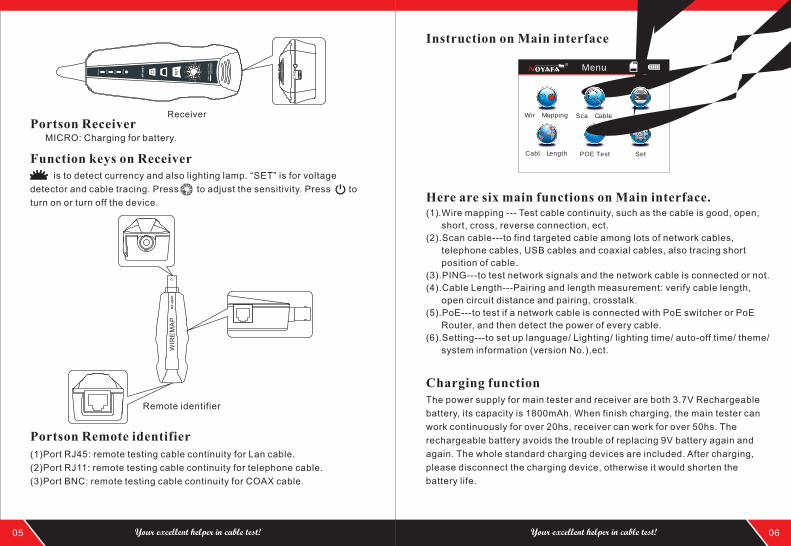
MICRO: Charging for battery.
Portson Receiver
Function keys on Receiver is to detect currency and also lighting lamp. “SET” is for voltage
detector and cable tracing. Press to adjust the sensitivity. Press to
turn on or turn off the device.
(1)Port RJ45: remote testing cable continuity for Lan cable.
(2)Port RJ11: remote testing cable continuity for telephone cable.
(3)Port BNC: remote testing cable continuity for COAX cable.
Portson Remote identifier
Instruction on Main interface
Here are six main functions on Main interface.(1).Wire mapping --- Test cable continuity, such as the cable is good, open,
short, cross, reverse connection, ect.
(2).Scan cable---to find targeted cable among lots of network cables,
telephone cables, USB cables and coaxial cables, also tracing short
position of cable.
(3).PING---to test network signals and the network cable is connected or not.
(4).Cable Length---Pairing and length measurement: verify cable length,
open circuit distance and pairing, crosstalk.
(5).PoE---to test if a network cable is connected with PoE switcher or PoE
Router, and then detect the power of every cable.
(6).Setting---to set up language/ Lighting/ lighting time/ auto-off time/ theme/
system information (version No.),ect.
Charging functionThe power supply for main tester and receiver are both 3.7V Rechargeable
battery, its capacity is 1800mAh. When finish charging, the main tester can
work continuously for over 20hs, receiver can work for over 50hs. The
rechargeable battery avoids the trouble of replacing 9V battery again and
again. The whole standard charging devices are included. After charging,
please disconnect the charging device, otherwise it would shorten the
battery life.
NF
-86
01
WIR
EM
AP
Wire Mapping Scan Cable
Set
Ping
Menu
POE TestCable Length
Graph No.1
Graph No.2
Graph No.3
Graph No.4
您的布线专家! www.jingmingshu.cn
Graph No.5
07 08Your excellent helper in cable test! Your excellent helper in cable test!
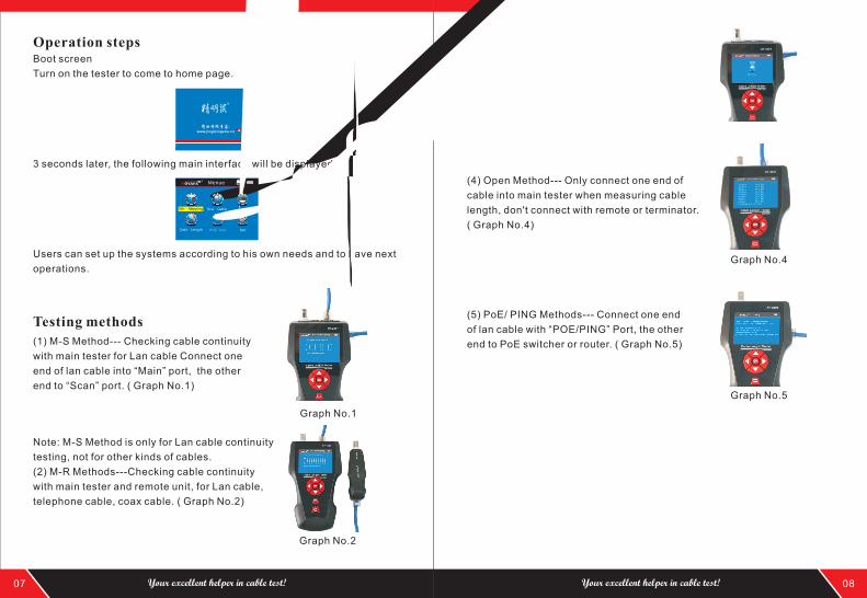
Boot screen
Turn on the tester to come to home page.
Operation steps
3 seconds later, the following main interface will be displayed:
Users can set up the systems according to his own needs and to have next
operations.
(1) M-S Method--- Checking cable continuity
with main tester for Lan cable Connect one
end of lan cable into “Main” port, the other
end to “Scan” port. ( Graph No.1)
Testing methods
Note: M-S Method is only for Lan cable continuity
testing, not for other kinds of cables.
(2) M-R Methods---Checking cable continuity
with main tester and remote unit, for Lan cable,
telephone cable, coax cable. ( Graph No.2)
Note: M-R Methods is for cable continuity
testing, not for cable length measuring.
(3) Scan method---“ RJ45 Scan”“RJ11”“ BNC”
ports are used to trace corresponding cables.
( Graph No.3)
(4) Open Method--- Only connect one end of
cable into main tester when measuring cable
length, don't connect with remote or terminator.
( Graph No.4)
(5) PoE/ PING Methods--- Connect one end
of lan cable with “POE/PING” Port, the other
end to PoE switcher or router. ( Graph No.5)
Wire Mapping Scan Cable
Set
Ping
Menue
POE TestCable Length
Data upload
Start
Wire Mapping
RJ11 BNC
RJ45 CAT6Testing...
Cable open or too short!
1 2 3 4 5 6 7 8 GM:
R: 3 4 5 6 7 8 G
Wire Map:Remote
1 2 3 4 5 6 7 8 GM:
R: 1 2 3 4 5 6 7 8 G
1 2 X 4 5 6 7 8 GM:
S: 1 2 X 4 5 6 7 8 G
p i n 3 :b ro ke n
1 2 3 X X 6 7 8 GM:
R: 1 2 3 X X 6 7 8 G
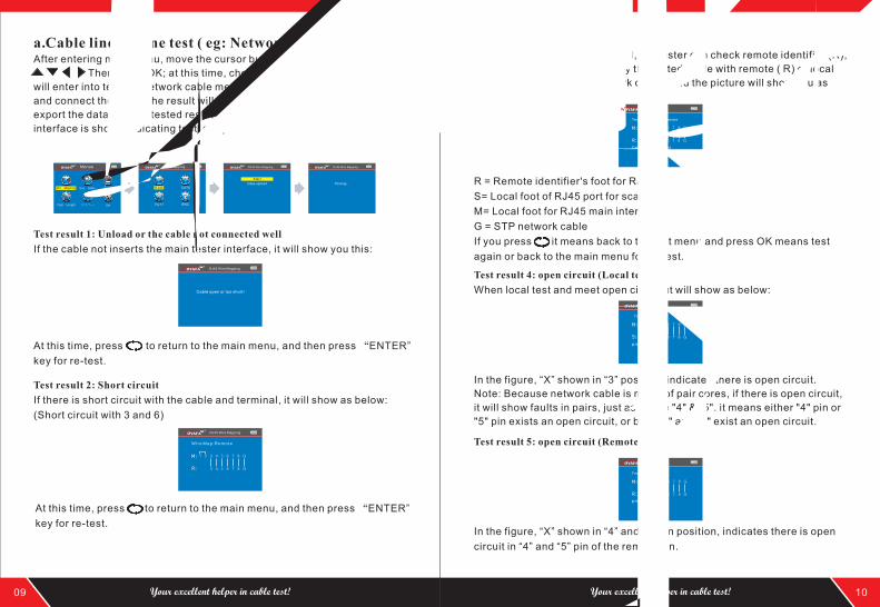
a.Cable line-to-line test ( eg: Network cable):After entering main menu, move the cursor button to cable on-off test.
Then press OK; at this time, choose network cable, press OK, it
will enter into test the network cable menu. And after that, choose START
and connect the RJ45, the result will show you directly; but you also can
export the data and the tested result will into the TF card, the following
interface is shown indicating test is in process:
Test result 1: Unload or the cable not connected well
If the cable not inserts the main tester interface, it will show you this:
At this time, press to return to the main menu, and then press “ENTER”
key for re-test.
Test result 2: Short circuit
If there is short circuit with the cable and terminal, it will show as below:
(Short circuit with 3 and 6)
At this time, press to return to the main menu, and then press “ENTER”
key for re-test.
Test result 3: correct connection
If the device connects corrected, the tester can check remote identifier (R),
or local port (S) cables. If Verify the tested cable with remote ( R) or local
port (S), it can test STP network cable , and the picture will show you as
below :
R = Remote identifier's foot for RJ 45
S= Local foot of RJ45 port for scan
M= Local foot for RJ45 main interface
G = STP network cable
If you press it means back to the last menu and press OK means test
again or back to the main menu for re-test.
Test result 4: open circuit (Local test)
When local test and meet open circuit, it will show as below:
In the figure, “X” shown in “3” position, indicates there is open circuit.
Note: Because network cable is made of pair cores, if there is open circuit,
it will show faults in pairs, just as above "4" &" 5". it means either "4" pin or
"5" pin exists an open circuit, or both "4" and "5" exist an open circuit.
Test result 5: open circuit (Remote test)
In the figure, “X” shown in “4” and “5” pin position, indicates there is open
circuit in “4” and “5” pin of the remote pin.
09 10Your excellent helper in cable test! Your excellent helper in cable test!
Wire Mapping Scan Cable
Set
Ping
Menue
POE TestCable Length
RJ45 Wire Mapping RJ45 Wire Mapping
RJ45 Wire Mapping
RJ45 Wire Mapping
RJ45 Wiremapping
Test mode: Main+Remote
Cable condition: good
Test mode:local
RJ45 Wiremapping
RJ45 Wiremapping
p i n 4 5 :b ro ke n
Test mode:local
Wire Mapping
RJ11 BNC
RJ45 CAT6Wire Mapping Scan Cable
Set
Ping
Menue
POE TestCable Length
1 2 3 X X 6 7 8 GM:
S: 3 X X 6 7 8 G
1 2 3 4 5 6 7 8 GM:
R: 1 2 3 4 5 6 7 8 G
Note: Because network cable is made of pair cores, if there is open circuit,
it will show faults in pairs, just as above "4" &" 5". it means either "4" pin or
"5" pin exists an open circuit, or both "4" and "5" exist an open circuit.
11 12Your excellent helper in cable test! Your excellent helper in cable test!
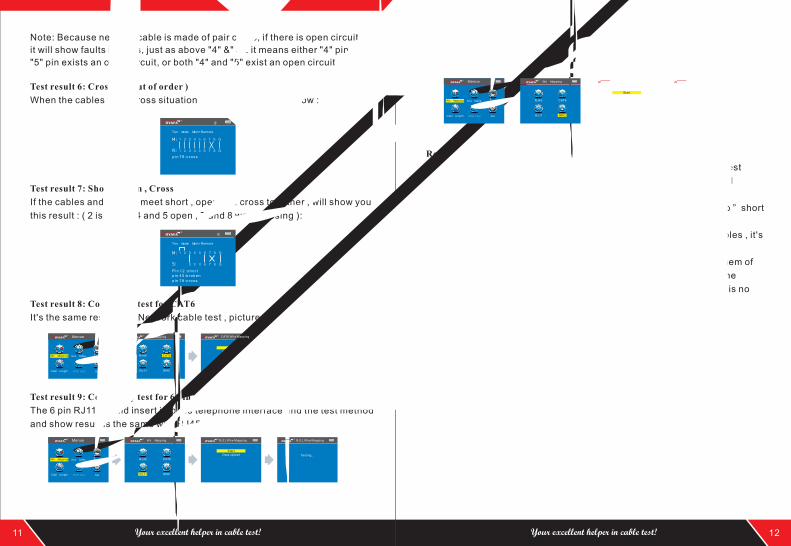
Test result 6: Crossing (out of order )
When the cables have cross situation , it will show you as below :
Test result 7: Short , Open , Cross
If the cables and remote meet short , open and cross together , will show you
this result : ( 2 is short , 4 and 5 open , 7 and 8 was crossing ):
Test result 8: Continuity test for CAT6
It's the same result with Network cable test , picture will show you as below:
Test result 9: Continuity test for 6 pin RJ11
The 6 pin RJ11 should insert into the telephone interface and the test method
and show result is the same with RJ45.
Test result 10: Continuity test for BNC cable
When you test the BNC cable , you should insert into the BNC interface and
the test method is the same with RJ45.
Remote unit with tone when checking wiremap
When use remote unit to check wiremap, users can distinguish the test
result firstly via tones. When the cable is normal, the remote unit will
generate “ beep ” long and slowly.
When the cable is abnormal, the the remote unit will generate “ beep ” short
and quickly.
Attention 1: The line sequence test just for more than 2 pairs of cables , it's
useless for single cable.
Attention 2 : When line sequence test with 1 to 8 , any pin among them of
#7 or #8 for the network cable , any pin among them of #1 or #6 for the
telephone cable or P/4C , 6P/2C , And for BNC cable testing , there is no
any prompt of the remote.
RJ45 Wire Mapping
Test mode: Main+Remote
RJ45 Wire Mapping
Test mode: Main+Remote
Data upload
Start
Testing...
Wire Mapping Scan Cable
Set
Ping
Menue
POE TestCable Length
Wire Mapping
RJ11 BNC
RJ45 CAT6
Data upload
Start
Testing...
CAT6 Wire Mapping CAT6 Wire Mapping
RJ11 Wire Mapping RJ11 Wire Mapping
Wire Mapping Scan Cable
Set
Ping
Menue
POE TestCable Length
Wire Mapping
RJ11 BNC
RJ45 CAT6
Data upload
Start
Testing...
BNC Wire Mapping BNC Wire Mapping
p i n 7 8 : c ro ss
p i n 7 8 : c ro ss
p i n 4 5 :b ro ke nP i n 1 2 : sh o r t
1 2 3 4 5 6 7 8M:
1 2 3 4 5 6 7 8M:
RJ45 Cable Length
Calibration
Unit:Meter
Testing...
Data upload
Load Data
Cable Length
13 14Your excellent helper in cable test! Your excellent helper in cable test!
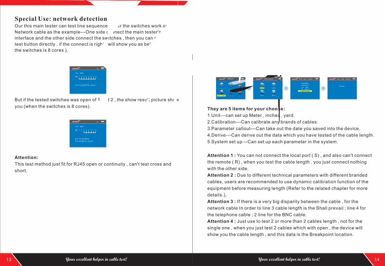
Special Use: network detectionOur this main tester can test line sequence under the switches work on.
Network cable as the example---One side connect the main tester's RJ45
interface and the other side connect the switches , then you can press the
test button directly , if the connect is right , will show you as below ( when
the switches is 8 cores )。
But if the tested switches was open of 1 and 2 , the show result picture show
you (when the switches is 8 cores).
Attention:
This test method just fit for RJ45 open or continuity , can't test cross and
short.
b.Cable length test:( eg: Network cable)After entering main menu, move the cursor button to Cable length
test. Then press OK; at this time, choose network cable, press OK, it will
enter into test the network cable menu. And after that, choose START and
connect the RJ45 port “M” , the other side connect nothing , the result will
show you directly; but you also can export the data and the tested result will
into the TF card, the following interface is shown indicating test is in process:
They are 5 items for your choose:
1.Unit---can set up Meter , inches , yard.
2.Calibration---Can calibrate any brands of cables.
3.Parameter callout---Can take out the date you saved into the device.
4.Derive---Can derive out the data which you have tested of the cable length.
5.System set up---Can set up each parameter in the system.
Attention 1 : You can not connect the local port ( S) , and also can't connect
the remote ( R) , when you test the cable length . you just connect nothing
with the other side.
Attention 2 : Due to different technical parameters with different branded
cables, users are recommended to use dynamic calibration function of the
equipment before measuring length (Refer to the related chapter for more
details.).
Attention 3 : If there is a very big disparity between the cable , for the
network cable In order to line 3 cable length is the Shall prevail ; line 4 for
the telephone cable ; 2 line for the BNC cable.
Attention 4 : Just use to test 2 or more than 2 cables length , not for the
single one , when you just test 2 cables which with open , the device will
show you the cable length , and this data is the Breakpoint location.
Wire Mapping Scan Cable
Set
Ping
Menue
POE TestCable Length
Cable Length
RJ11 BNC
RJ45 CAT6
RJ45 Cable Length
p i n 12 :b ro ke n
P i n 3 4 5 6 7 8 : sh o r t
P i n 12 3 4 5 6 7 8 : sh o r t
RJ45 Wire Mapping
RJ45 Wire Mapping
Test mode:
Test mode:
15 16Your excellent helper in cable test! Your excellent helper in cable test!
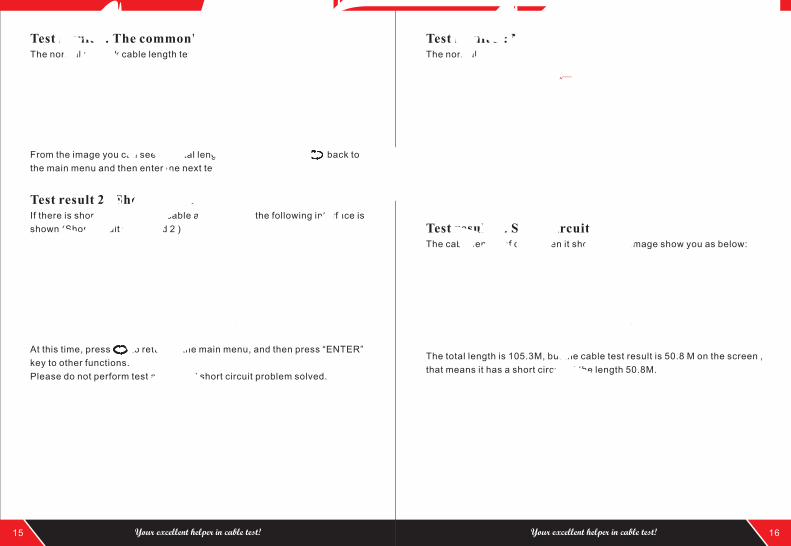
Test result 1: The commonly used Network cableThe normal network cable length test result show you as below:
From the image you can see the total length is 105.3 M, press back to
the main menu and then enter the next testing.
Test result 2 : Short circuitIf there is short circuit with the cable and terminal, the following interface is
shown (Short circuit with 1 and 2 )
At this time, press to return to the main menu, and then press “ENTER”
key to other functions.
Please do not perform test again until short circuit problem solved.
Test result 3 : Normal CAT6The normal cat 6 cable length test result show you as below:
At this time, press to return to the main menu, and then press “ENTER”
key to other functions.
Please do not perform test again until short circuit problem solved.
Test result 4 : Short circuit of cat 6The cable length of cat 6 when it short circuit, image show you as below:
The total length is 105.3M, but the cable test result is 50.8 M on the screen ,
that means it has a short circuit at the length 50.8M.
RJ45 Cable Length
RJ45 Cable Length
1 Open 105.3m2 Open 105.3m3 Open 105.3m4 Open 105.3m5 Open 105.3m6 Open 105.3m7 Open 105.3m8 Open 105.3mTotal length:105.3m
1 Open 50.8m2 Open 50.8m3 Open 105.3m4 Open 105.3m5 Open 105.3m6 Open 105.3m7 Open 105.3m8 Open 105.3mshorten location for Pin 12:50.8mTotal length:105.3m
1 Open 105.3m2 Open 105.3m3 Open 105.3m4 Open 105.3m5 Open 105.3m6 Open 105.3m7 Open 105.3m8 Open 105.3mTotal length:105.3m
CAT6 Cable Length
CAT6 Cable Length
1 Open 50.8m2 Open 50.8m3 Open 105.3m4 Open 105.3m5 Open 105.3m6 Open 105.3m7 Open 105.3m8 Open 105.3mshorten location for Pin 12:50.8mTotal length:105.3m
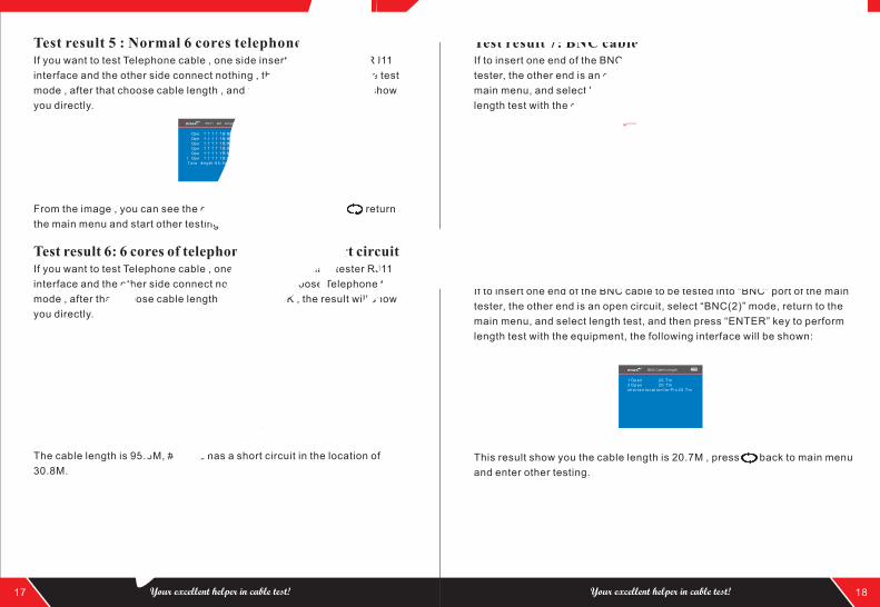
Test result 5 : Normal 6 cores telephone cableIf you want to test Telephone cable , one side insert the main tester RJ11
interface and the other side connect nothing , then choose Telephone test
mode , after that choose cable length , and press OK , the result will show
you directly.
From the image , you can see the cable length is 95.6M , press return
the main menu and start other testing.
Test result 6: 6 cores of telephone cable with short circuitIf you want to test Telephone cable , one side insert the main tester RJ11
interface and the other side connect nothing , then choose Telephone test
mode , after that choose cable length , and press OK , the result will show
you directly.
The cable length is 95.6M, #1 & #2 has a short circuit in the location of
30.8M.
Test result 7: BNC cable length testIf to insert one end of the BNC cable to be tested into “BNC” port of the main
tester, the other end is an open circuit, select “BNC(2)” mode, return to the
main menu, and select length test, and then press “ENTER” key to perform
length test with the equipment, the following interface will be shown:
This result show you the cable length is 60.2M , press back to main menu
and enter other testing.
Test result 8 : BNC cable length test with short circuitIf to insert one end of the BNC cable to be tested into “BNC” port of the main
tester, the other end is an open circuit, select “BNC(2)” mode, return to the
main menu, and select length test, and then press “ENTER” key to perform
length test with the equipment, the following interface will be shown:
This result show you the cable length is 20.7M , press back to main menu
and enter other testing.
17 18Your excellent helper in cable test! Your excellent helper in cable test!
RJ11 Cable Length
1 Open 95.6m2 Open 95.6m3 Open 95.6m4 Open 95.6m5 Open 95.6m6 Open 95.6mTotal length:95.6m
RJ11 Cable Length
1 Open 30.8m2 Open 30.8m3 Open 95.6m4 Open 95.6m5 Open 95.6m6 Open 95.6m7 Open 95.6m8 Open 95.6mshorten location for Pin 30.8mTotal length:95.6m
1 Open 60.2m2 Open 60.2mTotal length:60.2m
BNC Cable Length
1 Ope n 20 .7m2 Ope n 20 .7msh o r t e n l oca t i on f o r P i n 20 .7m
BNC Cable Length
Tseting...
13.3Meter13.7Meter
Calibration 1
Calibration 2
Calibration 3
Calibration 4
Calibration 5
Calibration 6
Calibration 7
Calibration 8
Calibration 9
Return
Saving...
Load!
Data saved to:LONGRJ45.TXT
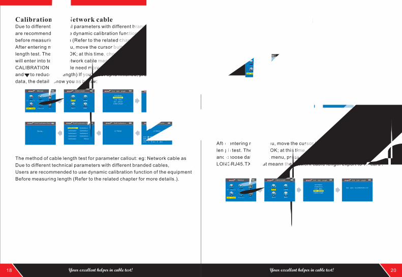
Calibration: eg: Network cableDue to different technical parameters with different branded cables, users
are recommended to use dynamic calibration function of the equipment
before measuring length (Refer to the related chapter for more details).
After entering main menu, move the cursor button to Cable
length test. Then press OK; at this time, choose network cable, press OK, it
will enter into test the network cable menu. And after that, choose
CALIBRATION (this cable need more than 10 M to calibrate, press to add
and to reduce the length) If you're set up is finished, press OK to save the
data, the details show you as below:
The method of cable length test for parameter callout: eg: Network cable as
Due to different technical parameters with different branded cables,
Users are recommended to use dynamic calibration function of the equipment
Before measuring length (Refer to the related chapter for more details.).
After entering main menu, move the cursor button to Cable
length test. Then press OK; at this time, choose network cable, press OK,
and choose parameter callout menu, press OK to choose the data where
you saved. After that press OK, then if the screen will show you Loaded,
that means you have done it.
Data export: eg: Network cable After entering main menu, move the cursor button to Cable
length test. Then press OK; at this time, choose network cable, press OK,
and choose data export menu, press OK and show you “ data saved into
LONGRJ45.TXT “ that means the network cable length export to TF card .
18 20Your excellent helper in cable test! Your excellent helper in cable test!
Wire Mapping Scan Cable
Set
Ping
Menue
POE TestCable Length
Cable Length
RJ11 BNC
RJ45 CAT6
RJ45 Cable Length
Calibration
Unit:Meter
Data upload
Load Data
Cable Length
RJ45 Calibration
RJ45 CalibrationRJ45 CalibrationRJ45 Calibration SaveRJ45 Calibration Save
Wire Mapping Scan Cable
Set
Ping
Menue
POE TestCable Length
Cable Length
RJ11 BNC
RJ45 CAT6
RJ45 Cable Length
Calibration
Unit:Meter
Data upload
Load Data
Cable Length
RJ45 Calibration Load
Calibration 1
Calibration 2
Calibration 3
Calibration 4
Calibration 5
Calibration 6
Calibration 7
Calibration 8
Calibration 9
Return
RJ45 Calibration Load
Wire Mapping Scan Cable
Set
Ping
Menue
POE TestCable Length
Cable Length
RJ11 BNC
RJ45 CAT6
RJ45 Cable Length
Calibration
Unit:Meter
Data upload
Load Data
Cable Length
RJ45 Cable Length
press once,+ 0.1mpress once,-0.1mlong press to set the data quicklypress "ok "to store the data
Scan Cable
Scanning...
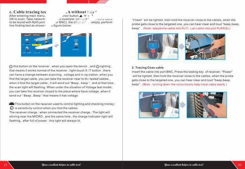
c. Cable tracing test ( NF-8601A without this function)After entering main menu, move the cursor button Then press OK to scan; Take network cable as an example: connect the network cable to be found with Rj45 port (RJ11, or BNC), the other side is empty, perform line finding test as shown in the figure below:
this button on the receiver , when you open the device , and lighting ,
that means it works normal of the receiver , light-touch SET button , there
can have a change between scanning , voltage and in-operation .when you
find the target cable, you can take the receiver near to the tested cables ,
when it find the target cable , it will send out “Beep , beep “ , and at that time ,
the scan light will flashing. When under the situation of Voltage test model,
you can take the receiver closed to the place where have voltage ,when it
send out “ Beep , Beep “ that means it has voltage.
This button on the receiver used to control lighting and checking money;
is sensitivity control when you find the cables.
The receiver charge : when connected the receiver charge , The light will
shining near the MICRO , and the same time , the charge Indicator light will
flashing , after full of power , this light will always lit.
1. Tracing cable (RJ45/RJ11 Cable) which is connected to switch or router.
Insert the cable into port RJ11/ RJ45 (S), Press the testing key of receiver,
“Power” will be lighted, then hold the receiver close to the cables, when the
probe gets close to the targeted one, you can hear clear and loud “beep,beep,
beep” . (Note: telephone cable into RJ11, Lan cable into port RJ45(S) )
2. Tracing Coax cable
Insert the cable into port BNC, Press the testing key of receiver, “Power”
will be lighted, then hold the receiver close to the cables, when the probe
gets close to the targeted one, you can hear clear and loud “beep,beep,
beep” . (Note : turning down the voice slowly help trace cable easily )
21 22Your excellent helper in cable test! Your excellent helper in cable test!
Wire Mapping Scan Cable
Set
Ping
Menue
POE TestCable Length
Connection diagram of crosstalk line pair
12
36
45
78
12
36
45
78
12
34
56
78
12
34
56
78
1 2 3 4 5 6 7 8 GM:
R: 1 2 3 4 5 6 7 8 G
Data upload
Start 12345678
0.0V0.0V0.0V0.0V0.0V0.0V0.0V0.0V
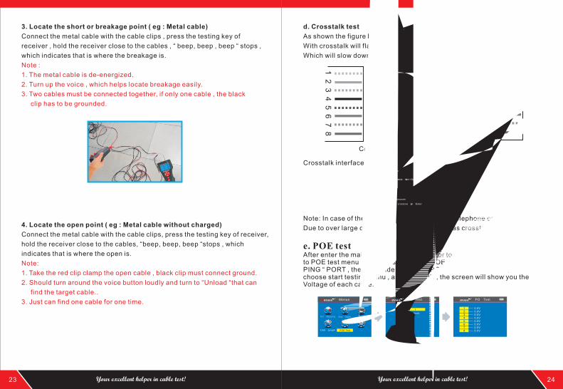
3. Locate the short or breakage point ( eg : Metal cable)
Connect the metal cable with the cable clips , press the testing key of
receiver , hold the receiver close to the cables , “ beep, beep , beep “ stops ,
which indicates that is where the breakage is.
Note :
1. The metal cable is de-energized.
2. Turn up the voice , which helps locate breakage easily.
3. Two cables must be connected together, if only one cable , the black
clip has to be grounded.
4. Locate the open point ( eg : Metal cable without charged)
Connect the metal cable with the cable clips, press the testing key of receiver,
hold the receiver close to the cables, “beep, beep, beep “stops , which
indicates that is where the open is.
Note:
1. Take the red clip clamp the open cable , black clip must connect ground.
2. Should turn around the voice button loudly and turn to “Unload “that can
find the target cable..
3. Just can find one cable for one time.
d. Crosstalk test
As shown the figure below: it shows 3, 6 and 4, 5 with crosstalk. The line pair
With crosstalk will flash to indicate failure. If the testing cable is crosstalk,
Which will slow down the network speed:
Crosstalk interface is shown as below:
Note: In case of the non-twisted-pair cable like telephone cable,
Due to over large crosstalk, it generally shown as crosstalk.
e. POE testAfter enter the main menu , press this cursor to move , and point to POE test menu , and press OK to test POE; Take one side insert the “POE/PING “ PORT , the other side insert into POE Router or Ethernet , then choose start testing menu , and press OK , the screen will show you the Voltage of each cable.
23 24Your excellent helper in cable test! Your excellent helper in cable test!
RJ45 Wire Mapping
Test mode: Main+Remote
Wire Mapping Scan Cable
Set
Ping
Menue
POE TestCable Length
POE Test
3 4 5 6 crossover
crossover pins flicker
POE Test
Data upload
Start
POE Test
Wire Mapping Scan Cable
Set
Ping
Menue
POE TestCable Length
Data saved to:POE.TXT
Data upload
Start
Ping
ConfigurePing
Ping Ping
Ping
Data saved to:PING.TXT
Destination IP: 192.168.1.1
Local IP: 192.168.1.110
Default Router: 192.168.1.1
Subnet Mask: 255.255.255.0
Return
Set
Language:English
Light: Level 3
Light time: 15s
Auto OFF: OFF
Systerm theme: Blue
Systerm information
Return
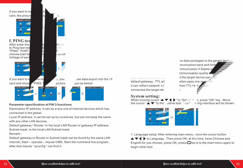
If you want to save the tested result, you can choose data export into the TF
card, the picture show you as below:
f. PING test:After enter the main menu , press this cursor to move , and point to Ping test menu , and press OK to test Ping; Take one side insert the “PING “ PORT , the other side insert into POE Router or Ethernet , then choose start testing menu , and press OK , the screen will show you the Voltage of each cable.
If you want to save the tested result, you can choose data export into the TF
card and choose “PING.TXT”, the picture show you as below:
Parameter specification of PING functions
Destination IP address: It can be every one of Internet devices which has
connected in the global.
Local IP address: It can be set up by ourselves, but can not keep the same
with any other LAN devices.
Default gateway / Router: In the local LAN Router or gateway IP address.
Subnet mask: In the local LAN Subnet mask
Remark :
Default gateway or Router or Subnet mask can be found by the same LAN
internet; Start – operate – impute CMD, Start the command line program ,
after that impute “ ipconfig “ can find it.
Usage :
1.LAN communication device
Destination IP address was set to any one of computer in the same LAN , it
can test the LAN whether is normal between mainframes.
2.Network communication test
Destination IP address was set to any one of external network , such as
180.97.33.108, it can test the LAN whether is normal between mainframes.
Instructions of the test result:
The host tester will send four 32 bytes data packages to the garget device ;
The time means the host tester Communication back and forth between the
target device, that can judge the Communication if Stable and reliable.
When it shows 1ms, it means the Communication quality is great. TTL : the
quantity between the host tester and the target device passed router or
default gateway , TTL will reduce 1 when pass one router or default gateway ,
it can reflect network' s topology . When TTL=4, it means the host tester
connected the target device directly.
System setting:When moving cursor “ to “Setup” item, press “OK” key . Move the cursor “ ”to the relative test . The following interface will be shown:
”
1. Language setup: After entering main menu, move the cursor button
to Language . Then press OK; at this time, have Chinese and
English for you choose, press OK, press back to the main menu again to
begin other test.
25 26Your excellent helper in cable test! Your excellent helper in cable test!
POE Test
Wire Mapping Scan Cable
Set
Ping
Menue
POE TestCable Length
Wire Mapping Scan Cable
Set
Ping
Menue
POE TestCable Length
Ping
ConfigurePing
Data upload
Start
Ping
Wire Mapping Scan Cable
Set
Ping
Menue
POE TestCable Length
Ping
ConfigurePing
Configure
Wire Mapping Scan Cable
Set
Ping
Menue
POE TestCable Length
PING 192.168.1.1 32 bytes of datasreply from 192.168.1.1 :time=1ms TTL=64
192.168.1.1 PING data infodigit packet:sent=4 received=4 loss=0round trip time (unit:ms)shortest time=1ms longest=1ms average=1ms

Thank you for using noyafa’s product
welcome to use next time
bye!
2. Backlight brightness: After entering main menu, move the cursor button
to backlight brightness.Then press OK;at this time,3 kinds them
for you choose, press OK, press back to the main menu again to begin
other test.
3. Backlight time : After entering main menu, move the cursor button
to backlight time . Then press OK; at this time, 15s,30s,1min for
you choose, press OK, press back to the main menu again to begin other
test.
4. Auto power-off : After entering main menu, move the cursor button
to Auto power-off . Then press OK; at this time, 5 kinds of them
for you choose, press OK, press back to the main menu again to begin
other test.
5. System theme: After entering main menu, move the cursor button
to System theme . Then press OK; at this time, 3 kinds of them
for you choose, press OK, press back to the main menu again to begin
other test.
6. Export data : After entering main menu, move the cursor button
to Export data . Then press OK; at this time, you can export all of the data
which you saved into the TF card that makes you can check them more
convenient on computer. (When you export the data , you just insert the TF
card , when you do this step ok , it will show you a battery symbol on the left
)
Shutdown
When you finished all the operation, please remember shut down the device
to keep it.
27 28Your excellent helper in cable test! Your excellent helper in cable test!
NF-701 NF-905 NF-906A
NF-806B
NF-468L NF-300 NF-HDMI
NF-838 NF-816
NF-868 NF-268 NF-8601