iDesign Software Version 1.10 16.01.2015 Software Version > 2.0 … · 2019-05-17 · Version 1.10...
229
Software Manual iDesign Software Version 1.10 16.01.2015 Software Version > 2.0.6 Article no. of the documentation: 71800113 Read these instructions before starting any work!
Transcript of iDesign Software Version 1.10 16.01.2015 Software Version > 2.0 … · 2019-05-17 · Version 1.10...

Software Manual
iDesign Software
Version 1.10 16.01.2015
Software Version > 2.0.6 Article no. of the documentation: 71800113
Read these instructions before starting any work!

Version 1.10 Software iDesign Version > 2.0.6
iDesign
Page 2 of 229
Status Date Section Reason for change
1.00 24.08.09 All First issue
1.01 10.11.09 All Text formatting and system server combined, data base connection, advanced user management
1.02 10.10.10 All USB update function
1.03 17.02.11 All
3
7
8.2
9.8
10.1
Index
Figure update
Add chapter „Software design“
Add submenu
Add reset settings, date/time, save settings, load settings
Add chapter „Terminal“
Displace ML device in chapter connection 9
Add chapter log files
Delete index
1.04 29.08.11 5.3 Update status window
Add DPI-Calculator
Update date/time
Add shift code
Add USB Stick Backup
Add automatic firmware update
Add iDesign configuration
Add Terminal connection
1.05 08.03.12 Status
PopUp menu of the system symbols
Add system information and system configuration
Change name
Change IP address
Change X1JET configuration
Save label
USB firmware update
Save connection
Figures complete renewed
1.06 22.03.13 User management
Status window
Main menu - redesign
Parameter window
Search automatically MOP devices in network
1.07 24.07.13 User management on the systems

Version 1.10 Software iDesign Version > 2.0.6
iDesign
Page 3 of 229
© Weber Marking Systems GmbH
Maarweg 33
D-53619 Rheinbreitbach
Tel.: +49 (0) 2224 7708-0
Fax: +49 (0) 2224 7708-20
E-Mail: [email protected]
Internet: www.webermarking.de
NOTE!
Weber Marking Systems GmbH has made every effort to
ensure the completeness, topicality and correctness of the
information in this manual. Errors in the documentation can
nevertheless not be excluded; Weber Marking Systems
GmbH therefore excludes any warranty claims based on this
information. Changes to the information contained in this
documentation are reserved and may be made without
notification at any time.
This documentation or parts thereof may only be copied,
photocopied, duplicated or translated into other languages
for own requirement. Reproduction for handout to third
parties is not permitted without prior written consent by
Weber Marking Systems GmbH.

Version 1.10 Software iDesign Version > 2.0.6
iDesign
Page 4 of 229
Table of Contents
General .................................................................... 9
Information on this operating manual 9
Explanation of symbols 10
Limitation of liability 11
Copyright 11
Guarantee terms 11
Customer service 11
Intended use 12
Installation and set-up ........................................... 13
System requirements 13
Install software 13
Starting and ending software 17
Software design ..................................................... 20
Home page 20
Navigation menu 20
Information dialogue 21
System tool bar 21
Status LED 23
Connection information 23
PopUp – menu of the system symbol 24
Functions ................................................................ 25
Description of functions 25
Submenu status 25
Submenu Printing 35
Submenu Label backup 37
Submenu Settings 39
Tab Print parameter 39
Print delay 40
Speed 40
Intensity 41
Zoom 42
Print direction 42
Nozzle row 43
Upside down 44
Encoder resolution 44
Repeat distance / Print repeat number 46
Reverse print delay 46
Print start delay bi-directional 47
Tab Print head setup 47

Version 1.10 Software iDesign Version > 2.0.64
iDesign
Page 5 of 229
Store variable fields 49
Tab Spitting and Warming 49
Tab Calibration 51
Tab Input configuration 51
System settings ..................................................... 52
Tab System Setup 58
Language 58
Store variable fields 58
Store parameter into label 58
Barcode correction 59
Datamatrix pixel reduction 59
Turn display 59
Print technology 59
NonStopPrinting 60
HiSpeed 61
Head configuration 61
System configuration 62
Device name 62
Cofiguration code 63
Firmware Update 63
iJET / X-Serie USB Update (offline) 64
iJET / X-Serie online Update 64
CompactLine / MaxiLine / MultiLine MX – Update 66
Xilings – Update 66
Firmware- and Xilings-versions overview 67
Change IP-address 68
Netmask 68
Gateway 68
Stitch device 69
Tab Input Output Configuration 73
Tab Serial Interface EIA232 74
Tab Special settings 75
Terminal 76
DB Print ................................................................... 79
General description 79
Creating a print job 79
Label creation 80
Allocation of Label 80
Setup 81
Start - Stop print job 81
Editor – Label design ............................................ 83

Version 1.10 Software iDesign Version > 2.0.6
iDesign
Page 6 of 229
Description of functions 83
Create print image ................................................. 87
Insert a text field 87
Insert a date field 90
Insert a counter field 94
Insert a barcode/ 2D Code 97
Insert a variable field 100
Insert a logo 101
Insert an action field 104
Reference fields 111
Store parameter into label – Embedded parameters 112
Save print image 113
Open print image 114
Ink consumption calculator 114
Label groups 115
Database 117
USB Stick Backup 120
Label from database 122
Connections ........................................................... 123
Add system 123
Search at com ports 123
Search in network 124
Save connection 124
Delete connection 125
Update firmware 125
iDesign system server 125
Stop server 126
Start server 126
Interface logging 126
Virtual systems on a USB-Stick 128
Tools ........................................................................ 129
General settings 129
Terminal 133
USB Firmware Update 136
User Management 139
Event Logging 164
Font Creator 164
Signal Analysis 169
iDesign Touch structure ........................................ 170
Main menu 170
Status displays / Signal lamps 171

Version 1.10 Software iDesign Version > 2.0.64
iDesign
Page 7 of 229
System functions 171
iDesign Touch functions 172
Toogle functions 172
Call up the screen keyboard 172
Arrow keys 173
System functions ................................................... 174
Load print image 174
Display print storage 175
Menu Settings 176
Submenu print heads 176
Tab Print parameter 177
Print delay 177
Speed in m/min / Intensity / Zoom 178
Print direction 179
Nozzle row 180
Upside Down 181
Repeat distance / Print repeat number 181
Reverse print delay 182
Print start delay bi-directional 182
Tab Print head setup 183
Tab Spitting and Warming 184
Tab Calibration 185
Tab Input configuration 187
Submenu System 188
Tab Device Setup 188
Set default 189
Save set of parameter 189
Language 190
Store variable fields 190
Store parameter into label 191
Barcode correction in pixel 191
Head configuration 191
Master head configuration 193
Print technology 193
NonStopPrinting 193
HiSpeed 193
Device name 194
Configuration code 194
Update firmware 194
IP Address 194
Netmask 194
Gateway 194

Version 1.10 Software iDesign Version > 2.0.6
iDesign
Page 8 of 229
Tab Input Output Configuration 195
Tab Serial interface EIA232 196
Tab Special settings 197
Submenu Logging 198
Menu Status 199
iDesign Touch functions ....................................... 200
Menu Editor 200
Create print image 202
Insert a text field 203
Insert a date field 205
Insert a barcode 206
Insert a counter field 208
Insert a variable field 209
Insert a graphic 210
Assign a set of parameters to a print image 211
Data base 212
Edit the font format 213
Save print image 214
Open print image 214
Delete print image 216
Menu Setup 216
Submenu System 216
Specify start parameter 217
Adjust Event log 218
User language 218
Counter start value 219
Check for firmware update 220
Print pause after Shutdown 220
Disable main window frame 220
Keyboard layout 220
Store variable fields 220
User Management 220
Submenu Interface 221
Submenu Data base 223
Select data base 223
Search 225
Settings 225
Submenu Directories 226
Menu Action log 227
Appendix ................................................................. 228
Directory structure 228
Own notes 229

Version 1.109 Software iDesign Version > 2.0.64
iDesign
Page 9 of 229
General
Information on this operating manual
This manual enables safe and effective use of the software.
The manual is a component of the software.
The manual must be available to the staff at all times near the PC
on which the software is installed.
The staff working with the software must have studied this manual
and be familiar with the content.
Compliance with all safety notes and instructions given in this
manual is a basic prerequisite for safe and efficient working.
Illustrations in this manual serve to provide a basic understanding
and may differ at times.

Version 1.1010 Software iDesign Version > 2.0.66
iDesign
Page 10 of 229
Explanation of symbols
Safety notes Safety notes are identified by symbols in this manual. The safety
notes are preceded by mnemonics signifying the severity of the
hazard.
It is imperative to observe the safety notes and to act with care to
avoid material damage.
CAUTION!
… points out a possibly dangerous situation which
may lead to material damage if not heeded.
Tipps and recommendations
NOTE!
… points out useful tips and recommendations as
well as information to ensure effective and trouble-
free operation..
Result
… this symbol points out a result, following an
action by the operator.

Version 1.109 Software iDesign Version > 2.0.64
iDesign
Page 11 of 229
Limitation of liability
All the information and instructions in this manual were compiled
based on the current standards and regulations, state of the art
technology and our many years of know-how and experience.
The manufacturer is not liable for damages resulting from:
disregarding the manual
improper use
use of untrained staff
changes to the software
The obligations agreed upon in the supply agreement, the general
terms and conditions, the manufacturer’s delivery terms and the
statutory provisions applicable at the time of conclusion of the
contract are applicable.
We reserve the right to make technical changes to improve the
performance and in the course of on-going development.
Copyright
This manual is copyright protected and intended for internal use
only.
Making the manual available to third parties, any form of
duplication – fully or in part – as well as utilization and/or disclosure
of the content, except for internal use, is not permitted without the
written consent of the manufacturer.
Offenders will be liable for damages. Rights to further claims are
reserved.
Guarantee terms
The guarantee terms are specified in the General terms and
conditions of the manufacturer.
Customer service
Please refer to our customer service for technical information.
Refer to Page 3 for contact details.
Our staff is furthermore always interested in new information and
experiences arising from the use of the product and which may be
valuable information for product improvement.

Version 1.1010 Software iDesign Version > 2.0.66
iDesign
Page 12 of 229
Intended use
The software has been designed and implemented exclusively for
the intended use described herein.
The software serves to develop and administrate print images
which are transferred to a Weber Marking Systems printing
system.
Intended use also includes adherence to all the specifications in
this manual.
Any use beyond the intended use or any other use is regarded as
misuse.
Any claims arising from damages due to misuse will be rejected.

Version 1.109 Software iDesign Version > 2.0.64
iDesign
Page 13 of 229
Installation and set-up
System requirements
To install the iDesign software on a PC, the following minimum
system requirements must be met:
Pentium III processor or later
Windows XP®, Windows Vista,
®, Windows 7
512 MB RAM
25 to 30 MB hard disk
SVGA monitor, 256 colors minimum
PC mouse
or Touchscreen
Printer interface
(either USB, RS 232 , RS 442 or Ethernet)
Install software
The following steps imply that you have an installation file on CD or
USB-stick or that you download the software on the Weber
Marking Partner Portal with the following link:
www.bluhmsysteme.com/download/software/iDesign/Setup_iDesign.exe
Unser this link you’ll find always the latest iDesign software.
You’ll get further information from the Support.
You’ll get the latest software update under the link, specified above
or the info button. The latest software includes also the latest
firmware versions.
1. Change to the index where you saved the actual iDesign
version.
2. Double click the iDesign.exe file.
3. Click on the OK button.

Version 1.1010 Software iDesign Version > 2.0.66
iDesign
Page 14 of 229
Fig. 1 iDesign Setup Assistant
4. Click on the Next > button.
Fig. 2: Select destination folder
5. Click on Change… button if required and select destination
folder.
(default path: C:\Programs\iDesign \)
6. Click on the Next > button.

Version 1.109 Software iDesign Version > 2.0.64
iDesign
Page 15 of 229
Fig. 3: Start installation
Fig. 4: Complete installation
7. Click on Finish button.

Version 1.1010 Software iDesign Version > 2.0.66
iDesign
Page 16 of 229
Fig. 5: Extract the Windows Driver
8. Finally extract the Windows Driver and start the installation.

Version 1.109 Software iDesign Version > 2.0.64
iDesign
Page 17 of 229
Starting and ending software
Start iDesign
1. To start iDesign,
– Click on the desktop button
or:
– Click the iDesign button in the Start/Programs/iDesign
Windows menu bar.
The Start window opens.
HINWEIS!
Die Drucksysteme werden nur angezeigt, wenn
diese vorher angemeldet wurden.
Fig. 6: Start window
NOTE!
The print systems are shown only if they are
registered previously.

Version 1.1010 Software iDesign Version > 2.0.66
iDesign
Page 18 of 229
2. Alternatively, iDesign Touch can be start optimized for a
Touch surface,
– click on the icon on the desktop.
or:
– click the button iDesign Touch in the Windows menu bar
Start/Program/iDesign/.
The start window opens.
Fig.
7: Start window
NOTE!
The print systems are shown only if they are
registered previously.

Version 1.109 Software iDesign Version > 2.0.64
iDesign
Page 19 of 229
End iDesign
1. To end iDesign,
– Click the button in the title bar.
Fig. 8: End iDesign
The Start window closes
Or
– Click on end on the bottom left.
Fig. 9: End iDesign

Version 1.1010 Software iDesign Version > 2.0.66
iDesign
Page 20 of 229
Software design
Home page
The iDesign software is organized in two fields. On the left is the
navigation menu and on the right is the information part of the
software.
Navigation menu
The navigation menu opens up the functions of iDesign.
Functions
Status messages are shown, print images and parameter are
managed and can be sent to the desired system.
Print image
Functions and settings for the print image. Print images can be created and managed with the editor and can send to one or more systems. Data base connections can be configured and created automatically. Print images can load into the system via the USB stick backup function.
Connections
The connections menu is used to configure connections to the print
systems.
Tools
The tools menu is used to make settings for the logging, user
management, the language of the software and a system-
independent terminal program.
End
To end the iDesign software.

Version 1.109 Software iDesign Version > 2.0.64
iDesign
Page 21 of 229
Information dialogue
Click the button top right to select the information dialogue.
You can find the complete version number and additional notes for
these iDesign version.
Fig. 10: Information dialog
Here you can also download the version for a software update.
System tool bar
Fig. 11: System tool bar
The system tool bar contains information to the already configured
print systems.

Version 1.1010 Software iDesign Version > 2.0.66
iDesign
Page 22 of 229
NOTE!
The system tool bar is visible in main menu items
„Functions“ and „Connections“ only.
Fig. 12: System symbol of the X4Jet
The illustration of the print systems in the tool bar is made with a
picture of the connected system, the name, a status LED and
connection information.
If more systems are registered as they can shown, the systems
can scrolled with the bar at the lower side.
Systems, which are registered but aren’t available, are shown in
grey.
Fig. 13: Not available system
The system can be activated for editing with a click on the icon.
The frame around the icon is then wider than the other icons.

Version 1.109 Software iDesign Version > 2.0.64
iDesign
Page 23 of 229
Status LED
The status LED visualizes information about the operating
condition of the activated system.
NOTE!
The status signals can have different meanings,
depending on the system. For further information
have a look to the operating manual.
Symbol Meaning Description
OK The system is ready for use. It exist no problems.
Warning This report is displayed if i.e. a cartridge is nearly empty
and should be changed.
Alarm The system is in the „Alarm“ status and is not ready for
print.
No connection No connection to the system.
NOTE!
System symbol blinks grey
If more than one PC access the print system (or
more than two different PC’s access the iJET or
X4JET), the system flashes grey.
In this case is no configuration of the system over
iDesign possible.
Connection information
Depending on the type of connection the status displays two
information.
1. The name of the system, if a name has been assigned.
2. Different information, depending on the connection
Connection Meaning
TCP/IP Displays the IP-address of the system
USB cable Displays the chip identification
EIA 232
USB-stick
Displays the used COM-Ports
Displays the serial number

Version 1.1010 Software iDesign Version > 2.0.66
iDesign
Page 24 of 229
PopUp – menu of the system symbol
If you click on a system symbol with the right mouse button, you
get the possibility to change diverse settings of the selected
system.
Fig. 14: PopUp menu of a X1JET XR with USB-stick connection
The settings include:
Menu item Available Description See also
Save all systems Specify an individual name
for the system, e.g.
production line 3
Change IP
address
all systems Change the IP address of the
connected system and in
iDesign.
Chapter: „Change IP“
Add TCP/IP
connection
Always Add a new system in iDesign Chapter: „Add system“
Search system
on the Com
Port
Always Checks the available COM
Ports for connected systems
Chapter: “Search on COM
ports”
Search system
in network
Always Check the actual network for
connected systems
Delete
connection
Always Deletes a system in iDesign Chapter:“Delete connection“
Auto arrange
icons
Always If the check mark is removed,
the system icons can be
placed anywhere on the
screen.

Version 1.109 Software iDesign Version > 2.0.64
iDesign
Page 25 of 229
Functions
Description of functions
The status of the connected systems can be shown.
The functions are used to manage print images and parameters
and to transfer these to available printers.
The connected printers are shown as symbols on the user
interface.
Submenu status
The status menu shows information of the system and whose
operating condition, which can call up.
The window is divided in different fields, depending on the print
system. These fields can be selected via the top tabs.
Status - Panel
The status – panel shows the status of the print system.
Fig. 15: Status screen

Version 1.1010 Software iDesign Version > 2.0.66
iDesign
Page 26 of 229
The status – panel is structured in different fields.
1.) System status
Fig. 16: System status
The system status summarize all status information, it consists of a
status LED, which shows the status of the system and a status list,
which shows the alarm- and error status of the system.
The system has 3 different statuses generally.
a.) Error – The system isn’t ready.
The status LED is red.
b.) Warning – The system isn’t print ready or there is a warning
(ink nearly empty).
The status LED is yellow.
c.) OK – The system is ready and can print.
The status LED is green.
The status list shows the actual error in form of an own status
LED, the print head, which concerns the error information and
a textual information of the error.
Fig. 17: Example of information in the system status
The information is periodically updated and displayed by the
system.
2.) Head status
The head status is displayed below the system status.
This summarizes the information for the print head.

Version 1.109 Software iDesign Version > 2.0.64
iDesign
Page 27 of 229
Fig. 18: Head status and preview
You can find:
a.) Name of the print head
b.) Status LED
summarizes the head status
c.) Filling level of the cartridge in percent
The cartridges and whose filling levels are displayed at the
left edge topdown. The colors of the elements show the
status for the specific cartridges.
d.) Label name
Name of the actual print label.
e.) Print counter
Number of the already printed label.
f.) Preview
Real-time preview of the actual printed label. All fields, also
variable fields, date fields and barcode fields will be
displayed with the actual data.
g.) Head type - pictogram
Shows the print technology with a pictogram.
Cartridges – panel
The cartridges - panel summarizes information for the head and
cartridges.
On the left side is a legend of the displayed information.

Version 1.1010 Software iDesign Version > 2.0.66
iDesign
Page 28 of 229
Fig. 19: Cartridge information
The upper part contains information of the head.
There can be seen:
a.) Name of the print head
b.) Print head technology
Displayed as pictogram and text
c.) Print head configuration
(Single, Twin, Tripple, Quad)
d.) The used channel of the print head
e.) Name of the actual print image
f.) Counter
Number of the previously printed labels
g.) Print status
start, pause, stop
h.) Battery status
Below these information are the cartridge information, for each
cartridge separately side by side.
There can be seen:
a.) Cartridge name
b.) Temperature of the cartridges
c.) Filling level of the cartridges
Graphic and text
d.) Ink status
Graphic (LED) and text

Version 1.109 Software iDesign Version > 2.0.64
iDesign
Page 29 of 229
NOTE!
Not all information are shown for each cartridge-/ print
head type.
Configuration – panel
The configuration-panel summarizes tabular information of the print
system.
Fig. 20: System configuartion
The configuration can saved on a hard disk or can send with
comments via mail.

Version 1.1010 Software iDesign Version > 2.0.66
iDesign
Page 30 of 229
There can be seen:
Name Information Change Available for:
Name System name Yes, see Change name All TCP/IP –
connections
Type System type No All systems
IP-address Shows the actual IP-address of the system,
also when it isn’t connected via TCP/IP
Yes, see Change IP-
address
iJET, X-Serie
Firmware Shows the actual installed firmware version Yes, see Firmware update All systems
Number of heads Shows the number of available heads No All systems
MAC address Shows the actual MAC-address of the
system, also when it isn’t connected via
TCP/IP
No iJET, X-Serie
Configuration Shows the actual set system configuration
(HP, Lexmark, Trident)
Yes, see Change
configuration
X4, X4Plus,
System
configuration
Shows the actual set system configuration
(Basic, Advanced, Pro, Print)
Yes, see Change
configuration
iJET, X-Serie
Serial number Shows the serial number of the system No All systems
Storage capacity Shows the filled storage No Cl2.5, Maxiline,
Multiline
Max. Speed. Shows the maximum print speed of the
system
Yes, see Change
configuration
iJET, X-Serie
Date/Time Shows if the system supports date fields Yes, see Change
configuration
iJET, X-Serie
Variable fields Shows if the system supports variable fields Yes, see Change
configuration
iJET, X-Serie
Barcodes Shows barcode types, which are supported
by the system
Yes, see Change
configuration
iJET, X-Serie
Passwords Shows if the system is password-saved Yes, see Change
configuration
iJET, X-Serie
USB Support Shows if the system supports the USB
interface
Yes, see Change
configuration
iJET, X-Serie
Interface Shows if the system supports the ethernet
interface
Yes, see Change
configuration
iJET, X-Serie
Bluetooth Shows if the system supports the Bluetooth
interface
Yes, see Change
configuration
iJET, X-Serie
Digital IO Shows if the system supports the Digital-IO
interface
Yes, see Change
configuration
iJET, X-Serie
Demo Shows if the system is a demo system Yes, see Change
configuration
iJET, X-Serie
Cartridge-coding Shows if the head coding is active in the
system
No, see Change
configuration
iJET, X-Serie

Version 1.109 Software iDesign Version > 2.0.64
iDesign
Page 31 of 229
None LX Weber
cartridge
Shows if None-Weber cartridges are
activated
No, see Change
configuration
iJET, X-Serie
None HP
SmartCard
cartridge
Shows if cartridges without SmartCard are
activated
No, see Change
configuration
iJET, X-Serie
Maximum print
length
Shows the maximum print length which is
supported by the system
Yes, see Change
configuration
iJET, X-Serie
Save the configuration:
1. Click on „Save“
2. Select the folder to save the file.
3. Enter the file name if necessary.
4. Click on „Save“.
The configuration is saved and can view with every text editor.

Version 1.1010 Software iDesign Version > 2.0.66
iDesign
Page 32 of 229
Inputs/Outputs – panel
The inputs/outputs – panel shows information of the digital in- and
outputs of the system. The field shows diverse graphical real-time
signals. Furthermore there is the possibility for a signal analysis.
Fig. 21: Visualization of the input- and output signals
On the upper field there are control elements to control the display.
These are from left to right:
a.) Start/Stopp of the signal preview
This allows a live preview of the signals, which can be frozen
and clear in the upper picture.
b.) Progress indicator
The signal record and the live preview of the signals takes
place max. 5 minutes.
A green bar in the progress indicator shows how much time
have passed from these 5 minutes.
c.) Record signals
A file dialogue is shown after a click on this icon. Afterwards
the signals will be written as text in a file.
d.) Loupe 1:1
Renew the original size of the live preview.
e.) Loupe +
Zoom in in the live preview.
f.) Loupe –
Zoom out from the live preview again.
g.) Copy to Clipboard

Version 1.109 Software iDesign Version > 2.0.64
iDesign
Page 33 of 229
Copies the current display of the live preview to the Windows
clipboard. This image can than paste into the image
processing software.
h.) Preview in s
The displayed value shows the maximum time interval, which
is shown in the line preview.
i.) Marker 1
Is only available if the signal preview paused. When Marker 1
is selected, you can set a marker (red) with the left mouse
button.
j.) Marker 2
Is only available if the signal preview paused. When Marker 2
is selected, you can set a marker (blue) with the left mouse
button.
k.) Marker difference
Shows the value of the time difference between the blue and
the red marker in seconds.
l.) Display indicated value
The indicated values can also displayed as text.
All signals, which are provided from the system, are listed on the
left side. These signals act as legend of the live preview. The
display of the legend happen by:
a.) Signal name
b.) LED
If the signal is active (High), the LED will be light green. If the
signal is inactive (Low), the LED will be dark green.
c.) Selection-Checkbox
Via the checkbox can determine whether this signal should be
displayed in the live preview. It’s possilble to display up to 10
different signals.
d.) Signal color
The signal color for all signals, which are shown in the live
preview, is assigned automatically.
Following signals are visualized:
a.) Inputs
If the input is active (High), the LED will be light green. If the
input is inactive (Low), the LED will be dark green
b.) Sensor
If the sensor is active (High), the LED will be light green. If the
sensor is inactive (Low), the LED will be dark green
c.) Pulse

Version 1.1010 Software iDesign Version > 2.0.66
iDesign
Page 34 of 229
If the pulse exist (High), the LED will be light green. If the pulse
doesn’t exist (Low), the LED will be red.
d.) Active print
The active print LED of the associated print head will be light
green during a label print, dark green otherwise.
e.) Outputs
The outputs can be set in this field explicitly. By pressing a
respective button the respective output is set ti High for a
second, after that to Low for a second and then back to the
original value, which was present before the button was
pressed.

Version 1.109 Software iDesign Version > 2.0.64
iDesign
Page 35 of 229
Submenu Printing
Fig. 22: iDesign user interface
Print start
To select a print image for print on a specific control system, first
select a control system. Click the “Print” button in the “Functions”
selection field. Select the print image from the list field, bottom
right and select one or more print heads, which should receive the
print image. The selected print heads are marked blue.
To start printing, click the “Start print” button.
If there are variable fields in the print image, they will query now.
If a data base connection is used, a specified data set can be
selected with the search function.
Print stop
Press the „Stop print“ button to stop printing.
Print multiple
Following menu appears to allocate the selected print image to
multiple connected print systems:

Version 1.1010 Software iDesign Version > 2.0.66
iDesign
Page 36 of 229
Fig. 1: Multiple print
Please select the print system and start “Print multiple” with OK.
Stop multiple
Realize a print stop on all selected print systems.

Version 1.109 Software iDesign Version > 2.0.64
iDesign
Page 37 of 229
Submenu Label backup
iDesign sends the created print images from a PC directory via an
interface to the memory of a connected printer.
This enables the printer to print these images even without a
permanent connection to the PC.
Contrary, print images can be transferred from the memory of a
connected printer to the PC, for backup.
iDesign also enables automatic generation and sending of print
images from a database. See also page 122.
1. To send one or more print images from a PC to a print
system,
Click the button in the Symbol bar.
Fig. 23: Backup window

Version 1.1010 Software iDesign Version > 2.0.66
iDesign
Page 38 of 229
Send print images
1. .Select a print image from the list displayed on the left. The
“Change directory” button also enables you to search for
other print images on your hard disk.
2. Click the Send > button or (to send all print images) the Send
all >> button.
Fig. 24: Backup dialog
Receive print images
1. To transfer print images from the printer to a directory, select
the print images from the list displayed on the right.
2. Click the Receive button or (to transfer all print images) the
Receive all button.
Delete print images
1. To delete print images in the printer’s memory, select the print
images in the right field.
2. Click on the button for deletion.
Fig. 25: Delete print images
3. Click Ok. to delete the selected print image in the printer’s
memory.
Or
Click All to delete the selected print image in the printer’s
memory.

Version 1.109 Software iDesign Version > 2.0.64
iDesign
Page 39 of 229
Submenu Settings
Tab Print parameter
The print parameters depend on the connected type of printer.
NOTE!
Consult the printer manual to set the print
parameter.
1. To call up the print parameter, click in the register “Functions”
the “Settings” button.
2. Select the “Print parameters” in the selected print head menu.
Fig. 26: Print parameter
3. Now change the print parameters to configure the selected
system. Any changes are immediately sent to the system.
NOTE!
The minimal and maximum values of the parameter
settings depends on the print system.

Version 1.1010 Software iDesign Version > 2.0.66
iDesign
Page 40 of 229
Print delay
The parameter print delay defines the path distance in mm
between the light barrier trigger by the product and start of printing.
By setting such a print delay, the position of the print image on the
product can be changed. The print delay can be specified for each
print head.
Adjustable values: 0 to 999 mm.
1. Press tab Print head 1 or Print head 2 (depends on the
number of the activated print heads) and select the desired
print head.
2. Click on the tab Print parameter.
3. To set the delay,
– Press arrow keys and set the required delay value.
The value 0 means that printing can be triggered immediately after
the light barrier trigger pulse.
NOTE!
The print start delay must not be greater than the
distance between 2 products. If a print start is
triggered before the last print is finished, it will be
ignored.
Speed
The print speed of the print heads must match the conveyor belt
speed, otherwise print images may be distorted.
There are 2 ways to match the print speed to the conveyor belt
speed:
Internal constant print speed.
External variable print speed via rotary encoder.
If no rotary encoder is connected to the controller, the conveyor
belt speed must be measured or estimated and the determined
value entered as a parameter. A test image (SpeedTest.00I) can
then be used for fine-tuning the print speed. The set print speed is
applicable for the selected print head group.
For single heads head 1 and 2 have the same setting and can’t set
separately.
The following parameters must be entered:
Print speed
Print speed = Conveyor belt speed. The conveyor belt speed must
remain constant!

Version 1.109 Software iDesign Version > 2.0.64
iDesign
Page 41 of 229
Intensity
Print image contrast. If necessary, this parameter may have to be
changed to optimise the print image to the product surface. Higher
intensity means increased density and slower drying of the ink.
1. Press tab Print head 1 or Print head 2 (depends on the
number of the activated print heads) and select the desired
print head.
2. Click on the tab Print parameter.
3. To set the resolution,
– Press arrow keys and set the required delay value.

Version 1.1010 Software iDesign Version > 2.0.66
iDesign
Page 42 of 229
Zoom
This parameter enables an increase or decrease of the number of
pixels. This renders the print image wider or narrower.
1. Press tab Print head 1 or Print head 2 (depends on the
number of the activated print heads) and select the desired
print head.
2. Click on the tab Print parameter.
3. To set the zoom,
– Press arrow keys and set the required delay value.
NOTE!
When printing barcodes, ensure that widening or
narrowing occurs only in the correct ratio. Note the
optimal print intensity of 300 dpi. Observe the
following table!
Barcode width Permitted zoom factor [%]
1 100, 200
2 50, 100, 150, 200
3 66, 100, 133, 166, 200
4 50, 75, 100, 125, 150, 175, 200
5 60, 80, 100, 120, 140, 160, 180, 200
6 50, 66, 83, 100, 116, 133, 150, 166, 183, ...
Print direction
The Print direction parameter specifies the direction in which the
product moves on the conveyor belt as viewed from the print head
side.
1. Press tab Print head 1 or Print head 2 (depends on the
number of the activated print heads) and select the desired
print head.
2. Click on the tab Print parameter.
3. Set the direction of the conveyor belt in the dropdown menu
print direction.

Version 1.109 Software iDesign Version > 2.0.64
iDesign
Page 43 of 229
Nozzle row
Each ink cartridge has two nozzle rows (A and B). One nozzle row
has 150 nozzles.
The nozzles in row A print the uneven numbers 1, 3, 5, 7 …
The nozzles in nozzle row B print the even numbers 2, 4, 6, 8…
Per nozzle row A ~ B, 300dpi are printed vertical.
In this mode, the nozzles are uniformly stressed and the speed
setting is not as critical as with A + B.
If, for instance, using A ~ B, every second print image is of poor
quality, nozzle row A or nozzle row B can be activated.
Both nozzle rows print simultaneously with the setting A+B. The
vertical resolution is 600 dpi. The print image is dark equal. The
speed must be exactly right, because this will cause a shadow or
blurred print when the nozzle rows are not print about each other
correctly.
The nottle rows can set as follows:
Nozzle row Description
A ~ B Printing with both nozzle rows, alternating.
The first print image is printed with nozzle row A
and the second text with nozzle row B.
A + B Printing with both nozzle rows together.
Vertical resolution: 600 dpi
A Printing only with nozzle row A.
Vertical resolution: 300 dpi
B Printing only with nozzle row B.
Vertical resolution: 300 dpi
NOTE!
With setting A + B, the print speed must be accurately
set, to produce a good print result. Otherwise the print
image is blurred (shadow print).

Version 1.1010 Software iDesign Version > 2.0.66
iDesign
Page 44 of 229
To select the Nozzle row,
1. Press tab Print head 1 or Print head 2 (depends on the
number of the activated print heads) and select the desired
print head.
2. Click on the tab Print parameter.
3. Set the desired nozzle row setting in the dropdown menu.
Upside down
The setting Upside Down causes the print image to be printed
upside down.
To select upside down,
1. Press tab Print head 1 or Print head 2 (depends on the
number of the activated print heads) and select the desired
print head.
2. Click on the tab Print parameter.
3. Activate upside down in the dropdown-menu.
Encoder resolution
The encoder resolution is a pilot tool to identify the correct encoder
resolution in the print parameter menu.
The encoder resolution is called up with the additional button.
Fig. 27: DPI-calculator
To calculate the encoder resolution:

Version 1.109 Software iDesign Version > 2.0.64
iDesign
Page 45 of 229
1. First determine the number of pulses, generated by the
encoder for a complete rotation and set the value in the field
„Encoder pulses per rotation“.
2. If the encoder runs direct on the conveyor with a wheel,
select the corresponding checkbox.
Depending on your selection the other needed fields will be
activated.
If the encoder wheel runs direct on the conveyor:
3. Determine the diameter of the friction wheel and enter the
value in the corresponding field.
If the encoder isn’t installed on the conveyor directly:
4. Determine the distance of the conveyor per rotation of the
wheel and enter the value in the corresponding field.
5. If you have done all settings, you can see the value below
“Calculation dpi Shaft Encoder“.
6. Click on „Apply“ to adopt the value in the print parameter
menu as effective resolution and close the DPI-calculator.
7. A fine tuning of the DPI number is necessary for an optimal
print result.

Version 1.1010 Software iDesign Version > 2.0.66
iDesign
Page 46 of 229
Repeat distance / Print repeat number
To print several print images on one product, the number of print
images and the distance between them must be specified.
The distance between print images is measured from print start to
print start.
If you select „5“ the print image will be printed 6 times. 1 print plus
5 repeats.
998 prints 999 print images.
Endless printing can be activated with print repeat of „999“.
Parameter Min. Max. Unit
Distance between print images 0 9999 mm
Number of print images 0 999 -
To enter the repeat distance and the print repeat number,
– Press arrow keys and set the required delay value.
– Endless printing can be activated with a click on the
button at the print repeat number. The value
goes to 999 automatically.
Reverse print delay
Is the print direction backward, i.e. the product moves on the print
head from left to right, the calculation point for the print start delay
can set to right or left edge of the print image.
The setting „left border“ ensures a consistent left alignment.
It should be noted that the width of the print image needs to be part
of the set value.
To select Reverse print delay,
1. Press tab Print head 1 or Print head 2 (depends on the
number of the activated print heads) and select the desired
print head.
2. Click on the tab Print parameter.
3. Select “left border” or “right border” in the dropdown menu
Reverse print delay.

Version 1.109 Software iDesign Version > 2.0.64
iDesign
Page 47 of 229
Print start delay bi-directional
If the setting „print direction“ will be used at the input signal, the
print start delay applies for the opposite print direction.
Therefore the print is positioned exactly by using the print direction
reversal.
The parameter „Reverse print delay“ should set to „left border“.
NOTE!
These parameter is only visible if one input is set to
„print direction“.
To select Print start delay bi-directional,
1. Press tab Print head 1 or Print head 2 (depends on the
number of the activated print heads) and select the desired
print head.
2. Set one input signal to „print direction“ in the tab Input
configuration.
The parameter „print start delay bi-directional“ is shown
in the tab Print parameter.
3. Press arrow keys and set the required value.
Tab Print head setup
The print head setup depend on the connected print technology
and adopt automatically.
NOTE!
Please read the operator manual of the print
system to set the print parameter.
1. Click on the print parameters tab to select them.

Version 1.1010 Software iDesign Version > 2.0.66
iDesign
Page 48 of 229
Fig. 28: Print head setup
2. Change the print head setups to configure the desired system.
All changes will be send to the system immediately.
NOTE!
The head voltage and fire time will be set
automatically, depends on the ink type.
The values should be change carefully and after
instruction, otherwise the cartridge can be
damaged.

Version 1.109 Software iDesign Version > 2.0.64
iDesign
Page 49 of 229
Store variable fields
This option specifies whether a queried variable field is saved with
print request and will be displayed as default line with a new print
request. This is useful to enter only the data that has actually
changed. Data that hasn’t changes can confirm by the Enter-
button.
To save variable fields,
1. Select in the submenu System the tab Device Setup.
2. Set the desired option in the dropdown menu “Store variable
fields”.
Tab Spitting and Warming
The Spitting and Warming adjustments depending on the
connected print technology. e.g. for Trident (MX) is this not
available.
NOTE!
Please read the operator manual of the print
system to set the print parameter.
1. Click on the Spitting and Warming button in the head menu to
select the spitting and warming settings.

Version 1.1010 Software iDesign Version > 2.0.66
iDesign
Page 50 of 229
Fig. 29: Spitting and Warming
2. Now change the Spitting and Warming settings to configure
the selected device. Any changes are immediately sent to the
system.

Version 1.109 Software iDesign Version > 2.0.64
iDesign
Page 51 of 229
Tab Calibration
If a twin print head or a print head with several modules (Triple,
Quad, ...) is connected to the controller, the offset between the two
print heads must be adjusted, if necessary. If single print heads are
connected, a calibration isn’t necessary.
NOTE!
Before the print heads are calibrated, the print speed
or the rotary encoder setting must be correct.
The offset between the two print heads is compensated for by the
input of correction factors.
A negative value means that the print image of this cartridge
moves to the left side and reverse.
The print head must be installed horizontal. There must be neither
an overlap nor a gap between the cartridges in the vertical. Test it
with a print image over all heads.
The speed must be set optimum. The nozzles must be in one row
by printing with A+B. This can be controlled with a loupe. There
must be no shadow print be present.
The intensity must be set optimal by a printing with shaft encoder.
To enter the calibration value,
– Press arrow keys and set the required value.
Tab Input configuration
The inputs of the print system can configured optional and
customer-specific.
It can select between:
Print direction
Upside down
Print pause
Label selection
Bulk System
Shutter Print Head
Reset ink level.

Version 1.1010 Software iDesign Version > 2.0.66
iDesign
Page 52 of 229
System settings
In the menu „System“ are all system specific adjustments for
changing available.
WARNING!
These settings should change from an expert only!
The function of the system can be disrupted by an
incorrect setting.
NOTE!
Every adjustment will be send immediately to the
connected printer.
The elements of the parameter section can be different depending
on the type of system which is connected.

Version 1.109 Software iDesign Version > 2.0.64
iDesign
Page 53 of 229
Fig. 30: System settings
Save to file
The print head- and system settings can saved on a PC. These
can be used for a later system recovery or be linked to a print
image to change system settings depends on the print image.
1. Press the Save button to save the settings.
2. Enter the file name in the dialog field.
3. Concluding click on the Save button
The settings are saved below your selected file name
Open from file
1. Click on the Open button to load an existing configuration.
2. Select the desired configuration file in the dialog field and
confirm with Open.
3. Concluding click on the Send button to send the loaded
configuration to the system.

Version 1.1010 Software iDesign Version > 2.0.66
iDesign
Page 54 of 229
The saved settings can be linked with a print image. See Editor
“connect with set of parameters“.
Load defaults
1. Press Standard value to reset all settings in the delivery
status. Head configuration, ink type and interface values won’t
be changed.
2. Confirm the dialog field with OK
Send fonts and logos
To enable the printer to correctly interpret and display the texts and
graphics used in the print images, the respective fonts and logos
must be transferred to the printer’s memory.
NOTE!
Selection of the fonts and logos depends on the
connected printer.
Standard the required fonts and logos for printing will be sent to the
system automatically when a print image with fonts and logos will
be create in the iDesign editor.
There is the possibility to send the files manually.
Send fonts 1. To send a font to the selected printer, select the “System
settings” button in the “Functions” register.
Fig. 31: Send fonts
2. Select the “Font type” tab.

Version 1.109 Software iDesign Version > 2.0.64
iDesign
Page 55 of 229
3. In the list displayed on the left, tick (simply click on) all the
fonts to be sent
or:
– Click the Select all button to select all fonts that are not
in the print system
4. Click the Send button.
The selected fonts are sent to the printer and are shown in
the field.
5. To delete a font in the printer’s memory, select the font in the
field.
6. Click the “Delete” button.
Send logos 1. Select in the Function menu the System settings tab to send
a logo to the selected system manually.
Fig. 32: Send logos
2. Click on the Logos tab.
3. To select the logos,
– Click (tick) the boxes in the list displayed on the left
or:
– Click the Select all button.
4. Click the Send button.
The selected logos are sent to the printer and are shown
in the list on the right.
A bar graph shows the sending progress.
5. To delete a logo in the printer’s memory, select the logo in the
field.

Version 1.1010 Software iDesign Version > 2.0.66
iDesign
Page 56 of 229
6. Click the Delete button or (to delete all logos) the Delete all
button.
Shift code
Fig. 33: Shift code settings
Shift codes are short strings (1-4 signs), which are active,
dependent on the actually time of day, and can integrate in print
layouts.
The shift code can be print as date field with the placeholder „t“ per
sign in the layout.
To activate the shift code:
1. Activate the corresponding shift code line by clicking the
checkbox to the left.
2. Following set the start time of the shift.
(The end time is set by the software automatically)
3. Now type below code the desired marking.
3. Closing click send.
The configured shift codes will be send to the print system
NOTE!
The shift code settings are only possible with the X-
Series and iJET.

Version 1.109 Software iDesign Version > 2.0.64
iDesign
Page 57 of 229
Set clock of the system
Fig. 34: Date/time dialog
Click on Date/Time to do time adjustments. You have following
setting options:
Synchronization with Windows time (standard)
1. Activate the checkbox „Windows time“ to synchronize the
date and time of the control system with the date and time of
the PC.
2. Click on Send to send the actual time to the control system
and close the dialog.
Manual time setting
1. Deactivate the checkbox „Windows time“ to set the date and
clock manually. The fields to set date and time will be
activated.
2. Set the desired date and the desired clock in the
corresponding fields.
3. Click on Send and the values will be send to the print system
and the dialog closed.
Date offset
The date changes at midnight (00:00 o’clock) exactly. It’s
possible to set the printed date +/- 24h in the label with
iDesign. I.e. if the date should change in the print image with
the change of shift at 2 o’clock.
To change the time of the date shift:
1. Activate the checkbox „Time offset for changing date“.
2. Set the desired deviation.
3. Click on send to send the values to the print system and to
close the dialog.

Version 1.1010 Software iDesign Version > 2.0.66
iDesign
Page 58 of 229
NOTE!
The MANUALLY time adjustment and date offset is
only possible with the X-Series and iJET.
Tab System Setup
Language
The language field lists all the installed user languages, in which
the user interface of the print system can be displayed.
To select a language,
1. Select the tab Device setup in the submenu System.
2. Set the desired language in the dropdown menu Language.
Store variable fields
This option specifies whether a queried variable field is saved with
print request and will be displayed as default line with a new print
request. This is useful to enter only the data that has actually
changed. Data that hasn’t changes can confirm by the Enter-
button.
To save variable fields,
1. Select in the submenu System the tab Device Setup.
2. Set the desired option in the dropdown menu Store variable
fields.
Store parameter into label
Following functions can select in the field Store parameter into
label:
Disabled: The parameters, which are set in the system,
are used, even if the print label parameter are saved.
Read only: The saved parameters of a print label are
used.
Read and write: The changed parameters of the actual
printed label can be saved.
NOTE!
The X1JET can only read parameter, because
parameter can’t change and save with the X1JET.
To select Store parameter to label,
1. Select the tab system settings in the submenu system.

Version 1.109 Software iDesign Version > 2.0.64
iDesign
Page 59 of 229
2. Set the desired function in the dropdown menu Store
parameter into label.
Barcode correction
This option provides the opportunity to improve the readability of a
barcode element by widening or narrowing. If, for example, the
runs heavily on a coarse fibrillate surface, the readability can be
restored by a pixel-wise reduction of the line width.
To make a barcode correction,
1. Select the Device Setup in the submenu System.
2. Press arrow keys and set the required correction.
Datamatrix pixel reduction
This setting reduces the size of a 2D-code module pixel by pixel.
The setting may be necessary when the ink blends strongly on the
surface and the readability of the code is impaired. A reduction can
optimize the readability.
Turn display
The display for TOP application can be turned through 180° by
setting in the iDesign software.
NOTE!
This function isn’t available in all print systems!
Print technology
The field Print technology listed all supported print technologies
of the print system.
To select a print technology for each channel,
1. Select the tab system settings in the submenu system.
2. Set the desired technology in the dropdown menu Print
technology.

Version 1.1010 Software iDesign Version > 2.0.66
iDesign
Page 60 of 229
Fig. 35: Print Technology
It’s mandatory to restart the system after changing the print head
technology.
Fig. 36: Restart after changing print head technology
NonStopPrinting
In the field NonStopPrinting can be selected whether it should be
print with a NonStopPrinting print head continuously without
downtimes.
To select the NonStopPrinting function,
1. Select the tab system settings in the submenu system.
2. Set the desired function in the dropdown menu
NonStopPrinting.
NOTE!
The function can be used for HP and LX print heads.
A special print head is necessary.

Version 1.109 Software iDesign Version > 2.0.64
iDesign
Page 61 of 229
HiSpeed
In the field HiSpeed can be selected whether the print system
should print with HiSpeed or not.
HP print heads can reach a maximum speed of 180 m/min at
300x300 dpi, LX print heads raach a maximum speed of 240
m/min.
To select the HiSpeed function,
1. Select the tab system settings in the submenu system.
2. Set the desired function in the dropdown menu HiSpeed.
NOTE!
The function can be used for HP and LX print heads. It
is only available in connection with the Pro version.
This function isn’t available in all print systems!
Head configuration
Click on the icon in the column Head configuration to
change this. A dialog opens in which the new configuration can be
set.
The dialog is split in two columns:
Fig. 37: Head configuration
Left column:
Here are displayed all available print head connections with their
print technologies for the system.
Right column:
The print head modules will be displayed graphically.
The height of the print head modules covers the used print head
connections in the left column.

Version 1.1010 Software iDesign Version > 2.0.66
iDesign
Page 62 of 229
Each print head module can adapt via the buttons and .
add a new print head module to an unassigned print head
connection.
Or
Enhanced an existing print head module by a print head
connection.
deletes the last print head connection of the print head
module.
NOTE!
If the print head module has one print head
connection only, the print head module will be deleted
with a click on .
NOTE!
The buttons and .are available only when the
system supports the underlying action.
Confirm your selection with OK.
System configuration
Device name
Click on the icon in the column Device Name: to change the
system name. It opens a dialog where the new name will be asked.
Fig. 38: Dialog to change the system name
Enter the new name in the text field and confirm your input with
OK.
The system name will be changed in iDesign.
Caution!
The possibility to change the name doesn’t exist for the X1JET.

Version 1.109 Software iDesign Version > 2.0.64
iDesign
Page 63 of 229
Cofiguration code
Send new system configuration for
iJET, X-Serie:
It’s possible to change the system configuration for the iJET and
X-Serie, i.e. the setting if the controller is a Print, Basic, Advanced
or Pro system.
This is possible via a configuration code. You’ll get the
configuration code from your local distributor with costs.
1. Please go to:
Settings System Configuration code
2. Click on the right icon in the line „configuration code“
Fig. 39: Dialog: Activation code
3. Insert the activation code in the dialog.
4. Confirm the following dialog with OK
The configuration is now send to the print system.
5. Remove the USB-stick with the X-Serie data from the PC.
6. Connect the USB-stick to the X-Serie and wait until the system
restarts.
Firmware Update
WARNING!
Data loss effected by update!
It can happen a data loss with an update of the
system software.
Therefore
Perform a backup before every update (see:
"Advanced settings").
1. To update a new print system, click on System settings in
the menu Options.
2. Select the file card System
3. Click in the line „firmware“ on the right icon to start the update
process.

Version 1.1010 Software iDesign Version > 2.0.66
iDesign
Page 64 of 229
You will guided through the update process depending
on the system.
iJET / X-Serie USB Update (offline)
To make a USB offline update, please follow the manual below
iDesign user management.
iJET / X-Serie online Update
NOTE!
The online update for a print system is only possible
with the latest firmware.
CAUTION!
Don’t disconnect the power supply voltage of the
system and don’t switch it off.
Fig. 40: Firmware selection
1. Select the desired firmware file in the file dialog. (file
extension: .IMG) for the X4Jet and click on Open. Use always the highest number when several firmware versions are available.
An information window opens which shows that the firmware
will be sent to the system.

Version 1.109 Software iDesign Version > 2.0.64
iDesign
Page 65 of 229
Fig. 41: X4 Jet information window
Concluding an information window opens and the system
restarts.

Version 1.1010 Software iDesign Version > 2.0.66
iDesign
Page 66 of 229
CompactLine / MaxiLine / MultiLine MX – Update
Fig. 42: System software update dialog
Firmware update 1. Select the desired version in the Firmware Version menu.
2. Start the update when you click on the Start button. A progress
display shows the run of the data transfer.
3. Follow the instructions on the screen.
Xilings – Update
The Xilinx is a programmable module, which is only implement in
the CompactLine 2.5 and MaxiLineV5.
The chip can load with a new software version.
Fig. 43: Xilinx update
2. Select the desired version in the Xilings Version menu.
3. Start the update when you click on the Start button.

Version 1.109 Software iDesign Version > 2.0.64
iDesign
Page 67 of 229
Firmware- and Xilings-versions overview
System Firmware version Xilings version
CompactLine 2.5 V4 CL25_V4*.mot XILINX_Data_V4*.bin
CompactLine 2.5 V5 CL25_MAX_V5*.mot XILINX_Data_V5*.bin
CompactLine 2.5 V6 CL25_MAX_V6*.mot XILINX_Data_V5*.bin
MaxiLine V3 Max32C_V3*.mot
MaxiLine V5 CL25_MAX_V5*.mot XILINX_Data_V6*.bin
MaxiLine V6 CL25_MAX_V6*.mot XILINX_Data_V6*.bin
Multiline MX CL25_MAX_V6*.mot XILINX_Data_V7*.bin
It is possible to transform the CompactLine 2.5 systems into
Maxiline systems. This happens by loading the other Xilings-
firmware.
Fig. 44: System changing by Xilinx-firmware
NOTE!
The „Advanced settings“ menu isn’t available for
systems which cannot start, i.e. after abrupted
update.
Start the update menu in this case below
„Connections/ load system software“
See also chapter Update firmware

Version 1.1010 Software iDesign Version > 2.0.66
iDesign
Page 68 of 229
Change IP-address
Click on the icon in the column IP-address to change the IP
address: It opens a dialog where the new IP-address can be
entered.
Fig. 45: Dialog for changing the IP address
Enter the new IP address in the entry mask and confirm the input
with OK.
Following the IP address of the print system will be
changed. If the system was already connected with
iDesign by TCP/IP, the IP address will also be changed
there,
If the system wasn’t connected by TCP/IP, you will be
asked if the system should be added by TCP/IP
Netmask
Change the netmask of the system with this function.
Gateway
Change the gateway address of the system with this function.
CAUTION!
Consult the system administrator for network
settings. Network damages can be caused by
incorrect settings.

Version 1.109 Software iDesign Version > 2.0.64
iDesign
Page 69 of 229
Stitch device
Connect several X1JET Stitch with this function.
To connect the systems to one Stitch system, please proceed as
follows:
1. Click in the menu Tools on the submenu General settings.
2. Activate the Stitch function.
NOTE!
Only one PC can have access to the Stitch system.
The systems can’t address individually, because
they exchange data among themselves.
NOTE!
Please note that all systems are registered with
different IP address.
Fig. 46: Different IP address of the Stitch systems

Version 1.1010 Software iDesign Version > 2.0.66
iDesign
Page 70 of 229
3. To connect the first X1JET Stitch with the second select in the
menu Functions submenu Settings tab System
Device setup field Stitch device the IP address of the next
system.
Fig. 47: Connection of the systems (1)
4. Both heads restart and it will displayed the first head with the
second in the system only.
Fig. 48: Connection of the systems (2)

Version 1.109 Software iDesign Version > 2.0.64
iDesign
Page 71 of 229
5. Then connect another head to the second one. Repeat this
procedure until the number of desired heads is reached.
The configuration of all connected heads is displayed
in the tab System.
Fig. 49: Stitch configuration
6. The parameters of the Stitch system are displayed and can
change for all heads at once in the tab Print Parameters.
Fig. 50: Parameter of the Stitch system
7. Additional there is the possibility to calibrate the heads to get a
vertical line. Click in the tab Print Parameters on Calibration.
NOTE!
First the system should set up that the print is okay
to 99%. Then the last millimeter should be
optimized with the calibration function.

Version 1.1010 Software iDesign Version > 2.0.66
iDesign
Page 72 of 229
8. To use the systems separately again, remove the Stitch
connection. Therefore click on the icon, a dialog window
appears, and remove the connection.
The number of the Stitch device is 0.0.0.0 again.

Version 1.109 Software iDesign Version > 2.0.64
iDesign
Page 73 of 229
Tab Input Output Configuration
All connected in- and outputs of the system can be set with this
function.
A variety of configurations are possible and so the connectors for
output of status messages (OK, Warning, Error), cartridge level
messages (5% low / empty), print ready and print pulse are
possible to use. On the input side signals for heating, spitting, print
direction, upside print, stop and text selection are possible.
The inputs are NPN inputs standard. Can be changed to PNP via
iDesign software.
To set the in- and outputs,
1. Click in the menu Settings on the submenu System.
The submenu System opens.
2. Click on the tab Input Output Configuration.
Fig. 51: Input Output Configuration

Version 1.1010 Software iDesign Version > 2.0.66
iDesign
Page 74 of 229
Tab Serial Interface EIA232
To configure the serial interface EIA232,
1. Click in the menu Settings on the submenu System.
The submenu System opens.
2. Click on the tab Serial Interface EIA232.
3. Select baudrate, data bits,parity and number of stop bits.
Fig. 52: Serial interface EIA232

Version 1.109 Software iDesign Version > 2.0.64
iDesign
Page 75 of 229
Tab Special settings
Fig. 53: Special settings
GS1 Group separator
Here you can define whether the GS sign or the FNC1 sign to be
used in a GS1 DataMatrix. Standard is GS.
„Print done“ – message TZ command
Standard is the confirmation of the TZ command in the single print
modus by print start. The confirmation can be timed to print end.
See also „TZ command“ in the Interface description.
Head number – Response after S1 command
This option generates a response of the preselected head number
after sending the S1 command. I.e. K1 at the beginning of the S1
response.
Standby Funktion for X1 Jet
The Standby function for the X1JET can switch on when the On/Off
button is pressed longer than 10 seconds. Standard the Standby
function is switched off for new systems.
Trigger a print repeat with a sensor impulse
Standard the set print repeat is print as long as the sensor signal is
present. As soon as the sensor signal is deactivate, the repeat
stops. If the option is selected, a short impulse is enough to
conduct the print with all repeats.
„Print busy“ signal as „Print ready“ signal
The „Print busy“ signal, which is present from print start to print
end, can switched to a short impulse at the print end.

Version 1.1010 Software iDesign Version > 2.0.66
iDesign
Page 76 of 229
Terminal
A direct communication with the coding systems can be done by
the terminal. The commands are sent to the system by an existing
connection. The answer of the system is shown in the lower
window.
CAUTION!
An incorrect use of the terminal can result data loss
or faults of the system.
CAUTION!
There is no checking of the correct notation of the
command by iDesign.
The terminal is so designed that the used control characters will be
translate in their byte code before it will be send to the print
system.
The control characters will be convert in following syntax for a
better write and read ability:
i.e.
<ESC>*<CR> consists of 3 bytes: decimal. 27, 42, 13
Individual lines can be disabled by setting a // prefixed
// <ESC>*<CR>
Following signs are interpret
1 <SOH>
2 <STX>
3 <ETX>
4 <EOT>
6 <ACK>
9 <TAB>
13 <CR>
10 <LF>
14 <SO>
21 <NAK>
27 <ESC>
127 <DEL>
Input of Hexcodes
It can also use hexcodes in following syntax:
i.e.:
<0x1B>*<0x0D>

Version 1.109 Software iDesign Version > 2.0.64
iDesign
Page 77 of 229
Sent and received control characters are highlighted in red in the
communication window.
Fig. 54: Terminal window
Send interval
If one or more commands should send continuously, it can start
with the icon . The interval length can specified in ms.
Fig. 55: Send interval
Send command
1. Type the desired command in the command window.
2. Click on Send
… The commands will be send to the coding
systems. The answer of the system is shown in the
lower window.
Use command templates
1. Select the desired template in the upper drop-down menu.

Version 1.1010 Software iDesign Version > 2.0.66
iDesign
Page 78 of 229
The included command is added in the upper terminal
window.
NOTE!
Lines, which begins with „//“ are comments and are
not send.
2. Click on Send
… The commands will be send to the coding
systems. The answer of the system is shown in the
lower window.
Load commands
1. To load already saved commands click on Open
2. Browse by the file dialog to the desired file.
NOTE!
The file extension for template files is .ast
3. Open loads the data content of the file in the upper terminal
window.
4. Click on Send to send the commands to the coding system.
The file „Interface Commands.ast“ is in the list. Here are prepared
all commands of the iJET / X4JET with a short description.
Save commands
1. Click on Save to save the currently shown commands in the
upper terminal window.
2. Select the file dialog, a name and a storage location and
confirm with Save.

Version 1.109 Software iDesign Version > 2.0.64
iDesign
Page 79 of 229
DB Print
General description
With the DBPrint function, one or more labels with data from a
database table can be printed serially. Also, several devices are
connected together. It is effective only for the following devices:
iJET, X-Serie
The DBPrint function is only available with “Pro” version and with
Ethernet connections.
Typical areas of application are the printing of serial numbers,
winning codes or the addressing.
Fig. 56: User interface
Creating a print job
First, open a database file. It will be Excel, Access, TXT and CSV
files are supported.
Fig. 57: Job editor

Version 1.1010 Software iDesign Version > 2.0.66
iDesign
Page 80 of 229
Define a search field. The search box is the table column that can
later search operations in the data set are performed. Save the
print job under a name.
Label creation
After the database is open, call the editor for the label design. In
the menu of the text field the database button is now available. Add
one or more database fields in the layout and save it. Per text or
barcode field one database field is allowed.
Fig. 58: Insert database fields into a label
Allocation of Label
The assignment is done by opening the file. Click on the line and a
preview will be shown.
Fig. 59: Allocation of label
Individual print heads or devices may be omitted. Thus, these print
heads are ignored.

Version 1.109 Software iDesign Version > 2.0.64
iDesign
Page 81 of 229
Setup
There are two modes available:
Serialization
All connected print heads will be filled in series with data. i.e. After
each reading in the table moves the record pointer one position. If
a print image is printed, immediately read the next record. This
mode is suitable for serial numbers or winning codes.
Addressing
The printing process is performed synchronized. It filled all the
database fields for all the print heads from one record.
The print start signal must all write heads are switched
simultaneously.
Fig. 60: Setup DBPrint module
Start - Stop print job
After opening the print job is the database pointers positioned so
that we can start with the last record again.
Use the Start and Stop key.
To put the position explicitly new search feature is available.
Fig. 61: Start the print job

Version 1.1010 Software iDesign Version > 2.0.66
iDesign
Page 82 of 229
During operation, the data content displayed per print head in the
top status window
The main menu and the device status display is turned off during
operation.
Fig. 62: Stop the print job
If the end of print job is reached the process will stop automatically
a follow message comes up.
Fig. 63: End of job
:

Version 1.109 Software iDesign Version > 2.0.64
iDesign
Page 83 of 229
Editor – Label design
Description of functions
The Editor is used to create and administrate labels for transfer to
one or more printers.
Print images are a combination of text, graphics, barcodes and
functional elements (e.g. counters and variables).
The print images can also be created from elements in a database.
Fig. 64: Structure of the user interface

Version 1.1010 Software iDesign Version > 2.0.66
iDesign
Page 84 of 229
File symbol bar
Symbol Meaning Description
Create new print image Opens a new label of the last type which was opened.
Create new print image Opens a new label after the selection of the label type.
Open existing print image Opens an existing print image. A preview is displayed.
Save print image Saves the current print image. Requests a name if none
exists.
Save print image below… Saves the actual print image below the specified name.
Window tool bar
Symbol Meaning Description
Cascading Arranges the present windows diagonal stacked.
Horizontal Arranges the present windows parallel.
Design menu bar
Symbol Meaning Description
Text field Creates a text field to add static text to the print image.
Variables field Creates a variables field to add a variable to the print image
Date field Creates a date field to add a date to the print image.
Counter field Creates a counter field to add a counter to the print image.
Barcode field Creates a barcode field to add a barcode to the print image.
Logo field For inserting a graph in the print image.

Version 1.109 Software iDesign Version > 2.0.64
iDesign
Page 85 of 229
Symbol Meaning Description
Incremental The selected field can be moved pixel by pixel.
Rotate The selected field can be rotated in 90° steps.
Delete Deletes a field from the label.
Ink consumption calculator Determines the number of prints of the desired label, which
can be print with a full cartridge.
Save set of parameters Links a label with a saved set of parameters. The set of
parameter is send at print start from iDesign. Doesn’t work
for print start on the system.
Print image menu bar
Symbol Meaning Description
Clipboard Copy a print image in the Windows-clipboard.
Number of modules Define the head modules of a print head.
Cancel / Repeat Cancel changes or repeat these in the print image creation
Database navigation Shows separate data sets of a database to customize the
print image creation
Embedded parameters Specific parameters can save in the print image. The
parameters change in the system when the print image will
start on the system and the function „Read only“ is selected
in the field „Store parameter into label“.
Print image width Fixing of the print width in mm – a limitation of the print width
isn’t active at a setting of 0. A red line shows the end of the
print image. All fields or parts of fields, that are positioned
and displayed right of this line, are not be printed.
Positioning of fields
A field can position by click on and drag with the mouse or by the
arrow keys. The positioning takes place in a specific raster. If a
prcise positioning pixel by pixel is necessary, the raster can
switched off with the button .

Version 1.1010 Software iDesign Version > 2.0.66
iDesign
Page 86 of 229
A multiple selection of fields takes place by drag with the mouse
over several fields.
Fig. 65: Positioning of fields
:

Version 1.109 Software iDesign Version > 2.0.64
iDesign
Page 87 of 229
Create print image
A print image comprises of different elements and fields:
Text
Date / Time
Counter
Barcode
Variable
Logo
Action fields
The following chapters describe the insertion and processing of
these elements and fields.
Insert a text field
Static text is inserted as text fields in the print image.
Depending on the selected print head type, the editing area varies
in size.
Depending on the print head type, various text field dialogs are
available for the print image.
MaxiLine / CompactLine 2.5
The following options are available for Maxiline / Compactline 2.5:
Multi-line text fields
Various fonts
Database function
Symbol insertion
Action fields
1. To create a text field,
– Click on the button in the Edit bar,
The text dialog opens.

Version 1.1010 Software iDesign Version > 2.0.66
iDesign
Page 88 of 229
Enter text
Fig. 66: Text dialog
2. Enter text in the input area (Fehler! Verweisquelle konnte
nicht gefunden werden.).
3. Select the font type at the right side (TrueType or printer fonts)
4. Following select and set up the font type.
Position a text field
Fig. 67: Text field inserted in a print image
5. To position the text field in the print image, click on the text
field and move to required position by pressing and holding
the left mouse button.

Version 1.109 Software iDesign Version > 2.0.64
iDesign
Page 89 of 229
Graphic text field
Fig. 68: Graphic text field
6. To create a graphic text field, click on the button True Type. All
fonts types of Windows available now.
7. Height and width are adjustable with the red handle.
Fig. 69: Change size of the graphic text field

Version 1.1010 Software iDesign Version > 2.0.66
iDesign
Page 90 of 229
Insert a date field
Date and time are embedded in the print image as a date field.
NOTE!
The function date field is not available for each
system configurations.
Depending on the selected print head type, the editing area varies
in size.
Date fields are not static, but dynamic fields; their display format is
defined by variables.
The current date and time are retrieved from the PC clock.
By printing the current date and the current time will be obtained
from the system clock. It makes sense to synchronize the system
clock with the PC clock.
Any combination of variables can be used to configure the display
format. Punctuation marks (e.g. full stop, colon, hyphen, space
etc.) can be inserted between the individual codings.
ab.cd.gh are preset.
Preset variable selection:
Variable Description Display
ab-cd-gh Date 22-05-95
efgh Year 1995
ij:kl:mn Time 11:20:35
ooo Month as string Jan
ppp Day of the year 135
q Weekday 4
rr Calendar week 28
s Hour as string k

Version 1.109 Software iDesign Version > 2.0.64
iDesign
Page 91 of 229
Acceptation of the specific variable letters:
Variable Meaning
a Day, tens
b Day, units
c Month, tens
d Month, ones
e Year, thousands
f Year, hundreds
g Year, tens
h Year, ones
i Hour, tens
j Hour, ones
k Minute, tens
l Minute, ones
m Second, tens
n Second, ones
ooo Month, as string
ppp Day of the year
q Weekday
rr Calendar week
s* Hour as character (0=A, 1=B, …, 23=Z)
t* Shift code (max. 4 digits)
u* Day of the year, hundreds
v* Day of the year, tens
w* Day of the year, ones
* not available in all printer types

Version 1.1010 Software iDesign Version > 2.0.66
iDesign
Page 92 of 229
Further
Variable Meaning
A* Day, ones (zero suppression)
B* Day as character
(1-9=A, 10-19=B, 20-29=C, ...)
C* Month, tens (zero suppression)
D* Month as character
(1=A, 2=B, …, 12=M)
G* Year, tens (zero suppression)
H* Year, units as character (0=C, 1=M, 2=E, 3=A,
4=D, 5=J, 6=O, 7=H, 8=N, 9=S)
I* Hour, tens (zero suppression)
K* Minute, tens (zero suppression)
L* Minutes, tens as character
(0=A, 1=B, …, 5=F)
M* Second, tens (zero suppression)
Q* Weekday as character
(1=A, 2=B, …, 7=G)
* not available in all printer types
Forward dating, for instance to print a best before date (BBD), can
be defined by the offset parameters year, month and day.

Version 1.109 Software iDesign Version > 2.0.64
iDesign
Page 93 of 229
1. To create a date field,
– Click on the button in the Edit bar.
The date dialog opens.
Enter date/time format
Fig. 70: Enter date/time format
2. Enter date/time format (see Table) or take over default setting.
You’ll get an info list of the specific letters with the info button.
3. Click OK button.
The date field is inserted in the print image.
Edit date/time format
4. Select the format from the drop down menu.
5. Set a best before date (BBD), if required.
– Use the arrow keys to select the year.
– Use the arrow keys to select the month.
– Use the arrow keys to select the day.
6. Select the font from the drop down menu.
NOTE!
Different fonts are available, depending on the
selected printer type.
Only printer, no TrueType fonts
7. Select the date field and, by holding down the left mouse
button, position as required inside the print image.

Version 1.1010 Software iDesign Version > 2.0.66
iDesign
Page 94 of 229
Insert a counter field
The counters are inserted in the print image through counter fields.
NOTE!
The function is not available for each system
configurations.
Counter fields are inserted to print consecutive numbers on labels.
When starting to print, the counter starting value appears in the
first print. When reaching the end count, the counter re-starts at the
starting value. If the end value is smaller than the starting value,
counting is downward.
Example 1:
Starting value: 01, end value: 10, step size: 2, repeats: 3
Print: 01, 01, 01, 03, 03, 03, 05, 05, 05....
NOTE!
All zeroes in front of a number are also printed.
The leading zeroes can be deselect by the checkbox.
Example 2:
Starting value: 10, end value: 1, step size 1, repeats: 0
Print: 10, 9, 8, 7....1, 10, 9, 8, 7....
1. To insert a counter field,
– Click on the button in the Edit bar.
The counter field is inserted in the print image (Fehler!
Verweisquelle konnte nicht gefunden werden./1).
Further input fields open below the edit bar.

Version 1.109 Software iDesign Version > 2.0.64
iDesign
Page 95 of 229
Insert the counter field
Fig. 71: Counter field inserted in the print image

Version 1.1010 Software iDesign Version > 2.0.66
iDesign
Page 96 of 229
2. Enter the start value (max. 8 digits).
3. Enter the end value (max. 8 digits).
4. Enter the step width (max. 8 digits).
5. Enter the repeat number (max. 8 digits).
6. Select the font from the drop down menu.
NOTE!
Different fonts are available, depending on the
selected printer type.
Only printer, no TrueType fonts.
7. Click the counter field and position by holding down the left
mouse button.

Version 1.109 Software iDesign Version > 2.0.64
iDesign
Page 97 of 229
Insert a barcode/ 2D Code
NOTE!
The barcode function is not available for all system
configurations.
A barcode is machine-readable writing comprising of parallel lines
and gaps of various widths.
The data in the barcode can also be displayed in plain text, legible
to humans, in a line of plain text directly below the barcode, If the
barcode cannot be read, the data can be evaluated manually.
iDesign offers a range of barcode and 2D Code types, depending
on the selected printer:
Barcode type Meaning Digits
EAN 8 Numerical commercial barcode; used worldwide. 8
EAN 13 Numerical commercial barcode; used worldwide. 13
EAN 128 Numerical commercial logistics code. Variable fields for date, counter and scale as options.
-
Code 128 Full ASCII barcode; medical-pharmaceutical technology. -
Code 2 of 5 Numerical industrial (materials-handling) barcode, always with even
number of digits. Also designated 2/5 interleaved, ITF 2/5)
min. 2
DUN 14 * Numerical industrial barcode (materials-handling) 14
UPC A Same as EAN 13, but special 1st digit code.
Is normally set to 0 followed by 11 digit code.
The 13th digit is an automatically generated test digit. Used in
USA/Canada
13
Code 39 Alphanumeric barcode for industry, electronics, pharmaceutical. -
UCC Same as Code 2 of 5. For trading in the USA. 14
Data Matrix ** A 2D code for the electronics industry and pharmaceutical sector. -
EAN Data Matrix ** A 2D code for the electronics industry and pharmaceutical sector. -
QR Code A 2D-Code
* not available with the CL 2.5 and MaxilineV5
** not available with the MaxilineV3

Version 1.1010 Software iDesign Version > 2.0.66
iDesign
Page 98 of 229
The following options are available:
Different barcode types
Barcode width can be changed
Barcode height can be changed
GS-1 Builder
1. To create a barcode,
– Click on the button in the Edit bar.
The barcode dialog opens:
Fig. 72: Barcode dialog
2. Enter the content and parameter by the barcode dialog.
Fig. 73: Barcode Dialog
3. Enter the plain text line in the input field
4. Select the size of the plain text line from the drop down menu
Select [none] if the plain text line should not be shown.
5. Use the arrow keys to select the height of the barcode.
6. Use the arrow keys to select the width of the barcode.

Version 1.109 Software iDesign Version > 2.0.64
iDesign
Page 99 of 229
7. Click the OK button
The barcode is inserted in the print image.
Fig. 74: Barcode inserted in the print image
8. Click on the barcode and position it in the print image whilst
holding down the left mouse button.
9. To edit, double-click the barcode.
10. The height and width can set with the red handle.

Version 1.1010 Software iDesign Version > 2.0.66
iDesign
Page 100 of 229
Insert a variable field
Variables are inserted in the print image by means of variable
fields.
NOTE!
The function is not available for all system
configurations.
Variable fields are used if a print image contains data (e.g. batch
numbers) that change frequently. This can be automated, shortly
before the print image is released for printing.
The variable field is queried each time before a print image is
called. A dialog window appears, requesting the variable value to
be entered. A new text may then be entered, or the old text
retained. It is possible to enter several variable fields in a text.
Info text is available as an additional function. This info text (e.g.
batch numbers) is displayed during subsequent print call-up
requests, to prevent incorrect entries or, in the case of several
variable fields in a print image, confusion.
Create a variable field
1. To create a variable field,
– Click on the button in the Edit bar.
The Variables dialog opens.
Fig. 75: Enter the variable text
2. Enter the Variable text in the input field.
3. Enter the info text in the input field.
4. Select the font from the drop down menu.

Version 1.109 Software iDesign Version > 2.0.64
iDesign
Page 101 of 229
NOTE!
Different fonts are available, depending on the
selected printer type.
Only printer fonts, no TrueType fonts.
5. Use the arrow keys to select the font width.
6. Click the OK button.
The variable field is inserted in the print image.
7. Click on the Variable field and position whilst holding down the
left mouse button.
Insert a logo
Graphics (logos) can be inserted in a print image as logo or bitmap
files.
The table below shows the file type and the available pixel height
for the different printer types.
The number of pixels refers to the full print height of the print head.
For example: 256 with the Maxiline 100 for 100mm height. A logo
with 64 pixels would be 25 mm high.
Printer type File type Max. pixel height
Uniline, Multiline
MaxiLine 100
logo format
Bitmap
32
256
MaxiLine 50 Bitmap 128
CompactLine 2.0 Bitmap 46
CompactLine 2.5 Single Bitmap 300
CompactLine 2.5 Twin Bitmap 600
iJET, X-Serie 300 per cartridge
Open the logo
1. To insert a logo in a print image,
– Click on the button in the Edit bar.
The file dialog opens.
2. Select a directory from the drop down menu.
3. Select the logo in the field.
A preview of the logo is displayed in the field.

Version 1.1010 Software iDesign Version > 2.0.66
iDesign
Page 102 of 229
The bitmap file is shown in the field.
4. To open a logo,
– double-click the bitmap file.
The logo is inserted in the print image.
Fig. 76: Logo inserted in the print image
5. Click on the logo and position in the print image whilst holding
down the left mouse button.
6. Double-click the logo to edit it.
The edit program opens.
The edit program MS Paint opens for Compactline 2.5
and Maxiline.
Fig. 77: Edit logo
7. Click on Edit to edit the logo in MS Paint.

Version 1.109 Software iDesign Version > 2.0.64
iDesign
Page 103 of 229
Fig. 78: Edit logo with MS Paint
8. It can specify whether the logo has a fixed size or whether it
should make adjustable. Therefore a height in mm can be
entered (aspect ratio remains) or the height can set with the
red handle.
NOTE!
The graphic data with adjustable logo size will be
saved with the right format in the print image file.
The logo files of a print image with a fixed logo size
will be transfer to the system.
Fig. 79: Setting the size
9. The original size can be restored with 1:1 button.
NOTE!
The file name is restricted to 8 characters
maximum, excluding special characters. The file
name is shortened if there are more than 8
characters. The printer cannot recognize a logo file
(*.lgo) that does not comply with this (e.g. after
renaming in the system directory)!

Version 1.1010 Software iDesign Version > 2.0.66
iDesign
Page 104 of 229
Insert an action field
Action fields are fields containing variable data. Data is written to
these fields externally (manually at the printer or by PC) with each
print call.
NOTE!
The function action field is not available for all
system configurations.
By allocating the same ID numbers, the same data can be written
to several fields with each print call.
The ID number is incremented from 1 by the program
automatically, but can be changed.
NOTE!
The ID number must always be bigger than 0.
Action fields are implemented in text fields and barcodes.
To convert a static text field to an action field, the placeholder, e.g.
“x” must be enclosed by the tilde character “~“ for each variable
character (example: Batch: ~xxx~).
NOTE!
Action fields are only available for printer types
Multiline, Maxiline, CompactLine2.5, iJET, X4JET.
The letter variables are pre-allocated. The functions of the
variables are shown in the table below.
Variable Function
a ... w; A ... Q like clock time function
x data transfer from interface
z counter
Z* Counter as character
* not in all print system types available
Action fields can be interlinked. The use of action fields is
explained by some examples below.

Version 1.109 Software iDesign Version > 2.0.64
iDesign
Page 105 of 229
Example: 1:
A print image contains a text field and a barcode. Both fields are
allocated the same ID number in order to receive the same data
with print call.
1. To create the text field,
– Click on the button in the Edit bar.
The text dialog window opens.
Fig. 80: Enter text
2. Enter the static text Article no.: in the text field.
3. Enter the variable text ~xxx~ in the text field.
4. Click on the Action field button.
Create an action field
Fig. 81: Action field
5. Use the arrow keys (Fehler! Verweisquelle konnte nicht
gefunden werden.) to select ID number 1.
6. Click the OK button (Fehler! Verweisquelle konnte nicht
gefunden werden.) and close the text field with OK.
7. To create a barcode,
– Click on the button in the Edit bar.
The barcode dialog opens:

Version 1.1010 Software iDesign Version > 2.0.66
iDesign
Page 106 of 229
Fig. 82: Enter the barcode
8. Enter the barcode text ~xxx~ in the input field.
9. Click on the Action field button.
Fig. 83: Action field
10. Use the arrow keys to select ID number 2.
11. Press OK to close the action field and barcode window.
Fig. 84: Action fields in the print image

Version 1.109 Software iDesign Version > 2.0.64
iDesign
Page 107 of 229
The text field and the barcode are now two action fields. The data
in the text field are also written to the plain text line of the barcode.
The Article no. and the barcode receive the same data.

Version 1.1010 Software iDesign Version > 2.0.66
iDesign
Page 108 of 229
Example 2:
Linking of action fields
A print image contains a text field and a barcode.
The date (8-digit) must be printed in the text field in the DD.MM.YY
format.
The date (6-digit) must be printed in the barcode in YYMMDD
format.
With print call, the data should be written in the text field and in the
plain text line of the barcode.
Furthermore, a lot number must be printed in barcode and to the
text field.
1. To create a text field,
– Click on the button in the Edit bar.
The text dialog window opens.
Fig. 85: Enter text
2. Enter the static text Prod. Date: in the text field.
3. Enter the variable text ~xxxxxxxx~ in the text field.
Each x represents a character in date format DD.MM.YY.
4. Click on the Action field button and set ID 1

Version 1.109 Software iDesign Version > 2.0.64
iDesign
Page 109 of 229
Fig. 86: Action field
5. Use the arrow keys to select ID number 1.
6. Click on the OK button.
7. To create a barcode,
– Click on the button in the Edit bar.
The barcode dialog opens.
Enter the following data:
Fig. 87: Enter the barcode
Use the GS 1 builder to check or modify the input.
Fig. 88: GS 1 Builder

Version 1.1010 Software iDesign Version > 2.0.66
iDesign
Page 110 of 229
8. Enter the plain text line ~xx4xx1xx~ in the input field.
The number before variable x specifies the position in the date
.
9. Click on the Action field button and set ID 2.
10. Use the arrow keys to select ID number 1.
11. Click on the OK button.
Fig. 89: Action fields in the print image

Version 1.109 Software iDesign Version > 2.0.64
iDesign
Page 111 of 229
Reference fields
Variable fields, date fields and counter fields can be so designed
that they are available in the label layout, but will not print.
It makes sense if you want to revert to information, like a date in a
barcode, but this date would not print.
Fig. 90: Reference field selection
Create reference field
Activate the check in the corresponding dialogs in front of the
reference.
The corresponding field will be marked grey in the layout and will
not print.
Below the reference field is stated a field number. The field can link
with this number. The field number will be count from 50 up
automatically. The field will be inserted in an action field link with
this number.
i.e.: ~(50)xxxxxx~
Fig. 91: Reference field preview

Version 1.1010 Software iDesign Version > 2.0.66
iDesign
Page 112 of 229
Store parameter into label – Embedded parameters
Fig. 92: Embedded parameters
Click on the button „Embedded parameters“ to assign
specific parameter to a print image. First you must set in the menu
Function Submenu Settings System Tab System settings
the function “Store Parameter into label” to “Read only”. See also
Store parameter into label on page 58.
The parameters, which are activate and entered, are saved in the
print image and change the settings in the system when the print
image will start again.

Version 1.109 Software iDesign Version > 2.0.64
iDesign
Page 113 of 229
Save print image
Depending on the connected printer type, iDesign saves the print
images in different file formats.
The table below shows which file formats are available to the
specific printer types when opening and closing print images.
Printer type File format
XSeries HP/LX
XSeries Trident
*.00I
*.00J
XSeries Xaar *.00R
Compactline 2.5 *.00H
Maxiline (Trident) *.00M
1. To save a print image already created,
– Click on the button in the Symbol bar.
NOTE!
With MaxiLine and CompactLine 2.5, the file name
is restricted to 8 characters maximum, excluding
special characters.

Version 1.1010 Software iDesign Version > 2.0.66
iDesign
Page 114 of 229
Open print image
1. To open a print image already created,
– Click on the button in the Symbol bar.
The file dialog opens.
2. Select a directory from the drop down menu.
3. Select and mark the print image in the field.
Ink consumption calculator
1. To determine the number of prints per ink cartridge, an already
created print image must be open.
To determine the number of prints per cartridge,
– Click on the button in the Symbol bar.
Fig. 93: Ink consumption calculator
The ink consumption calculator opens.
4. Set the desired parameters (zoom, resolution, nozzle row etc.)
in the ink consumption calculator.
5. The text below (Fig. 53) shows how many labels can be print
with one or more full cartridges.
NOTE!
The number of prints per cartridge is an
approximate value. The exact value can be seen
after an optimal print image selection.

Version 1.109 Software iDesign Version > 2.0.64
iDesign
Page 115 of 229
Label groups
Function
Label groups can be defined in order to assign to every print head
of all connected printer an individual label. The label group can be
also created with mixed print technologies. The target is to fill up
a group of print heads with individual labels with only one button
press.
Create a label group
Select the menu Label groups of the sub menu Layout. Already
existing label groups will be displayed for editing, checking and
deleting.
Fig. 94: Creation of a new label group
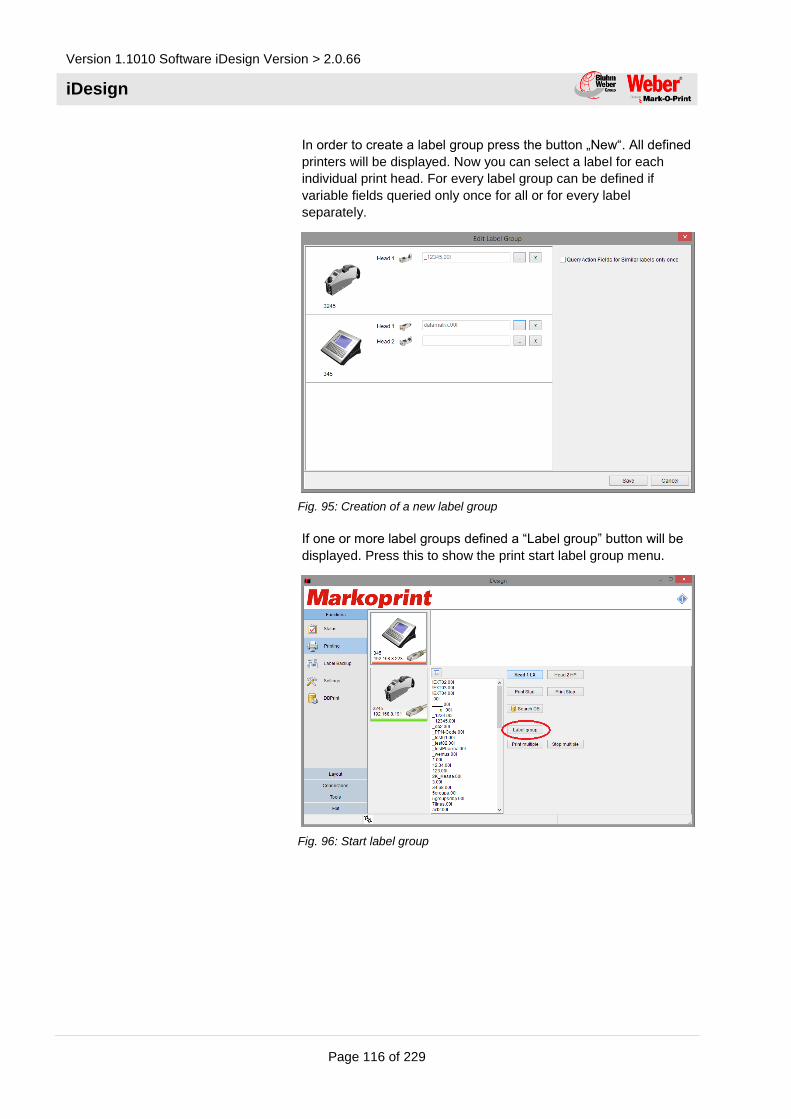
Version 1.1010 Software iDesign Version > 2.0.66
iDesign
Page 116 of 229
In order to create a label group press the button „New“. All defined
printers will be displayed. Now you can select a label for each
individual print head. For every label group can be defined if
variable fields queried only once for all or for every label
separately.
Fig. 95: Creation of a new label group
If one or more label groups defined a “Label group” button will be
displayed. Press this to show the print start label group menu.
Fig. 96: Start label group

Version 1.109 Software iDesign Version > 2.0.64
iDesign
Page 117 of 229
With the buttons you can run a print start or print
stop of the selected label group.
Fig. 97: Start / Stop label group
Database
The following settings are applied in the Database submenu:
Database selection
Settings
Fig. 98: Database menu

Version 1.1010 Software iDesign Version > 2.0.66
iDesign
Page 118 of 229
Open file
Fig. 99: Open file
Open ODBC
Fig. 100: Open ODBC link
Fig. 101: Open database
Use the “Search” button to find a specific line in the database. The
search always references the line entered in “Settings”.

Version 1.109 Software iDesign Version > 2.0.64
iDesign
Page 119 of 229
The buttons are used to navigate in the table.
The buttons at each end jump to the beginning (left) and end
(right). The two buttons in the centre move the cursor up (left) or
down (right) by one position.
The Settings tab takes you to the menu item for database settings.
Settings
Fig. 102: Database settings
The General field determines the column used for the search
function.
Fig. 103: General field
In the expiry date field, an offset can be assigned to the BBD,
determined from the database values. This means that the current
date is increased by the number shown in “Field name”. The
number in the field corresponds to the days added.
By ticking next to “User query”, the generated date can be re-
checked or changed by the user/operator.

Version 1.1010 Software iDesign Version > 2.0.66
iDesign
Page 120 of 229
Fig. 104: Calculate the expiry date field
The “Alternativ Layout” field enables download of an alternative
layout from the table. The field name for this can be defined here.
This function is switched on by ticking “active”. The name of the
alternative layout must be stored in the table. If the field is empty,
the Standard Layout remains in use.
Fig. 105: Alternativ layout field
USB Stick Backup
Fig. 106: USB Stick Backup window:

Version 1.109 Software iDesign Version > 2.0.64
iDesign
Page 121 of 229
It’s possible to save the created labels on a USB stick in the
submenu USB Stick Backup and to provide print systems with
these data.
In the saved data include:
- Label for the controller
- The fonts of the labels
- The pictures of the labels
So you use this function:
1. Open iDesign Editor USB Stick Backup
2. Click on folder and browse to your local label index.
The list of the selected index is shown in the left window.
3. Select the letter of the drive at the right side, which belongs to
your USB stick.
If there are label on the stick in the right folder structure
already, these will be shown in the right window.
Save data on a USB stick
4. Select the desired labels in the left window, which should be
saved.
5. Click on Send to save the desired label on the USB stick
or
Click on Send all to save the desired label on the USB stick,
Save data from a USB stick on a control system
6. Select the desired labels in the right window, which should be
saved.
7. Click on Receive to save the selected label in the local index,
or
Click on Receive all to save all labels in the local index.

Version 1.1010 Software iDesign Version > 2.0.66
iDesign
Page 122 of 229
Label from database
With iDesign it’s possible to create a label from a database
automatically. Thereby the database will be complete
systematically and every data set will be filled in a label and saved
separately. The created labels can be send to a print system.
To use this function:
1. Open a database and configure it that you can use it in
iDesign. See also page 117 “Database”)
2. Create or open a label with the database field.
3. Click on Label from database
Fig. 107: Choice dialog for label names
4. Select a database field for the label name in the following
dialog and confirm your choice with OK
Fig. 108: Progress window for the label creation
5. Wait until the label is created and the progress window close
automatically.
NOTE!
The labels will be saved in a subfolder in the
standard iDesign label index.
The name of the subfolder is identic with the name
of the origin label.

Version 1.109 Software iDesign Version > 2.0.64
iDesign
Page 123 of 229
Connections
Add system
1. Click on the Add system button in the Connections register.
Fig. 109: Add system
2. Now enter a unique name and IP address of the new device.
NOTE!
Manual addition of connections is only required for
Ethernet connections. USB connections are
detected and shown automatically. Serial
connections must be searched for manually using
Search at Com Ports
Search at com ports
iDesign interrogate the known serial COM-Ports one after another
to build up a serial communication to a coding system. If the
software find a coding system, this one will be linked to iDesign
and can used afterwards.
Add a system to a serial port:
1. Select Search at Com Ports
Fig. 110: Search of printers at COM-Ports
A status window opens where the search for system is shown.
If a system will be found, it is added to the software and is
shown as system symbol.

Version 1.1010 Software iDesign Version > 2.0.66
iDesign
Page 124 of 229
NOTE!
The connection persists until the finish of iDesign.
The connection is reject by closing iDesign.
If you want to retain the connection please use the
Save connection function.
Search in network
Search for Markoprint print systems in all available networks and
display of these in iDesign automatically.
NOTE!
All connections will be saved automatic. They can
given a name or can be deleted again.
Save connection
1. Select a system in the system tool bar.
2. Click in the tab Connections on the Save connection.
3. Enter a name for the system and confirm this with OK.
The selected connection will be saved and is after a iDesign
restart available.
NOTE!
The saving is not for USB-stick connections of the
X1JET available.

Version 1.109 Software iDesign Version > 2.0.64
iDesign
Page 125 of 229
Delete connection
1. Select the system in the system tool bar.
2. Select in the Connection tab the Delete connection button.
Fig. 111: Delete connection dialog
3. Confirm the shown dialog with OK
The connection to the system will be deleted. The system
symbol in the system tool bar is removed.
Update firmware
If there was a transmission error during the firmware update and
the systems can’t identified by iDesign, the firmware update dialog
can manually select with the Update firmware menu.
Start the update dialog manually:
1. Click in the Connection tab on the Restore Firmware button.
Fig. 112: Warning dialog
2. Read the warning information and confirm the dialog with OK.
3. Select the connected system below printer type.
4. Select the port where the system is connected.
5. Follow the commands for Load firmware or rather Xilings
update in the chapter „System settings System software“.
iDesign system server
The iDesign system server organizes the connection and
communication to the systems.

Version 1.1010 Software iDesign Version > 2.0.66
iDesign
Page 126 of 229
The server starts with iDesign standard. For service or diagnostics
it can be deactivated and again reactivated.
Stop server
1. Click on the Stop server button in the Connection tab to
stop the iDesign server.
After the shutdown of the iDesign server the gears don’t rotate
in the upper bar of iDesign
NOTE!
The Stop server button is only selectable if the
server runs, i.e. if the gears rotate in the status bar.
Start server
1. Click on the Start server button in the Connection tab to
start the iDesign server.
The gears rotates in the upper bar of iDesign after a
successful start of the iDesign server.
NOTE!
The Start server button is only selectable if the
server doesn’t run, i.e. the gears don’t rotate in the
status bar.
Interface logging
Fig. 113: Interface Logging
The messages, which are generated from iDesign and the
commands, which are send from iDesign to the system will be
shown in real time and saved in the Log files menu.

Version 1.109 Software iDesign Version > 2.0.64
iDesign
Page 127 of 229
Start
1. To start the real time logging,
– click on the Start logging button.
The generated system messages of iDesign are shown in
the upper window.
Stop
2. To deactivate the logging,
– click on the Stop logging button.
Delete screen
3. To delete the logo screen,
– click on the Delete button.
Save
1. To save the system messages of iDesign in a file
automatically,
– click on the Start logging button.
2. Select a folder and a file name for the log file and confirm with
Save.
NOTE!
The log file is saved in the folder „iDesign/Log/“
standard.
The standard extension for log files is „.txt“
Select one system or all systems
Select the respective system with the help of the IP address or the
name or all systems will be logged.
Fig. 114: System selection

Version 1.1010 Software iDesign Version > 2.0.66
iDesign
Page 128 of 229
Virtual systems on a USB-Stick
iDesign offers the possibilty to connect virtual systems via a USB-
stick. That means,all characteristics and data at the interface are
deposit in a special subdirectory. The required directory structure
can be create by connecting a USB-stick to a system.
If no system is available, iDesign provide virtual systems in the
folder C:\User\Public\iDesign\markoprint. Therefore the complete
folder markoprint will be copied in the main directory of a USB-
stick. The folder markoprint includes images of all current system
types. Not used systems can be deleted by removing the
subdirectories. The virtual systems will be inserted in iDesign and
will be available for all system-dependent functions by
disconnecting and connecting the USB-stick.
This function is especially useful when no data connection is
available. All operations, like print start, label backup or also
parameter settings can be done on a virtual system to realize the
operations by connect the USB-stick on a system.
Fig. 115: virt. USB – Stick print system
NOTE!
All system-depending functions, also without a
connection to the system, can be realized with the
assistence of the virtual system function.

Version 1.109 Software iDesign Version > 2.0.64
iDesign
Page 129 of 229
Tools
General settings
Fig. 116: General settings
Set up language
1. To change the actual user language, click on General
settings in the selection register Tools.
2. Select the desired language by mouse click in the list field
„user languages“. The changes come into effect partly after
restart.
NOTE!
You need a further language?
Contact Weber Marking Systems.
We can help you.
NOTE!
The changes will be assumed after the iDesign
restart.
Configurate iDesign
Automatic firmware update
The actually firmware version of the added control system
will be checked every time if this function is activated. The
user will be informed by a dialog if the firmware version isn’t
actual. The user is guided to the update process by request.

Version 1.1010 Software iDesign Version > 2.0.66
iDesign
Page 130 of 229
Fig. 117: Firmware update dialog
SystemServer
If the function is deactivated, the system server component will not
start and isn’t selectable on the surface when iDesign starts.
No systems can be administrated by iDesign in this situation.
Editor
No labels can be created with iDesign if this function is
deactivated. The menu item Editor is deactivated.
DB Print
The DB Print function is used for a serial print from databases, i.e.
of serial numbers or address print. Die DB Print Funktion dient zum
seriellen Drucken aus Datenbanken, z.B. von Seriennummern oder
Adressdruck. Standard the function is deactivate and can activate
if required. In the menu Functions is displayed this button
DB Print.
NOTE!
DB-Print can use with PRO systems only.
Store variable fields
This option specifies whether a queried variable field is saved with
print request and will be displayed as default line with a new print
request. This is useful to enter only the data that has actually
changed. Data that hasn’t changes can confirm by the Enter-
button.

Version 1.109 Software iDesign Version > 2.0.64
iDesign
Page 131 of 229
Stitch Funktion
Mit dieser Option kann die Stitch Funktion der Systeme in iDesign
verfügbar gemacht werden.
Distributor features
This function is only available for official Weber distributors and
must be considered separately.
Stitch function
The option connects several X1JET Stitch to one stitch system.
Please see also page 69.
Counter start value
The start value of a counter must be confirmed with print start or
rather the desired start value can be entered by using a counter
field in a print image with an active function. The last counter value
will be saved by a print stop and continued with a new print start.
Which counter start should be written, can be adapted.
Data type Description
From Label The defined start value in a label will be used
as counter value automatically (standard).
User input The counter start value will be queried without
standard value.
Last value The current counter value will be saved in the
label and used with a new print start.
Query last value The counter start value will be queried from
the user. Der Zählerstartwert wird vom
Benutzer abgefragt. The current counter
value is displayed as default line.

Version 1.1010 Software iDesign Version > 2.0.66
iDesign
Page 132 of 229
Settings and resources location
With the installation of iDesign a directory will be generate in
C:\users\public\. This directory includes all variable data of iDesign,
that means label, logo, font types and program settings will be
saved.
To put the settings and resources to another storage location, the
directory can i.e. be moved to a network drive. This is useful to
have access to a label trunk with multiple instances of iDesign.
Either the complete iDesign directory can be copied or there is the
possibility to use a file path of an existing iDesign directory.
Furthermore, there is the possibility to move the print images and
logo directory individually. Click on the button Change to do the
settings by a Wizzard. Also already made settings can be cancel
here.
Fig. 118: Settings and resources location

Version 1.109 Software iDesign Version > 2.0.64
iDesign
Page 133 of 229
Terminal
Fig. 119: Terminal
The terminal in the menu Tools can contact any other system
(scanner, camera…) and test the communication.
For this a connection is necessary. The connection can be
Ethernet (TCP/IP), USB, or EIA232.
Configurate TCP/IP connection
1. Select below port type TCP/IP.
2. Enter the IP address by which you want to connect.
3. Enter the port with which you want to connect.
4. Click on Connect
Configurate a USB connection
1. Select USB below port type
2. Select the desired system below USB.
NOTE!
If the desired system isn‘t in the list, click on to
refresh the list
3. Click on Connect
Configurate a RS232 connection
1. Select the port type RS232
2. Select the desired serial port below COM.
NOTE!
If the desired port isn‘t in the list, click on to
refresh the list

Version 1.1010 Software iDesign Version > 2.0.66
iDesign
Page 134 of 229
3. Select the baud rate, data bits, parity and the number of stop
bits.
4. Click on Connect.
Connection status
Besides the Connect button is a LED, which displays the status of
the connection with 3 colors.
Color Meaning
Grey No connection
Yellow Link connection
Green Establish connection
A direct communication to the print systems is also possible with
the terminal. The commands will be sent to the print system via the
existing connection.
CAUTION!
The incorrect use of the terminal can cause data
loss and failures of the print system.
CAUTION!
iDesign didn’t check the correct spelling of the
commands.
The terminal translated the used control characters of the
Markoprint systems into its hexadecimal correspondents
automatically before it is send to the print system.
Send interval
If one or more commands should send continuously, it can start
with the icon . The interval length can specified in ms.
Send command
1. Type the desired command in the command window.
2. Click on Send
… The commands will be send to the coding
systems. The answer of the system is shown in the
lower window.

Version 1.109 Software iDesign Version > 2.0.64
iDesign
Page 135 of 229
NOTE!
The terminal allows the sending of sperate ascii
signs. This must be specified in form <0x01> (for
<SOH>) in hexadecimal spelling.
Use command templates
1. Select the desired template in the upper drop-down menu.
The included command is added in the upper terminal
window.
NOTE!
Lines, which begins with „//“ are comments and are
not send.
2. Click on Send
… The commands will be send to the coding
systems. The answer of the system is shown in the
lower window.
Load commands
1. To load already saved commands click on Open
2. Browse by the file dialog to the desired file.
NOTE!
The file extension for template files is .ast
3. Open loads the data content of the file in the upper terminal
window.
4. Click on Send to send the commands to the coding system.
The file „Interface Commands.ast“ is in the list. Here are prepared
all commands of the iJET / X4JET with a short description.
Save commands
1. Click on Save to save the currently shown commands in the
upper terminal window.
2. Select the file dialog, a name and a storage location and
confirm with Save..

Version 1.1010 Software iDesign Version > 2.0.66
iDesign
Page 136 of 229
USB Firmware Update
Fig. 120: Terminal
You can program USB memory systems with the USB-firmware
update so, that you can make a firmware update on corresponding
systems.
NOTE!
The USB-Stick Firmware Update is only available
for iJET, X-Serie.
Create a USB-Firmware Stick
1. Click on USB Stick Firmware in the menu Tools
It opens a dialog to create firmware USB-sticks
2. Select the desired system classification in the menu Printer
type.
3. Afterwards select the desired firmware version that should be
installed in the menu Firmware.
4. Insert an USB-stick in a free port of the PC.
The drive of the USB-stick is added to the drop-down
menu automatically.
5. The drop-down menu USB-Stick shows all available
removable medium of the system, select your USB-stick here.
NOTE!
Drive letter of the USB-stick can be look up in the
Windows file explorer or rather below desktop
6. Click on Start to start the programming operation.
It appears a window that informed about the programming
level.
The window closed after a successfully installation.

Version 1.109 Software iDesign Version > 2.0.64
iDesign
Page 137 of 229
NOTE!
Files and folders, which exist on the USB-stick
already and collide with the actual firmware update,
will be moved to the folder „MOP_FW_Backup”.
Software-Update of the system
unit:
iJET / X4JET USB Update (offline)
1. Switch the system on and hold the iLOGIK pressed if the start
logo appears.
2. On the display is shown:
Stick?
3. Insert the USB-stick with the new version.
4. On the display is shown:
Copy to SD?
With a short pressure on the iLOGIK, the new version is copied
to the internal SD-card and the system restarts
XB4JET / XB8JET USB Update (offline)
1. Switch the system on and hold the start button beside the power switch pressed.
2. Wait until the status LED flashes red/green.
3. Insert the USB-stick with the new version.
4. The sensor LED flashes yellow/red if the program is load.
5. With a short pressure on the OK button the system restarts.
6. The status and senso LED flashes red after ca. 15 sec. At the same time you can hear the relays clicking. Now press the start button again.
7. After ca. 15 seconds the restart is finished (again clicking of
the relays) and the USB-stick can be removed.

Version 1.1010 Software iDesign Version > 2.0.66
iDesign
Page 138 of 229
X2JET / X4JET Plus USB Update (offline)
1. Switch the system on and hold the info-button pressed if the
start logo appears.
2. On the display is shown:
Stick?
3. Insert the USB-stick with the new version.
4. On the display is shown:
Copy to SD?
5. With a short pressure on the OK button, the new version is copied to the internal SD-card and the system restarts.
6. On the display is shown: Copy HMI Data from Stick?
7. Press the OK-button to confirm this. The data for the user interface will be updated. Concluding the system restarts.
X1JET USB Update (offline)
1. Connect the device to the power supply, press the [Ink]-
BUTTON and hold them pressed until the sensor LED flashes green/red.
2. Insert the USB-stick into the USB socket on the top side of the system.
3. The sensor LED flashes yellow/red if the program is load.
4. Confirm it by pressing the start-button and wait until the system restarts.
5. Now remove the USB-stick

Version 1.109 Software iDesign Version > 2.0.64
iDesign
Page 139 of 229
User Management
Overview
The iDesign user management facilities allows for access to
dedicated features of iDesign based on user name and password
identifiers. In this regard, it follows the standard approach, which
most users are familiar with, from i.e. the Windows operating
system and many more.
However, because there are many different requirements on how
to manage user credentials in the field of industrial applications,
iDesign comes with three different flavors of user management.
The list below provides a short overview of those:
Type Characteristics
Simple user Management Three fixed access levels.
Passwords are to be chosen at first configuration and can be changed later on.
Credentials for each level can be changed as well.
Advanced User
Management
Unlimited number of users and user groups. One can assign any number of
credentials to a user group which can, in turn, can contain any number of users.
GAMP Advanced User
Management
Like above with an enhanced and more restrictive security model.
Each of the user management systems covers some requirements
that motivate the use of user based access to iDesign features. In
the following section we would like help you, to find out which
approach will fit your needs. Additionally, we will provide a more in
depth explanation of the features provided.

Version 1.1010 Software iDesign Version > 2.0.66
iDesign
Page 140 of 229
Simple User Management
This type of user management provides three fixed access levels.
The passwords, needed to access one of the levels, can be
adjusted during activation of the user management. The
passwords, as well as credential details, can be changed later on
but note that this can only be done by the level “Administrator”.
Each of the access levels can be configured, except the admin
level which is fixed to have all available credentials. This is mainly
to prevent the admin level from lock itself out from the system.
If your primary reason for the use of a user management is just to
keep control of the current settings of your connected devices, thus
keep shift workers away of the more sophisticated settings of the
devices, then you are probably best off, using the simple user
management. Please, refer to the section Setting up the simple
user management, to learn how to configure it.
Guest credentials
If User Management is activated in iDesign, one has to type in a
password in order to do even the most basic tasks. Sometimes,
this behavior is too restrictive. You want, for example, a line worker
to be able to observe the status of some printers or want them to
be able to start and stop print jobs without the need to log in each
time. This can be achieved by setting up the standard user as a
guest account. If this option is enabled, the standard user is
automatically in logged in state after iDesign is started and it has
no password assigned. However, you can still restrict some of the
more sensible features of iDesign using the admin and super user
access levels.
Advanced User Management
The need to use this mode of the user management arises if the
access levels, provided by the simple user management don’t fit to
the kind of personnel that works in your factory, i.e you need to
have more than three types users that will use iDesign. In this
case, you will need to define your own access levels. Furthermore,
you may want to provide each user with an unique log in /
password for his own use, instead to have just one “common”
password to use for all employees that should log in using a
distinctive access level.
Once, the advanced user management is activated, the dedicated
“admin” user can create an unlimited number of users. Each user
will have a unique login-name and a password. Users are always
member of a user group. A user group in turn will have several
credentials attached. The admin user can add or remove credential
from each user group as required. Find an exhaustive list of all
available credentials in the appendix A.
Guest Account
In the same manner as in the Simple User Management, it's
possible to create a guest user, that will become active when no

Version 1.109 Software iDesign Version > 2.0.64
iDesign
Page 141 of 229
other user is logged in and which is logged in immediately after
start of iDesign.
Please, refer to the section Setting up the Advanced User
Management to learn more.
GAMP Advanced User Management
If you need enhanced security features and a close monitoring of
user activities, then the GAMP User Management is the correct
choice for you. The GAMP Management is similar to the Advanced
User Management, in terms of user and user groups but provides
some features that are not needed by all customers, therefore we
decided to provide those features as an extra option.
In particular those features are:
• Users that are created by the admin user will be asked to
change their password after the first successful logon.
• If a user tries three times to dial in without success, this user
will be locked. That means, this user cannot log in anymore.
Only the user “admin” is able to unlock this user again, by
providing her / him a new password (that she or he will need
to change after first login, again).
• After 5 Minutes of inactivity a user will be automatically
logged out.
• Use actions will be captured in a log file.
Please, refer to the chapter activate GAMP User Management and
Configuration of the GUMP User Management for further details.

Version 1.1010 Software iDesign Version > 2.0.66
iDesign
Page 142 of 229
Tutorial
Setup the Simple User Management
Fig. 121: User management
1. Start iDesign
2. Select the menu “tools”
3. Press button “user management”.
4. A new window will appear. Select the choice “simple user
management”.
5. Press “Next”
Fig. 122: User management
6. Now, you need to insert three passwords. You will need to
enter each password twice. If you typed all the passwords
correct, the “next” button is enabled. If you cannot press this
button, that means that one of the passwords is not typed
correctly.
7. If everything went well, press “next”. iDesign will shut down
and restart.

Version 1.109 Software iDesign Version > 2.0.64
iDesign
Page 143 of 229
Setup the Simple User Management with guest user.
1. Start iDesign
2. Select the menu “tools”
3. Press button “user management”.
4. An new window will appear. Select the choice “simple user
management”.
5. Press “Next”
Fig. 123: User management
6. Now, type in the passwords for the admin user and super user.
You can leave the entries for the standard user blank. You will
note, that you need to type each of the passwords twice.
7. Tip the automatic login checkbox inside the standard user
group box.
8. Click the finish button. iDesign will restart.

Version 1.1010 Software iDesign Version > 2.0.66
iDesign
Page 144 of 229
Using iDesign with Simple User Management enabled
Login after start
Fig. 124: Login
1. Start iDesign. You will notice that most buttons and controls
are in gray color and that they don't react on mouse clicks.
2. To log in press the button at top right side of the main screen
as shown in the image above.
3. In the dialog window that will appear now, select first the kind
of access level that you want to enter.
4. After that type the password in the input field below.
5. Press ok to log in.
Change the current access level
See log in after start.
Log out
1. Press the small black arrow near the login button.
2. On the menu that will appear then, select logout.
3. You will be asked if you really want to log out. Confirm by
pressing the Ok button.
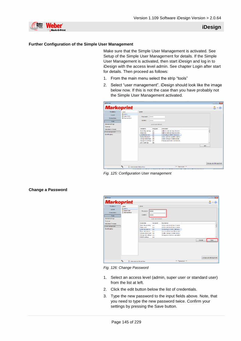
Version 1.109 Software iDesign Version > 2.0.64
iDesign
Page 145 of 229
Further Configuration of the Simple User Management
Make sure that the Simple User Management is activated. See
Setup of the Simple User Management for details. If the Simple
User Management is activated, then start iDesign and log in to
iDesign with the access level admin. See chapter Login after start
for details. Then proceed as follows:
1. From the main menu select the strip “tools”
2. Select “user management”. iDesign should look like the image
below now. If this is not the case than you have probably not
the Simple User Management activated.
Fig. 125: Configuration User management
Change a Password
Fig. 126: Change Password
1. Select an access level (admin, super user or standard user)
from the list at left.
2. Click the edit button below the list of credentials.
3. Type the new password to the input fields above. Note, that
you need to type the new password twice. Confirm your
settings by pressing the Save button.

Version 1.1010 Software iDesign Version > 2.0.66
iDesign
Page 146 of 229
Fig. 127: User management settings
Change the credentials
1. Select an access level (admin, super user or standard user)
from the list at left.
2. Click the edit button below the list of credentials.
3. To add a new credential to the selected access level, click on
the check box near the description of the credential. To
remove already assigned credentials remove the tick in the
box by a mouse click.
4. Confirm your changes by pressing the Save button.
NOTE:
It is not possible to add or to remove any credentials from the
admin access level.
Select an access level as guest level
1. Select an access level
2. Click the edit button.
3. Tick the login automatically check box.
4. Confirm your changes by pressing the Ok button.

Version 1.109 Software iDesign Version > 2.0.64
iDesign
Page 147 of 229
Advanced User Management Setup
Fig. 128: Setup user management
1. Start iDesign
2. Select the menu “tools”
3. Press button “user management”.
4. A new window will appear. Choose “Advanced user
management”.
5. Press “Next”
Fig. 129: Enter Password
6. Enter the administrator password. Note that you must repeat the password for security reasons. Note as well that you must log in to iDesign using this password to do any further settings. If this password get lost, you are probably locked out from iDesign at all.
7. Press “finish”. IDesign will restart. The Advanced user management is active now.

Version 1.1010 Software iDesign Version > 2.0.66
iDesign
Page 148 of 229
Advanced User Management setup with guest user
Fig. 130: Setup guest user
1. Follow the steps, described in the chapter Advanced user
management setup up to step 6.
2. Now click the check box “create” which his to be found in the
group box “standard user without login”.
3. Press “finish”.
Using iDesign with advanced user management enabled
Log in after start
Fig. 131: Login
1. Start iDesign. You will notice that most buttons and controls
are in grey color and that they don't react on mouse clicks.
2. To log in press the button at top right side of the main screen
as shown in the image above.
3. In the dialog window that will appear now, type in your user
name and password.
4. Press ok to log in.

Version 1.109 Software iDesign Version > 2.0.64
iDesign
Page 149 of 229
Log out
1. Press the small black arrow near the login button.
2. On the menu that will appear then, select logout.
3. You will be asked if you really want to log out. Confirm by
pressing the Ok button.
Further setup of the advanced user management
Make sure that the Advanced User Management is activated.
Advanced user management setup for details. If the advanced user
management is activated, then start iDesign and log in to iDesign
using the admin user. See chapter Login after start for details.
Fig. 132: Setup user management
Proceed as follows:
1. From the main menu select the strip “tools”
2. Select “user management”. iDesign should look like the image
below now. If this is not the case the advanced user
management is not active.
Create a new user group
Fig. 133: Setup user group

Version 1.1010 Software iDesign Version > 2.0.66
iDesign
Page 150 of 229
1. Click on the button “new group”
2. In the input field of the new dialog, type the name of the new
user group. Note that it's not permitted to create 2 groups with
the same name.
3. Press “ok” to save the group.
Delete a user group
Fig. 134: Delete user group
1. In the list of group entries to the left, select the group that you
want to delete.
2. Click the “delete group” button. Note that it's not permitted to
delete a group with assigned users. In this case, the “delete
user” button will appear in gray and will not react to user input.
You will need to delete all the users in the group one by one
before the group can be deleted.
3. After pressing the delete button, iDesign will ask you confirm
your decision by pressing an “Ok” button.
Assigning or removing credentials
Fig. 135: Setup user management

Version 1.109 Software iDesign Version > 2.0.64
iDesign
Page 151 of 229
1. Select a group from the list
2. Click on the tab “credentials”
3. To set a credential, click on the check box in a list entry.
Credentials which are already assigned to a user group will
appear with a tick in the box. To remove the credential, you
can remove the tick.
4. Don't forget to confirm your changes by pressing the “save”
button below.
Create a new user
Fig. 136: New user
1. Select the group to which you want to assign the new user
2. Click on the tab header tiled “users of” followed by the name of
the selected group
3. Press the button “add user”
4. In the dialog window that will appear now, please fill in all the
input fields. You will need to insert the password twice. As
soon as all entries are correct, the “ok” button will become
enabled.
5. Press “Ok” to save the new user.

Version 1.1010 Software iDesign Version > 2.0.66
iDesign
Page 152 of 229
Edit user details
Fig. 137: Setup user management
1. Select a user from the list in page center.
2. Click the “edit” button
3. Change the name and surname entries as required. Note, that
it's not possible to change the log in identifier of an user.
4. If you need to change the password of an user, tick the check
box “set new password”
5. You need to type the password twice, for safety.
6. Confirm your changes by pressing the “save” button.

Version 1.109 Software iDesign Version > 2.0.64
iDesign
Page 153 of 229
Delete users
Fig. 138: Delete user
1. Select the user that you want to delete
2. Press the “delete user” button. Note that it's not permitted to
delete the user Administrator.
3. Confirm by pressing ok on the dialog.
GAMP User Management Setup
Fig. 139: Setup User management
1. Start iDesign
2. Select the menu “tools”
3. Press button “user management”.
4. A new window will appear. Select the choice “GAMP user
management”.
5. Press “Next”

Version 1.1010 Software iDesign Version > 2.0.66
iDesign
Page 154 of 229
Fig. 140: Enter password
6. Type the password for the admin user. You will need this
password later on so make sure that you typed it exactly as
you intended. A typing error in your password will lock you out
permanently from the system.
7. Press “finish”. iDesign will restart. For further settings, log in to
iDesign using the log in name “admin” and the password that
you created in step 6.
Further setup of the GAMP user management
Detailed setup und configuration of the GAMP user management is
similar to the Advanced user management. Please, refer to the
chapter further setup of the advanced user management for
details.

Version 1.109 Software iDesign Version > 2.0.64
iDesign
Page 155 of 229
Specifics of the GAMP user management
The GAMP user management resembles all features of the
advanced user management. However, there are some additional
security enhancements.
• A user that logs in the first time to iDesign will need to change
her or his password in order to proceed to the main screen.
This will happen only once, for the sake of increased security.
• If a user will type three times consecutively a wrong password,
he or she will be locked out from the system permanently. The
user in question will need to approach the admin user and ask
him or her to apply a new password. After that, the lock is
removed.
• iDesign will log off a user automatically if it receives no input by
mouse or keyboard for more than five minutes. After this period,
the user must log in again.
Troubleshooting
What if the admin password got lost?
If you locked yourself out of the system or the admin password is
lost, please, contact the Bluhm Weber Support Team.

Version 1.1010 Software iDesign Version > 2.0.66
iDesign
Page 156 of 229
Appendix
List of available credentials
Print Start / Stop Access to the “Print” button of the “functions” menu
Status view Access to the “Status” button of the “functions” menu
Label backup Access to the “Label Backup” button of the
“functions” menu.
Basic Device Settings Access to the “Print Parameters” settings strip in the
“settings” form of the “functions” menu.
Change Device Type Access to the “Device Setup” slider in the “settings”
form of the “functions” menu.
Change Ink Settings Access to the “Spitting and Warming” slider in the
“settings” form of the “functions” menu.
Change Head Setup Access to the “Head Setup” slider in the “settings”
forms of the “functions” menu.
Change IO Settings Access to the “IO Output” slider in the “settings”
forms of the “functions” menu.
Database Settings Access to the “Database Connection” button in the
“Layout” menu.
Edit Labels Access to the “Editor” button in the “Layout” menu.
USB Backup Access to the “USB Backup” button in “Layout”
menu.
Labels from DB Access to the “Create labels from DB” button in the
“Layout” menu.
Add Devices Access the buttons “Add ethernet connection”,
“search network”, “search com ports”, “Save” and
“Delete” on the “Connections” menu.
Start / Stop server Access the buttons “Start server” and “Stop server”
on the “Connections” menu.
Update Firmware Access the button “Update Firmware (Legacy)” on
the “Connections” menu.
General Settings Access the button “General Settings” in the “Tools”
menu.
Logfiles Access the button “Interface logging” on the “Tools”

Version 1.109 Software iDesign Version > 2.0.64
iDesign
Page 157 of 229
menu.
Terminal Access the button “Terminal” on the “Tools” menu.
USB Firmware Access the button “USB Stick Firmware” on the
“Tools” menu.
Event log Access the button “Event logging” on the “Tools”
menu.
User management Access the button “User Management” on the tools
menu
DB Print Access the button “DB Print” on the “functions”
menu.

Version 1.1010 Software iDesign Version > 2.0.66
iDesign
Page 158 of 229
User management on the systems
The Markoprint systems have, like iDesign, an integrated user
management.
iDesign offers therefore the possibility to manage the user on the
systems. The user management on the systems offers two
characteristics.
To create, change and delete user.
To change access levels on separate system menus.
Features
The user management for systems has some features that differ
from the user management in iDesign.
1. Max. 12 additional users can be created in the system.
2. Unblocking or blocking of separate menus in the system works
only if the system is controlled via TCP/IP. This function isn’t
available if the system is connected via USB or serial.
3. Standard is one user on each system: User „Free“ has access
level 9. To use the user management wise, the user „Free“
(standard user) must have an access level less than 9.

Version 1.109 Software iDesign Version > 2.0.64
iDesign
Page 159 of 229
Operation
Fig. 141: Change user or access levels
To change user and access levels on the systems, the simple or
advanced user management must also activate in iDesign. Please
see chapter „iDesign User Management“ to set up the simple user
management in iDesign.
After the activation of the user management, start iDesign and
register as administrator. Select the system, on which you want to
change the user or access levels and click on settings.
Select the tab Passwords.
Block standard user
Fig. 142: Edit user
To reach that users can register on a system, the rights of the
standard user „Free“ must change. Select the user “Free” and click
on the button Edit User. Select another authority than 9 and click
on OK.
With Level 1 all menus are blocked.

Version 1.1010 Software iDesign Version > 2.0.66
iDesign
Page 160 of 229
Add user
Fig. 143: Add user
1. Click the button Add User.
2. Enter a user name, the access level and password in the sub-
window.
3. Confirm with OK.
Change access level of an user
1. Select the user from the list.
2. Click on Edit User.
3. Select the new access level of the user in the dialog.
4. Confirm with OK.

Version 1.109 Software iDesign Version > 2.0.64
iDesign
Page 161 of 229
Delete user
Fig. 144: Delete user
1. Select the user from the list.
2. Click on Delete User.
3. Confirm with OK.
Access levels for menus
Fig. 145: Access levels
1. Start iDesign and register as administrator to change the
access authorization for a menu of the system.
2. Select the system whose authorization you want to change.
3. Click on Settings in the main menu and select the tab Device
Users. Now select the tab Access Levels.

Version 1.1010 Software iDesign Version > 2.0.66
iDesign
Page 162 of 229
Change the access level for a menu
Fig. 146: Change access levels
1. Select the menu you want to change.
2. Click on Change.
3. Select the new access level for this menu in the dialog.
4. Confirm with OK.
5. Restart the system after loading the new access levels on the
system. The changes are effective now. Therefore iDesign
shows a small dialog. You can also resign an immediate
restart if you click on Cancel.

Version 1.109 Software iDesign Version > 2.0.64
iDesign
Page 163 of 229
Operation iJET / X4JET
A password was assigned, i.e. a password is required for the
parameter to enter the menu: „password level 4“.
Now a password of a user must be entered, who has the rights for
level 4 or higher.
If an incorrect password is entered or there is no permission, the
menu doesn’t open.
After 5 minutes without using it is logged out automatically.
If you want to logout before, press the iLogik button in the status
for 3 seconds. It appears “Locked!” on the display.
Operation X2JET plus / X4JET plus
A password was assigned, i.e. a password is required for the
parameter to enter the menu: „password level 4“.
Now a password of a user must be entered, who has the rights for
level 4 or higher.
If an incorrect password is entered or there is no permission, the
menu doesn’t open.
After 5 minutes without using it is logged out automatically.
If you want to logout before, press on the info button in the main
screen shortly.

Version 1.1010 Software iDesign Version > 2.0.66
iDesign
Page 164 of 229
Event Logging
If the user management is active, all user inputs are listed in the
event logging.
Font Creator
The font creator is used to generate Markoprint print fonts from
Windows TrueType fonts. The delivered standard character set of
the print system can add with new sizes and fonts, like i.e. Cyrillic.
Fig. 147: Font Creator
Procedure:
1. To start the font creator, click in the menu Tools on the
submenu Font Creator.
2. Select the required printer type. Important is the used print
technology, i.e. Trident – MX.
3. Click on the button Next.

Version 1.109 Software iDesign Version > 2.0.64
iDesign
Page 165 of 229
Fig. 148: Font parameter
4. Select the font name and height in mm. It can also select an
international character set.
5. Click on the button Next.
Fig. 149: Font Creator package
6. Now you have the possibilty to select, whether a single font or
a font package with all sizes should create for the selected
printer type.
7. Click on the button Next.

Version 1.1010 Software iDesign Version > 2.0.66
iDesign
Page 166 of 229
Single font
With the option single font you have the possibilty to edit the
character set with Paint.
Therefore click the button Edit.
Fig. 150: Edit with Paint
1. Click on the button Next to save the character set.
Fig. 151: Save single font

Version 1.109 Software iDesign Version > 2.0.64
iDesign
Page 167 of 229
NOTE!
Use a name to arise from the font height to
guarantee an assignment for the print image
creation.
Font package
Specify a name for a new font package by enter a name code for
the first segment. A letter is therefore enough. The second
segment is provide with the height information automatically by the
creation. Following there is the possibility for an addition like, i.e. B
for bold.
Fig. 152: Define a name for a font package
The standard font folder is offered as target directory.
NOTE!
The fonts can also save in other folder, but are
available for the print image creation.
Create and save
Specify a name for the new font package by enter a name code for
the first segment. A letter is therefore enough. The second
segment is provide with the height information automatically by the
creation. Following there is the possibility for an addition like, i.e. B
for bold.

Version 1.1010 Software iDesign Version > 2.0.66
iDesign
Page 168 of 229
Fig. 153: Create and save
NOTE!
The new created fonts can used for the print image
creation now.
NOTE!
It isn’t necessary to copy the new fonts in the print
system manually. The new fonts will send
automatically with the print start of iDesign or by
sending the print image in the print system.

Version 1.109 Software iDesign Version > 2.0.64
iDesign
Page 169 of 229
Signal Analysis
This function is useful for displaying and checking recorded signal
flows and complete configuration and adjustments of a printer. It is
also possible to complete this report with a individual comment.
More information regarding the signals is to find at site 34 and
follows.
Fig. 154: Signal Analysis – Show configuration and parameters
Fig. 155: Signal Analysis – Show and analyze stored signal flow

Version 1.1010 Software iDesign Version > 2.0.66
iDesign
Page 170 of 229
iDesign Touch structure
Main menu
Fig. 156: iDesign Touch structure, Main menu
1 iDesign Touch functions
2 Field for print image
3 System functions
4 Status display / Signal lamps
5 Field for screen keyboard / systems
6 Stop program /switch off / version info
Back button if you are in a submenu
7 Call up screen keyboard
1
2
3
4
5
6
7

Version 1.109 Software iDesign Version > 2.0.64
iDesign
Page 171 of 229
Status displays / Signal lamps
Symbol Function Description
Ok Print mode started up and ready to
print.
Warning Print mode interrupted (pause).
Ink cartridge only 5 % full.
Alarm Print mode not ready to print.
Ink cartridge is empty.
Cartridges Fill level of the cartridges
The presentation of the print systems in the toolbar happens with
the IP address and a status display.
System functions
Symbol Function Description
Start Activate the print mode.
Call the layout up for print.
Pause Print pause, variables and
counter will be retained, by
pressing this button again,
printing is resumed.
Pause / Stop Interrupt print mode.
The print storage will be
deleted.
Settings Settings of the selected
system
Status Information of the
operation status of the
corresponding system

Version 1.1010 Software iDesign Version > 2.0.66
iDesign
Page 172 of 229
iDesign Touch functions
Symbol Function Description
Menu Editor Calls up the Editor
menu where the print
images are created.
Menu Setup Calls up the Setup
menu where basic pre-
settings are performed.
Menu Action
log
Calls up the Action log
menu – shows the
action protocol of the
system.
Toogle functions
Symbol Function Description
Close Terminates application and switches off
the controller.
Back Returns to main menu.
Maximize Maximize the display of the Editor-print
range
Minimize Minimize the display of the Editor-print
range
Call up the screen keyboard
An on-screen keyboard, that can be faded in or out as required, is
available for the entry of text and parameters.
The on-screen keyboard can be used like a normal PC keyboard
and is available in each menu.
NOTE!
If the on-screen keyboard is faded in, the status displays
are not visible.
To call up the on-screen keyboard,
1. Select the button.
The on-screen keyboard is faded in at the bottom half of
the screen.

Version 1.109 Software iDesign Version > 2.0.64
iDesign
Page 173 of 229
Arrow keys
Symbol Function Description
Arrow key
left
Move highlighted field in print image to
the left, pixel by pixel.
Move the cursor in a text to the left.
Arrow up Move highlighted field in print image up,
pixel by pixel.
Move up the cursor in a text.
Arrow key
down
Move highlighted field in print image
down, pixel by pixel.
Move down the cursor in a text.
Arrow right Move highlighted field in print image to
the right, pixel by pixel.
Move the cursor in a text to the right.
Fig. 157: Main menu with screen keyboard

Version 1.1010 Software iDesign Version > 2.0.66
iDesign
Page 174 of 229
System functions
Load print image
The print image in print memory is printed on the product surface
by the print heads after each impulse from the light barrier.
To load a print image into the print memory,
1. Touch the button in the main menu.
The file dialog opens.
Fig. 158: File dialog
2. In the Open file field, press the print image and highlight.
Alternatively, the required print image name can be entered in
the File name field and confirmed with ENTER
The print image appears in the Preview window.
3. Confirm with Ok.
The print image is loaded into print memory and displayed in the
main menu.
For systems with multiple heads, a print image can start on all
heads:
Fig. 159: Print start
The signal lamp lights up and the status display shows
the current print mode.

Version 1.109 Software iDesign Version > 2.0.64
iDesign
Page 175 of 229
The print mode is terminated by pressing the button. By
pressing this button again, printing is resumed. Entered variable
values and counter statuses are retained.
If is pressed after the most recently printed text
is re-loaded; variables must be re-entered; the counters re-start
with the starting value.
With pressing the „Stop“ button the print buffer will be cleared. By
pressing the “Start” button a new print image can be selected and
printed.
Display print storage
On the main-screen you see the actual print image that is printed.
This image is a direct capture from the print storage. This image
will be printed.
Fig. 160: Print storage

Version 1.1010 Software iDesign Version > 2.0.66
iDesign
Page 176 of 229
Menu Settings
Basic parameterisation must be performed in the Settings menu
before the print system is able to print.
The Settings menu has the following submenus:
Submenu Description Page
Print heads To specify the print parameter,
print head settings, spitting and
warming, calibration and
configuration of the inputs.
176
System System settings, setting of the
in- and outputs and interface
EIA232.
188
Logging Messages, which are generated
from iDesign and commands,
which are send from iDesign to
the system will be shown in real
time and saved in the Log files
menu.
198
Submenu print heads
In the sub-menu Cartridges the following parameters can be
modified:
Print parameter
Print head setup
Spitting and Warming
Calibration
Input configuration
To display the Print head submenu,
1. Select the button in the main menu.
The Settings menu opens.
2. Click in the Settings menu the submenu Print head.

Version 1.109 Software iDesign Version > 2.0.64
iDesign
Page 177 of 229
Fig. 161: Submenu Print heads
Tab Print parameter
Print delay
The parameter print delay defines the path distance in mm
between the light barrier trigger by the product and start of
printing. By setting such a print delay, the position of the print
image on the product can be changed. The print delay can be
specified for each print head.
Adjustable values: 0 to 999 mm.
The value 0 means that printing can be triggered immediately
after the light barrier trigger pulse.
1. Press tab Print head 1 or Print head 2 (depends on the
number of the activated print heads) and select the desired
print head.
2. To set the delay,
– Press arrow keys and set the required delay value.
The value is accepted as soon as the arrow keys are
released
or:
– Enter the delay value via the on-screen keyboard and
confirm with the Enter key on the keyboard
The figures originally displayed in red are displayed in black
after confirming with the Enter key.

Version 1.1010 Software iDesign Version > 2.0.66
iDesign
Page 178 of 229
NOTE!
The print start delay must not be greater than the
distance between 2 products. If a print start is
triggered before the last print is finished, it will be
ignored.
Speed in m/min / Intensity / Zoom
The print speed of the print heads must match the conveyor belt
speed, otherwise print images may be distorted.
There are 2 ways to match the print speed to the conveyor belt
speed:
Internal constant print speed.
External variable print speed via rotary encoder
.
If no rotary encoder is connected to the controller, the conveyor
belt speed must be measured or estimated and the determined
value entered as a parameter. A test image can then be used for
fine-tuning the print speed. The set print speed is applicable for the
selected print head group.
For single heads head 1 and 2 have the same setting and can’t set
separately.
The following parameters must be entered:
Print speed
Print speed = Conveyor belt speed. The conveyor belt speed
must remain constant!
Intensity
Print image contrast. If necessary, this parameter may have
to be changed to optimise the print image to the product
surface. Higher intensity means increased density and
slower drying of the ink.
Print width/Zoom
This parameter enables an increase or decrease of the
number of pixels. This renders the print image wider or
narrower.
HINWEIS!
NOTE!
When printing barcodes, ensure that widening or
narrowing occurs only in the correct ratio. Note the
optimal print intensity of 300 dpi. Observe the
following table!

Version 1.109 Software iDesign Version > 2.0.64
iDesign
Page 179 of 229
Barcode width Permitted zoom factor [%]
1 100, 200
2 50, 100, 150, 200
3 66, 100, 133, 166, 200
4 50, 75, 100, 125, 150, 175, 200
5 60, 80, 100, 120, 140, 160, 180, 200
6 50, 66, 83, 100, 116, 133, 150, 166, 183, ...
Parameter Min. Max. Unit
Print speed 1,0 400,0 m/min
Intensity 50 900 dpi
Zoom 10 900 %
To enter the print speed, the print intensity and the print width /
zoom,
– Press arrow keys and set the required value.
The values are accepted as soon as the arrow keys are
released.
or:
– Press and highlight the input field.
– Enter the values via the on-screen keyboard and confirm
with the Enter key on the keyboard.
The figures originally displayed in red are displayed in black
after confirmation with the Enter key.
Print direction
The Print direction parameter specifies the direction in which the
product moves on the conveyor belt as viewed from the print head
side.
1. Press tab Print head 1 or Print head 2 (depends on the
number of the activated print heads) and select the desired
print head.
2. Specify the direction of the conveyor in the dropdown menu.

Version 1.1010 Software iDesign Version > 2.0.66
iDesign
Page 180 of 229
Nozzle row
Each ink cartridge has two nozzle rows (A and B). One nozzle row
has 150 nozzles.
The nozzles in row A print the uneven numbers 1, 3, 5, 7 …
The nozzles in nozzle row B print the even numbers 2, 4, 6, 8…
Per nozzle row A ~ B, 300dpi are printed vertical.
In this mode, the nozzles are uniformly stressed and the speed
setting is not as critical as with A + B.
If, for instance, using A ~ B, every second print image is of poor
quality, nozzle row A or nozzle row B can be activated.
Both nozzle rows print simultaneously with the setting A+B. The
vertical resolution is 600 dpi. The print image is dark equal. The
speed must be exactly right, because this will cause a shadow or
blurred print when the nozzle rows are not print about each other
correctly.
Activate the nozzle rows as follows:
Nozzle row Description
A ~ B Printing with both nozzle rows, alternating.
The first print image is printed with nozzle row A and the
second text with nozzle row B.
A + B Printing with both nozzle rows together.
Vertical resolution: 600 dpi
A Printing only with nozzle row A.
Vertical resolution: 300 dpi
B Printing only with nozzle row B.
Vertical resolution: 300 dpi
NOTE!
With setting A + B, the print speed must be accurately
set, to produce a good print result. Otherwise the print
image is blurred.
To select the nozzle row,
1. Press tab Print head 1 or Print head 2 (depends on the
number of the activated print heads) and select the desired
print head.
2. Select the desired nozzle row setting in the dropdown
menu.

Version 1.109 Software iDesign Version > 2.0.64
iDesign
Page 181 of 229
Upside Down
The setting Upside Down causes the print image to be printed
upside down.
To select upside down,
1. Press tab Print head 1 or Print head 2 (depends on the
number of the activated print heads) and select the desired
print head.
2. Activate upside down in the dropdown-menu.
Repeat distance / Print repeat number
To print several print images on one product, the number of print
images and the distance between them must be specified.
The distance between print images is measured from print start to
print start.
If you select „5“ the print image will be printed 6 times. 1 print plus
5 repeats.
998 prints 999 print images.
Endless printing can be activated with print repeat of „999“.
Parameter Min. Max. Unit
Distance between print images 0 9999 mm
Number of print images 0 999 -
To enter the repeat distance and the print repeat number,
– Press arrow keys and set the required delay value.
The values are accepted as soon as the arrow keys are
released.
or:
5. Press and highlight the input field.
– Enter the values via the on-screen keyboard and confirm
with the Enter key on the keyboard
– Endless printing can be activated with a click on the
button at the print repeat number. The value goes to 999
automatically.
The figures originally displayed in red are displayed in black
after confirmation with the Enter key.

Version 1.1010 Software iDesign Version > 2.0.66
iDesign
Page 182 of 229
Reverse print delay
Is the print direction backward, i.e. the product moves on the print
head from left to right, the calculation point for the print start delay
can set to right or left edge of the print image.
The setting „left border“ ensures a consistent left alignment.
It should be noted that the width of the print image needs to be part
of the set value.
To select Reverse print delay,
1. Press tab Print head 1 or Print head 2 (depends on the
number of the activated print heads) and select the desired
print head.
2. Click on the tab Print parameter.
3. Select “left border” or “right border” in the dropdown menu
Reverse print delay.
Print start delay bi-directional
If the setting „print direction“ will be used at the input signal, the
print start delay applies for the opposite print direction.
Therefore the print is positioned exactly by using the print direction
reversal.
The parameter „Reverse print delay“ should set to „left border“.
NOTE!
These parameter is only visible if one input is set to
„print direction“.
To select Print start delay bi-directional,
1. Press tab Print head 1 or Print head 2 (depends on the
number of the activated print heads) and select the desired
print head.
2. Set one input signal to „print direction“ in the tab Input
configuration.
The parameter „print start delay bi-directional“ is shown
in the tab Print parameter.
6. Press arrow keys and set the required value.

Version 1.109 Software iDesign Version > 2.0.64
iDesign
Page 183 of 229
Tab Print head setup
The print head setup depends on the connected print technology
and adopt automatically.
NOTE!
Please read the operator manual of the print
system to set the print parameter.
Fig. 162: Print head setup
1. Click on the print parameters tab to select them.
2. Change the print head setups to configure the desired system.
All changes will be send to the system immediately

Version 1.1010 Software iDesign Version > 2.0.66
iDesign
Page 184 of 229
Tab Spitting and Warming
The Spitting and Warming adjustments depending on the
connected print technology. e.g. for Trident (MX) is this not
available.
NOTE!
Please read the operator manual of the print
system to set the print parameter.
After extended periods of no printing, it may be necessary to rinse
the ink cartridges to open up clogged nozzle ducts again.
During rinsing (spitting), all ink cartridge nozzle ducts are
addressed to eject some ink.
To prevent the nozzles from drying up, an automatic cleaning
impulse can be triggered before the first print. Note that ink
consumption will increase and that the print head environment may
be affected.
If you notice a slightly dropping image quality after 20 seconds, you
can activate the spitting function to improve the quality of the print.
Recommended for this scenario is 10 impulses after 15 seconds.
If no product is passing within 15 seconds spitting is active with the
next print impulse.
If a product is passing inside the 15 seconds no spitting is active.
Folgenden Parameter müssen festgelegt werden:
Parameter Min. Max. Unit
Time between the last print and the
spitting process
1 999 s
Number of impulses (lines) printed
during spitting.
5 100 Impulses

Version 1.109 Software iDesign Version > 2.0.64
iDesign
Page 185 of 229
Fig. 163: Spitting and Warming settings
1. Now change the Spitting and Warming settings to configure
the selected device. Any changes are immediately sent to the
system.
Tab Calibration
If a twin print head or a print head with several modules (Triple,
Quad, ...) is connected to the controller, the offset between the two
print heads must be adjusted, if necessary. If single print heads are
connected, a calibration isn’t necessary.
NOTE!
Before the print heads are calibrated, the print speed
or the rotary encoder setting must be correct.
The offset between the two print heads is compensated for by the
input of correction factors.
A negative value means that the print image of this cartridge
moves to the left side and reverse.

Version 1.1010 Software iDesign Version > 2.0.66
iDesign
Page 186 of 229
The print head must be installed horizontal. There must be neither
an overlap nor a gap between the cartridges in the vertical. Test it
with a print image over all heads.
The speed must be set optimum. The nozzles must be in one row
by printing with A+B. This can be controlled with a loupe. There
must be no shadow print be present.
The intensity must be set optimal by a printing with shaft encoder.
Parameter Min. Max. Unit
Correction factor -50 50 -
Fig. 164: Calibration
To enter a calibration value,
– Press arrow keys and set the required value.
The values are accepted as soon as the arrow keys are
released.
or:
– Press and highlight the input field.
– Enter the values via the on-screen keyboard and confirm
with the Enter key on the keyboard.
The figures originally displayed in red are displayed in black
after confirmation with the Enter key.

Version 1.109 Software iDesign Version > 2.0.64
iDesign
Page 187 of 229
Tab Input configuration
The inputs of the print system can configured optional and
customer-specific.
It can select between:
Print direction
Upside down
Print pause
Label selection
Bulk System
Shutter Print Head
Reset ink level
Fig. 165: Possible configuration of the inputs

Version 1.1010 Software iDesign Version > 2.0.66
iDesign
Page 188 of 229
Submenu System
Following settings can be made in the submenu System:
Device Setup
Input Output Configuration
Serial interface EIA232
To display the submenu System,
1. Click on the button in the main menu.
The menu Settings opens.
2. Click in the menu Settings on the submenu System.
The submenu System opens.
Tab Device Setup
In the tab „Device Setup“ are all system specific adjustments for
changing available.
WARNING!
These settings should change from an expert only!
The function of the system can be disrupted by an
incorrect setting.
NOTE!
Every adjustment will be send immediately to the
connected printer.
The elements of the parameter section can be different depending
on the type of system which is connected.

Version 1.109 Software iDesign Version > 2.0.64
iDesign
Page 189 of 229
Fig. 166: Device Setup
Set default
1. Press Set default to reset all settings in the delivery status.
Head configuration, ink type and interface values won’t be
changed.
2. Confirm the dialog field with OK.
Save set of parameter
If an already saved set of parameter should be changed,
1. Click in the submenu Device Setup on the button
.
A dialog for the text selection opens.
2. Select the desired text over the drop down menu and
confirm with OK.
The settings of the set of parameters opens.
Fig. 167: Text selection

Version 1.1010 Software iDesign Version > 2.0.66
iDesign
Page 190 of 229
3. Make the changes as desired and save it under the same or
modified name.
To save a set of parameters,
1. Make the settings as desired in the Device Setup submenu.
2. Touch the button to save the set of
parameters.
The dialog opens to enter the name under which the set
of parameters should be stored.
Fig. 168: File name
3. Confirm with OK .
Language
Language lists all the installed user languages, in which the user
interface of the print system can be displayed.
To select a user language,
1. Select the tab Device Setup in the submenu System.
2. Set the desired language in the dropdown menu.
Store variable fields
This option specifies whether a queried variable field is saved with
print request and will be displayed as default line with a new print
request. This is useful to enter only the data that has actually
changed. Data that hasn’t changes can confirm by the Enter-
button.
To save variable fields,
1. Select in the submenu System the tab Device Setup
anwählen.
2. Set the desired option in the dropdown menu Store variable
fields.

Version 1.109 Software iDesign Version > 2.0.64
iDesign
Page 191 of 229
Store parameter into label
Following functions can select in the field Store parameter into
label:
Disabled: The parameters, which are set in the system,
are used, even if the print label parameters are saved.
Read only: The saved parameters of a print label are
used.
Read and write: The changed parameters of the actual
printed label can be saved.
NOTE!
The X1JET can only read parameter, because
parameter can’t change and save with the X1JET.
To select Store parameter to label,
1. Select the tab system settings in the submenu system.
2. Set the desired function in the dropdown menu Store
parameter into label.
Barcode correction in pixel
This option provides the opportunity to improve the readability of a
barcode element by widening or narrowing. If, for example, the
runs heavily on a coarse fibrillate surface, the readability can be
restored by a pixel-wise reduction of the line width.
To make a barcode correction,
1. Select the Device Setup in the submenu System.
2. Press arrow keys and set the required correction
Head configuration
Click on the icon in the column Head configuration to
change this. A dialog opens in which the new configuration can be
set.
The dialog is split in two columns:
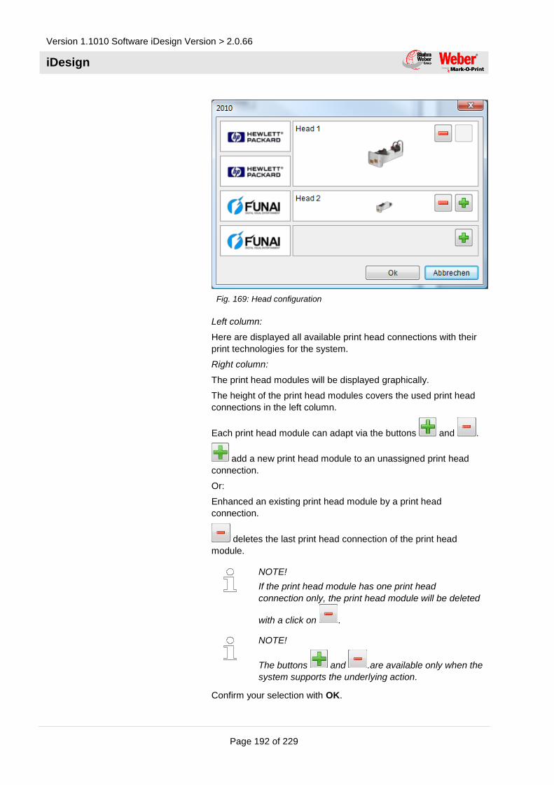
Version 1.1010 Software iDesign Version > 2.0.66
iDesign
Page 192 of 229
Fig. 169: Head configuration
Left column:
Here are displayed all available print head connections with their
print technologies for the system.
Right column:
The print head modules will be displayed graphically.
The height of the print head modules covers the used print head
connections in the left column.
Each print head module can adapt via the buttons and .
add a new print head module to an unassigned print head
connection.
Or:
Enhanced an existing print head module by a print head
connection.
deletes the last print head connection of the print head
module.
NOTE!
If the print head module has one print head
connection only, the print head module will be deleted
with a click on .
NOTE!
The buttons and .are available only when the
system supports the underlying action.
Confirm your selection with OK.

Version 1.109 Software iDesign Version > 2.0.64
iDesign
Page 193 of 229
Master head configuration
This parameter is used to control the Compactline 3.0 with more
than four print heads only. The Compactline 3.0 consist of two
boards, one Master-and one Slave-board. It can set the
corresponding head configuration, i.e. 6 cartridges.
Print technology
The field Print technology listed all supported print technologies
of the print system.
To select a print technology for each channel,
1. Select the tab Device Setup in the submenu System.
2. Set the desired technology in the dropdown menu Print
technology.
NonStopPrinting
In the field NonStopPrinting can be selected whether it should be
print with a NonStopPrinting print head continuously without
downtimes.
To select the NonStopPrinting function,
1. Select the tab Device Setup in the submenu System.
2. Set the desired function in the dropdown menu
NonStopPrinting.
NOTE!
The function can be used for HP and LX print heads.
A special print head is necessary.
HiSpeed
In the field HiSpeed can be selected whether the print system
should print with HiSpeed or not.
HP print heads can reach a maximum speed of 180 m/min at
300x300 dpi, LX print heads reach a maximum speed of 240
m/min.
To select the HiSpeed function,
1. Select the tab Device Setup in the submenu System.
2. Set the desired function in the dropdown menu HiSpeed.
NOTE!
The function can be used for HP and LX print heads. It
is only available in connection with the Pro version.
This function isn’t available in all print systems!

Version 1.1010 Software iDesign Version > 2.0.66
iDesign
Page 194 of 229
Device name
Change the device name of the system. Please see also page 62.
Configuration code
It’s possible to change the system configuration for the iJET and
X-series, i.e. the setting if the controller is a Print, Basic, Advanced
or Pro system.
Please see also page 63.
Update firmware
WARNING!
Data loss effected by update!
It can happen a data loss with an update of the
system software.
Therefore
Perform a backup before every update (see:
"Advanced settings").
1. To update a new print system, click on Settings in the main
menu.
2. Click in the submenu System on the tab Device Setup.
3. Click in the line „Update firmware“ on the icon to start
the update process.
You will guided through the update process depending on
the system.
IP Address
Change the IP address of the system with this function. Please see
also page 68.
Netmask
Change the netmask of the system with this function.
Gateway
Change the Gateway-address of the system with this function.

Version 1.109 Software iDesign Version > 2.0.64
iDesign
Page 195 of 229
CAUTION!
Consult the system administrator for network
settings. Network damages can be caused by
incorrect settings.
Tab Input Output Configuration
All connected in- and outputs of the system can be set with this
function.
A variety of configurations are possible and so the connectors for
output of status messages (OK, Warning, Error), cartridge level
messages (5% low / empty), print ready and print pulse are
possible to use. On the input side signals for heating, spitting, print
direction, upside print, stop and text selection are possible.
The inputs are NPN inputs standard. Can be changed to PNP via
iDesign software.
To set the in- and outputs,
1. Click in the menu Settings on the submenu System.
The submenu System opens.
2. Click on the tab Input Output Configuration

Version 1.1010 Software iDesign Version > 2.0.66
iDesign
Page 196 of 229
Fig. 170: Input Output configuration
Tab Serial interface EIA232
To configure the serial interface EIA232,
1. Click on the button in the main menu.
2. Click in the menu Settings on the submenu System.
3. Click on the tab Serial Interface EIA232.
4. Select baudrate, data bits,parity and number of stop bits.
Fig. 171: Serial interface EIA232

Version 1.109 Software iDesign Version > 2.0.64
iDesign
Page 197 of 229
Tab Special settings
Fig. 172: Special settings
GS1 Group separator
Here you can define whether the GS sign or the FNC1 sign to be
used in a GS1 DataMatrix. Standard is GS.
„Print done“ – message TZ command
Standard is the confirmation of the TZ command in the single print
modus by print start. The confirmation can be timed to print end.
See also „TZ command“ in the Interface description.
Head number – Response after S1 command
This option generates a response of the preselected head number
after sending the S1 command. I.e. K1 at the beginning of the S1
response.
Standby Funktion for X1 Jet
The Standby function for the X1JET can switch on when the On/Off
button is pressed longer than 10 seconds. Standard the Standby
function is switched off for new systems.
Trigger a print repeat with a sensor impulse
Standard the set print repeat is print as long as the sensor signal is
present. As soon as the sensor signal is deactivate, the repeat
stops. If the option is selected, a short impulse is enough to
conduct the print with all repeats.

Version 1.1010 Software iDesign Version > 2.0.66
iDesign
Page 198 of 229
„Print busy“ signal as „Print ready“ signal
The „Print busy“ signal, which is present from print start to print
end, can switched to a short impulse at the print end.
Submenu Logging
Fig. 173: Logging
The messages, which are generated from iDesign and the
commands, which are send from iDesign to the system will be
shown in real time and saved in the Log files menu.
Start
1. To start the real time logging,
– click on the Start/Stop button.
The generated system messages of iDesign are shown in
the upper window.
Stop
2. To deactivate the logging,
– click on the Start/Stop button.
Delete screen
3. To delete the logo screen,
– click on the Clear button.

Version 1.109 Software iDesign Version > 2.0.64
iDesign
Page 199 of 229
Menu Status
The status menu shows information of the system and whose
operating condition, which can call up.
The window is divided in different fields, depending on the print
system. These fields can be selected via the top tabs.
Please see also page 25.

Version 1.1010 Software iDesign Version > 2.0.66
iDesign
Page 200 of 229
iDesign Touch functions
Menu Editor
The print images are created via the Editor menu. The menu
provides the following functions:
Symbol Function Description
Create new print image Empties the editing area to create a new
print image.
Open print image Opens an existing print image. A preview is
displayed.
Save print image Saves the current print image. Requests a
name if none exists.
Save print image as… Saves the current print image under another
name.
Text field Creates a text field to enter static text in the
print image.
Date / Time field Creates a field to enter a date or time in the
print image.
Barcode field Creates a barcode field to add a barcode to
the print image.
Counter field Creates a counter field to enter a counter in
the print image
Variable field Creates a variable field to enter a variable in
the print image.
Graphic Inserts a graphic in the print image.
Delete field A marked field in the print image or a
complete print image is deleted.
Import / Export Import / export all label and logos from / to a
free selectable storage location
Ink consumption
calculator
Determines the number of prints of the
desired label, which can be print with a full
cartridge.
Incremental The selected field can be moved pixel by
pixel.

Version 1.109 Software iDesign Version > 2.0.64
iDesign
Page 201 of 229
Symbol Function Description
Assign a set of
parameters to a text
Assignment of a set of parameters to an
opened print image in the Editor
Rotate field A marked field in the print image is rotated
clockwise in 90° steps.
Undo / Redo Undo and Redo of all edit steps or the
current label
Maximize Maximize the display of the Editor-print
range
Minimize Minimize the display of the Editor-print
range

Version 1.1010 Software iDesign Version > 2.0.66
iDesign
Page 202 of 229
Create print image
A print image may consist of different elements and fields:
Text
Date/Time
Barcode
Counter
Variable
Graphic
Data base
The following chapters describe the insertion and processing of
these elements and fields.
To create a print image, the Editor menu must be called up and the
on-screen keyboard faded in:
1. Select the button in the main menu.
The Editor menu opens.
2. Select the button to fade in the screen keyboard.
The screen keyboard is faded in.
Fig. 174: Editor menu with screen keyboard
NOTE!
Please find further information for the fields from page
83.

Version 1.109 Software iDesign Version > 2.0.64
iDesign
Page 203 of 229
Insert a text field
Static text is inserted in the form of text fields in the print image.
To create a text field,
1. Select the Fehler! Es ist nicht möglich, durch die
Bearbeitung von Feldfunktionen Objekte zu erstellen. button in
the Editor menu.
The editing window opens.
Fig. 175: Edit window text
2. Enter text via the on-screen keyboard.
2. Edit the type format if needed (Printer fonts or Windows fonts).
3. Select OK button.
The text field is inserted into the print image.
1. To position the text field in the print image,
– Position your cursor on the text field and drag it across
the screen to the required position.
or:
– Select the text field and highlight.
– Select the arrow keys and move the text field to the
required position.
A text field inserted in the print image may be edited and changed
at any time:
1. Double click on the text field.
The editing window opens.

Version 1.1010 Software iDesign Version > 2.0.66
iDesign
Page 204 of 229
Graphic text field
Fig. 176: Graphic text field
6. To create a graphic text field, click on the button True Type. All
fonts types of Windows available now.
7. Height and width are adjustable with the red handle.
Fig. 177: Change size of the graphic text field

Version 1.109 Software iDesign Version > 2.0.64
iDesign
Page 205 of 229
Insert a date field
Date and time are embedded in the print image as a date field.
Date fields are not static but dynamic fields; their display format is
defined by variables.
The current date and current time are retrieved from the PC clock.
Optional combinations of variables can be used to configure the
display format. Punctuation marks (e.g. stop, colon, hyphen, space
etc.) can be inserted between the individual codes. ab.cd.gh are
preset.
Pre-dating to, for instance, print a best before date, can be defined
by setting the offset parameters year, month and day.
To create a date field,
1. Select the Fehler! Es ist nicht möglich, durch die
Bearbeitung von Feldfunktionen Objekte zu erstellen.
button in the Editor menu.
The editing window opens.
Fig. 178: Edit window date
2. Select the Format drop down menu and select the Date/Time
format with the scroll bar or accept the default setting.
3. Set a best before date, if required. To do this, select the
year/month/day figures using the arrow keys.
4. If necessary, adjust the font format.
5. Confirm with OK.
The date field is inserted in the print image.
6. To position the date field in the print image,
– Position your cursor on the date field and drag it across the
screen to the required position.
or:
– Select the date field and highlight.
– Select the arrow keys and move the date field to the
required position.
A date field inserted in the print image may be edited and changed
at any time:

Version 1.1010 Software iDesign Version > 2.0.66
iDesign
Page 206 of 229
1. Double click on the date field.
The editing window opens.
Insert a barcode
A barcode is machine-readable “text” comprising parallel lines of
various widths, and gaps.
The information content in the barcode can also be displayed in
writing legible to people in a plain text row directly below the
barcode, If the barcode cannot be read, the information can be
read manually.
The following barcode types are available:
Barcode Type Description Digits
EAN 8
Numerical commercial barcode; used worldwide.
8
EAN 13
Numerical commercial barcode; used worldwide.
13
EAN 128
Numerical commercial logistics code. Variable fields for date, counter and scale as options.
-
Code 2 of 5
Numerical industrial (materials-handling technology) barcode, always
with even digits. (also marked as: 2/5 interleaved, ITF 2/5)
min. 2
DUN 14
Numerical industrial and commercial barcode.
14
UPC A
Same as EAN 13, but 1st digit in special code,
normally set to 0 followed by 11 digit code.
The 13th digit is an automatic test digit. Application: USA/Canada.
13
Code 128
Full ASCII barcode; medical-pharmaceutical technology.
Code 39
Alphanumeric barcode for industry, electronics, pharmaceutical.
-
Data Matrix
A 2D code for the electronics industry and pharmaceutical sector.
-
EAN Data Matrix
A 2D code for the commercial and pharmaceutical sector.
-
QR Code
Quick Response, 2D Barcode specially in Japan
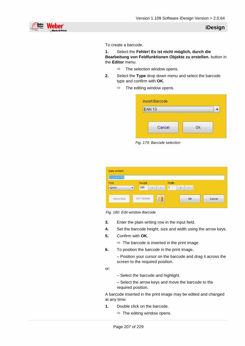
Version 1.109 Software iDesign Version > 2.0.64
iDesign
Page 207 of 229
To create a barcode,
1. Select the Fehler! Es ist nicht möglich, durch die
Bearbeitung von Feldfunktionen Objekte zu erstellen. button in
the Editor menu.
The selection window opens.
2. Select the Type drop down menu and select the barcode
type and confirm with OK.
The editing window opens.
Fig. 179: Barcode selection
Fig. 180: Edit window Barcode
3. Enter the plain writing row in the input field.
4. Set the barcode height, size and width using the arrow keys.
5. Confirm with OK.
The barcode is inserted in the print image.
6. To position the barcode in the print image,
– Position your cursor on the barcode and drag it across the
screen to the required position.
or:
– Select the barcode and highlight.
– Select the arrow keys and move the barcode to the
required position.
A barcode inserted in the print image may be edited and changed
at any time:
1. Double click on the barcode.
The editing window opens.

Version 1.1010 Software iDesign Version > 2.0.66
iDesign
Page 208 of 229
Insert a counter field
The counter is inserted in the print image by means of counter
fields. Counter fields are inserted to print consecutive numbers on
packaging or labels.
At the start of printing, the starting value of the counter appears in
the first print. When reaching the counter end value, counting starts
at the starting value again. If the starting value is smaller than the
end value, counting is downward.
Example 1:
Starting value: 01, end value: 10, step size: 2, repeats: 3
Print: 01, 01, 01, 03, 03, 03, 05, 05, 05....
Example 2:
Starting value: 10, end value: 1, step size 1, repeats: 0
Print: 10, 9, 8, 7....1, 10, 9, 8, 7....
To create a counter field,
1. Click on the Fehler! Es ist nicht möglich, durch die
Bearbeitung von Feldfunktionen Objekte zu erstellen. button in
the Editor menu.
The editing window opens.
Fig. 181: Edit window Counter
2. Select the Start value input field and enter the start value
via the screen keyboard.
3. Select the End value input field and enter the end value via
the screen keyboard.
4. Select the Step width input field and enter the step size via
the screen keyboard.
5. Select the Repeats input field and enter the repeat rate via
the screen keyboard.
6. To print zeros preceding a number as well, select the
checkbox and tick.

Version 1.109 Software iDesign Version > 2.0.64
iDesign
Page 209 of 229
7. If necessary, adjust the font format.
8. Confirm with OK.
The counter field is inserted in the print image.
9. To position the counter field in the print image,
– Position your cursor on the counter field and drag it
across the screen to the required position.
or:
– Select the counter field and highlight.
– Select the arrow keys and move the counter field to the
required position.
A counter field inserted in the print image may be edited and
changed at any time:
1. Double click on the counter field.
The editing window opens.
Insert a variable field
Variables are inserted in the print image through variable fields.
Variable fields are inserted if a print image contains data (e.g.
batch numbers) that change frequently. This can be performed
automatically, shortly before the print image is released for printing.
The variable field is queried before each print image is called up. A
dialogue window appears, requesting the variable value to be
entered. A new text may be entered or the old text retained. It is
possible to enter several variable fields in a text.
Informative text is available as an additional function. This text (e.g.
batch numbers) is displayed at subsequent print requests, to
prevent incorrect entries or mistakes in variable fields in a print
image.
To create a variable field,
1. Click the Fehler! Es ist nicht möglich, durch die
Bearbeitung von Feldfunktionen Objekte zu erstellen. button in
the Editor menu.
The editing window opens.
Fig. 182: Edit window Variable
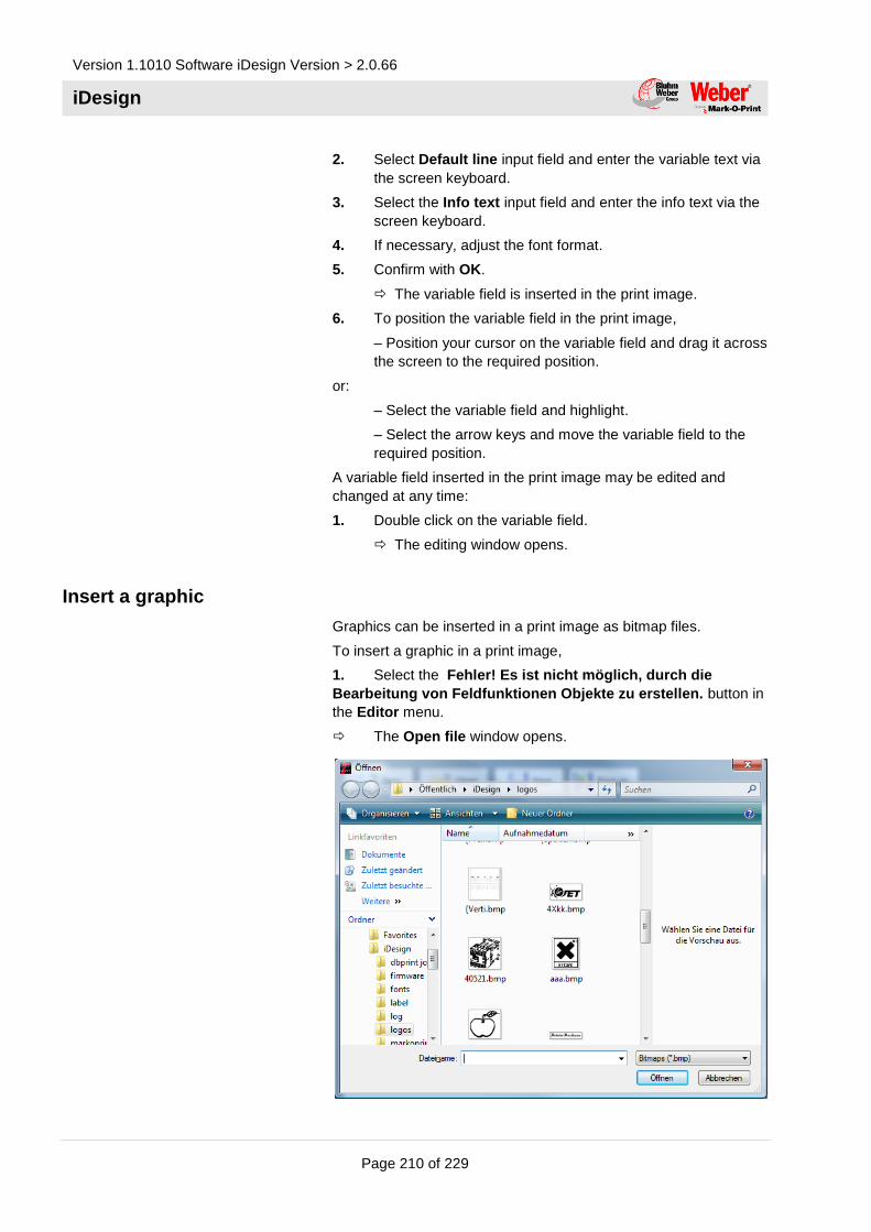
Version 1.1010 Software iDesign Version > 2.0.66
iDesign
Page 210 of 229
2. Select Default line input field and enter the variable text via
the screen keyboard.
3. Select the Info text input field and enter the info text via the
screen keyboard.
4. If necessary, adjust the font format.
5. Confirm with OK.
The variable field is inserted in the print image.
6. To position the variable field in the print image,
– Position your cursor on the variable field and drag it across
the screen to the required position.
or:
– Select the variable field and highlight.
– Select the arrow keys and move the variable field to the
required position.
A variable field inserted in the print image may be edited and
changed at any time:
1. Double click on the variable field.
The editing window opens.
Insert a graphic
Graphics can be inserted in a print image as bitmap files.
To insert a graphic in a print image,
1. Select the Fehler! Es ist nicht möglich, durch die
Bearbeitung von Feldfunktionen Objekte zu erstellen. button in
the Editor menu.
The Open file window opens.

Version 1.109 Software iDesign Version > 2.0.64
iDesign
Page 211 of 229
Fig. 183: Open file
2. Select the drop down menu and select a directory.
3. Select a graphic in the field and highlight.
A preview of the graphic is displayed in the field.
4. To open the graphic,
– Double click the bitmap file.
or:
– Select the bitmap file and highlight.
– Click the button.
The graphic is inserted in the print image.
5. To position the graphic in the print image,
– Position your cursor on the graphic and drag it across the
screen to the required position.
or:
– Select the graphic and highlight.
– Select the arrow keys and move the graphic to the
required position.
Assign a set of parameters to a print image
There is the possibility to assign a pre-saved set of parameters to a
print image and to print them with the saved settings.
NOTE!
The generation and saving of a set of parameters is
described on page 191.
To assign a set of parameters to a print image,
1. Open the desired print image in the editor and touch the
button.
A dialog for text selection opens.

Version 1.1010 Software iDesign Version > 2.0.66
iDesign
Page 212 of 229
Fig. 184: Print parameter set
2. Select the desired parameter set in the drop down menu and
confirm with OK .
3. Save the print image by touching the Save
button.
4. Select the pre-saved print image by touching the Start
button in the main menu.
The print image will be printed with the assigned
parameter set now.
NOTE!
If the parameter values will be changed during
printing, this have no effects for the saved parameter
set of the print image.
Viz. if the print image call up with the Start
button again, it will be print with the saved parameter
set.
Data base
To use the data base function, the data base must be opened (see
also page 115).
An opened data base is identified by this symbol .
A text field for creation will be opened in the editor.
Fig. 185: Text field with open data base
Select the button for the data base .
Select a random column from the data base, over the field name.

Version 1.109 Software iDesign Version > 2.0.64
iDesign
Page 213 of 229
Fig. 186: Field name selection
Confirm after selection and add further fields in the same
procedure.
The field names are place holder in the label now and will be
identified by the line |Field name|.
Fig. 187: Text field
To open a specific row from the data base press the button
by the print start. The information will be insert in the label
automatically..
Edit the font format
1. Select the button in a field’s editing window.
Fig. 188: Edit window
2. Select the Name drop down menu and select the font type
using the scroll bar.

Version 1.1010 Software iDesign Version > 2.0.66
iDesign
Page 214 of 229
3. Use the arrow keys to select the font width.
4. Confirm with OK.
Save print image
To save a print image already created
1. Select the button in the Editor menu.
2. To save the print image under another name, select the
button.
The file dialog opens.
Fig. 189: File dialog
3. Enter the file name in the File name field via the on-screen
keyboard or select the file to be overwritten in the Save file
field.
NOTE!
The file automatically receives a .00I extension.
4. Confirm with OK.
The print image is saved.
Open print image
To open a print image already created,
1. Select the button in the Editor menu.
The file dialog opens.

Version 1.109 Software iDesign Version > 2.0.64
iDesign
Page 215 of 229
Fig. 190: File dialog
2. In In the Open file field, press the print image and highlight.
The print image appears in the Preview window.
3. Confirm with OK.
The print image is opened.

Version 1.1010 Software iDesign Version > 2.0.66
iDesign
Page 216 of 229
Delete print image
1. To delete a print image already created,
– Select the button in the Editor menu.
The file dialog opens.
2. In the Open file field, press the print image and highlight.
The print image appears in the Preview window.
3. Select the button to delete the print image.
4. Confirm with OK.
The print image is deleted.
Menu Setup
The menu Setup includes following submenus:
System
Interface
Database
Directories
Submenu System
To display the System submenu,
1. Select the button in the main menu and click on
the submenu System.
The submenu System opens.

Version 1.109 Software iDesign Version > 2.0.64
iDesign
Page 217 of 229
Fig. 191: Submenu System
Specify start parameter
If the Windows Shell Interface (user interface) is activated, the
program starts automatically and the system shuts down when
closing the program.
This function is active standard.
If the function is deactivated, the program must be started
manually via the desktop; Windows XP will not shut down when the
program is closed.
CAUTION!
Malfunctions due to incorrect Windows system
settings!
The Windows system may malfunction due to
incorrect settings in the print system.
Therefore:
– Settings may only be applied by specialised staff.
To deactivate the Windows Shell Interface, go to the submenu
Settings, to the tab System and General
1. Select the checkbox and untick.

Version 1.1010 Software iDesign Version > 2.0.66
iDesign
Page 218 of 229
Adjust Event log
During printing, all the operating data are captured by the system
and recorded in a log file. This file can be displayed as an event
log. See also page 227.
The data file will be saved in the index iDesign / Log below the
date automatically.
I.e.: 2017-01_01.txt
The data that should be recorded in the log file can be selected.
Type of data Description
No data No data are logged.
Diagnostics All data are logged.
Notes Texts and notes are logged.
Errors Errors arising are logged.
To adjust the event log,
1. Select the Log level drop down menu.
2. Choose the required option from the list and select.
User language
The User language field lists all the installed user languages.
To select a user language, go to the menu Setup, to the submenu
System
1. Select a language.
The user interface is immediately shown in the selected
user language.

Version 1.109 Software iDesign Version > 2.0.64
iDesign
Page 219 of 229
Fig. 192: User language
Counter start value
The start value of a counter must be confirmed with print start or
rather the desired start value can be entered by using a counter
field in a print image with an active function. The last counter value
will be saved by a print stop and continued with a new print start.
Which counter start should be written, can be adapted.
Data type Description
From Label The defined start value in a label will be used
as counter value automatically (standard).
User input The counter start value will be queried without
standard value.
Last value The current counter value will be saved in the
label and used with a new print start.
Query last value The counter start value will be queried from
the user. Der Zählerstartwert wird vom
Benutzer abgefragt. The current counter
value is displayed as default line.
To activate the function,
1. Click on Setup in the main menu and on the submenu
System.
The submenu System opens.
2. Click on the dropdown menu Counter start value.
3. Select the desired option.

Version 1.1010 Software iDesign Version > 2.0.66
iDesign
Page 220 of 229
Check for firmware update
If this function is enabled, the firmware version of an added print
system will be checked whether the firmware is up to date. If this
isn’t the case, the user is informed by a dialog and is guide through
the update process on request.
Print pause after Shutdown
If the system is shut down with an active print, it will not be print
automatically with a restart, the system is in a pause mode. This
prevents an automatic print start after switch-on. The safety
function can disabled.
Disable main window frame
For a higher-level software, in which iDesign Touch should be
embed, the window frame of the main application can switched off.
Keyboard layout
The field keyboard layout list all installed keyboard layouts.
To select a keyboard layout,
1. Click in the menu Settings on the submenu System.
2. Select the desired layout.
The keyboard is shown in the desired keyboard layout
directly.
Store variable fields
This option specifies whether a queried variable field is saved with
print request and will be displayed as default line with a new print
request. This is useful to enter only the data that has actually
changed. Data that hasn’t changes can confirm by the Enter-
button.
User Management
To activate the user management, please proceed as follows:
1. Click in the main menu on the button Settings and the
submenu System.
The submenu System opens.
2. Click on the button and select the
desired user management.
An overview for the performance features and the setup of the
separate user managements can be found from page 139.

Version 1.109 Software iDesign Version > 2.0.64
iDesign
Page 221 of 229
Submenu Interface
If the print system is connected to and controlled by a machine
control point or PC via an external interface, such interface must
be set up.
The following interfaces are available for selection:
Ethernet interface RJ45
Serial interface RS232
Ethernet interface
To set up the Ethernet interface, go to the menu Setup and
submenu Interface
1. Check the box „Enable“.
2. Using the screen keyboard, enter the enabled data port
(standard: 10200) in the activated input field.
Serial interface RS232
To set up the Ethernet interface, go to the menu Setup and
submenu Interface
1. Check the box „Enable“.
2. Select and click on the com port address in the dropdown
menu Com Port.
NOTE!
The selected port address must correspond to the port
address of the Windows interface. By default it is COM1.

Version 1.1010 Software iDesign Version > 2.0.66
iDesign
Page 222 of 229
3. Select and click on the baudrate in the dropdown menu
baudrate.
The serial interface is set up.
NOTE!
The selected baud rate must correspond to the baud
rate of the connected PC!

Version 1.109 Software iDesign Version > 2.0.64
iDesign
Page 223 of 229
Submenu Data base
The data connection can setup in this submenu. The data
connection can i.e. an excel chart or also an ODBC connection to
an external data base. If this connection is setup and opened, it will
be closed after program end and will be automatically re-
established with a restart.
You can change the following settings in submenu Data base:
Open/Close data base
Database settings
1. Press the button in the main menu.
2. Click on the submenu data base.
Fig. 193: Submenu Data base
Select data base
To select / activate a database press the button.

Version 1.1010 Software iDesign Version > 2.0.66
iDesign
Page 224 of 229
Fig. 194: Data source selection
Database from file,
Fig. 195: Open data base
or select ODBC database connection.
Fig. 196: ODBC data base connection
If a data base connection is established, one of the charts must
select for use. An access to multiple charts at once isn’t possible.
You´ll see in iDesign software the database connection tool
In the print operation mode this button is also a search function.
Within label design of iDesign it will change properties.
With pressing the database will closed / disconnected.

Version 1.109 Software iDesign Version > 2.0.64
iDesign
Page 225 of 229
If a database connection is not closed explicitly, iDesign restore it
with a program start automatically.
Search
With the button a line / entry can be triggered. The
search function is always fixed to the previously defined index field.
Buttons allows navigation in the
database. The outer buttons (left) first entry and (right) end of
database. Both middle buttons allows scroll in between the
database entry.
Settings
Calculate MHD offers the possibility for to have an automated
offset function for the date function which is calculated from
defined field of a database. This function takes the actual date and
adds the offset entered in “field name” Therefore the date field will
be added by the value defined in “field name” by days.
There´s a double check possibilty activating the checkbox „User
inquiry“. The generated date can controles and changed by the
operator. If the checkbox is “active”, the option can turnedon or off.
Fig. 197: Calculate the best before date

Version 1.1010 Software iDesign Version > 2.0.66
iDesign
Page 226 of 229
The “Alternativ Layout” field enables download of an alternative
layout from the table. The field name for this can be defined here.
This function is switched on by ticking “active”. The name of the
alternative layout must be stored in the table. If the field is empty,
the Standard Layout remains in use.
Fig. 198: Field Alternativ Layout
Submenu Directories
Im Einstellungsmenü Verzeichnisse hat man die Möglichkeit
existierende Labelverzeichnisse zu registrieren. Registrieren heißt,
dass dieses Unterverzeichnis im Dateiauswahldialog angezeigt
wird.
„Unterverzeichnis einschließen“ bedeutet, dass alle
Unterverzeichnisse eines registrierten Ordners ebenfalls zur
Auswahl angezeigt werden.

Version 1.109 Software iDesign Version > 2.0.64
iDesign
Page 227 of 229
Menu Action log
In the Event log submenu, all printed print images, events and
warnings and alarms that have arisen are listed in chronological
order. The data to be displayed can be selected.
To display the Event log,
1. Select the in the main menu.
The Event log opens.
Fig. 199: Action log

Version 1.1010 Software iDesign Version > 2.0.66
iDesign
Page 228 of 229
Appendix
Directory structure
The iDesign software has the following directory and sub-directories:
[data] Example database
[firmware] Includes firmware files for the coding systems
[fonts] Include fonts
[label] Print images
[local] Include language files.
[logos] Include the logos for the labels.
[settings] Include temporary configuration files.
[terminal] Include saved terminal notes.
[log] Include saved log files.

Version 1.109 Software iDesign Version > 2.0.64
iDesign
Page 229 of 229
Own notes
SKETCH: