Identify and sort panels powerway. See below. Powered ...
50
1 Identify and sort panels by like sizes, fabrics, surface type (tackable vs hard), and NON- POWERED vs POW- ERED. Non-powered panels ship without a powerway. Powered panels include a powerway. See below. Powered panels ship with powerway at- tached. Layout drawing will indicate powered panels with a “V” shaped line through the panel symbol. These panels should be placed accordingly to prevent moving powerways after the fact. The Universal Connec- tor Bracket, or “Porkchop” is used to connect the bottoms of all MWall panels and the tops of all panels of equal height. This same bracket is used with 90, 45 and 120 degree connections.
Transcript of Identify and sort panels powerway. See below. Powered ...

1
Identify and sort panelsby like sizes, fabrics,surface type (tackablevs hard), and NON-POWERED vs POW-ERED. Non-poweredpanels ship without apowerway. Poweredpanels include apowerway. See below.
Powered panels shipwith powerway at-tached. Layout drawingwill indicate poweredpanels with a “V”shaped line through thepanel symbol. Thesepanels should be placedaccordingly to preventmoving powerways afterthe fact.
The Universal Connec-tor Bracket, or“Porkchop” is used toconnect the bottoms ofall MWall panels andthe tops of all panels ofequal height. Thissame bracket is usedwith 90, 45 and 120degree connections.

2
It is important to planfor the connection ofFUTURE panels whileinstalling currentpanel. Start at a 2-wayconnection. Attachporkchop to the bottomof Panel A as shown forthe 90 degree corner.Note that angled side isflush with panel face.
On opposite end ofPanel A, attach aPorkchop as shown forthe next adjacent panel,in this case, a straightconnection. Use ta-pered 1/4-20 screwsincluded. Screws use a3/16 hex drive.
If cables will be runningthrough to adjacentpanels in the future, theperforated metal knock-out on the raceway endmust be removed. Firmpush or strike a screw-driver into the middle ofthe knockout as shown.
Angled SideFlush with PanelFace

3
Once the top of theknockout has brokenaway, rotate knockoutout back and forth toremove.
Panel B is to be in-stalled 90 degrees toPanel A. On this panel,install a Pin in the out-side corner of the race-way frame.
Install a Pin in the out-side corner of the race-way frame of Panel Bon the side which willabut Panel A.

4
Prior to installing PanelB, attach Porkchop topanel other end ofPanel B for installationof future panel. Alwaysthink of the next adja-cent panel and planaccordingly.
Prior to installing PanelB, be sure all glidesare minimized.
Insert Pin on Panel Bdown into Porkchop onPanel A as shown.
AttachPorkchop onopposite endof Panel B asshown

5
Be sure Panel B isseated flush on top ofPorkchop on Panel A.
At TOP of Panels A andB, attach a Porkchop asshown. Porkchopshould MIRRORporkchop on the bottomof Panel A.
Use drill driver set onmedium torque with a 3/16 hex drive to attachporkchops to the top ofPanel A and B with 1/4-20 tapered screws sup-plied.
6
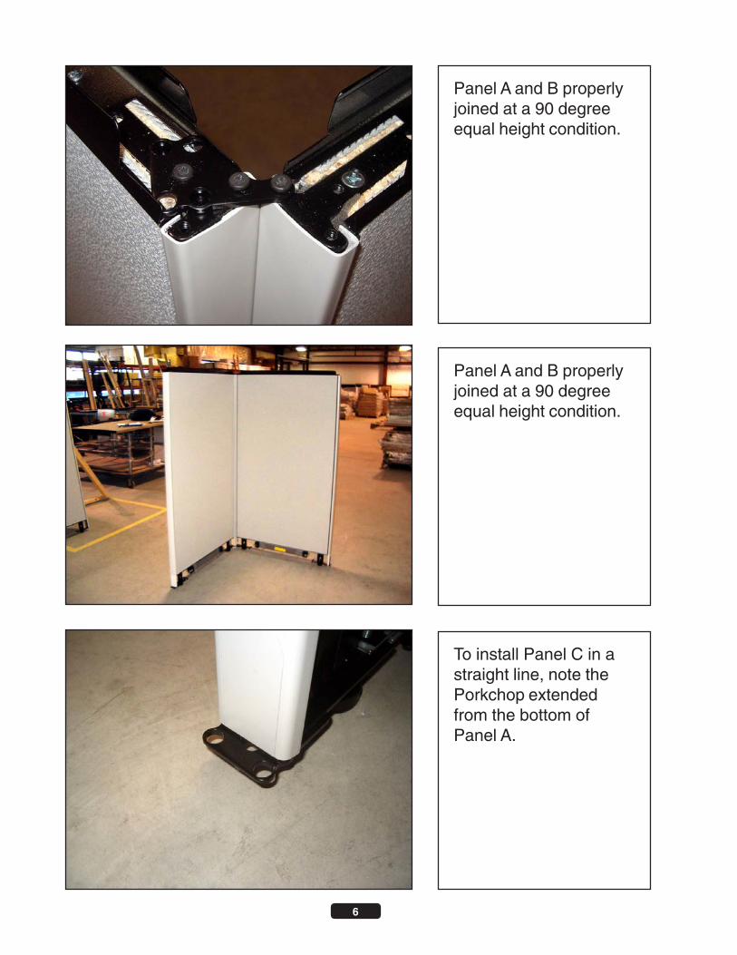
Panel A and B properlyjoined at a 90 degreeequal height condition.
Panel A and B properlyjoined at a 90 degreeequal height condition.
To install Panel C in astraight line, note thePorkchop extendedfrom the bottom ofPanel A.

7
Install 2 Pins at thebottom of Panel C onthe end that is to abutPanel B. NOTE, BESURE TO ATTACH APORKCHOP to theother end of this Panelfor the next panel in line.
Insert Pins on Panel Cdown into Porkchop onPanel B as shown.
Be sure Panel C isseated flush on top ofPorkchop on Panel B.

8
At TOP of Panels B andC, attach a Porkchop asshown. Porkchopshould MIRRORporkchop on the bottomof Panel B.
Use drill driver set onmedium torque with a 3/16 hex drive to attachporkchops to the top ofPanel B and C with 1/4-20 tapered screws sup-plied.
Panel D, low panel, willabut Panel A in astraight line. Configurethe bottom of panels Dand A as indicated inthe straight connectionshown for Panels B andC. See Previous. At-tach Universal StraightHiLo bracket to the topof Panel D as shown.

9
Mark holes on UniversalStraight HiLo (USH) onPanel A endcap and drillTHROUGH Endcap,Through Steel HangerFrame with 3/16 drill bit.NOTE, you may preferto mark holes and movePanel D prior to drilling.
Using screws suppliedlabeled “For StraightHiLo Connections”,screw though USH intoPanel A (High Panel) asshown. Be careful notto over tighten andcrush endcap.
Shown is the bottom ofPanel C, which waspreviously installed in astraight line abuttingPanel B. At the oppo-site end of the straightconnection, a Porkchopwas installed for a panelto be installed at 90degrees.

10
Panel E is configuredsuch that a Porkchop isattached for connectingPanel F in a 3-way con-nection. A Pin is in-stalled adjacent to thePorkchop as shown forconnection to Panel C.
Insert Pin on Panel Edown into Porkchop onPanel C as shown.
Be sure Panel E isseated flush on top ofPorkchop on Panel C.Note the Porkchop onPanel E is configured toconnect Panel F.
Pin Installedadjacent toPorkchop.

11
At TOP of Panels C (onright) and E (on left),attach a Porkchop asshown. Porkchopshould MIRRORporkchop on the bottomof Panel C.
With Panel F configuredwith a Pin for a 90 de-gree connection, InsertPin on Panel F downinto Porkchop on PanelE as shown.
Be sure Panel F isseated flush on top ofPorkchop on Panel E.
Panel F
Panel E
Panel C

12
At TOP of Panels E (inMiddle) and F (on Left),attach a Porkchop asshown. Porkchopshould MIRRORporkchop on the bottomof Panel E.
Attach Panel G to otherside of Panel E in astraight connection NOTshown here. Panel H isa low panel installed 90degrees to Panel G. Asshown, set up bottom ofLEFT HAND PANELwith a Porkchop at 90degrees. Panel H is setup with a Pin.
Left hand panel (PanelG) is indicated whenstanding on the inside ofthe 90 degree connec-tion, opposite of theview shown here. LEFTHAND PANEL MUSTALWAYS GET THEPORKCHOP whenconnecting a 90 degreeHilo.
Panel G(Left)
Panel H(Right)
Panel HLow(Right)
Panel GHigh(Left)

13
Universal Corner HiLobracket consists of 2brackets. A smallbracket with two holes(SB2) and a largerbracket with one hole(LB1), bolted togetherwith a 2 1/4 hex bolt anda nut.
With nut barelythreaded on bolt, insertteeth on SB2 into theright hand panel andengage down ontohanger frame slotsabout 3 inches from thetop of the low panel.Insert drilldriver into boltand hold SB2 downonto right panel.
Holding SB2 down,engage teeth on LB1into left hand framegoing UP. Slowlytighten bolt so that pan-els draw together. Allteeth must be engaged.NOTE, it is easier toengage LB1 if panelsare temporarily set atless than 90 degrees.
Panel HLow(Right)
Panel GHigh(Left)
Panel HLow(Right)
Panel GHigh(Left)
Tighten untilbolt head isslightly belowtop ofbracket. DONOT OVERTIGHTEN.

14
Install end filler at everyend of panel run withtwo taper bolts. Theend of run filler is alsoused at the top of astraight HiLo connec-tion.
IMPORTANT - set drillon LOW TORQUE andgently tighten bolts toavoid breaking endfillers.
Corner Fillers, or “TearDrops”, are used to trimareas next to Porkchopsat a 90 degree angle.

15
IMPORTANT - set drillon LOW TORQUE andgently tighten bolts toavoid breaking endfillers.
Outlets are markedcircuits 1-4. The layoutdrawing will indicatewhich outlet goes whereper the design. NOTE -In some locations, ALLELECTRICAL COMPO-NENTS must be in-stalled by a licencedelectrician.
Install Duplex outlets byaligning the outlet inter-face with the powerwayinterface as shown.Slide outlet to the left onthe left side, or to theright on the right side,until fully engaged onpowerway as shown.Outlet cannot be in-stalled upside-down.

16
Using screws providedfor “Outlets”, screwoutlet to powerway asshown. Only one screw,top or bottom, is re-quired. NOTE - OutletsMUST be screwed toPowerways.
Outlets are markedcircuits 1-4. The layoutdrawing will indicatewhich outlet goes whereper the design.
Install Jumpers as indi-cated WITH ARROWSon JUMPER modularend pointing UP asshown. Engage jumperfully onto powerway inone of the 2 end loca-tions. Safety Clip MUSTBE fully engaged overClip Ramp to be fullyinstalled.
“Up” Arrow
Clip Ramp
SafetyClip

17
Panel to panel jumpersconnect two panels thatare adjacent at a 90 or astraight connection. 18inch is for straights only.21 inch can be used onboth. If jumping acrossa 3-way or 4-way, an“extended” jumper isneeded.
Pass Through cablesare metal and engagepowerway in the samemanner as panel topanel. Engage jumperfully onto powerway inone of the 2 end loca-tions. Safety Clip MUSTBE fully engaged overClip Ramp to be fullyinstalled.
Pass through cables“pass through” non-powered panels.Specify the jumper thatmatches the length ofpanel to be passedthrough. IMPORTANT -PANELS CONNECTEDELECTRICALLY MUSTBE CONNECTED ME-CHANICALLY.

18
Base in-feeds are in-stalled at unused du-plex outlet locations.ONLY ONE IN-FEEDcan be used on anyconnected run ofpowerways and jump-ers. BREAK powerbetween runs if morethan one feed isneeded.
Pass end of base feedTHROUGH Base Coverat desired outlet loca-tion. A licenced electri-cian must connect thisend of the feed to build-ing power. NOTE - Insome locations, ALLELECTRICAL COMPO-NENTS must be in-stalled by an electrician.
Install other end of feedas you would an outlet.

19
Screw feed to powerwayas shown using screwsprovided labeled for“Outlets”.
Slide base cover downlength of feed until out-let bezel lines up withoutlet hole.
Rest bottom of basecover on spring clipssuch that clip “barb”protrudes up into reliefhole at the bottom out-side corners of the basecover.

20
Keeping bottom of baseon spring clip, rotate topof cover up “under” lip ofraceway frame asshown and snap flushwith panel face. Basewill need to be forced“down” under lip, de-pressing the spring clipsbelow.
Install duplex outletcovers in unused duplexoutlet holes.
To remove Duplex Out-let Covers, Base Covermust be fully removed.

21
Installed base coverwith outlet and duplexoutlet cover.
To install topcaps adja-cent to straight hilos, theperforated knockoutmust be removed at theend of the topcap whichwill abut the Hilobracket. Using handtool, GENTLY twistknockout free.
Install topcap with theknocked out end abut-ting the hilo bracket.

22
Place topcap overtopcap retainer andgently push down untiltopcap is seated prop-erly on Porkchops.NOTE - topcap shouldbe centered on panelsuch that screw tops arehidden from view.
DO NOT bang topcapsdown. Doing so coulddent caps. If cap is tooloose, spread topcapretainer wings slightlyand reinstall.
Properly installed panelsshould be LEVELED byadjusting glides at bot-tom of panels. UseFlatbar to raise panelsslightly and turn glidesby hand. Be sure tosnug all floating glidesdown. Carpet grippersare supplied and maybe used if desired.

23
Insert Right Hand Flip-per Door Shelf End intoa right hand hangerframe slightly above thelevel of a panel topcap.
Insert shelf end intoframe and down untilfirmly seated on hangerframe. Anti-dislodgeCam should rotate backas shelf end is inserted.
Once end is firmlyseated on frame, rotatecam into hanger frameso back edge of cam isparallel to panel face.To remove shelf end,rotate cam back out andlift end. Repeat thisprocedure for left endsand Mid Height ShelfEnds.
Anti-DislodgeCam
Rotate Caminto hangerframe so thisedge is vertical.

24
Hold shelf pan betweenshelf ends and lowerover nuts on shelf end.This may require turningnuts out to loosenslightly. BE CAREFULNOT TO SCRATCHpaint on shelf ends asyou insert and lowershelf.
Shelf pan has two slotpatterns on end. Useslot pattern as show toproperly position shelf.
Lock slot should bepositioned at front onbottom shelf pan.

25
Tighten nut down tosecure shelf. NOTE -Failure to tighten nutscan result in seriousinjury.
Install top shelf pan inthe same way, with thehole pattern for mount-ing a flipper door at thefront as shown.
NOTE - Top shelf andbottom shelf ARE THESAME PART mountedin opposite directions.

26
NOTE - Lock slot facestowards panel on topshelf.
Rest flipper door faceassembly on top shelfwith gear track hingesoriented as shown.
Align holes on geartrack hinges with holeson front of shelf pan andattach with screws pro-vided labeled “FlipperDoors”.

27
Open and close door afew times. If required,door can be adjusted byloosening attachmentscrews and sliding leftor right.
Keys are attached toinside of door face.Remove key and testlock.
Mid height shelves in-stall in the same man-ner as flipper door units.

28
Tasklight brackets mustbe assembled totasklights prior to instal-lation. Insert hook onbracket into slot on light,align hole with hole onlight.
Hold light up under shelfpan. Bend light brack-ets to engage forwardand rear edge flanges ofshelf pan. Be sure eachend of the brackets isfirmly seated. Failure todo so could result ininjury.
With screws provided,attach bracket to light.Be sure not to over-tighten screws. Repeatprocedure on other sideof light.

29
Teeth on bracket insertUP into hanger frame.Insert hook tooth atbottom of bracket intohanger frame at appro-priate height and rotatebracket up into a verticalposition.
Countertop brackets arehanded. Eachcountertop requires atleast two pairs of brack-ets.
Mount top of bracketflush with top of topcap.Bracket will need to belightly tapped to engageupwards fully and toprevent bracket fromfalling before installingtop.

30
Align countertop oncenter of panel. Withscrews provided labeledfor “Worksurfaces”,attach bracket toworksurface. Use atleast 2 screws perbracket.
Shared cantilevers areused to support panelhung worksurfaces at aseam between twopanels. Insert “hook”tooth up into hangerframe at the appropriateheight.
Secure 1 screw on eachside of panel first tostabilize top, then com-plete attachment withremaining holes, alter-nating from one side ofpanel to the next.

31
Rotate cantilever downinto hanger frame andengage down into slots1/4 inch.
Cantilevers should behung between 28 and29 inches to achieveindustry standardworksurface height andmatch structural pedes-tal heights.
Push down oncantlilever and makesure cantilever is fullyengaged. NOTE - fail-ure to engage cantileverproperly can lead toinjury.
32
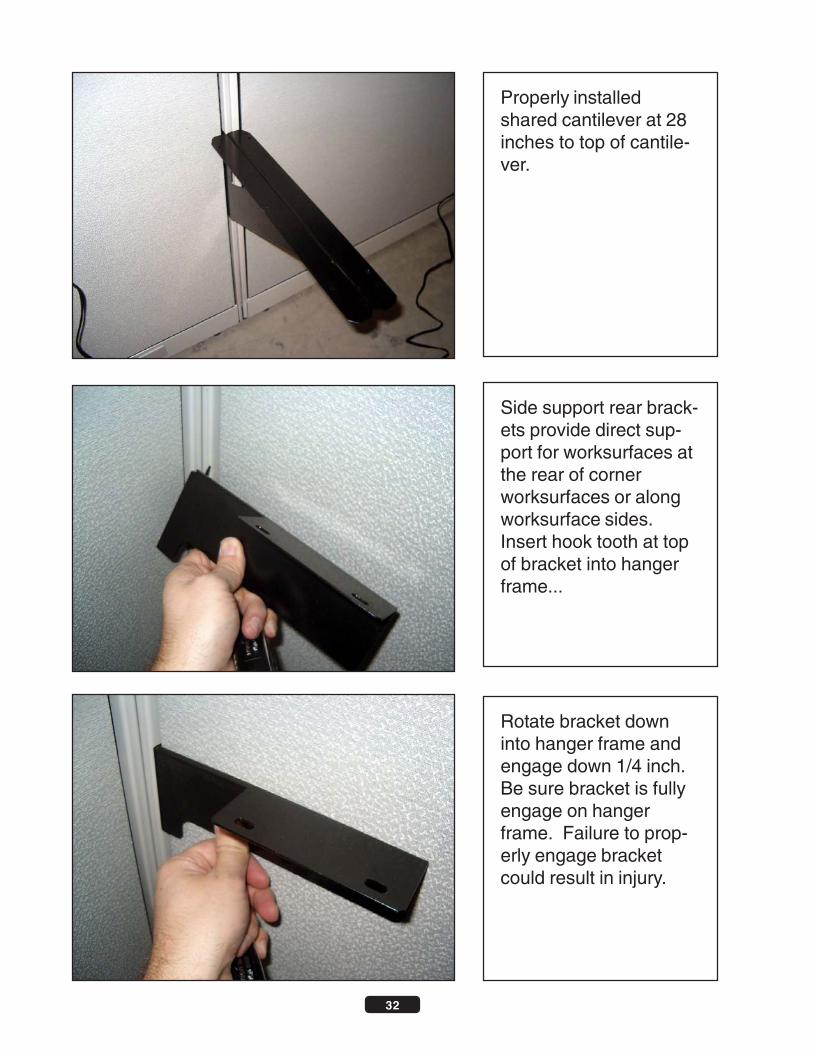
Properly installedshared cantilever at 28inches to top of cantile-ver.
Rotate bracket downinto hanger frame andengage down 1/4 inch.Be sure bracket is fullyengage on hangerframe. Failure to prop-erly engage bracketcould result in injury.
Side support rear brack-ets provide direct sup-port for worksurfaces atthe rear of cornerworksurfaces or alongworksurface sides.Insert hook tooth at topof bracket into hangerframe...

33
Structural pedestalsprovide support forworksurfaces. Screwingpedestals in requiresremoving top file draweror top two box drawers.
On the right side of thepedestal, push leverdown and hold...
To remove pedestaldrawers, pull drawersout completely. Notethe black lever ondrawer stop mecha-nism...

34
On the left side of thepedestal, push lever upand hold. While leversare engaged, pulldrawer out clear of ballbearing slides.
Turn ped over on backand adjust glides ac-cordingly to achieve thecorrect pedestal height.
Pedestals must be setat same height FROMTOP OF PANEL ascantilevers. Measurecantilever height fromtop of panel, then com-pare to pedestalheight...

35
Turn pedestal over anddouble check heights ofall support elements toensure thatworksurfaces will belevel.
Seams betweenworksurfaces should bealigned with panelseams.
Rest worksurfaces ontop of worksurface sup-ports such that edgesare 1/4 inch from panelface and that cornersare aligned on the cen-ter of panel corners...
1/4 inch gap
Corner cen-teredon panelseams

36
Worksurface should“touch” at seams andseams should bealigned with panelseams.
Install Flatplates atseams betweenworksurfaces in front ofshared cantilevers.
While holdingworksurfaces in placeand maintaining align-ment, screwworksurfaces to cantile-vers with screws pro-vided labeled “ForWorksurfaces”. Use 2screws for regula canti-levers and 4 screws forshared cantilevers.
Worksurfacesshould touch
AlignWorksurfaceseam withpanel seam

37
Align pedestal flush withfront of worksurface andscrew to worksurfacewith screws labeled “Forworksurfaces”. Use atleast 2 screws at thefront of pedestal. Forbest results, use screwsat all 4 corners of ped-estal.
Push drawer in to face,then open fully andclose to ensure properslide alignment. IT ISNOT NECESSARY toactuate levers ondrawer stops while rein-serting drawers. NOTE- BE SURE TO TESTLOCK ON PEDESTALSAND adjust as needed.
To replace drawers,push all ball bearingslides into pedestal BUTKEEP INNER BALLBEARING CARRIAGEpulled forward to front ofslide. Carefully aligntrack on drawer boxeswith inner slide carriageand slowly insertdrawer...
Push outerslide backand keep innerslide forward

38
Install all grommetcovers where needed.
Insert tackboard in anddown. Be sure eachside if firmly seated inhanger frame.
Install tackboards byaligning tackboardbrackets with hangerframe slots approximate1 inch aboveworksurfaces. Be suretasklight cord is behindtackboard.

39
3 inch Tasklight cordmanagers can be usedabove tackboards tomanage tasklight cords.Longer tasklight cordmanagers are availableif no tackboard is beingused. Tuck cord intomanager and insertmanager into hangerframe and push down.
2-way base racewayshroud covers cablesrunning in base racewayat 90 degree corners.Be sure gates are fullyseated on racewayframe. Align cover withcorner...
Workstation with com-pleted components.

40
Wrap cover around gatelegs and snap intoplace.
3-way base racewayshroud covers cablesrunning in base racewayat 90 degree 3-waycorners. Be sure gatesare fully seated on race-way frame. Align coverwith gap between pan-els...
Be sure cover is seateddown on raceway frameand fully engaged overgate legs.

41
Wrap cover around gatelegs and snap intoplace.
To install 2-way equalheight post filler, raisegates on both panels upto access the insideTOP of the racewayframe....
Be sure cover is seateddown on raceway frameand fully engaged overgate legs.

42
Place 2-way bottombracket (PF-12) ONTOP of raceway frameas shown....
Re-seat gates on bothpanels down over baseraceway frame.
Using panel standardporkchop bolts, at-tached bracket to race-way frame.

43
At top of frame, removetopcaps and any teardrops previously in-stalled.
Using standardporkchop bolts, attachtop bracket to frames.NOTE - DO NOT OVERTIGHTEN.
Align 2-way top bracket(PF-3) with outsideteardrop holes at top ofpanels...

44
Align 2-way Post Fillerwith corner.
Rotate post filler upUNDER top bracket andalign holes on post fillerwith holes on topbracket.
Rest 2-way post fillerON TOP OF receivingflanges on bottombracket as shown...

45
Using supplied #6 sheetmetal screws, screwdown through topbacket into post filler.NOTE - DO NOT tightenscrews fully. Leaveapprox 1/8 inch of screwout for next step...
Align “slots” on topcapretainer with screwsheads and square re-tainer to post filler face.
Insert post filler TopcapRetainer, (PF-15) UN-DER screw heads fromprevious step as shown.
46
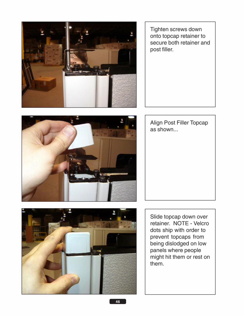
Tighten screws downonto topcap retainer tosecure both retainer andpost filler.
Slide topcap down overretainer. NOTE - Velcrodots ship with order toprevent topcaps frombeing dislodged on lowpanels where peoplemight hit them or rest onthem.
Align Post Filler Topcapas shown...

47
Completed installedPost Filler. NOTE - 2-way post filler sitsslightly recessed incorner as shown. FOL-LOW SAME procedurefor 3-way post fillers.However, 3-way fillersare designed to sitFLUSH with panelfaces.
Install “step” bracket(PF-1) on top of postfiller top bracket suchthat screws hold Stepdown and approximately1/16 inch back from topbracket edge as shown.Tighten screws to holddown Step and securepost filler.
To install INLINEpowerpole on either a 3-way equal height or 2-way equal height postfiller (shown), removetopcap and previouslyinstalled retainer if appli-cable. Loosensheetmetal screws hold-ing post filler approx 1/8inch.
STEP bracketshould sit backapprox 1/16fromtop bracketedge

48
Align inline pole withStep bracket.....
1 3/4 x 1 3/4 hole willneed to be cut in ceilingtile PLUMB with the topof the post filler. Polewill terminate aboveceiling. A shroud isshipped with every polewhich magneticall at-taches to pole at ceilingheight to trim hole.
Slide pole up throughhole cut in ceiling andthen down ON TOP OFStep bracket such thatbracket retains pole andprevents lateral move-ment.

49
Knockout perforatedend of adjacent topcapand install such thattopcap slides OVERextended portion of poleas shown. NOTE -Spreading the topcapretainer on the adjacentpanel will ensure thatthe topcap firmly holdspole down.
Install pole cover bysliding up into ceilinghole and snapping intoplace on pole.
Be sure adjacent topcapis firmly seated to holdpole down.
50
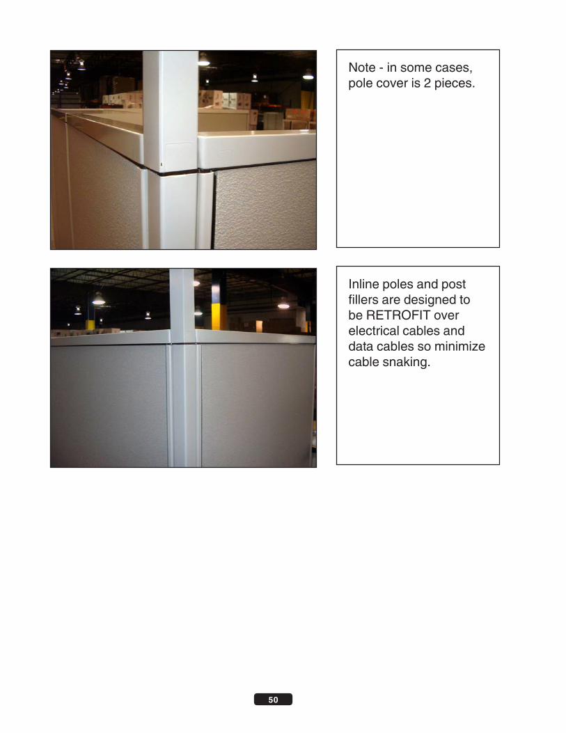
Note - in some cases,pole cover is 2 pieces.
Inline poles and postfillers are designed tobe RETROFIT overelectrical cables anddata cables so minimizecable snaking.