IDAHO TRANSPORTATION...
118
January 2014
-
Upload
truongtuyen -
Category
Documents
-
view
215 -
download
1
Transcript of IDAHO TRANSPORTATION...

January 2014

IDAHO TRANSPORTATION DEPARTMENT
BRIDGE ASSET MANAGEMENT SECTION
STRUCTURE INVENTORY AND APPRAISAL
CODING GUIDE
January 2014

TABLE OF CONTENTS Federal Structure Inventory and Appraisal Items Item Name Page
Introduction…………………………………………………………………………………………………………………………………1 Definition of Terms………………………………………………………………………………………………………………2 Instructions for Coding SIA Sheets………………………………………………………………………5 Sufficiency Rating…………………………………………………………………………………………………………………8
1 State Code………………………………………………………………………………………………………………………………………8 2 District……………………………………………………………………………………………………………………………………………8 3 County…………………………………………………………………………………………………………………………………………………9 4 Place Code………………………………………………………………………………………………………………………………………9 5 Inventory Route………………………………………………………………………………………………………………………13 6 Features Intersected…………………………………………………………………………………………………………16 7 Facility Carried By Structure…………………………………………………………………………………16 8 Bridge Number……………………………………………………………………………………………………………………………16 9 Location…………………………………………………………………………………………………………………………………………17 10 Inventory Route, Minimum Vertical Clearance……………………………………………17 11 Milepoint………………………………………………………………………………………………………………………………………17 12 Base Highway Network…………………………………………………………………………………………………………18 13 LRS Inventory Route……………………………………………………………………………………………………………18 14 Not Used 15 Not Used 16 Latitude…………………………………………………………………………………………………………………………………………19 17 Longitude………………………………………………………………………………………………………………………………………19 18 Not Used 19 Bypass, Detour Length………………………………………………………………………………………………………19 20 Toll……………………………………………………………………………………………………………………………………………………20 21 Maintenance Responsibility…………………………………………………………………………………………21 22 Owner…………………………………………………………………………………………………………………………………………………21 23 Not Used 24 Not Used 25 Not Used 26 Functional Classification……………………………………………………………………………………………22 27 Year Built……………………………………………………………………………………………………………………………………22 28 Lanes On and Under the Structure…………………………………………………………………………23 29 Average Daily Traffic………………………………………………………………………………………………………24 30 Year of Average Daily Traffic…………………………………………………………………………………24 31 Design Load…………………………………………………………………………………………………………………………………24 32 Approach Roadway Width……………………………………………………………………………………………………25 33 Bridge Median……………………………………………………………………………………………………………………………27 34 Skew……………………………………………………………………………………………………………………………………………………28 35 Structure Flared……………………………………………………………………………………………………………………28 36 Traffic Safety Features…………………………………………………………………………………………………28 37 Historical Significance…………………………………………………………………………………………………30 38 Navigation Control………………………………………………………………………………………………………………31 39 Navigation Vertical Clearance…………………………………………………………………………………31 40 Navigation Horizontal Clearance……………………………………………………………………………32 41 Structure Status, Posted, or Closed to Traffic…………………………………32 42 Type of Service………………………………………………………………………………………………………………………33
II

Item Name Page 43 Structure Type, Main…………………………………………………………………………………………………………34 44 Structure Type, Approach Spans………………………………………………………………………………35 45 Number of Spans In Main Unit……………………………………………………………………………………35 46 Number of Approach Spans………………………………………………………………………………………………36 47 Inventory Route, Total Horizontal Clearance……………………………………………36 48 Length of Maximum Span……………………………………………………………………………………………………37 49 Structure Length……………………………………………………………………………………………………………………38 50 Curb or Sidewalk Widths…………………………………………………………………………………………………40 51 Bridge Roadway Width, Curb To Curb……………………………………………………………………42 52 Deck Width, Out To Out……………………………………………………………………………………………………43 53 Minimum Vertical Clearance Over Bridge Roadway……………………………………43 54 Minimum Vertical Underclearance……………………………………………………………………………43 55 Minimum Lateral Underclearance on Right………………………………………………………45 56 Minimum Lateral Underclearance on Left…………………………………………………………46 57 Not Use Condition Ratings – General Information………………………………………………………47 58 Deck……………………………………………………………………………………………………………………………………………………49 59 Superstructure…………………………………………………………………………………………………………………………52 60 Substructure………………………………………………………………………………………………………………………………54 61 Channel and Channel Protection………………………………………………………………………………56 62 Culverts…………………………………………………………………………………………………………………………………………57 63 Method used to determine Operating Rating…………………………………………………59 64 Operating Rating……………………………………………………………………………………………………………………59 65 Method used to determine Inventory Rating…………………………………………………60 66 Inventory Rating……………………………………………………………………………………………………………………61 Appraisal – General Information……………………………………………………………………………63 67 Structural Evaluation………………………………………………………………………………………………………65 68 Deck Geometry……………………………………………………………………………………………………………………………67 69 Underclearances Vertical and Horizontal………………………………………………………71 70 Bridge Posting…………………………………………………………………………………………………………………………74 71 Waterway Adequacy…………………………………………………………………………………………………………………75 72 Approach Roadway Alignment…………………………………………………………………………………………77 73 Not Used 74 Not Used 75 Type of Work………………………………………………………………………………………………………………………………78 76 Length of Structure Improvement……………………………………………………………………………79 77 Not Used 78 Not Used 79 Not Used 80 Not Used 81 Not Used 82 Not Used 83 Not Used 84 Not Used 85 Not Used 86 Not Used 87 Not Used 88 Not Used 89 Not Used 90 Inspection Date………………………………………………………………………………………………………………………82 91 Designated Inspection Frequency……………………………………………………………………………82
III

Item Name Page 92 Critical Feature Inspections……………………………………………………………………………………83 93 Critical Feature Inspection Date…………………………………………………………………………83 94 Bridge Improvement Cost…………………………………………………………………………………………………84 95 Roadway Improvement Cost………………………………………………………………………………………………85 96 Total Project Cost………………………………………………………………………………………………………………85 97 Year of Improvement Cost Estimate………………………………………………………………………85 98 Border Bridge……………………………………………………………………………………………………………………………85 99 Border Bridge Structure Number………………………………………………………………………………86 100 STRAHNET Highway Designation……………………………………………………………………………………86 101 Parallel Structure Designation………………………………………………………………………………87 102 Direction of Traffic…………………………………………………………………………………………………………88 103 Temporary Structure Designation……………………………………………………………………………88 104 Highway System of the Inventory Route……………………………………………………………89 105 Federal Lands Highway………………………………………………………………………………………………………89 106 Year Reconstructed………………………………………………………………………………………………………………90 107 Deck Structure Type……………………………………………………………………………………………………………90 108 Wearing Surface/Protective System………………………………………………………………………91 109 Average Daily Truck Traffic………………………………………………………………………………………92 110 Designated National Network………………………………………………………………………………………92 111 Pier or Abutment Protection (For Navigation)…………………………………………94 112 NBIS Bridge Length………………………………………………………………………………………………………………94 113 Scour Critical Bridges……………………………………………………………………………………………………96 114 Future Average Daily Traffic……………………………………………………………………………………98 115 Year of Future Average Daily Traffic………………………………………………………………99 116 Minimum Navigation Vertical Clearance (Lift)…………………………………………99
State Structure Inventory And Appraisal Items
Name Page Special Inspections – UBIT and Confined Space………………………………………………… 83 Agency Structure ID Number…………………………………………………………………………………………………… 100 Structure Name…………………………………………………………………………………………………………………………………… 100 Segment Code for the Inventory Route………………………………………………………………………… 102 Segment Code Under………………………………………………………………………………………………………………………… 102 Load Rating Analysis…………………………………………………………………………………………………………………… 103 Recommended & Actual Bridge Load Posting……………………………………………………………… 103 Recommended & Actual Bridge Height Posting………………………………………………………… 103 Actual Bridge Width Posting………………………………………………………………………………………………… 104 Wearing Surface Depth for Dead Load…………………………………………………………………………… 104 Load Analysis Status…………………………………………………………………………………………………………………… 104 Administrative Jurisdiction………………………………………………………………………………………………… 105 Bridge Drawing Number………………………………………………………………………………………………………………… 111 Project Key Number………………………………………………………………………………………………………………………… 111 Equipment Required………………………………………………………………………………………………………………………… 111 Inspection Area………………………………………………………………………………………………………………………………… 111
IV
INTRODUCTION
This 2014 edition of the IDAHO BRIDGE INSPECTION CODING GUIDE incorporates a few changes and corrections from our previous issues of the coding guide. The Structure Inventory and Appraisal portion of this coding guide is based directly on the Federal Highway Administration’s RECORDING AND CODING GUIDE FOR THE STRUCTURE INVENTORY AND APPRAISAL OF THE NATION’S BRIDGES, December 1995. The AASHTO MANUAL FOR BRIDGE EVALUATION (MBE), Second Edition 2011 with 2013 Interims addresses requirements for record-keeping, inspection material testing, load rating and posting of bridges. The IDAHO MANUAL FOR BRIDGE EVALUATION (IMBE) 2014 Edition is written as a supplement to the MBE, and presents practices and procedures that are specific to ITD. The BRIDGE INSPECTOR’S REFERENCE MANUAL (BIRM), 2012 Edition discusses inspection procedures and analysis of a structure. Other reporting requirements and qualifications of personnel appear in the National Bridge Inspection Standards (23 CFR650.3). These publications are valuable supplements to this guide and it is highly recommended that inspectors have each of them for reference.

DEFINITION OF TERMS For clarity, the definitions of a few terms used in the Guide are provided below. (a) Bridge. The National Bridge Inspection Standards published in the Code of Federal Regulations (23 CFR 650.3) give the following definition:
A structure, including supports, erected over a depression or an obstruction, such as water, a highway, or a railway, having track or passageway for carrying traffic or other moving loads, and having an opening measured along the center of the roadway of more than 20 feet (6.1 meters) between undercopings of abutments or spring lines of arches, or extreme ends of the openings for multiple boxes; it may include multiple pipes where the clear distance between openings is less than half of the smaller contiguous opening.
(b) Culvert. A structure designed hydraulically to take advantage of submergence to increase hydraulic capacity. Culverts, as distinguished from bridges, are usually covered with embankment and are composed of structural material around the entire perimeter. (c) Inventory Route. The route for which the applicable inventory data is to be recorded. Generally, inventories are made from West to East and South to North. (d) National Bridge Inventory (NBI). The aggregation of structure inventory and appraisal data collected to fulfill the requirements of the National Bridge Inspection Standards (NBIS) that each State shall prepare and maintain an inventory of all bridges subject to the NBIS. (e) National Bridge Inventory (NBI) Record. Data that has been coded according to the Guide for each structure carrying highway traffic or each inventory route that goes under a structure. These data are furnished and stored in a compact alphanumeric format on disks suitable for electronic data processing. (f) National Bridge Inspection Standards (NBIS). Federal regulations establishing requirements for inspection procedures, frequency of inspections, qualifications of personnel, inspection reports, and preparation and maintenance of a State bridge inventory. The NBIS apply to all structures defined as bridges located on all public roads. (g) Public Roads. Any road under the jurisdiction of and maintained by a public authority and open to public travel. (h) Structure Inventory and Appraisal (SI&A) Sheet. The graphic representation of the data recorded and stored for each NBI record in accordance with this Guide.
2

(i) Strategic Highway Corridor Network (STRAHNET). A system of highways which are strategically important to the defense of the United States. It includes the Interstate Highways and 15633 miles (25,215 kilometers) of other non-interstate highways. The Military Traffic Management Command Report SE 89-4b-27, Strategic Highway Corridor Network, January 1991, contains additional information on STRAHNET. (j) STRAHNET Connectors are roads that connect military installations and ports of embarkation to the STRAHNET. The connector routes represent about 1886 miles (3042 kilometers) of roads that complement STRAHNET. (k) Indian Reservation Road (IRR). A public road that is located within or provides access to an Indian reservation as described in Title 23, U.S.C., Section 101. The terminus of a road providing access to an Indian reservation or other Indian land is defined as the point at which the road intersects with a road functionally classified as a collector or higher classification (outside the reservation boundary) in both urban and rural areas. In the case of access from an Interstate highway, the terminus is the first interchange outside the reservation. (l) Land Management Highway system LMHS. Consists of adjoining state and local public roads that provide major public access to Bureau of Land Management administered public lands, resources, and facilities. (m) Forest Highway (FH). A road, under the jurisdiction of, and maintained by, a public authority and open to public travel; wholly or partly within, or adjacent to, and serving the National Forest System (NFS) and which is necessary for the protection, administration, and utilization of the NFS and the use and development of its resources. (23 CFR 660). (n) Forest Service Development Road. A forest road wholly under the jurisdiction of the Forest Service, which may be "open to public travel". Bridges on Forest Service Development Roads, which are "open to public travel", are subject to the NBIS. (o) Base highway Network. The Base Highway Network includes the through lane (mainline) portions of the NHS, rural/urban principal arterial system and rural minor arterial system. Ramps, frontage roads and other roadway are not included in the Base Network. (p) Highway Performance Monitoring System. The Highway Performance Monitoring System (HPMS) is a database of universe and sample data that describes the nations public road mileage. The data are annually updated and submitted to FHWA by the State Highway Agencies, Puerto Rico and the District of Columbia. The universe data provides some basic arterial and collector systems allow for assessment of the condition, performance, usage and additional characteristics of the nations major highway systems.
3

(q) Rounding and Truncating of Numerical Data. All numeral values in this Guide, Except as specifically noted, will follow standard rounding criteria, that is, 5 and above will be rounded up to the next higher unit and 4 and below will be rounded down to the next lower unit. This is applicable to all decimal roundings. In certain items where rounding may cause a safety hazard for clearance, the numeric measurements will be truncated at the appropriate decimal place. This means that a fractional portion less than a whole unit will be dropped to the lower whole number, for example 14.57’ would be truncated to 14.5’ when using tenth of a foot accuracy. All decimal points are assumed in the locations as specified in the Guide.
4

INSTRUCTIONS FOR CODING BRIDGE INSPECTION REPORTS
Inspection reports generally include the following six items:
A. Elements and Commentary B. Additional Condition Information C. Maintenance Recommendations D. Federal Structure Inventory and Appraisal (SIA) Items E. Posting Information F. Photographs
A) The Elements and Commentary should include the following minimum
information:
DECK or SLAB ELEMENTS: Type of construction (concrete, timber, etc.), type of wearing surface, defects that document condition rating.
SUPERSTRUCTURE ELEMENTS: Type of member (steel girder, prestressed
concrete girder, etc.) number of spans, type of design, defects.
BEARING ELEMENTS: Type of bearings (rigid frame, fixed, pinned,
etc.), material of bearing units, condition of units, condition of bearing seats.
SUBSTRUCTURE ELEMENTS: Type of construction, defects, condition of
foundation, type of foundation. EXPANSION JOINT ELEMENTS: Type of joint (compression seal, finger
joint, etc.), location, armored or not, defects. APPROACH SLAB ELEMENTS: Condition of approach slabs, if any, type
of pavement, defects. BRIDGE RAIL ELEMENTS: Type of rail, condition of materials,
defects. DEFECT FLAGS: Smart flags should be used to identify problems with
certain elements (i.e. cracks in underside of deck; soffit smart flag).
Identification of any features which should be monitored closely during subsequent inspections (include any specific descriptions, instructions, or concerns). Nomenclature used to describe bridge components should be consistent.
All signs of distress and deterioration should be noted with sufficient accuracy so that future inspections can readily make a comparison of conditions. Measurements, photographs, sketches, diagrams, test results, or calculations should generally be included on separate sheets.
5

B) Additional Condition Information should include Fill(if applicable, Roadway Approaches, Wing Walls(if applicable), Curbs, Embankment, Channel Condition, Signing, Roadway Guardrail Information, Utilities, Notes and Work Accomplished.
C) Bridge Inspector maintenance recommendations/work candidates. D) Federal SI&A items shall be recorded and updated on the bridge
inventory sheets in accordance with the coding guidelines provided in this manual.
E) Field Posting Information is required. Code only the actual field
posting. Recommended posting is initiated by the ITD Load Rating Engineer only. For structures where height or width restrictions are required, the actual field postings shall be documented in the bridge inspection report.
F) State items shall be recorded and updated on the appropriate
portions of the bridge inventory sheets in accordance with the coding guidelines provided in this manual.
G) Photographs are required for all bridges inspected. An approach
view and a side view photo are required. The approach view will be numbered 1 and the side view will be numbered 2. Photographs of notable defects and all load posting and vertical clearance signs are also required.
H) A fracture critical inspection plan/report will be submitted with
every fracture critical bridge. Included in the fracture critical plan shall be the identification, inspection procedure and condition of all fracture critical elements.
I) The Bridge Asset Management Engineer and the owner of the bridge
shall be notified immediately of any 'Critical Findings'. A Critical Finding is any one or more of the following conditions:
1. Any bridge which has an Emergency Priority Maintenance Recommendation.
2. Items 58, 59 or 60 = 2 or less 3. Items 61 or 62 = 3 or less 4. Item 41 = 'B' – You will need to inform owner of bridge how
to correctly post the bridge. Inform them that they need to contact the ITD Bridge Asset Management office when posting is in place.
The following information should be documented under the NOTES field in the Additional Condition Information portion of the inspection report:
1. Contact info of the owner of the bridge(name, title, phone number)
2. Date(s) of any conversations with bridge owner 3. A brief summary of the Critical Finding 4. The date and a brief summary of interim actions that were
taken(i.e. bridge closed, restrict lanes, load post of bridge)
6

5. A brief summary of planned repairs or plan to monitor
Critical Findings -ask them to notify the ITD Bridge Asset Management office when repair(S) are completed.
For consultant bridge inspectors these findings shall also be documented on the Local Agency Communication Form. In the event a serious problem which indicates imminent failure of the structure (or major components of the structure) is discovered, the inspector shall immediately begin bridge closure procedures as outlined under Section 322 - Emergency Maintenance of the I.T.D. Maintenance Manual. For local structures, bridge closures shall be coordinated through the local administrative agency.
The I.T.D. Bridge Asset Management Engineer shall be notified immediately of all bridge closures.
7

FEDERAL CODE DESCRIPTIONS
===================================
SUFFICIENCY RATING 5 DIGIT FIELD No coding is required for this field. A computer program calculates the sufficiency rating for each structure from the structural conditions and appraisal items coded. ITEM 1 - STATE CODE 3 DIGIT FIELD A numeric identification code unique for each State has been established based on a code scheme presently being used with bridge data reported to the National Resource Analysis Center (NRAC). The first two digits are the Federal Information Processing Standards (FIPS) code for States; and the third digit is the Federal Highway Administration's region code. The numeric identification assigned to Idaho of 160 has been pre-coded on Idaho Transportation Department's Structure Inventory and Appraisal (SIA&A) database. No coding is required. Surrounding State Codes:
Code State 308 Montana 329 Nevada 410 Oregon 498 Utah 530 Washington 568 Wyoming CAN Canada
ITEM 2 - DISTRICT 2 DIGIT FIELD The highway district in which the bridge is located shall be represented by a two-digit code. Existing district numbers shall be coded as follows:
01 District One 02 District Two 03 District Three 04 District Four 05 District Five 06 District Six
8

ITEM 3 - COUNTY 3 DIGIT FIELD Counties shall be identified using the Federal Information Processing Standards (FIPS) current version of the Geographic Identification Code Scheme (GICS). The codes to be used are:
THREE DIGIT COUNTY CODE SYSTEMS
001 Ada 031 Cassia 061 Lewis 003 Adams 033 Clark 063 Lincoln 005 Bannock 035 Clearwater 065 Madison 007 Bear Lake 037 Custer 067 Minidoka 009 Benewah 039 Elmore 069 Nez Perce 011 Bingham 041 Franklin 071 Oneida 013 Blaine 043 Fremont 073 Owyhee 015 Boise 045 Gem 075 Payette 017 Bonner 047 Gooding 077 Power 019 Bonneville 049 Idaho 079 Shoshone 021 Boundary 051 Jefferson 081 Teton 023 Butte 053 Jerome 083 Twin Falls 025 Camas 055 Kootenai 085 Valley 027 Canyon 057 Latah 087 Washington 029 Caribou 059 Lemhi ITEM 4 - PLACE CODE 5 DIGIT FIELD Cities, towns, townships, villages, and other census-designated places shall be identified using the Federal Information Processing Standards (FIPS) codes given in the current version of the Census of Population and Housing-Geographic Identification Code Scheme (GICS). If there is no FIPS place code, then code all zeros. If the structure is not within the boundaries of a listed city or town, code five zeros (00000). Structures located within the boundaries of the listed cities or towns shall be coded with their respective five-digit code as indicated on the following pages:
9

FIPS PLACE CODES FOR INCORPORATED CITIES OF IDAHO
NAME FIPS NAME FIPS
PLACE PLACE CODE CODE
Dalton Gardens 20350 Aberdeen 00100 Dayton 20710 Acequia 00280 Deary 20890 Albion 01000 Declo 20980 American Falls 01900 Dietrich 21790 Ammon 01990 Donnelly 22330 Arco 03160 Downey 22600 Arimo 03340 Driggs 22690 Ashton 03610 Drummond 22780 Athol 03700 Dubois 22960 Atomic City 03970
Eagle 23410 Bancroft 04420 East Hope 23680 Basalt 05230 Eden 24310 Bellevue 06220 Elk River 25120 Blackfoot 07840 Emmett 25570 Bliss 08470 Bloomington 08560 Fairfield 26290 Boise 08700 Ferdinand 27460 Bonners Ferry 09370 Fernan Lake 27550 Bovill 09730 Filer 27730 Buhl 10810 Firth 27910 Burley 11260 Franklin 28810 Butte City 11710 Fruitland 28990
Caldwell 12250 Garden City 29620 Cambridge 12520 Genesee 30160 Carey 12790 Georgetown 30340 Cascade 13150 Glenns Ferry 31690 Castleford 13240 Gooding 32140 Challis 13780 Grace 32500 Chatcolet 13870 Grandview 32770 Chubbuck 14680 Grangeville 32950 Clark Fork 14950 Greenleaf 33490 Clayton 15490 Clifton 16120 Hagerman 34300 Coeur d'Alene 16750 Hailey 34390 Cottonwood 18640 Hamer 34570 Council 18820 Hansen 34930 Craigmont 19270 Harrison 35200 Crouch 19720 Hauser 35740 Culdesac 19900
10

NAME FIPS NAME FIPS
PLACE PLACE CODE CODE
Hayden 36370 Midvale 52750 Hayden Lake 36460 Minidoka 53110 Hazelton 36730 Montpelier 53920 Heyburn 37360 Moore 54100 Hollister 38080 Moscow 54550 Homedale 38170 Mountain Home 54730 Hope 38440 Moyie Springs 55270 Horseshoe Bend 38620 Mud Lake 55450 Huetter 39070 Mullan 55630
Murtaugh 55900 Idaho City 39610 Idaho Falls 39700 Nampa 56260 Inkom 40330 Newdale 56800 Iona 40420 New Meadows 56890 Irwin 40510 New Plymouth 56980 Island Park 40600 Nezperce 57250
Notus 58060 Jerome 41320 Juliaetta 42130 Oakley 58330
Oldtown 58600 Kamiah 42400 Onaway 58870 Kellogg 42580 Orofino 59320 Kendrick 42760 Osburn 59590 Ketchum 43030 Oxford 60040 Kimberly 43570 Kooskia 44110 Paris 60580 Kootenai 44200 Parker 60760 Kuna 44290 Parma 60940
Paul 61210 Lapwai 45370 Payette 61300 Lava Hot Springs 45820 Peck 61840 Leadore 45910 Pierce 62740 Lewiston 46540 Pinehurst 63100 Lewisville 46720 Placerville 63550 Lost River 47890 Plummer 63910
Pocatello 64090 McCall 48790 Ponderay 64450 McCammon 48880 Post Falls 64810 Mackay 49240 Potlatch 64900 Malad City 50140 Preston 65260 Malta 50230 Priest River 65530 Marsing 50950 Melba 51850 Rathdrum 66340 Menan 52030 Reubens 67150 Meridian 52120 Rexburg 67420 Middleton 52660 Richfield 67600
11

NAME FIPS NAME CODE
Rigby 67780 Riggins 67870 Ririe 67960 Roberts 68500 Rockland 69130 Rupert 70660 St. Anthony 71020 St. Charles 71110 St. Maries 71470 Salmon 71650 Sandpoint 72100 Shelley 73450 Shoshone 73900 Smelterville 75070 Soda Springs 75195 Spencer 75970 Spirit Lake 76060 Stanley 76780 Star 76870 State Line 77050 Stites 77500 Sugar City 78040 Sun Valley 78850 Swan Valley 79120 Tensed 80200 Teton 80380 Tetonia 80470 Troy 82360 Twin Falls 82810 Ucon 83350 Victor 84250 Wallace 84790 Wardner 85240 Warm River 85420 Weippe 86050 Weiser 86140 Wendell 86320 Weston 87040 White Bird 87310 Wilder 87670 Winchester 87850 Worley 88480
12

ITEM 5 - INVENTORY ROUTE 9 DIGIT FIELD The complete data for the structure is coded with respect to the route carried by the structure, even if the route is not on a Federal-aid system. The inventory route is a 9-digit code composed of 5 segments. Segment Description Length 5A Record Type 1 digit 5B Route Signing Prefix 1 digit 5C Designated Level of Service 1 digit 5D Route Number 5 digits 5E Directional Suffix 1 digit Segment 5A - Record Type 1 digit There are two types of National Bridge Inventory records: "on" and "under". Code the first digit (leftmost) using one of the following codes: Code Description
1 Route carried "on" the structure 2 Single route goes "under" the structure
A through Z Multiple routes go "under" the structure A signifies the first of multiple routes under the structure B signifies the second of multiple routes under the structure Z signifies the 26th route under the structure
"On" signifies that the inventory route is carried "on" the structure. Each bridge structure carrying highway traffic must have a record identified with a type code of 1. All of the NBI data items must be coded, unless specifically excepted, with respect to the structure and the inventory route "on" it. "Under" signifies that the inventory route goes "under" the structure. If an inventory route beneath the structure is a Federal-aid highway, is a STRAHNET route or connector or is otherwise important, a record must be coded to identify it. The type coded must be 2 or an alphabetic letter A through Z. STRAHNET routes shall be listed first. NOTE: In BrM this item will be entered as either Route On Structure, One Route Under Structure or 1st Route Under,2nd Route Under, etc. It cannot be overemphasized that all route-oriented data must agree with the coding as to whether the inventory route is "on" or "under" the structure. Tunnels shall be coded only as an "under" record; that is, they shall not be coded as a structure carrying highway traffic. (continued)
13

ITEM 5 - INVENTORY ROUTE (cont'd) Segment 5A - Record Type (cont'd) There are situations of a route "under" a structure, where the structure does not carry a highway, but may carry a railroad, pedestrian traffic, or even a building. These are coded the same as any other "under" record and no "on" record shall be coded. Segment 5B - Route Signing Prefix 1 digit In the second position, identify the route signing prefix for the inventory route using one of the following codes:
Code Description 1 Interstate highway 2 U.S. numbered highway 3 State highway 4 County highway 5 City street 6 Federal lands road 7 State lands road 8 Other
When 2 or more routes are concurrent, the highest class of route will be used. The hierarchy is in the order listed above.
Segment 5C - Designated Level of Service 1 digit In the third position, identify the designated level of service for the inventory route using one of the following codes:
Code Description 0 None of the below 1 Mainline 2 Alternate 3 Bypass 4 Spur 6 Business 7 Ramp, Wye, Connector, etc. 8 Service and/or unclassified
frontage road Segment 5D - Route Number 5 digit Code the route number of the inventory route in the next 5 positions. This value shall be right justified in the field with leading zeros filled in. (See examples below.) If concurrent routes are of the same hierarchy level, denoted by the route-signing prefix, the lowest numbered route shall be coded. Code 00000 for bridges on roads without route numbers.
(continued)
14

ITEM 5 - INVENTORY ROUTE (cont'd) Segment 5E - Directional Suffix 1 digit In the last position, code the directional suffix to the route number of the inventory route when it is part of the route number, using one of the following codes:
Code Description
0 Not applicable 1 North 2 East 3 South 4 West
In some cases, letters may be used as part of a route number and not to indicate direction. In such cases, the letter should be included in the 5-position route number field. EXAMPLES: Route Code Interstate 95, on 111000950 Interstate 70S, under 211000703 State Highway 104, Spur, under 234001040 U.S. 30E Bypass, on 123000302 City street, on 150000000 Ramp from I-81, under 217000810 County Highway 173 on 141001730 Interstate 84 under 211000840 Interstate 49B on 1110049B0 State Hwy 120 (STRAHNET Rte) under A31001200 Alternate State Highway 130 under B32001300 Tunnel on Interstate 70 211000700 Pedestrian overpass 080000000
15

ITEM 6 - FEATURES INTERSECTED 24 DIGIT FIELD The information to be coded for this item will be the name or names of the features intersected by the structure. When one of the features intersected is another highway, the signed number or name of the highway (e.g., I 80N, US 95, SH 55, Mill Road) should appear first (left-most) in the field. The names of any other features should follow, separated by a semi-colon. Parenthesis shall be used to provide a second identification of the same feature or bridge name (see example 3). Abbreviations may be used where necessary, but an effort should be made to keep them meaningful. EXAMPLES:
1. I 81; US 51; Mill Road 2. SR 772; Mississippi R 3. SR 42 (Pond Road)
ITEM 7 - FACILITY CARRIED BY STRUCTURE 18 DIGIT FIELD The facility being carried by the structure shall be coded. Coding for this item is to be left justified without trailing zeros. EXAMPLES: 1. County Road 450
2. US 66 3. Main Street 4. C & O Railroad 5. pedestrian bridge
ITEM 8 - BRIDGE KEY (NBI STRUCTURE NUMBER) 15 DIGIT FIELD It is required that the official Bridge Key be recorded. It is not necessary to code this number according to an arbitrary national standard. Each agency should code the Bridge Key according to its own internal processing procedures. When recording and coding for this item and following items, any structure or structures with a closed median should be considered as one structure, not two. Closed medians may have either mountable or non-mountable curbs or barriers. The Bridge Key must be unique for each bridge within the State, and once established should preferably never change for the life of the bridge. If it is essential that Bridge Key (s) must be changed, all 15 digits are to be filled. For any Bridge Key changes, a complete cross reference of corresponding "old" and "new" numbers must be provided to the FHWA Bridge Division. The cross-reference shall include both a computer tape or diskette and a printed listing in the FHWA required format. The identical Bridge Key must appear on the "on" and all "under" records associated with a particular structure. (Refer to Item 5 - Inventory Route).
16

ITEM 9 - LOCATION 25 DIGIT FIELD This item will be coded providing a brief narrative description of the bridge location. It is required that the location be coded as distance from cities or towns as shown on official state highway department or county maps. Distances shall be to the nearest tenth of a mile in the North, South, East or West direction. Do not use commas in the description.
EXAMPLES: 2.4 S. 27.7 E. Firth 17 W. Boise
ITEM 10 - INVENTORY ROUTE, 4 DIGIT FIELD
MINIMUM VERTICAL CLEARANCE Code the minimum vertical clearance at the bridge site over the inventory route identified in Item 5, whether the route is "on" the structure or "under" the structure. The minimum vertical clearance for a 10-foot width of the pavement, or traveled part of the roadway, where the clearance is the greatest shall be recorded and coded in feet to the hundredth of a foot. For structures having multiple openings, clearances for each opening shall be recorded, but only the greatest of the minimum clearances for the two or more openings shall be coded regardless of the direction of travel. This would be the practical maximum clearance for a high vehicle. When no restriction exists, code 9999. ITEM 11 - MILEPOINT 7 DIGIT FIELD The Milepost and Coded Segment (MACS) system is used by I.T.D. as a milepoint location reference system. The milepoint will refer to the beginning of the bridge in the direction of increasing mileage. Code a 6-digit number to represent the milepoint to thousandths of a mile. No blank spaces are permitted. The decimal indicating thousandths of a mile should also be coded. If a MACS milepoint has not been assigned or is not appropriate, code all zeros. EXAMPLES: Milepost Coding
1.250 001.250 103.101 103.101
2.000 002.000 Not Assigned 000.000
17

ITEM 12 - BASE HIGHWAY NETWORK 1 DIGIT FIELD This item is to be coded for all records on the inventory. The Base Highway Network includes the through lane (mainline) portions of the NHS, rural/urban principal arterial system and rural minor arterial system. Ramps, frontage roads and other roadways are not included in the Base Network. For the inventory route identified in Item 5 - Inventory Route, indicate whether the inventory route is on the Base Highway Network or not on that network. Use one of the following codes: Code Description 0 Inventory Route is not on the Base Network. 1 Inventory Route is on the Base Network. ITEM 13 - LRS INVENTORY ROUTE, SUBROUTE NUMBER 12 DIGIT FIELD If Item 12 - Base Highway Network has been coded 1, the information to be recorded for this item is inventory route for the States linear referencing system (LRS). If Item 12 has been coded 0, this entire item should be left blank. This item is a 12-digit code composed of 2 segments. Segment Description Length 13A LRS Inventory Route 10 digits 13B Sub-route Number 2 digits The LRS inventory route and sub-route numbers to be reported in this item must correspond to the LRS inventory route and sub-route numbers reported by the State for the HPMS. The LRS inventory route number is coded in the ten positions of segment 13A. The sub-route number, if it exists, is coded in the two positions of segment 13B. The LRS inventory route number can be alphanumeric, but must not contain blanks. The LRS inventory route number is not necessarily the same as that posted along the roadway, but is a number used to uniquely identify a route within at least a county and perhaps throughout the State. The sub-route number is a number that uniquely identifies portions of an inventory route section where duplicate mile points occur. These sub-route numbers, if they exist, are identified in the State's HPMS_LRS records.
18

ITEM 14 - Item Not Used ITEM 15 - Item Not Used ITEM 16 - LATITUDE 6 DIGIT FIELD Code the latitude of each bridge in degrees, minutes, and seconds to the nearest full second. The point of the coordinate will be the beginning of the bridge in the direction of inventory. A Global Positioning System (GPS) should be used for accuracy.
EXAMPLE: GPS 450 27’ 18.29” Code 452718 or 450 27’ 18” ITEM 17 - LONGITUDE 7 DIGIT FIELD Code the longitude of each bridge in degrees, minutes, and seconds to the nearest full second. The point of the coordinate will be the beginning of the bridge in the direction of inventory. A Global Positioning System (GPS) should be used for accuracy
EXAMPLE: GPS 1150 05’ 50.44” Code 1150551 or 1150 05’ 51” ITEM 18 - Item Not Used ITEM 19 - BYPASS OR DETOUR LENGTH 3 DIGIT FIELD If a ground level bypass for the route given in Item 5 is available at the structure site, code the detour length as 00. Otherwise, indicate the actual length (to the nearest mile) of a feasible detour using the nearest comparable route. If the bridge is one of twin bridges and is not at an interchange, code 01 where the other twin bridge can be used as a temporary bypass with a reasonable amount of crossover grading. In other cases, indicate (to the nearest mile) the actual detour length. The detour length should represent the total additional travel for a vehicle that would result from closing of the bridge. The factor to consider when determining if a bypass is available at the site is the potential for moving vehicles, including military vehicles, around the structure.
(continued)
19

ITEM 19 - BYPASS OR DETOUR LENGTH (cont’d) 3 DIGIT FIELD This is particularly true when the structure is in an interchange. For instance, a bypass likely would be available in the case of diamond interchanges, interchanges where there are service roads available, or other interchanges where the positioning and layout of the ramps is such that they could be used without difficulty to get around the structure. Code 99 for 99 miles or more. EXAMPLES:
Code Diamond interchange, structure bypassable 00 Cloverleaf, not bypassable; 8 mile detour 08 Structure over river, 131 mile detour 99 Structure over highway, no interchange, 00 bypassable at ground level Structure over waterway with companion 01 twin bridge Structure on dead end road 99
ITEM 20 - TOLL 1 DIGIT FIELD The toll status of the structure is indicated by this item. For all Idaho bridges this item is coded a 3.
20

ITEM 21 - MAINTENANCE RESPONSIBILITY 2 DIGIT FIELD The codes below shall be used to represent the type of agency that has primary responsibility for maintaining the structure. If more than one agency has equal maintenance responsibility, code one agency in the hierarchy of State, Federal, County, City, Railroad and other private. The actual name of the agency responsible for the maintenance of the structure can be found by interpreting the codes in Item 4 and the Administrative Jurisdiction.
Code Description 01 State Highway Agency 02 County Highway Agency 03 Town or Township Highway Agency 04 City or Municipal Highway Agency 11 State Park, Forest, or Reservation
Agency 12 Local Park, Forest, or Reservation
Agency 21 Other State Agencies 25 Other Local Agencies 26 Private (other than railroad) 27 Railroad 31 State Toll Authority 32 Local Toll Authority 60 Other Federal Agencies (not listed
below) 61 Indian Tribal Government 62 Bureau of Indian Affairs 63 Bureau of Fish and Wildlife 64 U.S. Forest Service 66 National Park Service 68 Bureau of Land Management 69 Bureau of Reclamation 70 Corp of Engineers / Civilian 71 Corp of Engineers / Military 72 Air Force 73 Navy/Marines 74 Army 75 NASA 76 Metropolitan Washington Airport
Services 80 Unknown
ITEM 22 - OWNER 2 DIGIT FIELD The codes used in Item 21 - Maintenance Responsibility shall be used to represent the type of agency that is the primary owner of the structure. If more than one agency has equal ownership, code one agency in the hierarchy of State, Federal, county, city, railroad, and other private. The actual name of the owner of the bridge shall be recorded on the inspection form under Item 216 using the appropriate numeric code.
21

ITEM 23 – Item Not Used ITEM 24 – Item Not Used ITEM 25 – Item Not Used ITEM 26 - FUNCTIONAL CLASSIFICATION 2 DIGIT FIELD For the inventory route, code the functional classification using one of the following codes:
RURAL Code Description 01 Principal Arterial -Interstate 02 Principal Arterial - Other 06 Minor Arterial 07 Major Collector 08 Minor Collector 09 Local
URBAN (5000 +) Code Description 11 Principal Arterial -Interstate 12 Principal Arterial - Other
Freeways or Expressways 14 Other Principal Arterial 16 Minor Arterial 17 Collector 19 Local
The codes must be compatible with the codes for Item 104 - Highway System of the inventory route. The bridge location and not the character of the roadway shall determine the urban or rural designation. The bridge shall be coded rural if not inside a designated urban area. ITEM 27 - YEAR BUILT 4 DIGIT FIELD Record the year of construction for the structure. Code all four digits of the year in which construction was completed. If the year built is unknown, provide a best estimate based on contract documents, bridge owner information, construction type, materials, etc. This item must be provided by the inspector when inventorying a bridge. For bridges that have been rehabilitated or reconstructed, see Item 106.
22

ITEM 28 - LANES ON AND UNDER STRUCTURE 4 DIGIT FIELD Record and code the number of lanes being carried by the structure and being crossed over by the structure as a 4-digit number composed of 2 segments. The number of lanes should be right justified in each segment with leading zero(s) coded as required.
Segment Description Length 28A Lanes on the structure 2 digits 28B Lanes under the structure 2 digits
Include all lanes carrying highway traffic (i.e., cars, trucks, buses) which are striped or otherwise operated as full width traffic lane for the entire length of the structure or under the structure. This shall include any full width merge lanes and ramp lanes, and shall be independent of direction of traffic flow (i.e. a one-lane bridge carrying two-directional traffic is still considered to carry only one lane on the structure). It should be noted here that for the purpose of evaluating the Deck Geometry - Item 68, any "1-lane" bridge, not coded as a ramp (Item 5C = 7), which has a bridge roadway width, curb to curb - Item 51 coded 16 feet or greater shall be evaluated as 2 lanes. When the inventory route is "on" the bridge, (the first digit of Item 5 – Inventory Route is coded 1), the sum of the lanes on all inventoried routes under the bridge shall be coded for segment 28B. When the inventory route is "under" the bridge (the first digit of Item 5 - Inventory Route is coded 2 or A through Z), only the number of lanes being identified by that "under" record shall be coded in Item 28B. When the inventory route is "under" the structure, the obstruction over the inventory route may be other than a highway bridge (railroad, pedestrian, pipeline, etc). Code 00 in segment 28A for the cases where there are no roadway lanes on the obstructing structure. Double deck bridges may be coded as one structure or two as noted in the examples below. Either method is acceptable; however, all related data must be compatible with the method selected. See examples. EXAMPLES: Code 28A Code 28B 1 lane on, 0 lanes under 01 00 3 lanes on, 1 lane under 03 01 8 lanes on 2-way road, 12 lanes under 08 12** 5 lanes on double deck each direction, 10 02*** 2 lanes under
5 lanes on double deck each direction, 05 02**** 2 lanes under
Railroad and pedestrian with 4 lanes under 00 04
(continued)
23

ITEM 28 - LANES ON AND UNDER STRUCTURE (cont’d) 4 DIGIT FIELD ** This example has 3 inventory routes below the bridge of 6, 4, and 2
lanes of 2-way traffic respectively. When coding an "under" record for each of these inventory routes, the first digit of Item 5 - Inventory Route is coded A, B, and C, and Item 28 is coded 06, 04, and 02 respectively for the 3 required records.
*** Acceptable if coded as 1 bridge. However, other data such as ADT,
curb-to-curb width, etc., must be for both decks. **** Acceptable if coded as 2 separate bridges. However, other data
such as ADT, curb-to-curb width, etc., must be for a single deck. ITEM 29 - AVERAGE DAILY TRAFFIC 6 DIGIT FIELD The ADT coded should be the most recent ADT counts available. Included in this item are the trucks referred to in Item 109 - Average Daily Truck Traffic. If the bridge is closed, code the actual ADT from before the closure occurred. The ADT shown must be compatible with the other items coded for the bridges; i.e., twin bridges with an open median, if items 28 - Lanes On and Under the Structure and 51 - Bridge Roadway Width, Curb to Curb are coded for one bridge, then the ADT must be for one bridge and not the total for the route. ITEM 30 - YEAR OF AVERAGE DAILY TRAFFIC 4 DIGIT FIELD Code the year for which the ADT in Item 29 represents. Code all four digits of the year represented. ITEM 31 - DESIGN LOAD 1 DIGIT FIELD Use the codes below to indicate the live load for which the structure was designed. This information typically will be found on the design plans. Design Load Code H10 1 H15 2 HS15 3 H20 4 HS20 5 HS20+Mod 6 Pedestrian 7 Railroad 8 HS25 9 HL93 A Unknown 0 >HL 93 B Other C (continued)
24

ITEM 31 – DESIGN LOAD (cont’d) If the design load is not available use the following table: Year Built* Highway System Probable Design Code Prior to 1944 State & Local H15 2 1944 thru 1983 State & Local HS20 5 1984 thru 1999 State HS25 9 1984 thru 2006 Local HS20 5 2000 to present State HL93 A 2007 to present Local HL93 A *If year built is unknown see guidance for Item 27. ITEM 32 - APPROACH ROADWAY WIDTH (XXX.X FEET) 4 DIGIT FIELD Code to the nearest tenth of a foot a 4-digit number that represents the normal width of usable roadway approaching the structure. Usable roadway width will include the width of traffic lanes and the width of shoulders where shoulders are defined as follows: Shoulders must be constructed and normally maintained flush with the adjacent traffic lane, and must be structurally adequate for all weather and traffic conditions consistent with the facility carried. Unstabilized grass or dirt, with no base course, flush with and beside the traffic lane is not to be considered a shoulder for this item. For structure with medians of any type and double-decked structures, this item should be coded as the sum of the usable roadway widths for the approach roadways; i.e., all median widths that do not qualify as shoulders should not be included in this dimension. When there is a variation between the approaches at either end of the structure, record and code the most restrictive of the approach conditions. Coded roadway width shall not be less than 8 feet. EXAMPLES:
Left Left Median Right Right Shoulder Roadway Shoulders Roadway Shoulder Code 4.0 - - 16 6.0 026.0 6.0 - - 36 12.0 054.0 12.0 48 30 48 12.0 150.0 10.0 24 16 36 10.0 096.0
The last example above represents the coding method for a structure in which the most restrictive approach has the cross-section shown below:
(continued)
25

ITEM 32 - APPROACH ROADWAY WIDTH (Cont’d) 4 DIGIT FIELD
Regardless of whether the median is open or closed, the data coded must be compatible with the other related route and bridge data, i.e., if Item 51 - Bridge Roadway Width, Curb-to-Curb is for traffic in one direction only, then Items 28, 29, 32 etc. must be for traffic in one direction only. If ramp is adjacent to the through lanes approaching the structure, it shall be included in the approach roadway width. The total approach roadway width for the example below is 94 feet (a code of 094).
26

ITEM 33 - BRIDGE MEDIAN 1 DIGIT FIELD Indicate with a 1-digit code if the median is non-existent, open or closed. The median is closed when the area between the two roadways at the structure is bridged over and is capable of supporting traffic. All bridges that carry either one-way traffic or two-way traffic separated only by a centerline will be coded 0 for no median.
Code Description by Route 0 No Median 1 Open Median 2 Closed Median (no barrier) 3 Closed Median (with non-mountable barriers)
27

ITEM 34 - SKEW 2 DIGIT FIELD The skew angle is the angle between the centerline of a pier and a line normal to the roadway centerline. When plans are not available, the angle is to be field measured if possible. Record the skew angle to the nearest degree. If the skew angle is 00 it should be so coded. When the structure is on a curve or if the skew varies for some other reason, the average skew should be recorded, if reasonable. Otherwise, record 99 to indicate a major variation in skews of substructure units EXAMPLES:
Skew Code 100 10 80 8 290 29 00 0
ITEM 35 - STRUCTURE FLARED 1 DIGIT FIELD Code this item to indicate if the structure is flared, i.e., the width of the structure varies. Generally, such variance will result from ramps converging with or diverging from the through lanes on the structure, but there may be other causes. Minor flares at ends of structure should be ignored.
Code Description 0 No Flare 1 Yes, Flared
ITEM 36 - TRAFFIC SAFETY FEATURES 4 DIGIT FIELD Bridge inspection shall include the recording of information on the following traffic safety features so that the evaluation of their adequacy can be made. The data collected shall apply only to the route on the bridge. Collision damage or deterioration of the elements is not considered when coding this item. Bridge railings should be evaluated using the current AASHTO LRFD Bridge Design Specifications, which calls for railings to meet specific geometric criteria and to resist specified static loads without exceeding the allowable stresses in their elements. A railing system and its connection to the deck shall be approved only after they have been shown through crash testing to be satisfactory for the desired test level. Railings that meet these criteria and loading conditions are considered acceptable. Other railings systems can be considered crashworthy if they can be geometrically and structurally evaluated as equal to a crash-tested system. Acceptable guidelines for bridge railing design and crash testing are found in the NCHRP Report Number 350. Traffic safety features are a 4-digit code composed of 4 segments.
(continued)
28

ITEM 36 - TRAFFIC SAFETY FEATURES (cont’d)
Segments Description Length
36A Bridge railings 1 digit 36B Transitions 1 digit 36C Approach guardrail 1 digit 36D Approach guardrail ends 1 digit
36A Bridge Railings: Some factors that affect the proper functioning of
bridge railing are height, material, strength, and geometric features. Railings must be capable of smoothly redirecting an impacting vehicle. Bridge railings should be evaluated using the AASHTO LRFD Bridge Design Specifications as a guide for establishing a currently acceptable standard.
36B Transitions: The transition from approach rail to bridge railing
requires that the approach rail be firmly attached to the bridge railing. It also requires that the approach railing be gradually stiffened as it comes closer to the bridge railing. The ends of curbs and safety walks need to be gradually tapered out or shielded.
36C Approach Rail: The structural adequacy and compatibility of
approach guardrail with transition designs should be determined. Rarely does the need for a barrier stop at the end of a bridge. Thus, an approach guardrail with adequate length and structural qualities to shield motorists from the hazards at the bridge site needs to be installed. In addition to being capable of safely redirecting an impacting vehicle, the approach rail must also facilitate a transition to the bridge railing that will not cause snagging or pocketing of an impacting vehicle. Acceptable guardrail design suggestions are contained in the Idaho Transportation Department Standard Drawings or the AASHTO Roadside Design Guide.
36D Approach Rail Ends: As with guardrail ends in general, the ends of
approach rails to bridges should be flared, buried, made breakaway, or shielded. Design treatment of guardrail ends is given in the AASHTO Guide for Selecting, Locating, and Designing Traffic Barriers.
(continued)
29

ITEM 36 - TRAFFIC SAFETY FEATURES (cont'd) The data collected shall apply only to the route on the bridge. Collision damage or deterioration of the elements is not considered when coding this item. Traffic safety features are a 4-digit code composed of 4 segments. The reporting of these features shall be as follows:
Code Description 0 Inspected feature does not meet currently
acceptable standards or a safety feature is required and none is provided.*
1 Inspected feature meets currently acceptable
standards.*
N Not applicable or a safety feature is not required.*
* For structures on the NHS, National standards are set by regulation.
For those not on the NHS, it shall be the responsibility of the Idaho Transportation Department to set the standards. The Type 12 Terminal may be installed as an approach or end terminal on roadways with a maximum posted speed of 45 mph or less. See ITD Standard Drawing Number G-1-N. ITEM 37 - HISTORICAL SIGNIFICANCE 1 DIGIT FIELD The historical significance of a bridge involves a variety of characteristics: the bridge may be a particularly unique example of the history of engineering; the crossing might be significant itself; the bridge might be associated with a historical property or area; or historical significance could be derived from the fact the bridge was associated with significant events or circumstances. Use one of the following codes: Code Description 1 Bridge is on the National Register of Historic Places. 2 Bridge is eligible for the National Register of Historic
Places. 3 Bridge is possibly eligible for the National Register of
Historic Places (Requires further investigation before determination can be made) or bridge is on a State or local historic register.
4 Historical significance is not determinable at this time. 5 Bridge is not eligible for the National Register of Historic
Places.
30

ITEM 38 - NAVIGATION CONTROL 1 DIGIT FIELD Indicate for this item whether or not navigation control (a bridge permit) is required. The U.S. Coast Guard or the U.S. Army Corps of Engineers makes the determination of whether or not a watercourse is navigable, whichever is applicable. Code one of the following: Code Description N Not applicable, no waterway 0 No navigation control on waterway (bridge permit not required) 1 Navigation control on waterway (bridge permit required) The following Idaho waters are considered navigable by the U.S. Coast Guard. 1. Lake Coeur d'Alene, and Lake Chatcolet and Hidden Lake at the South
end of Lake Coeur d'Alene. 2. Pend Oreille Lake. 3. Priest Lake. 4. Snake River to Guffey Dam near Murphy and Melba, Idaho. 5. The Kootenai River within Idaho and Montana. 6. St. Joe River from Lake Coeur d'Alene to the highway bridge. 7. Spokane River. 8. Clearwater River from mouth to backwater of the Dworshak Dam. 9. Pend Oreille River. 10. Clark Fork River to the Northern Pacific Railroad bridge about 4 miles
above the mouth.(Starting at Lake Pend Oreille) 11. Sand Creek from the backwaters of Lake Pend Oreille to mile 2.0. 12. Priest River. 13. Moyie River from Canadian border to Kootenai River. 14. Salmon River from mouth of Snake River to Salmon, Idaho. All bridges over waters within the above limits shall be coded with numeric 1. All other bridges over waterways will be coded as "0". ITEM 39 - NAVIGATIONAL VERTICAL 4 DIGIT FIELD
CLEARANCE (XXX.X FEET) If Item 38 - Navigation Control has been coded 1, record to the nearest tenth of a foot (rounding down) the clearance imposed at the site as measured above a datum that is specified on a navigation permit issued by a control agency. This measurement will show the clearance that is allowable for navigational purposes. In the case of a swing or bascule bridge, the vertical clearance shall be measured with the bridge in the closed position (i.e., open to vehicular traffic). The vertical clearance of a vertical lift bridge shall be measured with the bridge in the raised or open position If Item 38-Navigation Control has been coded 0 or N, code 0 to indicate not applicable. EXAMPLES: Actual Vertical Clearance Code 150.52 feet 150.5 20.38 feet 20.3
31

ITEM 40 - NAVIGATION HORIZONTAL 5 DIGIT FIELD
CLEARANCE (XXXX.X FEET) If Item 38 - Navigational Control has been coded 1, record for this item the minimum horizontal clearance in feet. Truncated to the nearest foot. This measurement should be that shown on the navigation permit and may be less than the structure allows. If a navigation permit is required but not available, use the minimum horizontal clearance between fenders, if any, or the clear distance between piers or bents. Code 0 if Item 38 - Navigation Control is coded 0 or N. EXAMPLES: Horizontal Clearance Code 53.68 feet 53.6 95.02 feet 95.0 202.25 feet 202.2 ITEM 41 - STRUCTURE STATUS 1 DIGIT FIELD This item provides information about the actual operational status of a structure. The field review could show that a structure is posted but with Item 70 - Bridge Posting indicating that posting is not required. This is possible and acceptable coding since Item 70 is based on the operating stress level and the governing agency posting procedures may specify posting at some stress level less than the operating rating. One of the following codes shall be used:
Code Description A Open, no restriction
B Open, posting recommended but not legally
implemented (all signs not in place). D Open, would be posted or closed except for
temporary shoring, etc. to allow for unrestricted traffic.
E Open, temporary structure in place to carry legal
loads while original structure is closed and awaiting replacement or rehabilitation.
G New structures not yet open to traffic.
K Bridge closed to all traffic.
P Posted for load (may include other restrictions).
R Posted for other load capacity restriction (speed,
number of vehicles on bridge, etc.).
32

ITEM 42 - TYPE SERVICE 2 DIGIT FIELD This item is intended to show the type of service on the bridge and the type of service under the bridge. The service types for this item will be indicated by a two-digit code composed of 2 segments.
Segment Description Length 42A Type of service on bridge 1 digit 42B Type of service under bridge 1 digit
The first digit indicates the type of service "on" the bridge and shall be coded using one of the following codes:
Code Description 1 Highway 2 Railroad 3 Pedestrian - bicycle 4 Highway-Railroad 5 Highway-Pedestrian 6 Overpass structure at an interchange or second level of a
multilevel interchange 7 Third level (Interchange) 8 Fourth Level (Interchange) 9 Building or Plaza 0 Other
The second digit indicates the type of service "under" the bridge and shall be coded using one of the following codes:
Code Description
1 Highway, with or without pedestrian 2 Railroad 3 Pedestrian - bicycle 4 Highway-Railroad 5 Waterway 6 Highway-Waterway 7 Railroad-Waterway 8 Highway-Waterway-Railroad 9 Relief for waterway 0 Other
33

ITEM 43 - STRUCTURE TYPE, MAIN 3 DIGIT FIELD Record the description on the inspection form and indicate the type of structure for the main span(s) with a 3-digit code composed of 2 segments.
Segment Description Length 43A Kind of material and/or design 1 digit 43B Type of design and/or construction 2 digits
The first digit indicates the kind of material and/or design and shall be coded using one of the following codes:
Code Description 1 Concrete 2 Concrete continuous 3 Steel 4 Steel continuous 5 Prestressed concrete * 6 Prestressed concrete continuous * 7 Timber 8 Masonry 9 Aluminum, Wrought Iron, or Cast Iron 0 Other
* Post-tensioned concrete should be coded as prestressed concrete. The second and third digits indicate the predominant type of design and/or type of construction and shall be coded using one of the following codes:
Code Description 01 Slab 02 Stringer/Multi-beam or Girder 03 Girder and Floorbeam System 04 Tee beam 05 Box Beam or Girders - Multiple 06 Box Beam or Girders - Single or Spread 07 Frame 08 Orthotropic 09 Truss - Deck 10 Truss - Thru 11 Arch - Deck 12 Arch - Thru 13 Suspension 14 Stayed Girder 15 Movable - Lift 16 Movable - Bascule 17 Movable - Swing 18 Tunnel 19 Culvert 20 * Mixed Types 21 Segmental Box Girder 22 Channel Beam 00 Other
* Applicable only to approach spans - Item 44 (continued)
34

ITEM 43 - STRUCTURE TYPE, MAIN (cont'd) EXAMPLES: Type Code43A Code43B
Timber Through Truss 7 10 Masonry Culvert 8 19 Steel Suspension 3 13 Continuous Concrete Multiple Box Girders 2 05 Simple Span Concrete Slab 1 01 Tunnel in Rock 0 18
NOTES:
Arches, frames, and suspension bridges are coded for material only, they are never coded as “continuous”.
Unidentified metal bridges (iron or steel) constructed prior to 1905 are coded as iron. 02 includes multi girder systems. 03 applies to two-girder systems. 05 applies to adjacent boxes. 10 includes pony trusses.
ITEM 44 - STRUCTURE TYPE, 3 DIGIT FIELD
APPROACH SPANS Indicate with a three-digit code composed of 2 segments, the type of structure for the approach spans to a major bridge or for the approach spans where the structural material is different. The codes are the same as for Item 43 preceding. Leave blank if this item is not applicable. If the kind of material is varied, code the most predominant in segment 44A. Use code 20 for segment 44B when no one type of design and/or construction is predominate in the approach units. Identical codes for Items 43 and 44 are not permitted.
Segment Description Length
44A Kind of material and/or design 1 digit 44B Type of design and/or construction 2 digits
ITEM 45 - NUMBER OF SPANS 3 DIGIT FIELD
IN MAIN UNIT Record the number of spans in the main or major unit. This item will include all spans of most bridges, the major unit only of a sizable structure, or a unit of material or design different from that of the approach spans.
35

ITEM 46 - NUMBER OF APPROACH 4 DIGIT FIELD SPANS
Record the number of spans in the approach spans to the major bridge, or the number of spans of material different from that of the major bridge. ITEM 47 - INVENTORY ROUTE, TOTAL 3 DIGIT FIELD
HORIZONTAL CLEARANCE (XX.X FT) The total horizontal clearance for the route identified in Item 5 should be measured normal to roadway centerline. The clearance should be the available distance measured between the most restrictive features--curbs, rails, walls, or other structural features limiting the roadway (surface and shoulders). The measurement should be a three-digit number truncated to the nearest tenth of a foot with an assumed decimal point. The decimal has been pre-coded into the computer program. When the restriction is 100 feet or greater, code 99.9. This distance can be equal to, but shall not be greater than the dimension shown in Item 51. The purpose of this item is to give the largest available clearance for the movement of wide loads. This clearance has been identified in three ways; code the most applicable.
A. Roadway surface and shoulders.
B. Distance from face of pier (or rail around pier) to face of rail or toe of slope.
C. Include flush or mountable medians (Item 33 - Bridge Median
coded 2) but not raised medians (Item 33 coded 3). For a raised or non-mountable median record the greater of the restricted widths in either direction, not both directions.
Examples: Continued on the next page.
(continued)
36

ITEM 47 - INVENTORY ROUTE, TOTAL HORIZONTAL CLEARANCE (XX.X FT)(cont’d)
ITEM 48 – LENGTH OF MAXIMUM SPAN (XXXX.X ft) 5 DIGIT FIELD The length of the maximum span shall be recorded. The measurement should be as specified in Section 3.2.2 of the AASHTO Bridge Maintenance Manual. The manual allows measurements to be made at two different points to the tenth of a foot. For this item, record and code a five-digit number to represent the measurement to the nearest tenth of a foot between center to center of bearings, or clear span of the walls of stiff leg culverts. The sum of all spans cannot be greater than the structure length coded in Item 49. EXAMPLES: Measured Code
50.49 feet 50.5 1,050.53 feet 1050.5 45.71 feet 45.7
37

ITEM 49 – STRUCTURE LENGTH (XXXXXX ft) 6 DIGIT FIELD Record and code a 6-digit number to represent the length measured along centerline of the structure to the nearest foot. The length should be measured back to back of back-walls of abutments as specified in Section 3.2.2 of the AASHTO Bridge Maintenance Manual. Culvert length should be measured along the centerline of roadway regardless of their depth below grade. Measurement should be made between inside faces of exterior walls. EXAMPLES:
Measured Code 5,421.3 feet 5421 333.5 feet 334 101,235.7 feet 101236
(continued)
38

ITEM 49 – STRUCTURE LENGTH (cont’d)
39

ITEM 50 - CURB OR SIDEWALK WIDTHS 6 DIGIT FIELD (XX.X ft, XX.X ft)
Code the widths of the left and right curbs or sidewalks to the nearest tenth of a foot "Left" and "Right" should be determined on the basis of direction of inventory mileposts. Decimal points need to be coded.
Segment Description Length
50A Left curb or sidewalk width 3 digits 50B Right curb or sidewalk width 3 digits
EXAMPLES:
Code Code Left Side Right Side Item 50 Left Item 50 Right
None 8.3’ 0 8.3 10.0’ 4.1’ 10.0 4.1 8.3’ None 8.3 0 12.1’ 11.5’ 12.1 11.5 None None 0 0
(continued)
40

ITEM 50 - CURB OR SIDEWALK WIDTHS (cont'd) EXAMPLES:
41
ITEM 51 - BRIDGE ROADWAY WIDTH, 4 DIGIT FIELD CURB TO CURB (XXX.X ft)
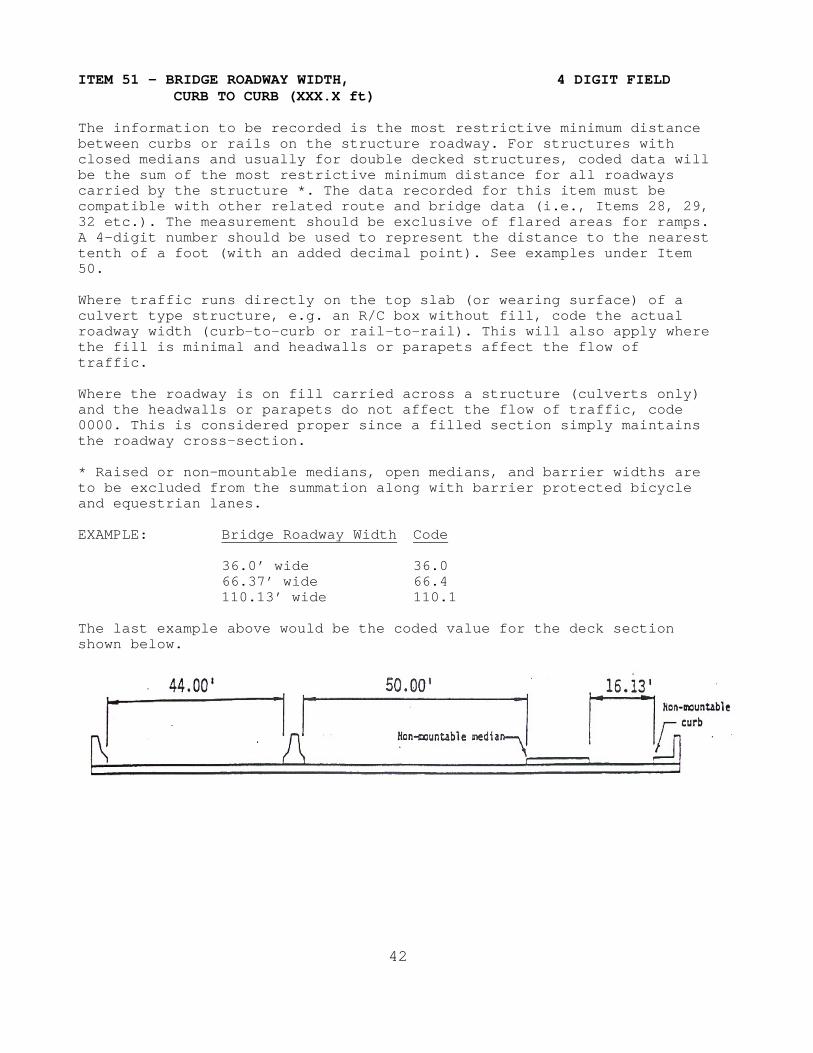
The information to be recorded is the most restrictive minimum distance between curbs or rails on the structure roadway. For structures with closed medians and usually for double decked structures, coded data will be the sum of the most restrictive minimum distance for all roadways carried by the structure *. The data recorded for this item must be compatible with other related route and bridge data (i.e., Items 28, 29, 32 etc.). The measurement should be exclusive of flared areas for ramps. A 4-digit number should be used to represent the distance to the nearest tenth of a foot (with an added decimal point). See examples under Item 50. Where traffic runs directly on the top slab (or wearing surface) of a culvert type structure, e.g. an R/C box without fill, code the actual roadway width (curb-to-curb or rail-to-rail). This will also apply where the fill is minimal and headwalls or parapets affect the flow of traffic. Where the roadway is on fill carried across a structure (culverts only) and the headwalls or parapets do not affect the flow of traffic, code 0000. This is considered proper since a filled section simply maintains the roadway cross-section. * Raised or non-mountable medians, open medians, and barrier widths are to be excluded from the summation along with barrier protected bicycle and equestrian lanes. EXAMPLE: Bridge Roadway Width Code
36.0’ wide 36.0 66.37’ wide 66.4 110.13’ wide 110.1
The last example above would be the coded value for the deck section shown below.
42

ITEM 52 - DECK WIDTH, OUT TO OUT 4 DIGIT FIELD (XXX.X ft)
Record and code a 4-digit number to show the out-to-out width of the deck to the nearest tenth of a foot (with an added decimal point) measured normal to roadway centerline. If the structure is a through structure, the number to be coded will represent the lateral clearance between superstructure members. The measurement should be exclusive of flared areas for ramps. See examples under Item 50. Where traffic runs directly on the top slab (or wearing surface) of the culvert (e.g., and R/C box without fill) code the actual width (out-to-out). This will also apply where the fill is minimal and the culvert headwalls affect the flow of traffic. However, for side-hill viaduct structures code the actual out-to-out structure width. Where the roadway is on a fill carried across a pipe or box culvert and the culvert headwalls or guard rails do not affect the flow of traffic, code 0000. This is considered proper inasmuch as a filled section over a culvert simply maintains the roadway cross-section. ITEM 53 - MINIMUM VERTICAL CLEARANCE 4 DIGIT FIELD
OVER BRIDGE ROADWAY (XX.XX ft) The information to be recorded for this item is the actual minimum vertical clearance over the bridge roadway, including shoulders, to any superstructure restriction, rounded down to the nearest inch. When no superstructure restriction exists above the bridge roadway, the clearance is therefore unlimited and should be coded 99.99. When a restriction is 100 feet or greater, code 99.99. A four-digit number should be coded to represent feet and hundredths of feet. EXAMPLES: Min. Vertical Clearance Code
16' – 1 1/2" 16.08 75' - 11" 75.92 115' - 6" 99.99 Unlimited 99.99
ITEM 54 - MINIMUM VERTICAL UNDERCLEARANCE 5 DIGIT FIELD
(X Code, XX.XX ft) Using a 1-digit code and a 4-digit number, record and code the minimum vertical clearance from the roadway or railroad track beneath the structure to the underside of the superstructure. (When both a railroad and highway are under the structure, code the most critical dimension.)
Segment Description Length 54A Reference feature 1 digit 54B Minimum Vertical Underclearance 4 digits
(continued)
43
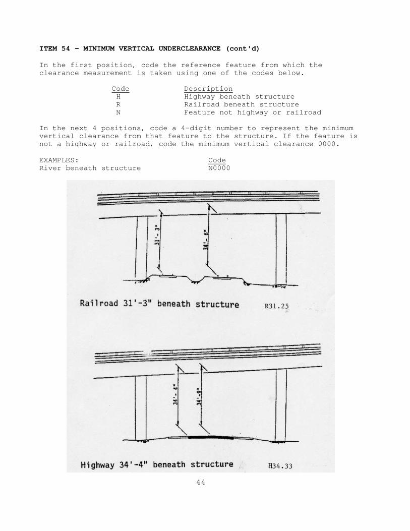
ITEM 54 - MINIMUM VERTICAL UNDERCLEARANCE (cont'd) In the first position, code the reference feature from which the clearance measurement is taken using one of the codes below.
Code Description H Highway beneath structure R Railroad beneath structure N Feature not highway or railroad
In the next 4 positions, code a 4-digit number to represent the minimum vertical clearance from that feature to the structure. If the feature is not a highway or railroad, code the minimum vertical clearance 0000. EXAMPLES: Code River beneath structure N0000
44

ITEM 55 - MINIMUM LATERAL UNDERCLEARANCE 4 DIGIT FIELD
ON RIGHT (X Code, XX.X ft)
Using a 1-digit code and a 3-digit number, record and code the minimum lateral underclearance on the right to the nearest tenth of a foot (with an added decimal point). When both a railroad and highway are under the structure, code the most critical dimension.
Segment Description Length
55A Reference feature 1 digit 55B Minimum Lateral Underclearance 3 digits
In the first position, code the reference feature from which the clearance measurement is taken using one of the codes below.
Code Description H Highway beneath structure R Railroad beneath structure N Feature not a highway or railroad
In the next 3 positions, code a 3-digit number to represent the minimum lateral underclearance on the right. The lateral clearance should be measured from the right edge of the roadway, excluding shoulders, (or from a point centered between rails of the right-hand track in the case of a railroad) to the nearest, substructure unit, rigid barrier, or toe of a slope steeper than 3 to 1. The clearance measurements to be recorded will be the minimum after measuring the clearance in both directions of travel. In the case of a dual highway this would mean the outside clearances of both roadways should be measured and the smaller distance recorded and coded. If two related features are below the bridge, measure both and record the lesser of the two. An explanation should be written as to what was recorded. If the feature beneath the structure is not a railroad or highway, code N and 000 to indicate not applicable. The presence of ramps is not considered in this item; therefore, the minimum lateral clearance on the right should be measured from the right edge of the through roadway. EXAMPLES: Code 55A Code55B Railroad 20.4’ centerline to pier R 20.4 Highway 20.2’ edge of travel way to pier H 20.2 Creek beneath structure N 000
(continued)
45

ITEM 55 - MINIMUM LATERAL UNDERCLEARANCE ON RIGHT (cont'd)
ITEM 56 - MINIMUM LATERAL UNDERCLEARANCE 3 DIGIT FIELD
ON LEFT (XX.X ft) (for divided highways, 1 way streets & ramps; not applicable to railroads)
The minimum clearance on the left (median side) of the roadway beneath the structure regardless of the direction of travel is to be recorded. As was explained in Item 55, the clearance on the left in both directions of travel should be measured and the smaller distance recorded. The clearance is to be measured from left edge of roadway (excluding shoulders) to the nearest substructure unit, rigid barrier, or toe of slope steeper than 3 to 1. In the case of a dual highway where there is no obstruction in the median area, a notation of "open" should be recorded and 99.9 should be coded. A 3-digit code to represent the distance to the nearest tenth of a foot should be used. Code 0 to indicate not applicable. ITEM 57 – NOT USED
46
CONDITION RATINGS Items 58 through 62 indicate the condition ratings. In order to promote uniformity between bridge inspectors, these guidelines will be used to rate and code Items 58, 59, 60, 61 and 62. The descriptive codes below are general. More specific guidelines are provided for each condition item to be rated. These ratings will be based on the existing in-place condition of the bridge as compared to its as-built condition. Evaluation is for the materials related, physical condition of the deck, superstructure, and substructure components of a bridge. The condition evaluations of channels, channel protection and culverts are also included. Condition codes are properly used when they provide an over all characterization of the general condition of the entire component being rated. Conversely, they are improperly used if they attempt to describe localized or nominally occurring instances of deterioration or disrepair. Correct assignment of a condition code must, therefore, consider both the severity of the deterioration or disrepair and the extent to which it is widespread throughout the component being rated. The load carrying capacity will not be used in evaluating condition items. The fact that a bridge was designed for less than current legal loads and may be posted shall have no influence upon condition ratings. The determination of which code applies to each of the items will be based on evaluation of all relevant factors and information. It is not necessary that all listed conditions under a numerical rating be observed in order for that code to be used. It is recognized that there are unique situations where judgment will be required. Portions of bridges that are being supported or strengthened by temporary members will be rated based on their actual condition; that is, the temporary members are not considered in the rating of the item. (See Item 103 - Temporary Structure Designation for the definition of a temporary bridge). Completed bridges not yet opened to traffic, if rated, shall be coded as new bridges open to traffic.
(continued)
47

CONDITION RATINGS (cont'd) The following general condition ratings shall be used as a guide in evaluating Item 58, 59, 60, and 62: Code Description N NOT APPLICABLE 9 EXCELLENT CONDITION 8 VERY GOOD CONDITION - no problems noted. 7 GOOD CONDITION - Minor problems. 6 SATISFACTORY CONDITION - structural elements show minor
deterioration. 5 FAIR CONDITION - all primary structural elements are sound but may
have minor section loss, cracking, spalling or scour. 4 POOR CONDITION - advanced section loss, deterioration, spalling or
scour. 3 SERIOUS CONDITION - loss of section, deterioration, spalling or
scour have seriously affected primary structural components. Local failures are possible. Fatigue cracks in steel or shear cracks in concrete may be present.
2 CRITICAL CONDITION - advanced deterioration of primary structural
elements. Fatigue cracks in steel or shear cracks in concrete may be present or scour may have removed substructure support. Unless closely monitored it may be necessary to close the bridge until corrective action is taken.
1 "IMMINENT" FAILURE CONDITION - major deterioration or section loss present in critical structural components or obvious vertical or horizontal movement affecting structure stability. Bridge is closed to traffic but corrective action may put back in light service.
0 FAILED CONDITION - out of service - beyond corrective action.
48

ITEM 58 - DECK 1 DIGIT FIELD This item describes the overall condition rating of the deck. Rate and code the condition of the deck in accordance with the above general condition ratings along with the guides provided under this item. Code N for all culverts. Concrete decks should be inspected for cracking, scaling, spalling, leaching, chloride contamination, pot-holing, delamination, and full or partial depth failures. Steel grid decks should be inspected for broken welds, broken grids, section loss, and growth of filled grids from corrosion. Timber decks should be inspected for splitting, crushing, fastener failure, and deterioration from rot. When determining the code for Item 58, the condition of the deck on the worst span of the bridge shall be indicated. The condition of the wearing surface/protective system, joints, expansion devices, curbs sidewalks, parapets, fascias, bridge rail, and scuppers shall not be considered in the overall deck evaluation. However their condition should be noted in the commentary portion of the inspection form. The following descriptive codes should be used as a guide in evaluating the deck condition for specific deck types.
CONCRETE BRIDGE DECKS - - - - - - - - - - - - -
Code Description N Use for all culverts. 9 New structure, two years or less in age, with no noticeable
deficiencies. 8 Structure older than two years of age with no noticeable
deficiencies. 7 Minor transverse or random cracks with light scaling (less than
1/4" depth with exposed aggregate). No spalling but has visible tire wear in the wheel lines. Electrical potential less than 0.20 or chloride content less than 1.0 pounds per cubic yard.
6 Sealable deck cracks. Medium scaling (1/4" to 1/2" in depth), 2%
or less of the deck spalled. Minor deterioration of deck edges or around scuppers. Minor leaching and/or staining present. Electrical potential between 0.21 and 0.25 or chloride content between 1.1 and 1.5 pounds per cubic yard.
(continued)
49

ITEM 58 - DECK (cont'd) Code Description 5 Excessive cracking (excessive being at 5-foot intervals or less
over the entire deck). 2% to 5% of the deck spalled. Heavy scaling (1/2" to 1" in depth). Heavy deterioration of deck edges or around scuppers. Considerable leaching and/or staining through deck. Partial but no full depth failures. Electrical potential between 0.26 and 0.30 or chloride content between 1.6 and 2.0 pounds per cubic yard.
4 5% to 50% of the deck spalled. Heavy leaching throughout the deck.
Full depth failures are imminent. Electrical potential over 0.30 or chloride content over 2.0 pounds per cubic yard.
3 Greater than 50% of deck spalled. Small full depth failures. This
rating will apply if severe or critical signs of structural distress are visible.
2 Full depth failures in deck. Closure of the bridge may be
necessary. 1 Bridge closed. Corrective action may put bridge back into light
service. 0 Bridge closed. Replacement necessary.
TIMBER BRIDGE DECKS - - - - - - - - - - - -
Code Description N Use for all culverts 9 New structure, two years or less in age with no noticeable
deficiencies. 8 Structure older than two years of age with no noticeable
deficiencies. Tightly secured to floor system. 7 Minor cracking or splitting. No loose planks or laminations. 6 Planking or laminated decking has light rot or crushing. A few
loose planks. Planks or laminated decking in need of replacement. 5 A number of planks or laminated decking cracked, split, rotted, or
crushed and in need of replacement. Many loose planks or laminations.
4 Numerous planks or laminated decking rotted, split, cracked, or
crushed. Majority of planks or laminations are loose. 3 Majority of planking or laminated deck is rotted, crushed and/or
split. The entire deck needs replaced.
(continued)
50

ITEM 58 - DECK (cont'd) Code Description 2 Extreme deterioration with partial deck failure. Closure of bridge may
be necessary. 1 Bridge closed. Corrective action may put bridge back into light
service. 0 Bridge closed. Replacement necessary.
STEEL BRIDGE DECKS - - - - - - - - - - - -
Code Description N Use for all culverts. 9 New structure, two years or less in age with no noticeable
deficiencies. 8 Structure older than two years of age with no noticeable
deficiencies. Tightly secured to floor system with no rust or cracking.
7 Loose at a few connections with minor rusting. 6 Considerable rusting. A few cracked welds and/or broken grids.
5 Heavy rusting with indications of initial section loss. A few
cracked welds and/or broken grids. 4 Heavy rusting with areas of moderate section loss. Numerous cracked
welds and/or broken grids. 3 Heavy rusting resulting in considerable section loss with a few
small holes through the deck. 2 Numerous small holes through the deck. Extreme section loss.
Closure of the bridge may be necessary. 1 Bridge closed. Corrective action may put bridge back into light
service. 0 Bridge closed. Replacement necessary.
51

ITEM 59 - SUPERSTRUCTURE 1 DIGIT FIELD This item describes the physical condition of all structural members. Rate and code the condition in accordance with the previously described general condition ratings along with the guide provided under this item. Code N for all culverts. The structural members should be inspected for signs of distress which may include cracking, deterioration, section loss, and malfunction or misalignment of bearings. Descriptions of superstructure member conditions shall be provided in the commentary portion of the inspection report. The inspector should determine if the bridge is fracture critical or has fracture critical components. Fracture critical components should receive careful attention because failure could lead to collapse of a span or the entire bridge. In-depth inspections should be scheduled when signs of distress are noted and in some cases partial disassembly may be required to ascertain the condition.
CONCRETE SUPERSTRUCTURES - - - - - - - - - - - - - - -
Code Description N Use for all culverts. 9 New structure, two years or less in age with no noticeable
deficiencies. 8 Structure older than two years of age with no noticeable
deficiencies. No visible cracking. 7 Minimal hairline cracks with no disintegration of concrete. No
staining present. 6 Minor hairline to 1/16" cracks with no disintegration of concrete.
Minor staining around the cracks. No spalling. 5 Moderate 1/16" to 1/8" cracks in concrete. Surface spalling up to
1/8". Heavy staining present. 4 Larger than 1/8" cracks in concrete. Spalling is beginning to
expose reinforcing steel.
(continued)
52

ITEM 59 - SUPERSTRUCTURE (cont'd) 3 Serious disintegration of concrete. Many open cracks may be
present. Reinforcing steel is exposed and rusting. 2 Concrete disintegrated on critical members. Reinforcing steel
severely corroded. Bridge closure may be necessary. 1 Bridge closed. Corrective action may put bridge back into light service. 0 Bridge closed. Replacement necessary.
STEEL SUPERSTRUCTURES - - - - - - - - - - - - -
Code Description N Use for all culverts. 9 New structure, two years or less in age with no noticeable
deficiencies. 8 Structure older than two years of age with no noticeable
deficiencies. No visible rust. 7 Minor surface rust. No cracks or section loss. 6 Heavy surface rust. Hinges may be showing signs of corrosion
problems. Random loose or missing bolts and/or rivets. 5 Initial section loss in critical stress areas. Fatigue or out-of-
plane-bending cracks may be present in non-critical areas. Minor misalignment of members. Hinges may be showing significant corrosion problems.
4 Significant section loss in critical stress areas. Minor fatigue or
out-of-plane-bending cracks may be present in major structural elements.
3 Serious section loss or major cracks in critical stress areas.
Numerous lose or missing bolts and/or rivets. Excessive misalignment of members. Hinges may be frozen from corrosion.
2 Severe section loss in many areas with holes rusted through major
structural members. Critical cracks in major structural elements. Bridge closure may be necessary.
1 Bridge closed. Corrective action may put bridge back into light
service. 0 Bridge closed. Replacement necessary.
53
TIMBER SUPERSTRUCTURES - - - - - - - - - - - - -
Code Description N Use for all culverts. 9 New structure, two years or less in age with no noticeable
deficiencies. 8 Structure older than two years of age with no noticeable
deficiencies. 7 Minor cracking or splitting of beams and/or stringers at
insignificant locations. 6 Minor decay, cracking, splitting, or crushing of beams and/or
stringers. 5 Moderate decay, cracking, splitting, or crushing of beams and/or
stringers. 4 Substantial decay, cracking, splitting, or crushing of beams and/or
stringers. 3 Extensive decay, cracking, splitting, or crushing of beams and/or
stringers. 2 Imminent failure of beams and/or stringers. Serious cracking,
crushing, splitting or decay of beams or stringers may have caused settlement of deck. Bridge closure may be necessary.
1 Bridge closed. Corrective action may put bridge back into light
service. 0 Bridge closed. Replacement necessary. ITEM 60 - SUBSTRUCTURE 1 DIGIT FIELD This item describes the physical condition of piers, abutments, piles, fenders, footings, and other substructure components. All substructure elements should be inspected for visible signs of distress including evidence of cracking, section loss, settlement, misalignment, scour, collision damage, and corrosion. The rating factor given to Item 60 should be consistent with the one given to Item 113 whenever a rating factor of 2 or below is determined for Item 113 – Scour Critical Bridges. The substructure condition rating shall be made independent of the deck and superstructure. When determining the condition rating for the substructure, the condition of the worst substructure unit shall be indicated in Item 60. Code N for all culverts.
(continued)
54

Item 60 – SUBSTRUCTURE (cont'd) Integral-abutment wingwalls to the first construction or expansion joint shall be included in the evaluation. For non-integral superstructure and substructure units, the substructure shall be considered as the portion below the bearings. For structures where the superstructure and substructure are integral, the substructure shall be considered as the portion below the superstructure. Comprehensive rehabilitation of the substructure units will normally restore the substructure condition to a least a rating of 7. Rate and code the substructure condition in accordance with the previously described general condition rating along with the following additional descriptive codes (which shall be used as guide in evaluating the substructure condition). Code Description N Use for all culverts. 9 New structure, two years or less in age with no noticeable
deficiencies. 8 Structure older than two years with no noticeable deficiencies.
Insignificant scrape marks caused by drift of collision. 7 Minor shrinkage cracks, H/L to 1/32" light scaling, or
insignificant spalling which does not expose reinforcing steel. Insignificant damage caused by drift or collision. No misalignment. No corrective action required.
6 Deterioration or initial disintegration, minor to moderate cracking
(1/32" to 1/16") with leaching, or spalls on concrete or masonry unit with no effect on bearing area. Rusting of steel without section loss. Insignificant decay, cracking, splitting, or crushing of timber. Local scouring has occurred near substructure footing without misalignment.
5 Moderate deterioration, spalling, cracking (1/16" +), and/or
leaching on concrete or masonry units with little or no loss of bearing area. Initial loss of steel section. Significant decay, cracking, splitting, or crushing of timber. A few timber members may need replacement. Moderate exposure of pile as a result of erosion, reducing the penetration and affecting the unit stability. May require additional cross-bracing. Scour is becoming more prominent with a possibility of exposing top of footing, but no misalignment of settlement noted.
4 Many concrete or masonry units show substantial loss with exposed
reinforcing steel. Measurable section loss in steel members. A substantial number of timber piles require replacement (up to 25% of piles need replaced in any one bent or abutment). Extensive exposure of pile as a result of erosion, reducing the penetration and affecting the stability of the unit. Minor scouring or undermining of footing evident. Additional cross-bracing or back-filling is required. (continued)
55
ITEM 60 - SUBSTRUCTURE (cont’d) Code Description 3 Structural cracks in concrete and masonry units. Extensive section
loss in steel members. Piling and caps in a substantial number of timber bents require replacement due to decay, cracking, splitting, or crushing. Between 26% and 50% of the piles need replaced in any one bent or abutment. Severe scouring or undermining of footings affecting the stability of the units, requiring corrective action. Minor settlement of the substructure may have occurred.
2 Bearing areas seriously deteriorated with considerable loss of
bearing area. More than 50% of piles need replaced in any one bent or abutment. Blocking and shoring considered necessary to maintain the safety and alignment of the structure. Substructure is near state of collapse due to scour. Unless closely monitored it may be necessary to close the bridge until corrective action is taken. If Scour Item 113 = 2, substructure cannot be coded higher than a 2.
1 Bridge closed. Corrective action may put bridge back into light
service. 0 Bridge closed. Replacement necessary. ITEM 61 - CHANNEL AND CHANNEL PROTECTION 1 DIGIT FIELD This item deals with the physical conditions associated with the flow of water through the bridge. Stream stability, condition of the channel, rip-rap, slope protection and stream control devices (such as spur dikes) are included in the evaluation. The inspector should be particularly concerned with visible signs of excessive water velocity, which may affect undermining of slope protection or footings, erosion of banks, and realignment of the stream which may result in immediate or potential problems. Accumulation of drift and debris on the superstructure and substructure should be noted. Rate and code the condition of the channel in accordance with the previously described general condition ratings and the following descriptive codes: Code Description N Not applicable. Use when bridge is not over a waterway. 9 No noticeable or noteworthy deficiencies which affect the condition
of the channel. 8 Banks are protected or well vegetated. River control devices such
as spur dikes and embankment protection are not required or are in stable condition.
7 Bank protection is in need of minor repairs. River control devices
and embankment protection have minor damage. Banks and/or channel have minor amounts of drift. Minor local scour developing near substructure. (continued)
56

ITEM 61 - CHANNEL AND CHANNEL PROTECTION (cont'd) Code Description 6 Bank is beginning to slump. River control devices and embankment
protection have widespread minor damage. There is minor stream bed movement evident. Debris is restricting the waterway slightly. Scour holes deepening.
5 Bank protection is being eroded. River control devices and/or
embankment have major damage. Trees and brush restrict the channel. Scour holes are becoming more prominent, affecting the stability of the substructure.
4 Bank and embankment protection undermined with corrective action
required. River control devices have severe damage. Large deposits of debris in the waterway.
3 Bank protection has failed completely. River control devices have
been destroyed. Stream bed aggradation, degradation or lateral movement has changed the waterway to now threaten the bridge and/or approach roadway.
2 The waterway has changed and now threatens the bridge and/or
embankment. Scour is of sufficient depth beneath footing that substructure is near state of collapse. Settlement of abutment is occurring. Closure of bridge may be necessary because of channel failure.
1 Bridge closed because of channel failure. Corrective action may put
bridge back into light service. 0 Bridge closed because of channel failure. Total replacement
necessary. ITEM 62 - CULVERTS 1 DIGIT FIELD This item evaluates the alignment, settlement, joints, structural condition, scour, and other items associated with culverts. The rating code is intended to be an overall condition evaluation of the culvert. Integral wingwalls will be included to the first construction or expansion joint. Comprehensive rehabilitation of culverts will normally restore the unit to minimum rating of 7. For a detailed discussion regarding the inspection and rating of culverts, consult Report No. FHWA-IP-86--2, Culvert Inspection Manual, July 1986. Item 58 - Deck, Item 59 - Superstructure, and Item 60 - Substructure shall be coded N for all culverts. Rate and code the condition in accordance with the previously described general condition ratings and the following descriptive codes: (continued)
57

ITEM 62 - CULVERTS (cont’d) Code Description N Not applicable. Use when structure is not a culvert. 9 New condition. 8 No noticeable or noteworthy deficiencies which affect the condition
of the culvert. Insignificant scrape marks caused by drift. 7 Shrinkage cracks, light scaling, and insignificant spalling which
does not expose reinforcing steel. Insignificant damage caused by drift with no misalignment and not requiring corrective action. Minor scouring has occurred near curtain walls, wingwalls, or pipes. Metal culverts have a smooth symmetrical curvature with superficial corrosion and no pitting.
6 Deterioration or initial disintegration minor chloride
contamination, cracking with leaching, or spalls on concrete or masonry walls and slabs. Local minor scouring at curtain walls, wingwalls, or pipes. Metal culverts have a smooth curvature, non-symmetrical shape, significant corrosion or moderate pitting.
5 Moderate to major deterioration or disintegration, extensive
cracking and leaching, or spalls on concrete or masonry walls and slabs. Minor settlement or misalignment. Noticeable scouring or erosion at curtain walls, wingwalls, or pipes. Metal culverts have significant distortion and deflection in one section, significant corrosion or deep pitting.
4 Large spalls, heavy scaling, wide cracks, considerable
efflorescence or opened construction joint permitting loss of backfill. Considerable settlement or misalignment. Considerable scouring or erosion at curtain walls, wingwalls or pipes. Metal culverts have significant distortion and deflection throughout, extensive corrosion and deep pitting.
3 Any condition described in Code 4 but which is excessive in scope.
Severe movement or differential settlement of the segments, or loss of fill. Holes may exist in walls or slabs. Integral wingwalls nearly severed from culvert. Severe scour or erosion at curtain walls, wingwalls and pipes. Metal culverts have extreme distortion and deflection in one section, extensive corrosion or deep pitting with scattered perforations.
2 Integral wingwalls collapsed, severe settlement of roadway due to
loss of fill. Section of culvert may have failed and can no longer support embankment. Complete undermining at curtain walls and pipes. Corrective action required to maintain traffic. Metal culverts have extreme distortion and deflection throughout with extensive perforations due to corrosion.
1 Bridge closed. Corrective action may put back in light service. 0 Bridge closed. Total replacement necessary.
58

ITEM 63 - METHOD USED TO DETERMINE OPERATING RATING 1 DIGIT FIELD Use one of the codes below to indicate which load rating method was used to determine the operating rating coded in Item 64 for this structure. For inventory/initial inspections, where the operating rating is assigned by the inspector, a code of 5 will be assigned. This item should only be changed by the ITD Load Rating Engineer. Code Description
0 Field Evaluation and Documented Engineering Judgment 1 Load Factor (LFR) 2 Allowable Stress (ASR) 3 Load and Resistance Factor (LRFR) 4 Load Testing 5 No rating analysis or evaluation performed 6 LFR reported by RF method using HS20 Load 7 ASR reported by RF method using HS20 Load 8 LRFR reported by RF method using HL93 A Assigned rating based on Load Factor Design(LFD)reported in tons B Assigned ratings based on Allowable Stress Design(ASD) reported in tons C Assigned ratings based on Load and Resistance Factor Design(LRRD) reported in tons D Assigned rating based on LFD reported by RF using HS20 loading E Assigned rating based on ASD reported by RF using HS20 loadings F Assigned rating based on LRFD reported by RF using HS20 loadings
ITEM 64 - OPERATING RATING (TONS) 2 DIGIT FIELD This capacity rating, referred to as the operating rating, will result in the absolute maximum permissible load level to which the structure may be subjected for the vehicle type used in the rating. At this time only the HS loading will be used to determine the operating rating. The initial operating rating will likely be assigned by the inspector and all subsequent operating ratings will be determined by the ITD Load Rating Engineer. For initial operating ratings, use the following table: Design Load Operating Rating H10 22* H15 32* HS15 43 H20 45 HS20 60 HS25 75 HL93 46 Railroad 00 Pedestrian 00 Temporary bridge 00 (continued)
59

Shored-up bridge 03** Structure under sufficient fill that live load is negligible 99*** * Equivalent HS tonnage ** Load capacity without shoring *** For single spans, the effect of live load may be neglected when the depth of fill is more than 8 feet and exceeds the span length; for multiple spans it may be neglected when the depth of fill exceeds the distance between faces of end supports or abutments. AASHTO Standard Specifications for Highway Bridges, 17th Edition, Section 6.4.2 When inspectors code the initial inventory and operating ratings, a “(B)Initial Analysis Required” will be coded for Load Rating Status. If inventory and operating ratings need to be recalculated, under the Agency tab, check “Needs Re-Analysis”. The bridge should be considered for reanalysis if any of the following conditions are present:
• The condition code of the deck (Item 58), superstructure (Item 59) or substructure (Item 60) is 4 or less.
• The condition code of the culvert (Item 62) is 5 or less.
• An additional wearing surface of 1 inch or more had been added to the deck.
• The bridge cannot carry a minimum of 3.0 tons of live load.
• A temporary bridge is present.
• The bridge is shored up.
If the inspector questions that the inventory and operating ratings adequately reflect the current status of the bridge for reasons other than itemized above, make note of it in the “BIE” section of the Notes tab. An example of this situation would be the deck has a long-existing five inch overlay for which the bridge may have not been designed. In these cases do not check “Needs Re-Analysis”. ITEM 65 - METHOD USED TO DETERMINE INVENTORY RATING 1 DIGIT FIELD Use one of the codes below to indicate which load rating method was used to determine the inventory rating coded in Item 66 for this structure. For inventory/initial inspections, where the inventory rating is assigned by the inspector, a code of 5 will be assigned. This item should only be changed by the ITD Load Rating Engineer. Code Description
0 Field Evaluation and Documented Engineering Judgment 1 Load Factor (LFR) 2 Allowable Stress (ASR) 3 Load and Resistance Factor (LRFR)
(continued)
60

4 Load Testing 5 No rating analysis or evaluation performed 6 LFR reported by RF method using HS20 Load 7 ASR reported by RF method using HS20 Load 8 LRFR reported by RF method using HL93 A Assigned rating based on Load Factor Design(LFD)reported in tons B Assigned ratings based on Allowable Stress Design(ASD) reported in tons C Assigned ratings based on Load and Resistance Factor Design(LRRD) reported in tons D Assigned rating based on LFD reported by RF using HS20 loading E Assigned rating based on ASD reported by RF using HS20 loadings F Assigned rating based on LRFD reported by RF using HS20 loadings
ITEM 66 - INVENTORY RATING (TONS) 2 DIGIT FIELD This capacity rating, referred to as the inventory rating, is the safe load level to which the structure can be subjected for an indefinite period of time. At this time only the HS loading will be used to determine the inventory rating. The initial inventory rating will likely be assigned by the inspector and all subsequent inventory ratings will be determined by the ITD Load Rating Engineer. For initial inventory ratings, use the following table: Design Load Inventory Rating H10 13* H15 19* HS15 27 H20 26 HS20 36 HS25 45 HL93 36 Railroad 00 Pedestrian 00 Temporary bridge 00 Shored-up bridge 03** Structure under sufficient fill that live load may be neglected 99*** * Equivalent HS tonnage ** Load capacity without shoring *** For single spans, the effect of live load may be neglected when the depth of fill is more than 8 feet and exceeds the span length; for multiple spans it may be neglected when the depth of fill exceeds the distance between faces of end supports or abutments. AASHTO Standard Specifications for Highway Bridges, 17th Edition, Section 6.4.2 When inspectors code the initial inventory and operating ratings, a “(B)Initial Analysis Required” will be coded for Load Rating Status.
61

If inventory and operating ratings need to be recalculated, under the Agency tab, check “Needs Re-Analysis”. The bridge should be considered for reanalysis if any of the following conditions are present:
• The condition code of the deck (Item 58), superstructure (Item 59) or substructure (Item 60) is 4 or less.
• The condition code of the culvert (Item 62) is 5 or less.
• An additional wearing surface of 1 inch or more had been added to the deck.
• The bridge cannot carry a minimum of 3.0 tons of live load.
• A temporary bridge is present.
• The bridge is shored up.
If the inspector questions the inventory and operating ratings adequately reflect the current status of the bridge for reasons other than itemized above, make note of it in the “BIE” section of the Notes tab. An example of this situation would be the deck has a long-existing five inch overlay for which the bridge may have not been designed. In these cases do not check “Needs Re-Analysis”.
62
APPRAISAL
The items in the Appraisal section are used to evaluate a bridge in relation to the level of service that it provides on the highway system of which it is a part. The structure will be compared to a new one (built to current standards for that particular type of road) as further defined below. Special criteria for rating Item 72 - Approach Roadway Alignment is given under that item description. Item 67, 68, 69, 71 and 72 will be coded with one-digit code that indicates the appraisal rating for the item. The ratings and codes are as follows: Code Description N Not Applicable 9 Superior to present desirable criteria 8 Equal to present desirable criteria 7 Better than present minimum criteria 6 Equal to present minimum criteria 5 Somewhat better than minimum adequacy to tolerate being left in
place as is. 4 Meets minimum tolerable limits to be left in place as is 3 Basically intolerable requiring high priority of corrective action. 2 Basically intolerable requiring high priority of replacement. 1 This value of rating code not used 0 Bridge Closed Tables are provided to evaluate items 67, 68, 69, and 71, and shall be used to determine the appropriate code for these items. They have been developed to closely match the descriptions for the appraisal evaluation codes of 0 to 9. The tables shall be used in all instances to evaluate the item based on the designated data in the inventory, even if a table does not appear to match the descriptive codes. For unusual cases where the site data does not exactly agree with the table criteria, use the most appropriate table to evaluate the item. Level of service goals is a concept that several States have introduced into their bridge management to determine the need for bridge improvements. Level of service goals are target values for selected bridge characteristics that are used to assess bridge adequacy. The goals may vary depending on the highway functional classification, traffic volume, and other factors. The goals are set with the recognition that widely varying traffic needs exist throughout highway systems and that many bridges on local roads can adequately serve traffic needs with lower load and capacity geometric standards than would be necessary for bridges on heavily traveled main highways.
63

The degree to which a bridge is deficient can be measured by comparing bridge characteristics with level of service goals. Shortfalls from the goals determine the type and extent of improvement needs. The shortfalls are useful for comparing bridge needs and setting improvement priorities. Needs determined by level of service goals which are graduated to traffic levels and the characteristics of vehicles served can differ greatly from those determined by a single standard that applies to all bridges, for example the AASHTO A Policy on Geometric Design of Highway and Streets 1984. However, the application of particular level of service concepts as developed by individual States do not result in the desired consistency when evaluating structures on a national basis. If uniformity and consistency are to be achieved, similar structures, roadway and vehicle characteristics must be evaluated using identical standards. Therefore, tables and charts have been developed which shall be used to evaluate and code appraisal items for all bridges submitted to the National Bridge Inventory regardless of individual State criteria used to evaluate bridges. Completed bridges not yet opened to traffic, if rated, shall be appraised as if open to traffic. Design values, for example ADT, shall be used for evaluation. The data provided will included a code of G for Item 41 - Structure Open, Posted, or Closed to Traffic.
64

ITEM 67 - STRUCTURAL EVALUATION 1 DIGIT FIELD Please note that BrM will automatically calculate this Item. The definition and coding below is just for your information. The following specifications are used by the Edit/Update Program: For structures other than culverts, the lowest of the codes obtained from Item 59 - Superstructure, Item 60 - Substructure, or Table 1 is used. For culverts, the lowest of the codes obtained from Item 62 - Culverts, or Table 1 is used. If Item 59, Item 60 or Item 62 is coded 1, then Item 67 is equal to zero (0), regardless of whether the structure is actually closed. However, if the structure is closed, it does not mean that this value is zero (0) unless the overall condition and appraisal ratings indicate that a code of 0 is appropriate. TABLE 1 NOTES: 1. Use the lower rating code for values between those lines listed in
the table. 2. Inventory Ratings are shown in tons with decimal point. 3. To use Table 1, the Inventory Rating must be the coded HS rating or
its equivalent. If the comparable HS equivalent is not calculated for the controlling rating, using a factor to determine the HS equivalent is acceptable even though converting other rating loads to an HS equivalent is not a constant.
4. All bridges with Item 26 - Functional Class coded Interstate,
Freeway or Expressway shall be evaluated using the ADT column of >5000 regardless of the actual ADT on the bridge.
(continued)
65

ITEM 67 STRUCTURAL EVALUATION (cont'd) STRUCTURAL EVALUATION RATING - Item 67 by comparison of ADT - Item 29 and Inventory Rating - Item 66
TABLE 1
Structural evaluation rating code
INVENTORY RATING
AVERAGE DAILY TRAFFIC (ADT) 0-500 501-5000 >5000
9
>236*
(HS20)**
>236
(HS20)
>236
(HS20)
8
236
(HS20)
236
(HS20)
236
(HS20)
7
231
(HS17)
231
(HS17)
231
(HS17)
6
223
(HS13)
225
(HS14)
227
(HS15)
5
218
(HS10)
220
(HS11)
222
(HS12)
4
212
(HS7)
214
(HS8)
218
(HS10)
3
Inventory rating less than value in rating code
of 4 and requiring corrective action.
2
Inventory rating less than value in rating code
of 4 requiring replacement.
0
Bridge closed.
* Coded HS rating load (typical) ** HS designation (typical)
66

ITEM 68 - DECK GEOMETRY 1 DIGIT FIELD Please note that BrM will automatically calculate this Item. The definition and coding below is just for your information. The following specifications are used by the Edit/Update Program: The overall rating for deck geometry includes two evaluations: (a) the curb-to curb or face-to-face of rail bridge width using Table 2A, B, C or D and (b) the minimum vertical clearance over the bridge roadway using Table 2E. The lower of the codes obtained from these tables is used by the Edit/Update Program. When an individual table lists several deck geometry rating codes for the same roadway width under a specific ADT, the lower code is used. (For example, Table 2A lists deck geometry rating codes of 6, 7 and 8 for a 44 foot roadway width and an ADT of >5000. Use the code of 6.). For values between those listed in the tables, the lower code is used. The curb-to-curb or face-to-face of rail dimension shall be taken from Item 51 - Bridge Roadway Width, Curb-to-Curb. Item 53 - Minimum Vertical Clearance Over Bridge Roadway is used to evaluate the vertical clearance. For culverts which have Item 51 - Bridge Roadway Width coded 0000, the deck Geometry code will be equal to N. The values provided in the tables are for rating purposes only. Current design standards must be used for structure design or rehabilitation.
(continued)
67

ITEM 68 - DECK GEOMETRY (cont'd) DECK GEOMETRY RATING - Item 68 by comparison of ADT - Item 29 and bridge roadway width, Curb-to-curb - Item 51
TABLE 2A
TABLE 2B
Deck Geometry Rating Code
Bridge Roadway Width
2 lanes; 2 way traffic
Bridge Roadway
Width 1 lane; 2 way
traffic
ADT (both directions)
ADT (both directions)
0-100
101-400
401-1000
1001-2000
2001-5000
>5000
0-100
>100
9
>32
>36
>40
>44
>44
>44
-
-
8
32
36
40
44
44
44
15’-11"
-
7
28
32
36
40
44
44
15
-
6
24
28
30
34
40
44
14
-
5
20
24
26
28
34
38
13
-
4
18
20
22
24
28
32
(28*)
12
-
3
16
18
20
22
26
30
(26*)
11
15’-11"
2
Any width less than required for a rating code of 3 and structure is open.
0
Bridge closed.
*Use value in parenthesis for bridges longer than 200’. NOTES: 1. Use the lower rating code for values between those listed in the
table. 2. Dimensions are in feet. 3. For 3 or more undivided lanes of 2-way traffic, use Table 2C. Other
Multi-lane Divided Facilities. 4. Do not use Table 2B for code 9. Also do not us Table 2B for codes 8
through 4 inclusive when the ADT >100. Single lane bridges less than 16 feet wide carrying 2-way traffic are always appraised at 3 or below if they carry more than and ADT of 100.
5. One lane bridges 16’ or greater in roadway widths, which are not ramps, are, evaluated as 2-lane bridge using table 2A.
(continued)
68

ITEM 68 - DECK GEOMETRY (cont'd)
DECK GEOMETRY RATING - ITEM 68 by comparison of number of lanes - Item 28 and bridge roadway width, curb to curb - Item 51
TABLE 2C
TABLE 2D Deck Geometry Rating Code
Bridge Roadway Width
2 or more lanes
Bridge Roadway
Width One way Traffic
Interstate
Other Multi-lane
Divided Facilities
Ramps Only
2 lanes
3 or more
lanes
2 lanes
3 or more lanes
1 lane
2 or more
lanes
9
>42
>12N+24
>42
>12N+18
>26
>12N+12
8
42
12N+24
42
12N+18
26
12N+12
7
40
12N+20
38
12N+15
24
12N+10
6
38
12N+16
36
12N+12
22
12N+8
5
36
12N+14
33
11N+10
20
12N+6
4
34 (29)*
11N+12
(11N+7)*
30
11N+6
18
12N+4
3
33 (28)*
11N+11 (11N+6)
27
11N+5
16
12N+2
2
Any width less than required for a rating code of 3 and the structure is open.
1
Bridge closed.
*Use value in parentheses for bridges longer than 200’. N = number of lanes of traffic Notes: 1. Use the lower rating code for values between those listed in the
tables. 2. Dimensions are in feet. 3. Use Table 2C, Other Multilane Divided facilities, for 3 or more
undivided lanes of 2 way traffic.
(continued)
69

ITEM 68 - DECK GEOMETRY (cont'd) DECK GEOMETRY - ITEM 68 by comparison of Minimum Vertical Clearance over Bridge Roadway - Item 53 and Functional Classification - Item 26
TABLE 2E
Deck Geometry Rating Code
Minimum Vertical Clearance
Functional Class
Interstate
Other Principal and Minor Arterials
Major and Minor
Collectors and Locals
All routes (Except as
noted for urban areas)
Business Routes,
Urban Areas*
9
>17’ - 0"
>16’ - 6"
>16’ - 6"
>16’ - 6"
8
17’ - 0"
16’ - 6"
16’ - 6"
16’ - 6"
7
16’ - 9"
15’ - 6"
15’ - 6"
15’ - 6"
6
16’ - 6"
14’ - 6"
14’ - 6"
14’ - 6"
5
15’ - 9"
14’ - 3"
14’ - 3"
14’ - 3"
4
15’ - 0"
14’ - 0"
14’ - 0"
14’ - 0"
3
Vertical clearance less than value in rating code 4 and requiring corrective action.
2
Vertical clearance less than value in rating code 4 and requiring replacement.
0
Bridge closed.
* Use for routes in highly developed urban areas only when there is an alternative Interstate, freeway or expressway facility with a minimum of 16’ - 0" clearance. NOTES: 1. Use the lower rating code for values between those listed in the
table. 2. Dimensions are in feet.
70

ITEM 69 - UNDERCLEARANCES, VERTICAL 1 DIGIT FIELD AND HORIZONTAL
Please note that BrM will automatically calculate this Item. The definition and coding below is just for your information. This refers to vertical and horizontal underclearances from the through roadway to the superstructure or substructure units, respectively. Code "N" is used unless the bridge is over a highway or railroad. The vertical underclearance shall be evaluated using Table 3A. The horizontal underclearance shall be evaluated using Table 3B. The lower of the codes obtained from Table 3A and Table 3B shall be used. Bridges seldom are closed due to deficient underclearance. However, they may be good candidates for rehabilitation or replacement. Item 54 - Minimum Vertical Underclearance, Item 55 - Minimum Lateral Underclearance on Right and Item 56 - Minimum Lateral Underclearance on left shall be used to evaluate this item. The functional classification to be used in the table is for the underpassing route. Therefore, the functional classification must be obtained from the record for the route "under" the bridge (see Item 5 - Inventory Route). If the underpassing route is not on a Federal-aid system, is not a defense route, or is not otherwise important, use the Major and Minor Collector and Locals column in Tables 3A and 3B. Tables 3A and 3B are on the following pages.
(continued)
71

ITEM 69 - UNDERCLEARANCES, VERTICAL AND HORIZONTAL (cont'd)
UNDERCLEARANCE, VERTICAL - ITEM 69 by Comparison of Minimum Vertical Underclearance - Item 54 and Functional Classification - Item 26
TABLE 3A
Under Clearance
Rating Code
Minimum Vertical Underclearance
Functional Class
Railroad
Interstate and other
Freeway
Other
Principal and Minor Arterials
Major and
Minor Collectors and Locals
All
Routes (except as noted for urban
area)
Undesignated
Routes, Urban Areas*
9
>17’ - 0"
>16’ - 6"
>16’ - 6"
>16’ - 6"
>23’ - 0"
8
17’ - 0"
16’ - 6"
16’ - 6"
16’ - 6"
23’ - 0"
7
16’ - 9"
15’ - 6"
15’ - 6"
15’ - 6"
22’ - 6"
6
16’ - 6"
14’ - 6"
14’ - 6"
14’ - 6"
22’ - 0"
5
15’ - 9"
14’ - 3"
14’ - 3"
14’ - 3"
21’ - 0"
4
15’ - 0"
14’ - 0"
14’ - 0"
14’ - 0"
20’ - 0"
3
Underclearance less than value in rating code of 4 and
requiring corrective action. 2
Underclearance less than value in rating code of 4 and
requiring replacement. 0
Bridge closed.
*Use for routes in highly developed urban areas only when there is and alternative Interstate, freeway or expressway facility with a minimum of 16’ - 0 clearance. NOTES: 1. Use the lower rating code for values between those listed in the
table. 2. Dimensions are in feet. 3. The functional classification of the under-passing route shall be
used in the evaluation. If an "under" record is not coded, the under-passing route shall be considered a major or minor collector or a local road.
(continued)
72

ITEM 69 - UNDERCLEARANCES, VERTICAL AND HORIZONTAL (cont'd)
UNDERCLEARANCE, HORIZONTAL - ITEM 69 by Comparison of Minimum Lateral Underclearances Right & Left - Items 55 & 56 and Functional Classification - Item 26
TABLE 3B Under-clear-ance Rating Code
Minimum Lateral Underclearance
Functional Class
One-way Traffic
Two-way Traffic
Railroad
Principal Arterials Interstate, Freeways or Expressways
Other
Principal and Minor Arterials
Major & Minor
Collectors and Locals
Main Line
Ramp left
right
left
right
9
>30
>30
>4
>10
>30
>12
>20
8
30
30
4
10
30
12
20
7
18
21
3
9
21
11
17
6
6
12
2
8
12
10
14
5
5
11
2
6
10
8
11
4
4
10
2
4
8
6
8
3
Underclearance less than value in rating code of 4 and requiring corrective action.
2
Underclearance less than value in rating code of 4 and requiring replacement.
0
Bridge closed.
NOTES: 1. Use the lower rating code for values between those listed in the
tables. 2. Dimensions are in feet. 3. When acceleration or deceleration lanes or ramps are provided under
2-way traffic, use the value from the right ramp column to determine code.
4. The functional classification of the under-passing route shall be used in the evaluation. If an "under" record is not coded, the under-passing route shall be considered a major or minor collector.
73

ITEM 70 - BRIDGE POSTING 1 DIGIT FIELD The National Bridge Inspection Standards require the posting of load limits only if the maximum legal load in the State produces stresses in excess of the operating stress level. If the load capacity at the operating level is such that posting is required, this item shall be coded 0 through 4. If no posting is required at the operating level, this item shall be coded 5. This item evaluates the load capacity of a bridge in comparison to the State legal load. It differs from Item 67 - Structural Evaluation in that Item 67 uses the inventory rating while the bridge posting requirement is based on the operating rating. Although posting a bridge for load-carrying capacity is required only when the maximum legal load exceeds the operating rating capacity, highway agencies may choose to post at lower rating capacities. This posting practice may appear to produce conflicting coding when Item 41 - Structure Open, Posted or Closed to Traffic is coded to show the bridge as actually posted at the site and Item 70 - Bridge Posting is coded as bridge posting is not required. Since different criteria are used for coding these 2 items, this coding is acceptable and correct when the highway agency elects to post at less than the operating rating stress level. Item 70 shall be coded 0 through 4 only if the legal load of the State exceeds that permitted under the operating rating. The use or presence of a temporary bridge affects the coding. The load capacity shall reflect the actual capacity of the temporary bridge at the operating rating. This also applies to bridges shored up or repaired on a temporary basis.
Code Description 0, 1, 2, 3 or 4 Posting required
5 No posting required The degree that the operating rating stress level is under the maximum legal load stress level may be used to differentiate between codes. As a guide and for coding purposes only, the following values may be used to code this item or use the table in Appendix H. Code Relationship of Operating Rating Description Stress to Legal Load Stress 5 Equal to or above legal loads No posting required 4 0.1 - 9.9% below Posting required
3 10.0 - 19.9% below Posting required 2 20.0 - 29.9% below Posting required.
1 30.0 - 39.9% below Posting required. 0 > 39.9% below Posting required.
74

ITEM 71 - WATERWAY ADEQUACY 1 DIGIT FIELD This item appraises the waterway opening with respect to passage of flow through the bridge. The following codes shall be used in evaluating waterway adequacy. Site conditions may warrant somewhat higher or lower ratings than indicated by the table (e.g., flooding of an urban area due to a restricted bridge opening). Where overtopping frequency information is available, the descriptions given in the table for chance of overtopping mean the following:
Remote greater than 100 years Slight 11 to 100 years Occasional 3 to 10 years Frequent less than 3 years
Adjectives describing traffic delays mean the following:
Insignificant Minor inconvenience. Highway passable in a matter of hours.
Significant Traffic delays of up to several days. Severe Long term delays to traffic with resulting
hardship.
FUNCTIONAL CLASSIFICATION
DESCRIPTION
Principal Arterials - Interstate Freeways or Expressway
Principal and Minor Arterials and Major Collectors
Minor Collectors Locals
N
N
N
Bridge not over waterway.
9
9
9
Bridge deck and roadway approached above floodwater elevations (high water). Chance of over-topping is remote.
8
8
8
Bridge deck above roadway approaches. Slight chance of overtopping roadway approaches.
6
6
7
Slight chance of over-topping bridge deck and roadway approaches.
(Table continued on next page)
75

ITEM 71 - WATERWAY ADEQUACY (cont'd) FUNCTIONAL CLASSIFICATION
DESCRIPTION
Principal
Arterials - Interstate Freeways or Expressway
Principal and Minor Arterials and Major Collectors
Minor
Collectors Locals
4
5
6
Bridge deck above roadway approaches. Occasional overtopping of roadway
approaches with insignificant traffic
delays. 3
4
5
Bridge deck above road approaches. Occasional overtopping of roadway
approaches with significant traffic delays.
2
3
4
Occasional overtopping of
bridge deck & roadway approaches w/significant
traffic delays. 2
2
3
Frequent overtopping of bridge deck & roadway
approaches w/significant traffic delays.
2
2
2
Occasional or frequent
overtopping of bridge deck & roadway approaches with severe traffic delays.
0
0
0
Bridge closed.
76

ITEM 72 - APPROACH ROADWAY ALIGNMENT 1 DIGIT FIELD Code the rating based on the adequacy of the approach roadway alignment. This item identifies those bridges which do not function properly or adequately due to the alignment of the approaches. It is not intended that the approach roadway alignment be compared to current standards but rather to the existing highway alignment. This concept differs from other appraisal evaluations. The establishment of set criteria to be used at all bridge sites is not appropriate for this item. The basic criteria are how the alignment of the roadway approaches to the bridge relates to the general highway alignment for the section of highway the bridge is on. The individual structure shall be rated in accordance with the general appraisal rating guide in lieu of specific design values. The approach roadway alignment will be rated intolerable (a code of 3 or less) only if the horizontal or vertical curvature requires a substantial reduction in the vehicle operating speed from that on the highway section. A very minor speed reduction will be rated a 6, and when a speed reduction is not required, the appraisal code will be an 8. Additional codes may be selected between these general values. For example, if the highway section requires a substantial speed reduction due to vertical or horizontal alignment, and the roadway approach to the bridge requires only a very minor additional speed reduction at the bridge, the appropriate code would be a 6. This concept shall be used at each bridge site. Speed reductions necessary because of structure width and not alignment shall not be considered in evaluating this item. ITEM 73 - Item Not Used ITEM 74 - Item Not Used
77

ITEM 75 - TYPE OF WORK 3 DIGIT FIELD This item must be coded for structures eligible for the Highway Bridge Replacement and Rehabilitation Program. To be eligible a bridge must carry traffic, be deficient(structurally deficient or functionally obsolete) and have a sufficiency rating of 80.0 or less. The information shall be recorded as a 3-digit number composed of two segments.
Segment Description Length 75A Type of Work Proposed 2 digits 75B Work done by 1 digit
The first two digits (75A) should be coded to represent the proposed work type (to improve the bridge to the point that it will provide the type of service needed). Use one of the following codes to represent the proposed work type.
Code Description
31 Replacement of bridge or other structure because of substandard load carrying capacity or substandard bridge roadway geometry.
32 Replacement of bridge or other structure because of
relocation of road.
33 Widening of existing bridge or other major structure without deck rehabilitation or replacement; includes culvert lengthening.
34 Widening of existing bridge with deck
rehabilitation or replacement.
35 Bridge rehabilitation because of general structure deterioration or inadequate strength.
36 Bridge deck rehabilitation with only incidental
widening.
37 Bridge deck replacement with only incidental widening.
38 Other structural work.
The third digit (75B) shall be coded using one of the following codes to indicate whether the proposed work is to be done by contract or by force account.
Code Description 1 Work to be done by contract 2 Work to be done by owner's forces
(continued)
78

ITEM 75 - TYPE OF WORK (cont'd) EXAMPLES: Code 311 A bridge is to be replaced by contract because it has deteriorated
to the point that it can no longer carry legal loads. The same code should be used if the bridge is replaced because it is now too narrow or the original design was too light to accommodate today's legal loads.
321 A bridge is to be replaced because the roadway must be straightened
to eliminate a dangerous curve. The work will be done by contract. 331 This includes widening of a bridge to increase shoulder width or
the number of traffic lanes. The existing deck is in good condition and will be incorporated as is into the new structure. The work is to be done by contract. This also includes extending a culvert.
341 A deck is to be rehabilitated and the bridge widened to provide a
full 12-foot shoulder. The existing shoulder is only 4 feet wide and an extra line of girders with appropriate substructure widening must be added. The work will be done by contract
352 A bridge superstructure and substructure is to be rehabilitated by
State forces to increase its load capacity. 361 A bridge deck is to be rehabilitated by contract and a safety curb
to be removed which results in incidental widening of 2 feet. 371 A bridge deck is to be replaced by contract and the deck cantilever
overhang extended 2 feet, which is the maximum that can be done without adding another line of stringers or girders to the superstructure.
382 A bridge which is no longer needed is to be demolished and an "at
grade" crossing built by State forces. This code could also be used to designate incidental safety work on a bridge such as bridge rail upgrading or replacement.
ITEM 76 - LENGTH OF IMPROVEMENT 6 DIGIT FIELD
(XXXXXX ft) This item must be coded for structures eligible for the Highway Bridge Rehabilitation and Replacement Program (sufficiency rating less than 080.0). Code a 6-digit number that represents the length of the proposed bridge improvement to the nearest foot. For replacement or rehabilitation of the entire bridge, the length should be back to back of backwalls of abutments or from pavement notch to pavement notch. For replacement or rehabilitation of only part of the structure, use the length of the portion to be improved. (continued)
79

ITEM 76 - LENGTH OF STRUCTURE IMPROVEMENT (cont'd) For culvert improvements use the proposed length measured along the centerline of the barrel regardless of the depth below grade. The measurement should be made between the inside faces of the top parapet or edge stiffening beam of the top slab. EXAMPLES: Length of Structure Improvement Code 250 feet 250 1,200 feet 1200
12,345 feet 12345 For substructure work only, code the length of superstructure supported by the substructure. For channel work only, code the length of superstructure over the channel. Typically, a replacement bridge will be longer than the existing bridge. Nationwide averages for the increase in bridge length with replacement as a function of the existing length are given in the graphs on the following page. Where site specific data is lacking, these factors are suggested for estimating the length of replacement bridges. For exceedingly long bridges (i.e., 1000 feet or more) the length-expansion factor (LF) approaches 1.0. Increased Length of Replaced Bridges
Replaced Bridge = Existing Bridge x Length-Expansion Length Length Factor
(continued)
80

ITEM 76 - LENGTH OF STRUCTURE IMPROVEMENT (cont'd)
ITEM 77 - Item Not Used ITEM 78 - Item Not Used ITEM 79 - Item Not Used ITEM 80 - Item Not Used ITEM 81 - Item Not Used ITEM 82 - Item Not Used ITEM 83 - Item Not Used ITEM 84 - Item Not Used ITEM 85 - Item Not Used ITEM 86 - Item Not Used ITEM 87 - Item Not Used ITEM 88 - Item Not Used ITEM 89 – Item Not Used
81

ITEM 90 - INSPECTION DATE DATE FIELD Record the month and year that the last routine inspection of the structure was performed. ITEM 91 - DESIGNATED INSPECTION FREQUENCY 2 DIGIT FIELD Code number of the months between designated inspections of the structure. The individual in charge of the inspection program usually determines this interval. For posted, under-strength bridges, this interval should be substantially less than the 24-month standard. The designated inspection interval could vary from inspection to inspection depending on the condition of the bridge at the time of inspection. NOTE: ITD's policy is that any bridge with the Operating Rating(Item 64B) of less than 28 tons or a Deck Rating(Item 58)of <=4 or a Structural Evaluation Rating(Item 67) of <=4 or the Structure Status(Item 41) is coded a P, B or R will be inspected every 12 months or less, depending on the condition of the structure.
EXAMPLES: Code Posted bridge with heavy truck traffic 1 and questionable structural details which is designated to be inspected each month.
Bridge is scheduled to be inspected every 24 months 24
It should be noted that bridges will also require special non-scheduled inspections after unusual physical traumas such as floods, earthquakes, fires or collisions. These special inspections may range from a very brief visual examination to detailed in-depth evaluation depending upon the nature of the trauma. For example, when an errant vehicle strikes a substructure pier or abutment, in most cases only a visual examination of the bridge is necessary. After major collisions or earthquakes, in-depth inspections may be warranted as directed by the engineer in overall charge of the program. After and during severe floods, the stability of the substructure of bridges may have to be determined by probing, underwater sensors or other appropriate measures. Underwater inspection by divers may be required for scour critical bridges immediately after floods. (See Item 113 for designation of scour critical bridges.)
82
ITEM 92 - CRITICAL FEATURE INSPECTIONS Denotes whether a Fracture Critical, Underwater or Other Special inspection is required. Note: In Idaho the Other Special inspection has been designated as a fatigue crack inspection. Segment Description 92A Fracture Critical 92B Underwater Inspection 92C Other Special Inspection (fatigue crack inspection) The designated inspection interval could vary from inspection to inspection depending on the condition of the bridge at the time of the inspection. Current guidelines for maximum allowable interval between inspections are as follows: Fracture Critical Details 24 months* Underwater Inspection 60 months* Other Special Inspections 72 months* *See Idaho Manual for Bridge Evaluation (IMBE) for description and criteria on inspection frequencies. In BrM a check box appears for each Item 92A, 92B & 92C; a check indicates the inspection is required and frequency determined should be entered. Leave frequency blank if inspection is not required. ITEM 93 - CRITICAL FEATURE INSPECTION DATE DATE FIELD Enter date of actual critical feature inspection. Leave blank if inspection has not been done. SPECIAL INSPECTIONS – UBIT(Under Bridge Inspection Truck) AND CONFINED SPACE INSPECTIONS Some bridges require a UBIT Inspection or a Confined Space Inspection depending on the type of bridge, condition of bridge or accessibility to the bridge. These inspections should be determined by the inspector. The designated inspection interval could vary depending on the condition of the bridge or accessibility to members of the bridge. Current guidelines for maximum allowable interval between inspections are as follows: Reachall Inspection 48 months* Confined Space Inspection 72 months* *See Idaho Manual for Bridge Evaluation (IMBE) for description and criteria on inspection frequencies.
83

ITEM 94 - BRIDGE IMPROVEMENT COST 9 DIGIT FIELD Code a dollar amount to represent the cost of the proposed bridge or major structure improvements in thousands of dollars. This cost shall include only bridge construction costs, excluding roadway, right of way, detour, demolition, preliminary engineering, etc. Do not use this item for estimating maintenance costs. As of January 2010, the average costs for bridge replacement, widening of a culvert or rigid frame and the cost of a deck overlay or rehab are as follows. A new prestressed concrete structure is averaging approximately $165.00 per square foot. A new overlay or a deck rehab is averaging approximately $25.00 per square foot. The widened addition of a culvert or rigid frame structure is averaging approximately $150.00 per square foot. $165.00 per square foot may also be used for estimating bridge widening projects. The following procedure may be used as a guide in preparing bridge improvement cost estimates. Apply an appropriate construction unit cost to the proposed bridge area (as determined by current State deck geometry design standards and the proposed bridge length from Item 76 Length of Structure Improvement). Deck width may be determined from the table below. Est. == Deck Width x Length of Structure Improvement x Unit Cost STANDARD ROADWAY WIDTHS (FT) (including paved shoulders) Code 3 *
Average Daily
Traffic Code 2
Functional Classification Code 1
01,11
02,06,12,14
,16
07,08,
17
09,19
0 - 249
38
32
26
24
250 - 399
38
32
26
26
400 - 999
38
36
30
30
1000 - 1999
38
36
38
34
2000 - 4000
38
40
40
40
over 4000
38
44
40
40
1 from Item 26 - Functional Classification of Inventory Road 2 from Item 29 - Average Daily Traffic 3 use only if Item 32 - Approach Roadway Width is narrower than the
value given in the chart. *NOTE: Add 2 feet for each bridge rail and 7 feet for each anticipated
sidewalk.
84

ITEM 95 - ROADWAY IMPROVEMENT COST 9 DIGIT FIELD Code a dollar amount to represent the cost of the proposed roadway improvement in thousands of dollars. This shall include only roadway construction costs, excluding bridge, right of way, detour, extensive roadway realignment costs, preliminary engineering, etc. Do not use this item for estimating maintenance costs. In absence of a procedure for estimating roadway improvement costs, a guide of 10 percent of the bridge costs should be used. ITEM 96 - TOTAL PROJECT COST 9 DIGIT FIELD Code a dollar amount to represent the total project cost in thousands of dollars, including incidental costs not included in Items 94 and 95. This item should include all costs normally associated with the proposed bridge improvement project. The Total Project Cost will therefore usually be greater than the sum of Items 94 and 95. Do not use this item for coding maintenance costs. In the absence of a procedure for estimating the total project cost, a guide of 150 percent of the bridge cost should be used. ITEM 97 - YEAR OF IMPROVEMENT COST ESTIMATE 4 DIGIT FIELD Record the year that the costs of work estimated in Items 94 through 96 were based upon. This date and the data provided for Items 94 through 96 must be current; that is, Item 97 shall be no more than 8 years old. ITEM 98 - BORDER BRIDGE 5 DIGIT FIELD Use this item to indicate structures crossing borders of states. Code a 5-digit number (composed of 2 segments) for this item specifying the responsibility for improvements to the existing structure when it is shared with a neighboring state. Code the first 3 digits with the neighboring state code (using state codes listed in Item 1 - State Code). Code the fourth and fifth digits with percentage of the bridge that the neighboring state is responsible for funding.
Segment Description Length
98A Neighboring State Code 3 digits 98B Percent Responsibility 2 digits
If a neighboring state codes the structure and accepts 100% of the responsibility, but your State still codes a record for the structure, then Item 98B in your States record should be coded 99 to represent that your State has no responsibility for the structure.
85

(continued) ITEM 98 – BORDER BRIDGE (cont'd) For the special case of a structure on the border with Canada, code the Neighboring State Code value = CAN. If structure is not on a border, leave blank. EXAMPLES: Code98A Code98B
A structure connects Idaho with Oregon and Oregon is responsible for funding 45 percent 410 45 of future improvement costs.
A structure connects Idaho with Canada, and Canada is not responsible for any funding of future improvement costs. CAN 00
ITEM 99 - BORDER BRIDGE STRUCTURE NUMBER 15 DIGIT FIELD Code the neighboring state's 15 digit National Bridge Inventory structure number for any structure noted in Item 98 - Border Bridge. This number must match exactly the neighboring state's submitted NBI structure number. The entire 15-digit field must be accounted for including zeros and blank spaces whether they are leading, trailing, or embedded in the 15 digit field. If Item 98 is blank, this item is blank. ITEM 100 - STRAHNET HIGHWAY DESIGNATION 1 DIGIT FIELD This item shall be coded for all records in the inventory. For the inventory route identified in Item 5, indicate STRAHNET highway conditions using one of the following codes:
Code Description 0 Inventory route is not a STRAHNET route.
1 The inventory route is on an interstate STRAHNET
highway.
2 The inventory route is on a non-interstate STRAHNET route.
3 The inventory route is on a STRAHNET connector
route.
86

ITEM 101 - PARALLEL STRUCTURE DESIGNATION 1 DIGIT FIELD Code this item to indicate situations where separate structures carry the inventory route in opposite directions of travel over the same feature. One of the following codes shall be used.
Code Description
R The right structure of parallel bridges carrying the roadway in the direction of the inventory. (For a STRAHNET highway, this is west to east and south to north)
L The left structure of parallel bridges. This
structure carries traffic in the opposite direction.
N No parallel structure exists.
EXAMPLES:
Code Structure # 1 R Structure # 2 L
87

ITEM 102 - DIRECTION OF TRAFFIC 1 DIGIT FIELD Code the direction of traffic as a 1-digit number. This item must be compatible with other traffic related items such as Item 29 - Average Daily Traffic and Item 51 - Bridge Roadway Width, curb-to-curb.
Code Description 0 Highway traffic not carried 1 1-way traffic 2 2-way traffic 3 One lane bridge, for 2-way traffic
ITEM 103 - TEMPORARY STRUCTURE DESIGNATION 1 DIGIT FIELD Code this item to indicate situations where temporary structures or conditions exist. This item should be blank if not applicable.
Code Description T Temporary structure(s) or conditions exist. (blank)
No temporary structure Temporary structure(s) or conditions are those that are required to facilitate traffic flows. This may occur either before or during the modification or replacement of a structure found to be deficient. Such conditions include:
1. Bridges shored up, including additional temporary supports.
2. Temporary repairs made to keep a bridge open.
3. Temporary structure, temporary run-around or bypass.
4. Other temporary measures, such as barricaded traffic lanes to keep the bridge open.
Any repaired structure or replacement structure, which is expected to remain in place without further project activity, other than maintenance, for a significant period of time, shall not be considered temporary. Under such condition, that structure, regardless of its type, shall be considered the minimum adequate to remain in place and evaluated accordingly. If this item is coded T, then all data recorded for the structure shall be for the condition of the structure without temporary measures, except for the following items which shall be for the temporary structure. (continued)
88

ITEM 103 – TEMPORARY STRUCTURE DESIGNATION (cont'd) Item 10 - Inventory Route, Minimum Vertical Clearance 41 - Structure Open, Posted, or Closed to Traffic 47 - Inventory Route, Total Horizontal Clearance 53 - Minimum Vertical Clearance Over Bridge Roadway 54 - Minimum Vertical Underclearance 55 - Minimum Lateral Underclearance on Right 56 - Minimum Lateral Underclearance on Left 70 - Bridge Posting ITEM 104 - HIGHWAY SYSTEM OF THE INVENTORY ROUTE 1 DIGIT FIELD This item is to be coded for all records in the inventory. For the inventory route identified in Item 5, indicate whether the inventory route is on the National Highway System (NHS) or not on that system. Initially, this code shall reflect an inventory route on the NHS "Interim System" description in Section 1006(a) of the 1991 ISTEA. Upon approval of the NHS by Congress, the coding is to reflect the approved NHS. Use one of the following codes:
Code Description 0 Inventory Route is not on the NHS 1 Inventory Route is on the NHS
Code this Item (1) if Item 26 is coded 1, 2, 11, 12 or 14. ITEM 105 - FEDERAL LANDS HIGHWAYS 1 DIGIT FIELD Structures owned by state and local jurisdictions on roads which lead to and traverse through federal lands sometimes require special coded unique identification because they are eligible to receive funding from the Federal Lands Highway Program. One of the following codes shall be used:
Code Description 0 Not applicable 1 Indian reservation Road (IRR) 2 Forest Highway (FH) 3 Land Management Highway System (LMHS) 4 Both IRR and FH 5 Both IRR and LMHS 6 Both FH and LMHS 9 Combined IRR, FH and LMHS
89

ITEM 106 - YEAR RECONSTRUCTED 4 DIGIT FIELD Record and code the year of reconstruction of the structure. Code all four digits of the latest year in which reconstruction of the structure was completed. For a bridge to be defined as reconstructed, the type of work performed, whether or not it meets current minimum standards, must have been eligible for funding under any of the Federal-aid funding categories. The eligibility criteria would apply to work performed regardless of whether all state or local funds or Federal-aid funds were used. Some types of eligible work not to be considered as reconstruction are as follows:
Safety feature replacement or upgrading (for examples, bridge rail, approach rail or impact attenuators). Painting of structural steel. Overlay of bridge deck as part of a larger surfacing project (for example, overlay carried across bridge deck for surface uniformity without additional bridge work).
Emergency repair to restore structural integrity to the previous status following an accident.
Retrofitting to correct a deficiency which does not substantially alter physical geometry or increase the load-carrying capacity.
Work performed to keep a bridge operational while plans for complete rehabilitation or replacement are under preparation (for example, adding a substructure element or extra girder).
ITEM 107 - DECK STRUCTURE TYPE 1 DIGIT FIELD Indicate the type of deck system on the bridge using one of the following codes. If more than one type of deck system is on the bridge, code the most predominant. Code N for a filled culvert or arch with the approach roadway section carried across the structure.
Code Description
1 Concrete Cast in Place 2 Concrete Precast Panels 3 Open Grating 4 Closed Grating 5 Steel Plate (includes orthotropic) 6 Corrugated Steel 7 Aluminum 8 Timber 9 Other N Not applicable
90

ITEM 108 - WEARING SURFACE/PROTECTIVE SYSTEM 3 DIGIT FIELD This item is a 3-digit code composed of 3 segments.
Segment Description Length 108A Type of Wearing Surface 1 digit 108B Type of Membrane 1 digit 108C Deck Protection 1 digit
1st Digit - Type of Wearing Surface (Item 108A)
Code Description 1 Concrete 2 Integral Concrete* 3 Latex Concrete or Silica Fume 4 Low Slump Concrete 5 Epoxy Overlay 6 Bituminous 7 Timber 8 Gravel 9 Other 0 None N Not Applicable (applies only to structures
with no deck) * Separate layer of concrete added but not latex modified, low slump,
etc. 2nd Digit - Type of Membrane (Item 108B)
Code Description 1 Built-up 2 Preformed Fabric 3 Epoxy 8 Unknown 9 Other 0 None N Not Applicable (applies only to structures
with no deck) 3rd Digit - Deck Protection (Item 108C)
Code Description 1 Epoxy Coated Reinforcing 2 Galvanized Reinforcing 3 Other Coated Reinforcing Bar 4 Cathodic Protection 5 (Not Used) 6 Polymer Impregnated 7 Internally Sealed 8 Unknown 9 Other 0 None N Not Applicable (applies to structures with no
deck)
91

ITEM 109 - AVERAGE DAILY TRUCK TRAFFIC 2 DIGIT FIELD Code a 2-digit number that shows the percentage of Item 29 - Average Daily Traffic that is truck traffic. Do not include vans, pickup trucks and other light delivery trucks in this percentage. If this information is not available, an estimate that represents the average percentage (for the category of road carried by the bridge) may be used. May be left blank if Item 29 is not greater than 100. EXAMPLES: Code
7% trucks 7 15% trucks 15
ITEM 110 - DESIGNATED NATIONAL NETWORK 1 DIGIT FIELD The national network for trucks includes most of the Interstate System and those portions of the Federal-Aid Primary System identified in the Code of Federal Regulations (23 CFR 658). The national network for trucks is available for use by commercial motor vehicles of the dimensions and configurations described in these regulations. For the inventory route, use one of the following codes:
Code Description 1 The inventory route is part of the national
network for trucks. 0 The inventory route is not part of the
national network for trucks.
List of the Idaho National Truck Network on next page
(continued)
92

ITEM 110 – DESIGNATED NATIONAL NETWORK (cont’d)
__________________________________________________
FEDERAL HIGHWAY ADMINISTRATION NATIONAL TRUCK NETWORK (IDAHO)
AS OF 01/11/2000 (see map at end of SI&A items)
INTERSTATE All Interstate Highways
From To
US 2 Dover Sandpoint, Jct, US 95 US 2 Jct, US 95 Bonners Ferry Montana State Line I-15B I-15/US 26 S. of US 26 N. IC Idaho Falls Idaho Falls ID 16 Jct, ID 44 Emmett US 20/26 Oregon Line Jct. I-84 W Caldwell IC US 20 Mtn. Home Jct, I-84 Montana Line US 26 I-84 Bliss I-15 Blackfoot ID 28 Jct. ID 33 Mud Lake Jct. US 93 Salmon US 30 US 95 Fruitland ID 72 New Plymouth US 30 I-15, McCammon Wyoming Line ID 33 ID 28 Mud Lake US 20 Rexburg ID 44 I-84 Caldwell ID 55 Eagle ID 51 Nevada Line I-84 Mountain Home ID 53 Washington Line US-95 Garwood ID 55 US 95, Marsing Nampa I-84 ID 55 Jct. US 20/26 S. of Eagle Eagle ID 44 ID 75 US 93 Shoshone Ketchum ID 87 US 20 N. Macks Inn Montana Line US 89 Utah Line US 30 Montpelier US 91 Utah Line Jct. I-15 Virginia IC US 93 Nevada Line Arco US 95 Oregon Line S. of Marsing Oregon Line Weiser (via US 95
spur) US 95 Grangeville Moscow US 95 I-90 Coeur d'Alene, Jct. US 2, Bonners
Jct. I-90 Ferry
93

ITEM 111 - PIER OR ABUTMENT PROTECTION 1 DIGIT FIELD (FOR NAVIGATION)
If Item 38 - Navigation Control has been coded 1, use the codes below to indicate the presence and adequacy of pier or abutment protection features such as fenders, dolphins, etc. The condition of the protection devices may be a factor in the overall evaluation of Item 60 - Substructure. If Item 38 - Navigation Control has been coded 0 or N, leave blank to indicate not applicable.
Code Description
1 Navigation protection not required 2 In place and functioning 3 In place but in a deteriorated condition 4 In place but reevaluation of design suggested 5 None present but reevaluation suggested
ITEM 112 - NBIS BRIDGE LENGTH 1 DIGIT FIELD Does this structure meet or exceed the minimum length specified to be designated as a bridge for National Bridge Inspection Standards purposes? "...a 'bridge' is defined as a structure including supports erected over a depression or an obstruction, such as water, a highway, or a railway, and having a track or passageway for carrying traffic or other moving loads, and having an opening measured along the center of roadway of more than 20 feet between undercopings of abutments or spring lines of arches, or extreme ends of openings for multiple boxes; it may also include multiple pipes, where the clear distance between openings is less than half of the smaller contiguous opening."
Code Description Y Yes N No EXAMPLES:
(continued)
94

ITEM 112 - NBIS BRIDGE LENGTH (cont'd) EXAMPLES:
95

Item 113 - Scour Critical Bridges 1 digit Use a single-digit code as indicated Use a single-digit code as indicated below to identify the current status of the bridge regarding its vulnerability to scour. Evaluations shall be made by hydraulic/geotechnical/structural engineers. Guidance on conducting a scour evaluation is included in the FHWA Technical Advisory T 5140.23 titled, "Evaluating Scour at Bridges."1 Detailed engineering guidance is provided in the Hydraulic Engineering Circular 18 titled “Evaluating Scour at Bridges.”2 Whenever a rating factor of 2 or below is determined for this item, the rating factor for Item 60 -- Substructure and other affected items (i.e., load ratings, superstructure rating) should be revised to be consistent with the severity of observed scour and resultant damage to the bridge. A plan of action should be developed for each scour critical bridge (see FHWA Technical Advisory T 5140.23, HEC 18 and HEC 233). A scour critical bridge is one with abutment or pier foundation rated as unstable due to (1) observed scour at the bridge site (rating factor of 2, 1, or 0) or (2) a scour potential as determined from a scour evaluation study (rating factor of 3). It is assumed that the coding of this item has been based on an engineering evaluation, which includes consultation of the NBIS field inspection findings. Code Description N Bridge not over waterway.
U Bridge with "unknown" foundation that has not been evaluated for
scour. Until risk can be determined, a plan of action should be developed and implemented to reduce the risk to users from a bridge failure during and immediately after a flood event (see HEC 23).
T Bridge over "tidal" waters that has not been evaluated for scour,
but considered low risk. Bridge will be monitored with regular inspection cycle and with appropriate underwater inspections until an evaluation is performed ("Unknown" foundations in "tidal" waters should be coded U.)
9 Bridge foundations (including piles) on dry land well above flood
water elevations. 8 Bridge foundations determined to be stable for the assessed or
calculated scour condition. Scour is determined to be above top of footing (Example A) by assessment (i.e., bridge foundations are on rock formations that have been determined to resist scour within the service life of the bridge4), by calculation or by installation of properly designed countermeasures (see HEC 23).
7 Countermeasures have been installed to mitigate an existing problem
with scour and to reduce the risk of bridge failure during a flood event. Instructions contained in a plan of action have been implemented to reduce the risk to users from a bridge failure during or immediately after a flood event.
(continued)
96

ITEM 113 – SCOUR CRITICAL BRIDGES (cont'd) 6 Scour calculation/evaluation has not been made. (Use only to
describe case where bridge has not yet been evaluated for scour potential.)
5 Bridge foundations determined to be stable for assessed or
calculated scour condition. Scour is determined to be within the limits of footing or piles (Example B) by assessment (i.e., bridge foundations are on rock formations that have been determined to resist scour within the service life of the bridge), by calculations or by installation of properly designed countermeasures (see HEC 23).
4 Bridge foundations determined to be stable for assessed or
calculated scour conditions; field review indicates action is required to protect exposed foundations (see HEC 23).
3 Bridge is scour critical; bridge foundations determined to be
unstable for assessed or calculated scour conditions: - Scour within limits of footing or piles. (Example B) - Scour below spread-footing base or pile tips. (Example C)
2 Bridge is scour critical; field review indicates that extensive
scour has occurred at bridge foundations, which are determined to be unstable by:
- a comparison of calculated scour and observed scour during the bridge inspection, or - an engineering evaluation of the observed scour condition reported by the bridge inspector in Item 60.
1 Bridge is scour critical; field review indicates that failure of piers/abutments is imminent. Bridge is closed to traffic. Failure is imminent based on: - a comparison of calculated and observed scour during the bridge inspection, or - an engineering evaluation of the observed scour condition reported by the bridge inspector in Item 60.
0 Bridge is scour critical. Bridge has failed and is closed to
traffic. 1 FHWA Technical Advisory T 5140.23, Evaluating Scour at Bridges, dated October 28, 1991. 2 HEC 18, Evaluating Scour at Bridges, Fourth Edition. 3 HEC 23, Bridge Scour and Stream Instability Countermeasures, Second Edition. 4 FHWA Memorandum “Scourability of Rock Formations,” dated July 19, 1991. (continued)
97

Item 113 - Scour Critical Bridges (cont’d) EXAMPLES: Calculated Scour Depth Action Needed
++++++++++++ = Calculated scour depth
ITEM 114 - FUTURE AVERAGE DAILY TRAFFIC 6 DIGIT FIELD For all bridges, code the forecasted average daily traffic (ADT) for the inventory route identified in Item 5. This shall be projected at least 17 years but no more than 22 years from the year data is submitted to the NBI. The intent is to provide a basis for a 20-year forecast. This item may be updated anytime, but must be updated when the forecast falls below the 17-year limit. If planning data is not available use the best estimate based on site familiarity. The future ADT shown must be compatible with the other items coded for the bridge, i.e., twin bridges with an open median, if Items 28 -Lanes On and Under the Structure and 51 - Bridge Roadway Width, Curb-to-Curb are coded for one bridge, then the future ADT must be for one bridge and not the total for the route. EXAMPLES: Volume Code
540 540 15,600 15600 240,000 240000
98

ITEM 115 - YEAR OF FUTURE AVERAGE DAILY TRAFFIC 4 DIGIT FIELD Code the year for which the future ADT in Item 114 represents. The projected year of future ADT shall be at least 17 years but no more than 22 years from the year of inspection. Code all four digits of the year represented. ITEM 116 - NAVIGATION; MINIMUM VERTICAL (XXX.X Feet) 4 DIGIT FIELD
CLEARANCE FOR VERTICAL LIFT BRIDGE Record and code a three-digit number truncated to the nearest tenth of a foot (with an added decimal point), the minimum vertical clearance imposed at the site as measured above a datum that is specified on a navigation permit issued by a control agency. Code this item only for vertical lift bridges in the dropped or closed position, otherwise leave blank. Examples: Code Vertical Clearance 10.75 feet 10.7
23.22 feet 23.2
99

STATE CODING ITEMS ================================
AGENCY STRUCTURE ID NUMBER 5 DIGIT FIELD This number is the NBI structure number without the leading zeros. STRUCTURE NAME 15 DIGIT FIELD The AASHTO Bridge Manual requires that the official structure name be coded. Each state codes the structure number according to its own internal processing procedures. When recording and coding for this item and following items, any structure or structures with a closed median should be considered as one structure, not two. A unique numbering system was developed to provide a systematic bridge name for each structure on the state highway system, county federal-aid secondary system and local county or city streets. The number consists of a seven-digit route code, two blank spaces and the beginning milepoint. The Idaho Transportation Department Bridge Asset Management section will assign the structure name. Under no circumstances is this structure number to change without prior approval from the Idaho Transportation Department Bridge Asset Management Engineer. File numbers assigned in the past were developed under the following format. First digit - "X" or "S" "X" was coded when the bridge carried a local county or city road (non-Federal Aid route) and was beyond the right-of-way limits of the state highway system. If the bridge was within state highway system right-of-way limits, no "X" was coded. "S" was coded for state highway system bridges with a span 20-feet or less and 10-feet or greater between center to center of bearings or clear span of walls (of stifflegs/frames) measured parallel to roadway centerline. Second through Seventh Digit - Numerical The route code from the I.T.D. milepoint Index Manual was entered when the bridges were initially coded into the system. Since that original coding, some route designations have changed causing some structure numbers not to match the current route designations.
(continued)
100

STRUCTURE NAME (cont'd) Local bridges on routes which were not included in the I.T.D. milepoint Index Manual were numbered as follows;
2nd & 3rd digits Code as 99 4th digit Coded as the I.T.D. District number where
structure was located. (However, the District numbers were assigned, so the structure numbers do not necessarily match the current I.T.D. District numbers).
5th & 6th digit Coded as the original county number indicated
under Item 3 reduced to two digits. Note: County numbers were changed under the FHWA 1988 coding guide.
7th digit Coded as zero "0" for all local bridges. 8th & 9th digits Left blank in all cases to separate the route
and milepost codes. 10th thru 15th digits The milepost code (measured to the nearest
one hundredth of a mile) at the beginning point of the bridge was coded. When a milepost for a local bridge that intersected a state highway route was not available, the milepost of the state highway route was used.
EXAMPLES: ROUTE CODE Structure on I 15 at milepost 048.333 01570A 048.33 Structure on FAS 3904 at milepost 003.003 93904A 003.00 Structure on Local County or City street in Elmore county that crosses I 80 at milepost
103.592 993200 103.59 Structure on county road in Elmore county Crossing Race Creek at milepost 010.000 X993200 10.00
101

SEGMENT CODE FOR THE INVENTORY ROUTE 6 DIGIT FIELD This item is to assist in updating Items 29, 30, 80 and 81 by computerized programming from the "MACS" files. ITD randomly assigns the MACS SEGMENT number and it permanently identifies a particular piece of real estate that contains a roadway. For the route carried, code the MACS SEGMENT number. The information will be obtained from ITD Bridge Asset Management. A blank field is not permitted. The number is right justified with zero (0) in any unused columns.
EXAMPLES: Code Segment No. 001020 001020 Segment No. 001540 001540 In cases where the feature carried by the structure is not a roadway identified with a MACS SEGMENT number, enter the appropriate code from the list below into this field.
Facility Carried Code Railroad 550000 Pedestrian overpass 660000 Private overpass 770000 Other Unsegmented Feature 880000
SEGMENT CODE; UNDER 6 DIGIT FIELD This item is used to code the MACS SEGMENT number of a roadway passing beneath the structure. Code the six-digit field as shown in the example under Item 201. Leave the field blank if no MACS SEGMENT number has been assigned or if there is no roadway beneath the structure. When more than one segmented roadway is beneath the structure, this field will be used to code the MACS SEGMENT of the major roadway. Additional roadways will be coded under MACS Segment Other. Priority of the roadways shall be: 1) Interstate 2) Federal Aid Primary 3) Federal Aid Secondary 4) Local.
102

LOAD RATING ANALYSIS This item provides a record of the inventory and operating ratings of the typical trucks. The ITD Load Rating Engineer determines these ratings. RECOMMENDED BRIDGE LOAD POSTING This item, coded by the ITD Load Rating Engineer, is the recommended weight limits for the structure when weight limit signs are required. The field is composed of four segments as described below; Type 3 _ _ tons
Type 3S2 _ _ tons Type 3-3 _ _ tons Max. Single Axle _ _ . _ tons
ACTUAL BRIDGE LOAD POSTING Code the values (in tons) of actual field posting for the Type 3, 3S2, and 3-3 trucks. When a maximum axle weight limit is posted, code the value (in tons). If only a maximum gross weight limit is posted, code the value (in tons) in all 3 truck types and leave the maximum axle blank. See ITD Traffic Manual Section 12-167 and/or Manual of Uniform Traffic Control Devices (MUTCD) for signing standards. RECOMMENDED BRIDGE HEIGHT POSTING Use this field to code the recommended minimum clearance posting. Leave the field blank when there are no height restrictions. The recommendation should be a height of 3 inches less than the actual minimum vertical clearances to allow for bouncing loads and pavement overlays. ACTUAL BRIDGE HEIGHT POSTINTG Use this field to code the actual field height posting. EXAMPLES: Recommended Posting Height Code 15’ 0" 15.00 Actual Posted Height Code
14’ 9" 14.75 See ITD Traffic Manual Section 12-167.3 and/or Manual of Uniform Traffic Control Devices for signing standards.
103

ACTUAL BRIDGE WIDTH POSTING Use these items to code whether or not bridge width posting is in place for the structure. See ITD Traffic Manual Section 12-167.1 for State system bridges and the Manual of Uniform Traffic Control Devices for Local/Off system bridges for signing standards. The current standards are as follows: On-System bridges with a width of 18’ but less than 22’, post "Single Lane Trucks & Buses", and a width of less than 18’ post "Single Lane All Vehicles". Off-System bridges with a width of 16’ but less than 18’ post "Single Lane Trucks & Buses", and a width of less than 16’ post "Single Lane All Vehicles". If you feel that width posting is required but not in place put something to that affect under the ‘SIGNS’ notes. In BrM a check mark in the respective box represents that posting is in place, either for All Vehicles or Trucks/Buses. WEARING SURFACE DEPTH FOR DEAD LOAD Use this field to code the wearing surface depth that should be used to compute the dead load for Load analysis. Code the depth of material(s) on the structure (in inches to the nearest tenth of an inch) in the appropriate segment(s). LOAD ANALYSIS STATUS Code a one-digit field to indicate if the structure needs to be analyzed. Some examples of structures that should be re-analyzed are those with significant addition or reduction of the wearing surface dead load, those which have section loss on load carrying members, or those with reduction in member strength.
A - Reanalysis required (due to change in condition) B - Analysis Coding required (initial analysis) N - Analysis Not required (Analysis is completed, no
reanalysis required) U - Analysis Coding cannot be completed for this type of
structure(steel culvert, etc.) or ratings have been “Assigned” by the Load Rating Engineer
Buried structures(structure with over 1 ft of fill): Set the Load Analysis Status to A(reanalysis required) if the structure has deterioration that could affect the load rating. Do not set the Load Analysis to A if there is a change in fill height. Non-buried Structures: Set the Load Analysis Status to A(reanalysis required) if the structure has deterioration that could affect the load rating or if the wearing surface depth has changed 2” or more from the depth used in the current load rating. If the depth of the wearing surface used in the current load rating is not known contact the load rating engineer. Anytime the Load Analysis Status is set to A the ‘NOTES’ section should reflect the reason.
104

ADMINISTRATIVE JURISDICTION 4 DIGIT FIELD A unique four-digit numeric code has been developed to identify the governmental agency having maintenance responsibility of the bridge being inventoried. Provide a four-digit numeric code (with leading zeros) from the following pages indicating the responsible agency.
Coding for Units of Government in Idaho Code Code 0001 I.T.D. DIST 1 0002 I.T.D. DIST 2 0003 I.T.D. DIST 3 0004 I.T.D. DIST 4 0005 I.T.D. DIST 5 0006 I.T.D. DIST 6 0007 STATE PARKS 0008 OTHER STATE AGENCIES 0010 MUNICIPAL 0015 FT.HALL INDIAN 0016 COEUR D’ ALENE INDIAN 0017 W. SHOSHONE INDIAN 0020 U.S. NAT'L FOREST 0021 NATIONAL MONUMENT 0022 NAT'L PARK SERVICE 0026 BUREAU RECLAMATION 0028 U.S. SHEEP EXP. STA. 0030 FED BUREAU LAND MGMT 0032 MILITARY RESERVATION 0034 CORPS OF ENGINEERS 0036 E.R.D.A. 0037 PRIVATELY OWNED 0038 IDAHO POWER COMPANY 0039 UTAH POWER & LIGHT 0040 IDAHO STATE PARKS 0041 ID BUREAU LAND MGMT 0042 IDAHO FISH & GAME 0050 OREGON D.O.T. 0051 WASHINGTON D.O.T. 0099 Unknown
COUNTY HIGHWAY DISTRICT INCORPORATED CITY
Code Code Code 0100 ADA 0101 ADA COUNTY HD 0120 BOISE
0121 EAGLE 0122 GARDEN CITY 0123 KUNA 0124 MERIDIAN
0300 ADAMS 0320 COUNCIL
0321 NEW MEADOWS 0500 BANNOCK 0501 DOWNEY-SWAN LAKE 0520 ARIMO
0521 CHUBBUCK 0522 DOWNEY 0523 INKOM 0524 LAVA HOT SPRINGS 0525 MCCAMMON 0526 POCATELLO
0700 BEAR LAKE 0720 BLOOMINGTON 0721 GEORGETOWN 0722 MONTPELIER 0723 PARIS 0724 ST. CHARLES
105

COUNTY HIGHWAY DISTRICT INCORPORATED CITY
Code Code Code 0900 BENEWAH 901 PLUMMER-GATEWAY HD 0920 CHATCOLET
0921 PLUMMER 0922 ST. MARIES 0923 TENSED
1100 BINGHAM 1120 ABERDEEN
1121 ATOMIC CITY 1122 BASALT 1123 BLACKFOOT 1124 FIRTH 1125 SHELLEY
1300 BLAINE 1320 BELLEVUE
1321 HAILEY 1322 KETCHUM 1323 SUN VALLEY 1324 CAREY
1500 BOISE 1520 CROUCH
1521 HORSESHOE BEND 1522 IDAHO CITY 1523 PLACERVILLE
1700 BONNER 1701 SANDPOINT IND. HD 1720 CLARK FORK
1721 EAST HOPE 1722 HOPE 1723 KOOTENAI 1724 OLDTOWN 1725 PONDERAY 1726 PRIEST RIVER 1727 SANDPOINT
1900 BONNEVILLE 1920 AMMON
1921 IDAHO FALLS 1922 IONA 1923 IRWIN 1924 SWAN VALLEY 1925 UCON
2100 BOUNDARY 2120 BONNERS FERRY
2121 MOYIE SPRINGS 2300 BUTTE 2320 ARCO
2321 BUTTE CITY 2322 MOORE
2500 CAMAS 2520 FAIRFIELD
106

COUNTY HIGHWAY DISTRICT INCORPORATED CITY
Code Code Code 2700 CANYON 2701 GOLDEN GATE HD 2720 CALDWELL
2702 NAMPA HD #1 2721 GREENLEAF 2703 NOTUS-PARMA HD 2722 MELBA 2704 CANYON HD #4 2723 MIDDLETON
2724 NAMPA 2725 NOTUS 2726 PARMA 2727 WILDER
2900 CARIBOU 2920 BANCROFT 2921 GRACE 2922 SODA SPRINGS
3100 CASSIA 3101 ALBION HD 3120 ALBION
3102 BURLEY HD 3121 BURLEY 3103 OAKLEY HD 3122 DECLO 3104 RAFT RIVER HD 3123 MALTA 8304 TWIN FALL HD (PART) 3124 OAKLEY
3300 CLARK 3320 DUBOIS
3321 SPENCER 3500 CLEARWATER 3501 CLEARWATER HD 3520 ELK RIVER
3521 OROFINO 3522 PIERCE 3523 WEIPPE
3700 CUSTER 3701 LOST RIVER HD 3720 CHALLIS
3721 CLAYTON 3722 LOST RIVER 3723 MACKAY 3724 STANLEY
3900 ELMORE 3901 GLENNS FERRY HD 3920 GLENNS FERRY
3902 MOUNTAIN HOME HD 3921 MOUNTAIN HOME 3903 ATLANTA HD
4100 FRANKLIN 0501 DOWNEY-SWAN LAKE HD 4120 CLIFTON (PART 1)
4121 DAYTON 4122 FRANKLIN 4123 OXFORD 4124 PRESTON 4125 WESTON
4300 FREMONT 4320 ASHTON
4321 DRUMMOND 4322 ISLAND PARK 4323 NEWDALE 4324 PARKER 4325 ST. ANTHONY 4326 TETON
107

4327 WARM RIVER COUNTY HIGHWAY DISTRICT INCORPORATED CITY
Code Code Code 4500 GEM 4520 EMMETT 4521 PEARL 4700 GOODING 4701 BLISS HD #2 4720 BLISS
4702 GOODING HD #1 4721 GOODING 4703 HAGERMAN HD 4722 HAGERMAN 4704 WENDELL HD 4723 WENDELL 4705 WESTPOINT
4900 IDAHO 4901 COTTONWOOD HD 4920 COTTONWOOD
4902 DEER CREEK HD 4921 FERDINAND 4903 DOUMECQ HD 4922 GRANGEVILLE 4904 FENN HD 4923 KOOSKIA 4905 FERDINAND HD 4924 RIGGINS 4906 GOOD ROADS HD #2 4925 STITES 4907 GRANGEVILLE HD 4926 WHITE BIRD 4908 GREEN CREEK HD 4909 KEUTERVILLE HD 4910 KIDDER-HARRIS HD 4911 UNION INDEPENDENT HD 4912 WHITE BIRD HD 4913 WINONA HD
5100 JEFFERSON 5120 HAMER
5121 HEISE 5122 LEWISVILLE 5123 MENAN 5124 MUD LAKE 5125 RIGBY 5126 RIRIE 5127 ROBERTS
5300 JEROME 5301 HILLSDALE HD 5320 EDEN
5302 JEROME HD 5321 HAZELTON 5322 JEROME
5500 KOOTENAI 5501 EAST SIDE HD 5520 ATHOL
5502 LAKES HD 5521 COEUR D'ALENE 5503 POST FALLS HD 5522 DALTON GARDENS 5504 WORLEY HD 5523 FERNAN LAKE
5524 HARRISON 5525 HAUSER LAKE 5526 HAYDEN 5527 HAYDEN LAKE 5528 HUETTER 5529 POST FALLS 5530 RATHDRUM 5531 SPIRIT LAKE 5532 STATE LINE 5533 WORLEY
108
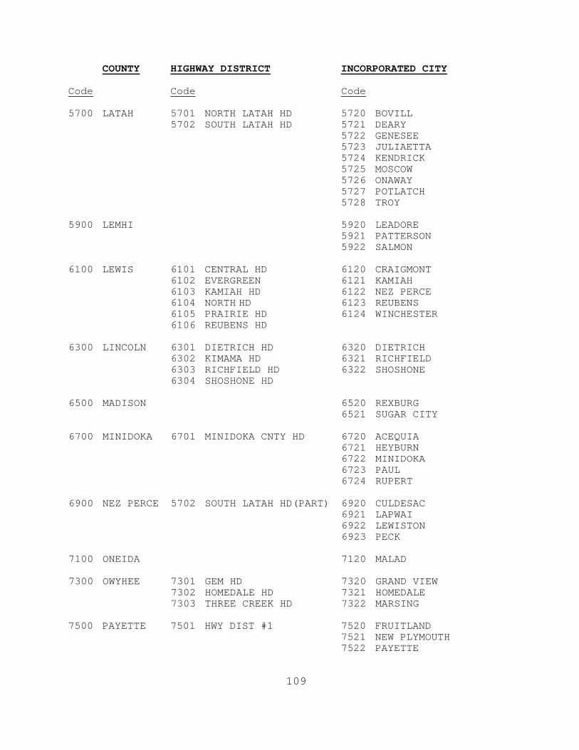
COUNTY HIGHWAY DISTRICT INCORPORATED CITY
Code Code Code 5700 LATAH 5701 NORTH LATAH HD 5720 BOVILL
5702 SOUTH LATAH HD 5721 DEARY 5722 GENESEE 5723 JULIAETTA 5724 KENDRICK 5725 MOSCOW 5726 ONAWAY 5727 POTLATCH 5728 TROY
5900 LEMHI 5920 LEADORE
5921 PATTERSON 5922 SALMON
6100 LEWIS 6101 CENTRAL HD 6120 CRAIGMONT
6102 EVERGREEN 6121 KAMIAH 6103 KAMIAH HD 6122 NEZ PERCE 6104 NORTH HD 6123 REUBENS 6105 PRAIRIE HD 6124 WINCHESTER 6106 REUBENS HD
6300 LINCOLN 6301 DIETRICH HD 6320 DIETRICH
6302 KIMAMA HD 6321 RICHFIELD 6303 RICHFIELD HD 6322 SHOSHONE 6304 SHOSHONE HD
6500 MADISON 6520 REXBURG
6521 SUGAR CITY 6700 MINIDOKA 6701 MINIDOKA CNTY HD 6720 ACEQUIA
6721 HEYBURN 6722 MINIDOKA 6723 PAUL 6724 RUPERT
6900 NEZ PERCE 5702 SOUTH LATAH HD(PART) 6920 CULDESAC
6921 LAPWAI 6922 LEWISTON 6923 PECK
7100 ONEIDA 7120 MALAD 7300 OWYHEE 7301 GEM HD 7320 GRAND VIEW
7302 HOMEDALE HD 7321 HOMEDALE 7303 THREE CREEK HD 7322 MARSING
7500 PAYETTE 7501 HWY DIST #1 7520 FRUITLAND
7521 NEW PLYMOUTH 7522 PAYETTE
109
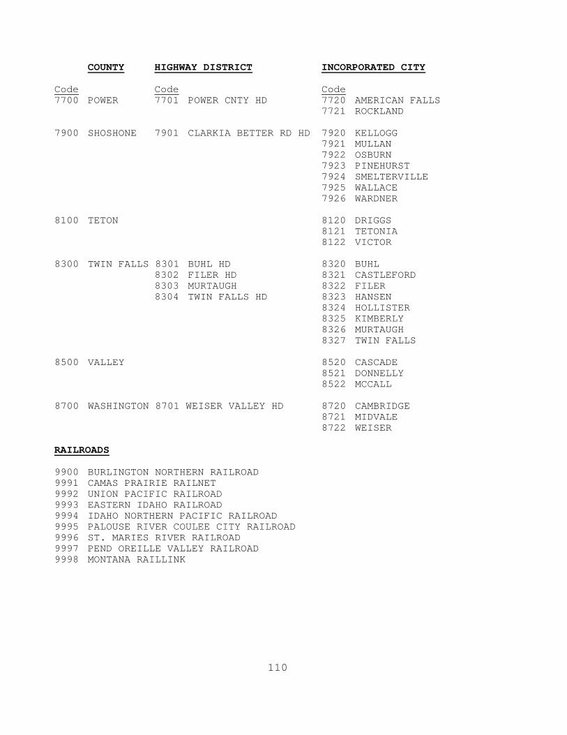
COUNTY HIGHWAY DISTRICT INCORPORATED CITY
Code Code Code 7700 POWER 7701 POWER CNTY HD 7720 AMERICAN FALLS
7721 ROCKLAND 7900 SHOSHONE 7901 CLARKIA BETTER RD HD 7920 KELLOGG
7921 MULLAN 7922 OSBURN 7923 PINEHURST 7924 SMELTERVILLE 7925 WALLACE 7926 WARDNER
8100 TETON 8120 DRIGGS
8121 TETONIA 8122 VICTOR
8300 TWIN FALLS 8301 BUHL HD 8320 BUHL
8302 FILER HD 8321 CASTLEFORD 8303 MURTAUGH 8322 FILER 8304 TWIN FALLS HD 8323 HANSEN
8324 HOLLISTER 8325 KIMBERLY 8326 MURTAUGH 8327 TWIN FALLS
8500 VALLEY 8520 CASCADE
8521 DONNELLY 8522 MCCALL
8700 WASHINGTON 8701 WEISER VALLEY HD 8720 CAMBRIDGE
8721 MIDVALE 8722 WEISER
RAILROADS 9900 BURLINGTON NORTHERN RAILROAD 9991 CAMAS PRAIRIE RAILNET 9992 UNION PACIFIC RAILROAD 9993 EASTERN IDAHO RAILROAD 9994 IDAHO NORTHERN PACIFIC RAILROAD 9995 PALOUSE RIVER COULEE CITY RAILROAD 9996 ST. MARIES RIVER RAILROAD 9997 PEND OREILLE VALLEY RAILROAD 9998 MONTANA RAILLINK
110

BRIDGE DRAWING NUMBER 6 DIGIT FIELD Code a six-digit field (right justified) using the smallest drawing number. If drawing numbers are not available, leave field blank. Do not code preceding zeros. EXAMPLES: Code
Drawing No. 14868 14868 Drawing No. 10 10 Drawing No. R 623A R-623A
PROJECT KEY NUMBER 5 DIGIT FIELD Code a five-digit number (right justified) to indicate the project key number. If there are two or more key numbers due to reconstruction by widening, use smallest key number. If key number is not available leave blank. EQUIPMENT REQUIRED 1 DIGIT FIELD Code a one-digit field to indicate equipment required to inspect the bridge
A - SPECIAL EQUIPMENT (i.e. ladder, canary, dye penetrant, lift truck, crash truck, etc.)
B - BOAT C - A & B N - NONE X - EXTRA PERSON REQUESTED TO PERFORM INSPECTION
INSPECTION AREA 4 DIGIT FIELD Code a four-digit field to indicate the inspection area. State inspectors code District number with 3 preceding zeros. Consultants code area number as assigned on your contract.
111


DIETRICHSHOSHONE
RICHFIELD
HOLLISTER
MURTAUGH
CASTLEFORD HANSENKIMBERLYTWINFALLS
FILER
BUHL
HAZELTONEDEN
JEROME
WENDELLHAGERMAN
BLISS GOODING
LOSTRIVER
MACKAY
STANLEY
CLAYTON
CHALLIS
LEADORE
SALMON
OAKLEY
MALTA
ALBION
DECLO
BURLEY
FAIRFIELD
BUTTECITY
ARCO
MOORE
CAREY
BELLEVUE
HAILEY
SUNVALLEY
KETCHUM
BURLEY
PAUL
RUPERT
ACEQUIA
MINIDOKA
GLENNS FERRY
MOUNTAINHOME
WEISER
MIDVALE
CAMBRIDGE
CASCADE
DONNELLY
MCCALL
MULLANWALLACE
OSBURN
KELLOGG
PINEHURST
SMELTERVILLE
NEWPLYMOUTH
FRUITLAND
PAYETTE
CULDESAC
LEWISTON
LAPWAI
PECK
GRAND VIEW
MARSING
HOMEDALE
EMMETT
WEIPPE
OROFINO PIERCE
ELKRIVER
MELBA
NAMPA
CALDWELL
WILDER GREENLEAF
MIDDLETONNOTUS
PARMA
NEZPERCEWINCHESTER
CRAIGMONT
REUBENS
BONNERSFERRY
MOYIESPRINGS
GENESEE JULIAETTA
KENDRICK
MOSCOW
TROY
DEARY
BOVILL
ONAWAYPOTLATCH
CLARKFORK
OLDTOWN
PRIESTRIVER
EAST HOPE
HOPE
DOVER
SANDPOINT
PONDERAY
KOOTENAI
IDAHOCITY
HORSESHOE BEND
PLACERVILLE
CROUCH
TENSED
ST MARIES
PLUMMER
RIGGINS
WHITE BIRD
GRANGEVILLE
COTTONWOOD
STITES
KOOSKIA
FERDINAND
KAMIAH
COUNCIL
NEWMEADOWS
WORLEY
HARRISON
FERNANLAKE
COEURD'ALENE
STATELINE
POSTFALLS
HAUSERHAYDEN
LAKE
HAYDEN
RATHDRUM
ATHOL
SPIRITLAKE
KUNA
BOISE
MERIDIAN
GARDENCITY
EAGLESTAR
NEWDALE
TETON
PARKER
ST ANTHONY
DRUMMOND
ASHTON
WARM RIVER
ISLANDPARK
DUBOIS
SPENCER
VICTOR
DRIGGS
TETONIA
GRACE
SODASPRINGS
BANCROFT
ROCKLAND
AMERICAN FALLS
IRWIN
SWANVALLEY
AMMON
IDAHOFALLS
IONA
UCON
RIRIE
ABERDEEN
BLACKFOOT
FIRTH
BASALT
SHELLEY
ATOMICCITY
MALAD
ST CHARLES
BLOOMINGTON
PARIS
MONTPELIER
GEORGETOWN
DOWNEY
ARIMO
LAVA HOTSPRINGS
MCCAMMON
INKOM
POCATELLO
CHUBBUCK
REXBURG
SUGAR CITY
RIRIE
RIGBYLEWISVILLE
ROBERTS
MENAN
MUDLAKE
HAMER
FRANKLIN
WESTON
PRESTON
DAYTON
CLIFTON
OXFORD
HEYBURN
Blaine
Butte
Custer
Franklin
Oneida
BearLake
Cassia
Jerome
TwinFalls
Caribou
Bannock
Power
Minidoka
Lincoln
Gooding
Bonneville
Bingham
Owyhee
Camas
Madison
Ada
TetonCanyon Jefferson
Elmore
Payette
Boise
Clark
Gem
Fremont
Washington
Valley
Adams
Lemhi
Lewis
Idaho
NezPerce
Clearwater
Latah
Benewah
Kootenai
Shoshone
Bonner
Boundary³±52
³±128
³±3
³±87
³±75
³±75
³±43
³±32
³±47
³±29
³±28
³±28
³±28
³±22
³±22
³±33 ³±33
³±33 ³±33
³±33
³±33
³±33
³±31
³±48
³±39
³±39
³±61
³±34
³±78
³±78
³±45
³±21
³±21
³±19
³±69
³±19
³±44
³±16
³±52
³±52
³±71
³±55
³±55
³±55
³±55
³±14
³±13
³±13
³±162
³±64
³±62
³±11
³±7
³±7
³±99
³±8 ³±8 ³±8
³±66 ³±9
³±6
³±6
³±6
³±3
³±3
³±3
³±3
³±3
³±60
³±5
³±58
³±97
³±4
³±41
³±53
³±53
³±54³±54
³±41
³±200
³±57
³±1
³±34
³±40
³±36
³±36
³±38
³±37
³±75
³±75
³±81³±77
³±24
³±24
³±27
³±50
³±25³±25
³±74
³±79
³±46
³±46
³±78
³±78
³±51
³±51
³±51
³±51³±67
£¤20
£¤30
£¤12
£¤20
£¤89
£¤89
£¤89
£¤91
£¤91
£¤26
£¤26
£¤26
£¤26
£¤26
£¤26
£¤26
£¤26
£¤26
£¤26
£¤20
£¤20
£¤20
£¤20
£¤20£¤20
£¤20
£¤30
£¤30
£¤30
£¤30
£¤30
£¤30
£¤30
£¤30
£¤30
£¤95
£¤12£¤12
£¤12
£¤95
£¤2
£¤2
£¤2
£¤95
£¤95
£¤95
£¤95
£¤95
£¤95
£¤95
£¤95
£¤95
£¤95
£¤95
£¤95
£¤93
£¤93
£¤93
£¤93
£¤93
£¤93
£¤93
§̈¦86
§̈¦86
§̈¦15
§̈¦15
§̈¦15
§̈¦15
§̈¦15
§̈¦90
§̈¦90
§̈¦84
§̈¦84
§̈¦84
§̈¦84
§̈¦84
§̈¦84
116
IC 119 IC 307IC 308
IC 113
IC 309
IC 118
IC 211IC 208
IC 157
IC 155
IC 173
IC 42
IC 33
IC 38IC 35
IC 36
Ada
Canyon
IC 141
TwinFalls
Gooding
IC 339
IC 346
IC 344
Madison
Fremont
Pilot Project Routesfor increased legal gross weights
Idaho State Highway SystemPilot Project RoutesAllows legal gross weights of up to 129,000 lbs by permit only.Vehicle combinations not to exceed 115 ft overall length includingload overhang. Maximum computed off-track for such combinationsnot to exceed 6.50 ft.
Non-Pilot Project RoutesAllows legal gross weights of up to 105,500 lbs.
IC 13
Oneida
IC 33
IC 26IC 27
IC 28
IC 25
IC 29Canyon
IC 95
Elmore
LegendPilot Project Route
Idaho Falls
Nampa
Twin falls
RexburgSt. Anthony
Area
Mountain Home
Shoshone
Caldwell Burley
BlissWendell
Malad
May 2007
rhollora
Line
rhollora
Line