Icom America Inc. TSR - AB4OJ Setting up the Icom PW1 Prerequisites: Using Exciters The exciter’s...
35
PW1 Linear Amplifier Setup / Configuration Icom America Inc. TSR
-
Upload
truongcong -
Category
Documents
-
view
219 -
download
3
Transcript of Icom America Inc. TSR - AB4OJ Setting up the Icom PW1 Prerequisites: Using Exciters The exciter’s...
PW1 Linear Amplifier
Setup / ConfigurationIcom America Inc.
TSR
TSR
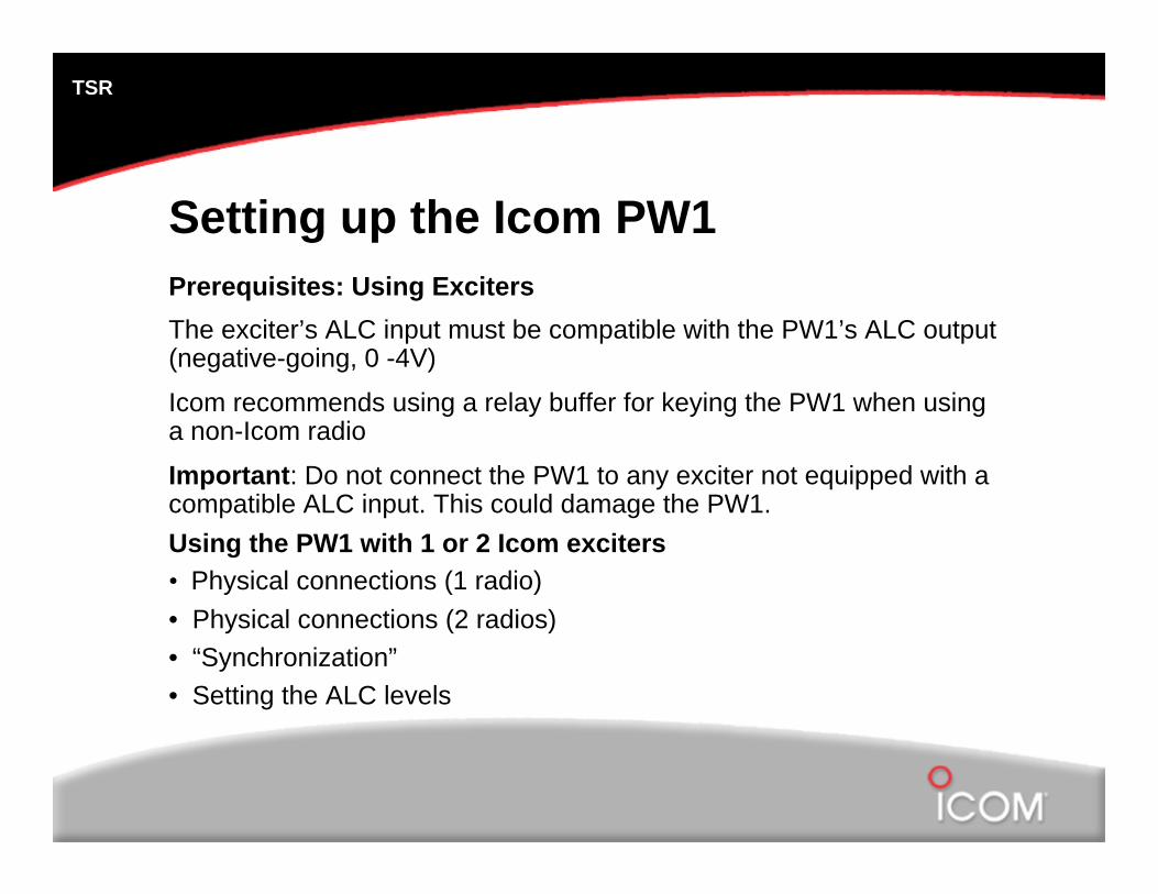
Setting up the Icom PW1Prerequisites: Using ExcitersThe exciter’s ALC input must be compatible with the PW1’s ALC output (negative-going, 0 -4V)
Icom recommends using a relay buffer for keying the PW1 when using a non-Icom radio
Important: Do not connect the PW1 to any exciter not equipped with a compatible ALC input. This could damage the PW1.Using the PW1 with 1 or 2 Icom exciters• Physical connections (1 radio)• Physical connections (2 radios)• “Synchronization”• Setting the ALC levels
TSR
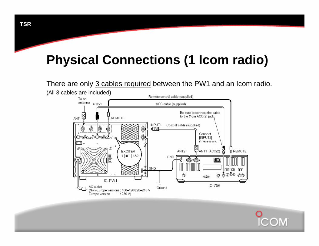
Physical Connections (1 Icom radio)There are only 3 cables required between the PW1 and an Icom radio.(All 3 cables are included)
TSR
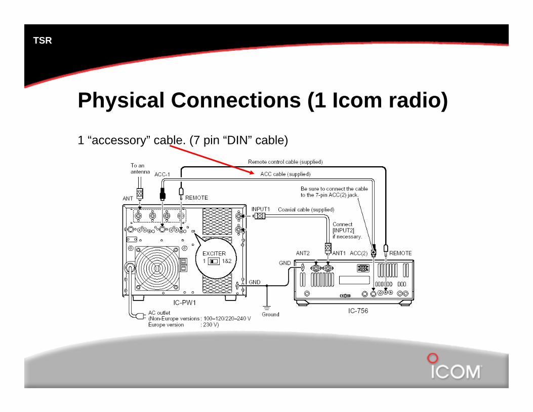
Physical Connections (1 Icom radio)1 “accessory” cable. (7 pin “DIN” cable)
TSR
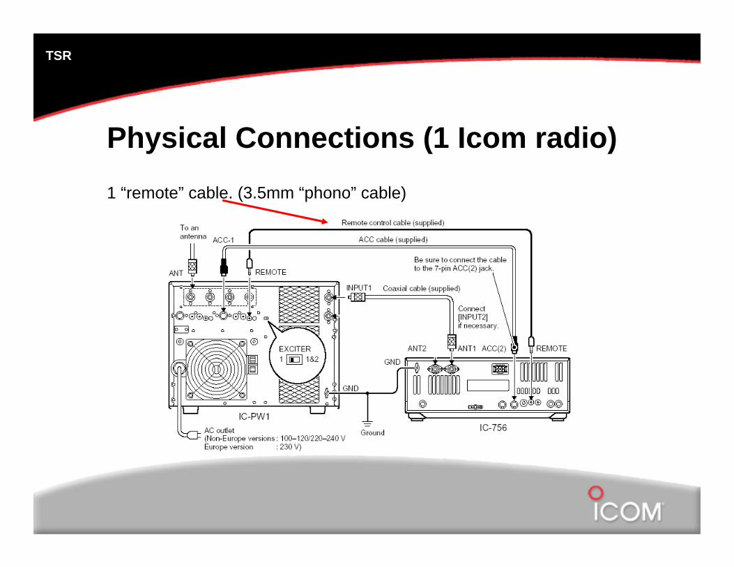
Physical Connections (1 Icom radio)1 “remote” cable. (3.5mm “phono” cable)
TSR
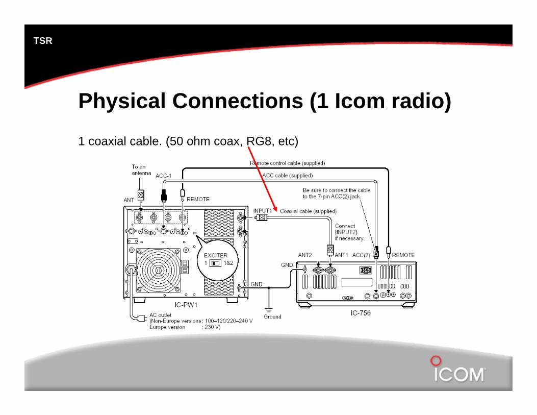
Physical Connections (1 Icom radio)1 coaxial cable. (50 ohm coax, RG8, etc)
TSR
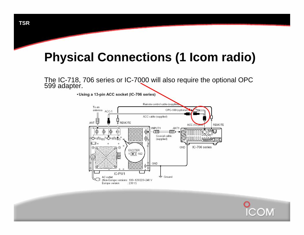
Physical Connections (1 Icom radio)The IC-718, 706 series or IC-7000 will also require the optional OPC 599 adapter.
TSR
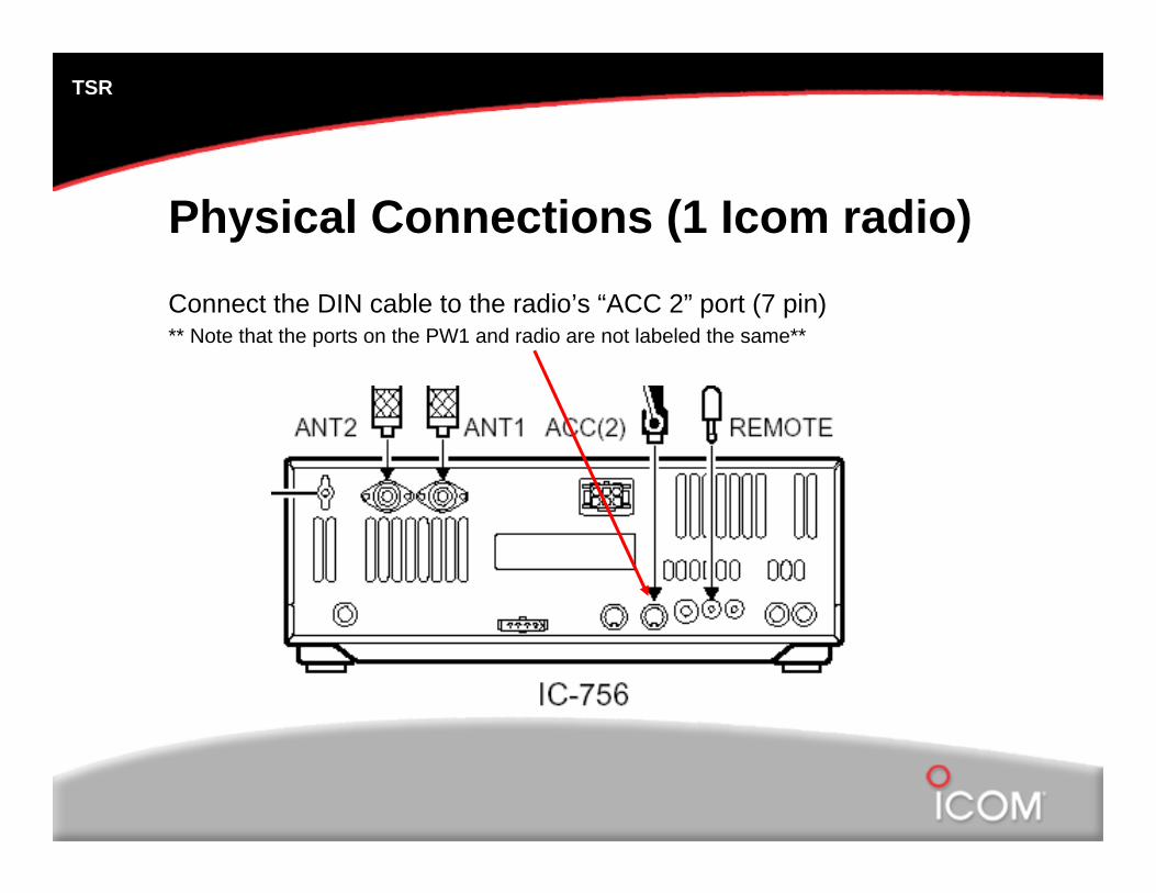
Physical Connections (1 Icom radio)Connect the DIN cable to the radio’s “ACC 2” port (7 pin)** Note that the ports on the PW1 and radio are not labeled the same**
TSR
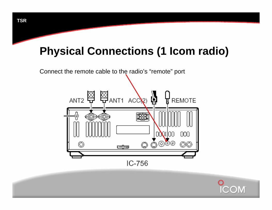
Physical Connections (1 Icom radio)Connect the remote cable to the radio’s “remote” port
TSR
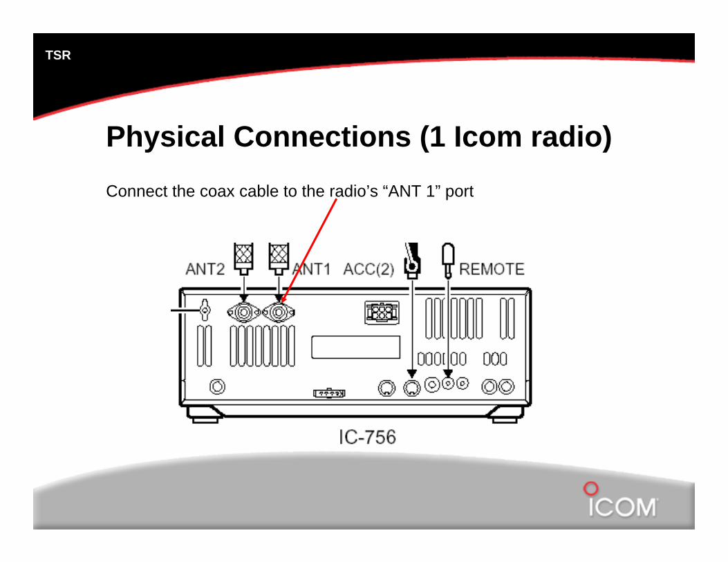
Physical Connections (1 Icom radio)Connect the coax cable to the radio’s “ANT 1” port
TSR
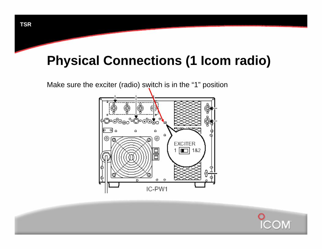
Physical Connections (1 Icom radio)Make sure the exciter (radio) switch is in the “1” position

TSR
Physical Connections (1 Icom radio)Connect the 7 pin DIN cable to “ACC 1” of the PW1
TSR
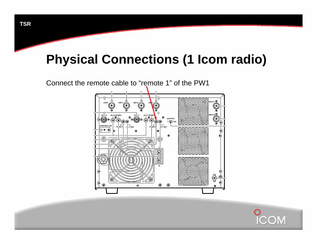
Physical Connections (1 Icom radio)Connect the remote cable to “remote 1” of the PW1
TSR
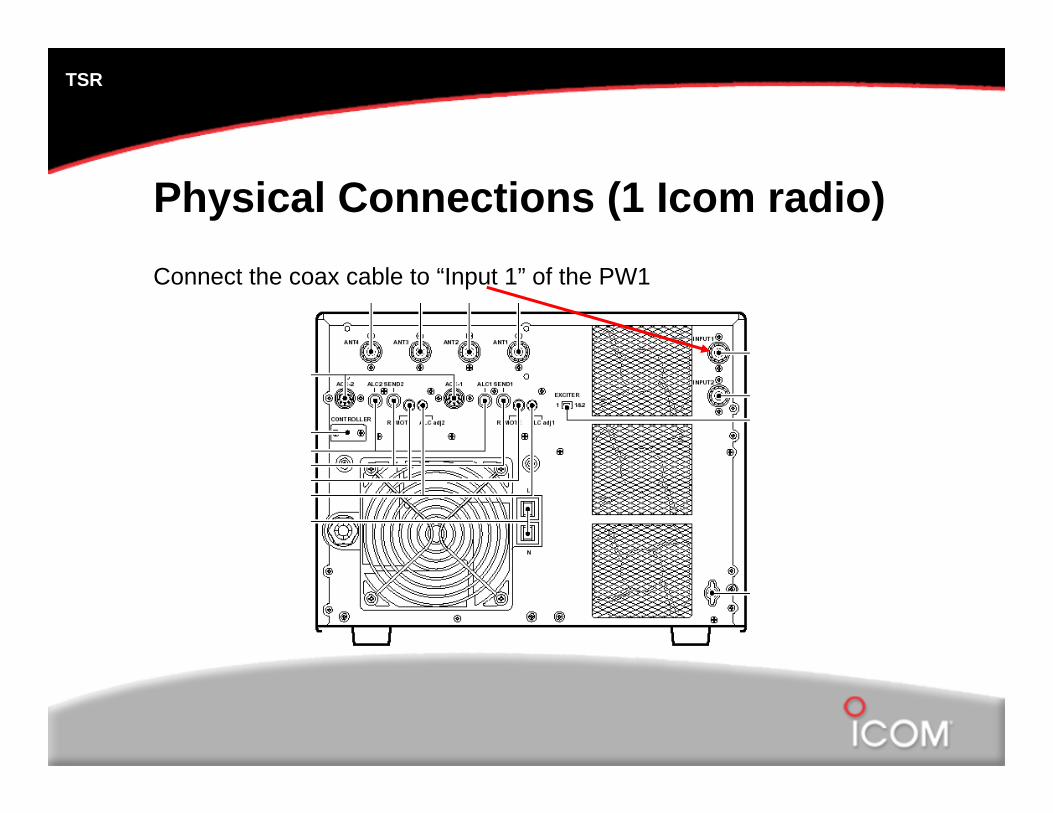
Physical Connections (1 Icom radio)Connect the coax cable to “Input 1” of the PW1
TSR
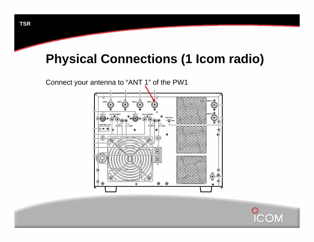
Physical Connections (1 Icom radio)Connect your antenna to “ANT 1” of the PW1
TSR
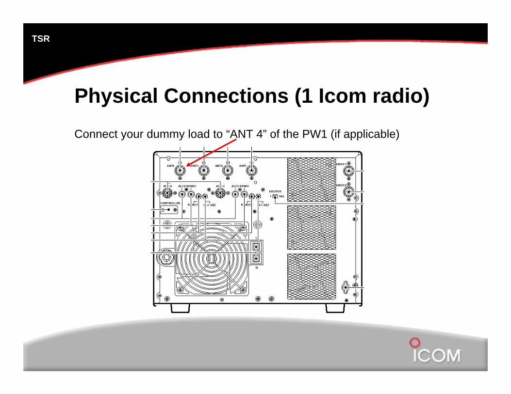
Physical Connections (1 Icom radio)Connect your dummy load to “ANT 4” of the PW1 (if applicable)
TSR
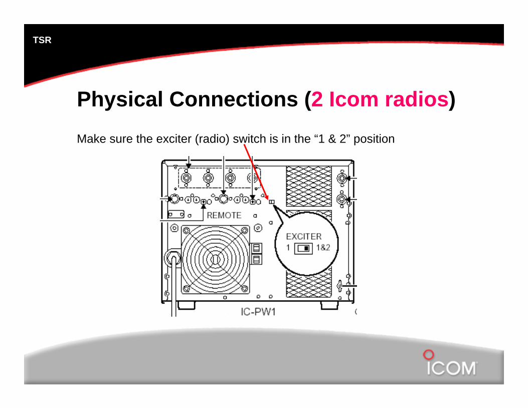
Physical Connections (2 Icom radios)Make sure the exciter (radio) switch is in the “1 & 2” position
TSR
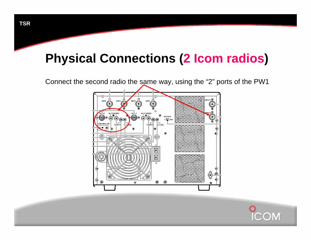
Physical Connections (2 Icom radios)Connect the second radio the same way, using the “2” ports of the PW1
TSR
SynchronizationThe PW1 will automatically change bands, as needed, when the radio frequency is changed.
Synchronization may not be possible with a non-Icom radio.
The synchronization commands are CI-V commands sent from the radio via the remote cable.
Use of a CT-17 is not recommended with the PW1.
TSR
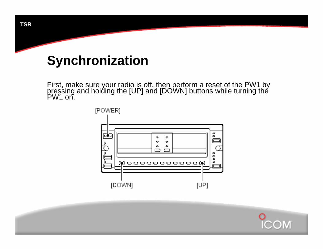
SynchronizationFirst, make sure your radio is off, then perform a reset of the PW1 by pressing and holding the [UP] and [DOWN] buttons while turning the PW1 on.
TSR
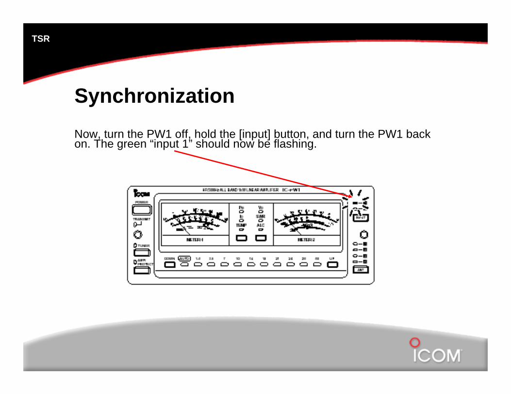
SynchronizationNow, turn the PW1 off, hold the [input] button, and turn the PW1 back on. The green “input 1” should now be flashing.
TSR
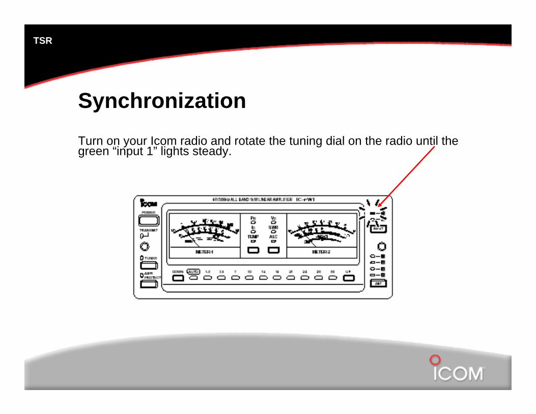
SynchronizationTurn on your Icom radio and rotate the tuning dial on the radio until the green “input 1” lights steady.
TSR
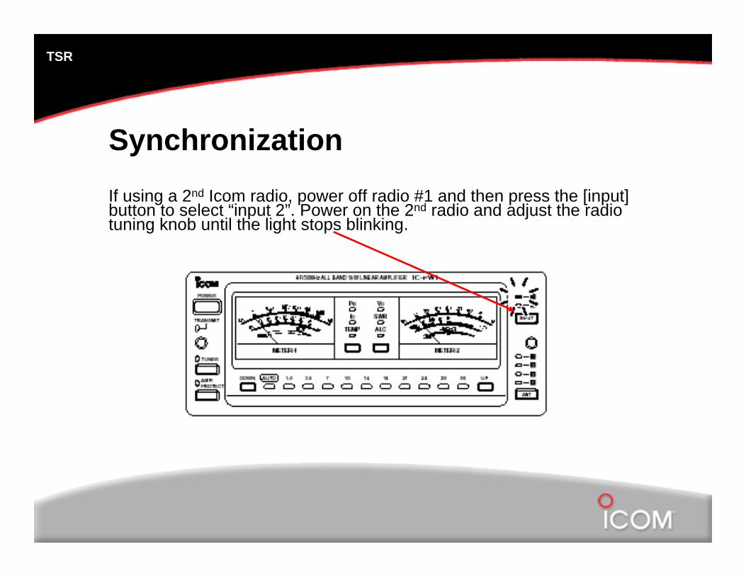
SynchronizationIf using a 2nd Icom radio, power off radio #1 and then press the [input] button to select “input 2”. Power on the 2nd radio and adjust the radio tuning knob until the light stops blinking.
TSR
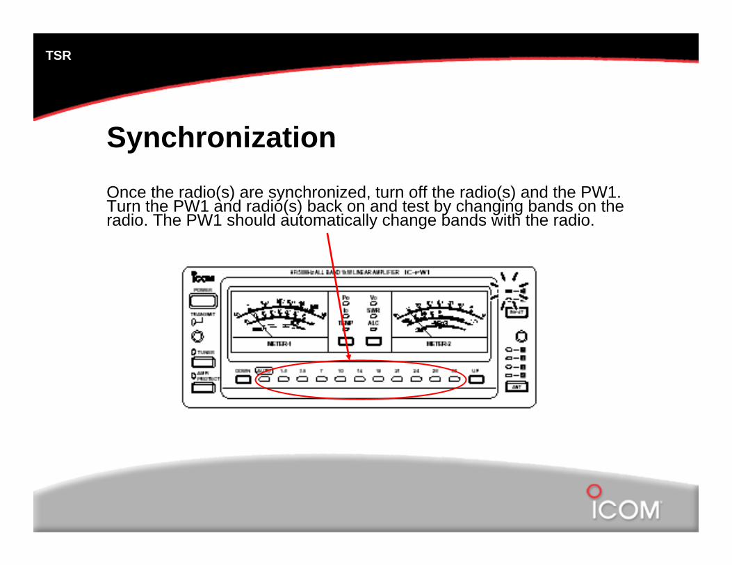
SynchronizationOnce the radio(s) are synchronized, turn off the radio(s) and the PW1. Turn the PW1 and radio(s) back on and test by changing bands on the radio. The PW1 should automatically change bands with the radio.
TSR
Setting ALC LevelsThe final step is to set the ALC levels for the PW1.
The procedure is the same for 1 or 2 Icom radios.
For proper calibration of the PW1, you should use a dummy load. Make sure the load being used is capable of handling the PW1’s output power.
TSR
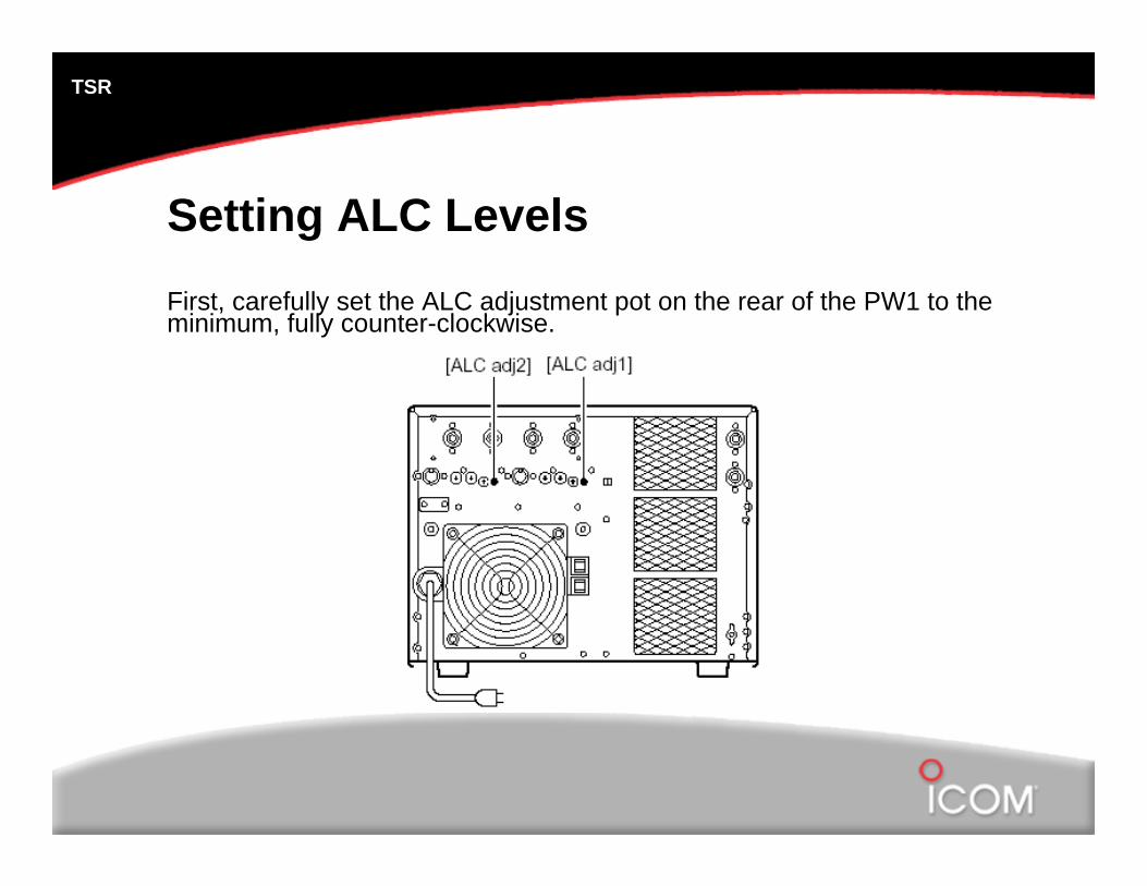
Setting ALC LevelsFirst, carefully set the ALC adjustment pot on the rear of the PW1 to the minimum, fully counter-clockwise.
TSR
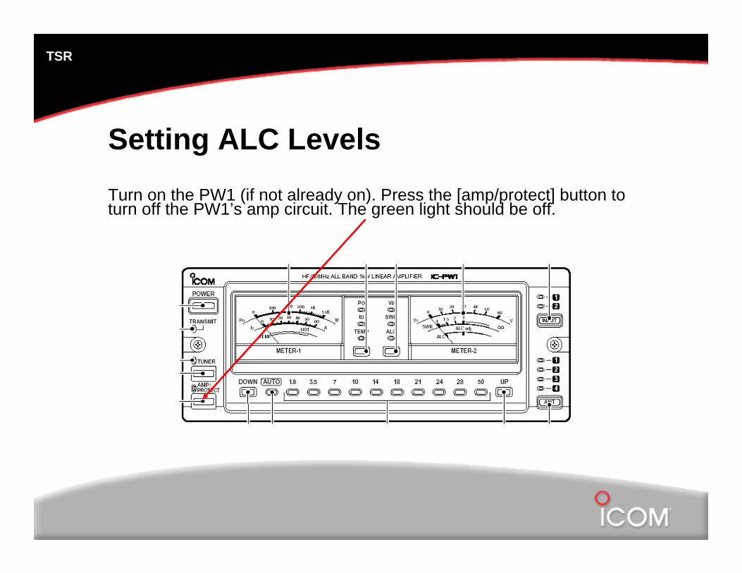
Setting ALC LevelsTurn on the PW1 (if not already on). Press the [amp/protect] button to turn off the PW1’s amp circuit. The green light should be off.
TSR
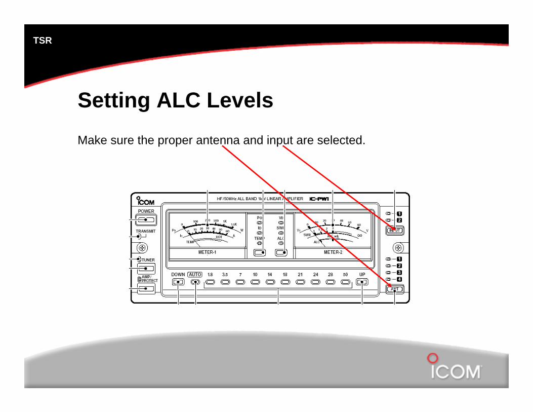
Setting ALC LevelsMake sure the proper antenna and input are selected.
TSR
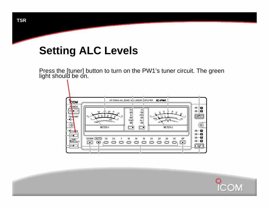
Setting ALC LevelsPress the [tuner] button to turn on the PW1’s tuner circuit. The green light should be on.
TSR
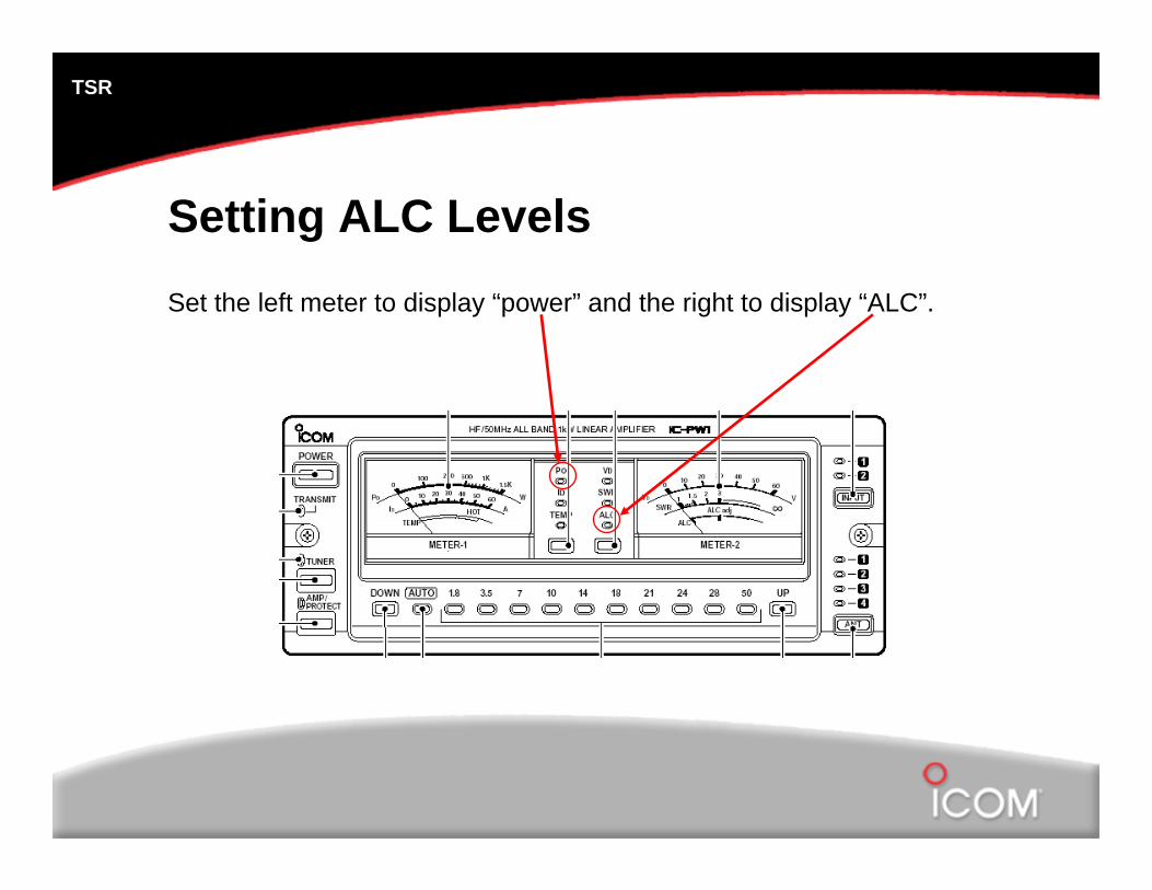
Setting ALC LevelsSet the left meter to display “power” and the right to display “ALC”.
TSR
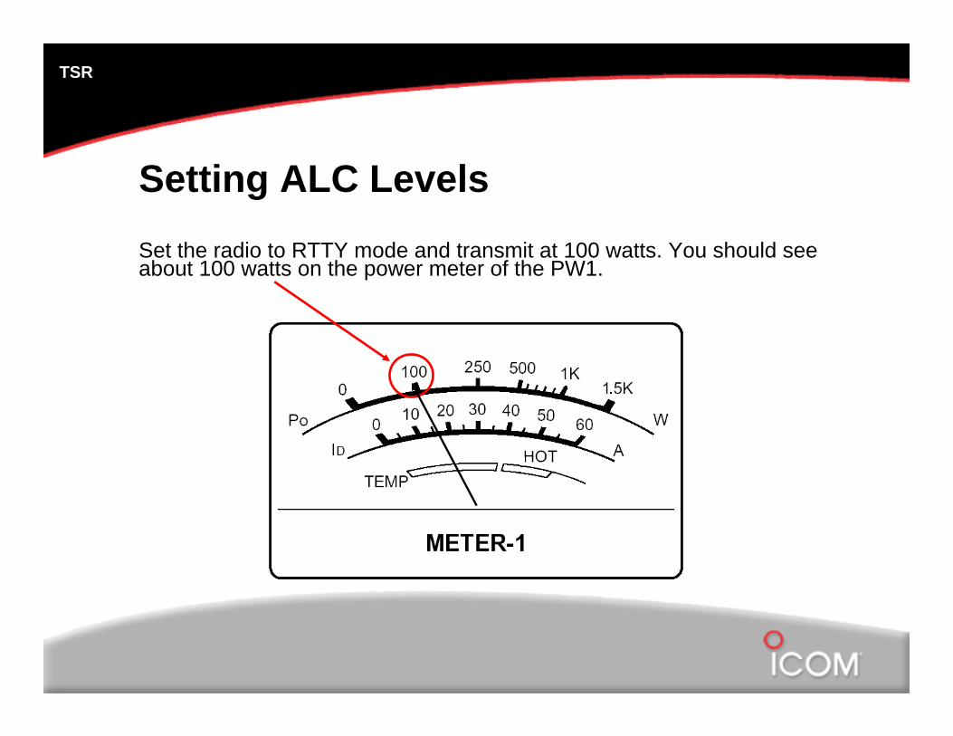
Setting ALC LevelsSet the radio to RTTY mode and transmit at 100 watts. You should see about 100 watts on the power meter of the PW1.
TSR
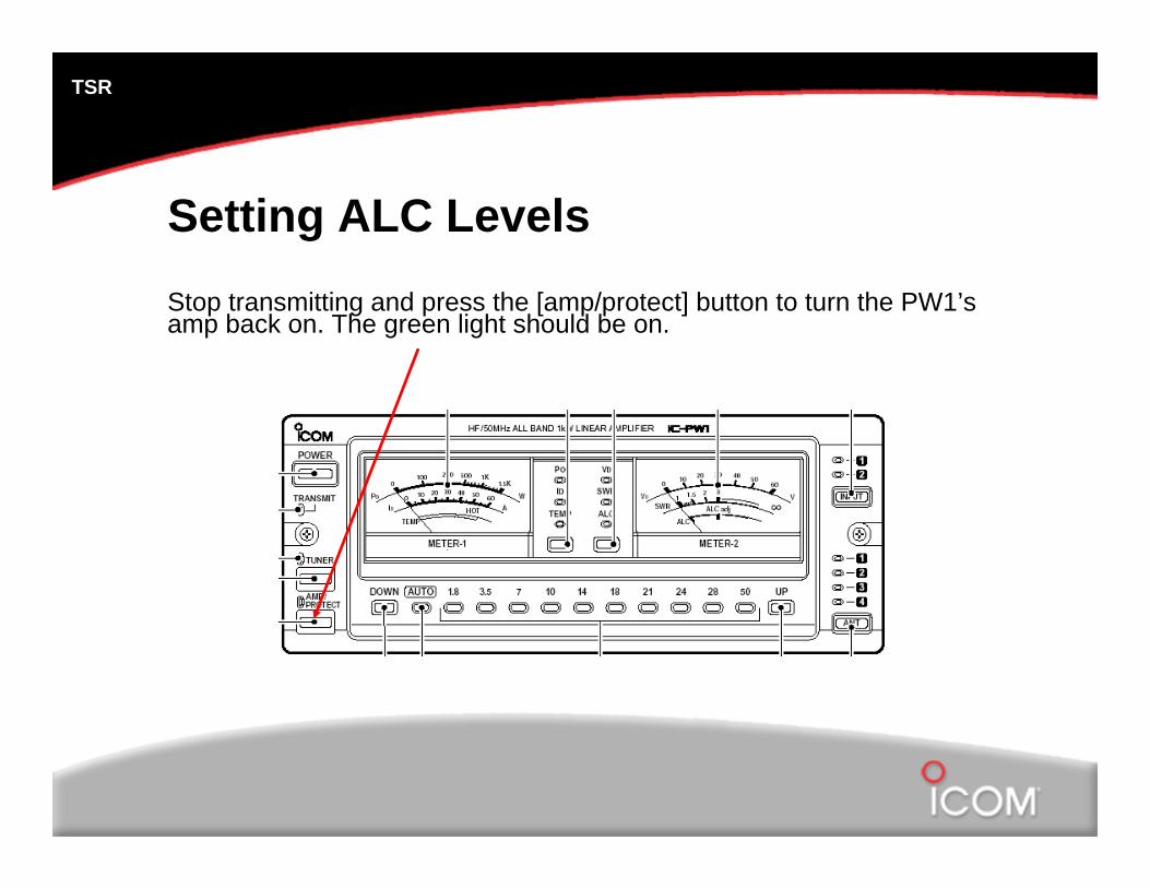
Setting ALC LevelsStop transmitting and press the [amp/protect] button to turn the PW1’s amp back on. The green light should be on.
TSR
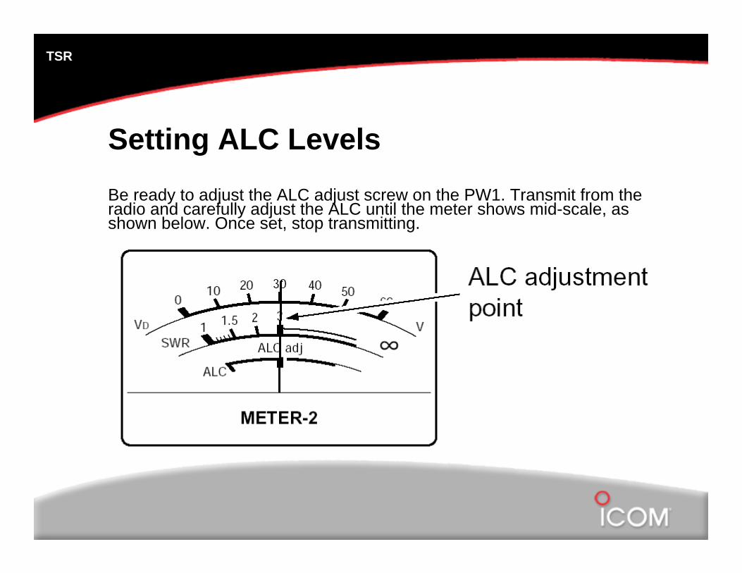
Setting ALC LevelsBe ready to adjust the ALC adjust screw on the PW1. Transmit from the radio and carefully adjust the ALC until the meter shows mid-scale, as shown below. Once set, stop transmitting.
TSR
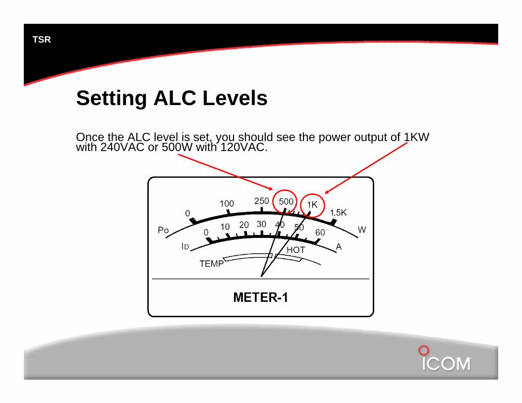
Setting ALC LevelsOnce the ALC level is set, you should see the power output of 1KW with 240VAC or 500W with 120VAC.
TSR
Your PW1 is now ready for use!When watching the radio’s power meter, you will notice that the ALC circuit limits and controls the radio’s power output. You will see about 40-60 watts actual power output from the radio when operating the amp.
©2006 Icom America Inc. The Icom logo is a registered trademark of Icom Inc. All other trademarks remain the property of their respective owners.