
IBM Research Reportdomino.watson.ibm.com/library/cyberdig.nsf/papers/8934585FFADAD4… · Thomas J....
32
RC 22109 (W0107-009) 6 June 2001 Computer Science IBM Research Report An Overview of the Bluetooth Wireless Technology Chatschik Bisdikian IBM Research Division Thomas J. Watson Research Center P.O. Box 704 Yorktown Heights, NY 10598 Research Division Almaden - Austin - Beijing - Haifa - India - T. J. Watson - Tokyo - Zurich LIMITED DISTRIBUTION NOTICE: This report has been submitted for publication outside of IBM and will probably be copyrighted if accepted for publication. It has been issued as a Research Report for early dissemination of its contents. In view of the transfer of copyright to the outside publisher, its distribution outside of IBM prior to publication should be limited to peer communications and specific requests. After outside publication, requests should be filled only by reprints or legally obtained copies of the article (e.g. , payment of royalties). Copies may be requested from IBM T. J. Watson Research Center , P. O. Box 218, Yorktown Heights, NY 10598 USA (email: [email protected]). Some reports are available on the internet at http://domino.watson.ibm.com/library/CyberDig.nsf/home .
Transcript of IBM Research Reportdomino.watson.ibm.com/library/cyberdig.nsf/papers/8934585FFADAD4… · Thomas J....

RC 22109 (W0107-009) 6 June 2001 Computer Science
IBM Research Report
An Overview of the Bluetooth Wireless Technology
Chatschik BisdikianIBM Research Division
Thomas J. Watson Research CenterP.O. Box 704
Yorktown Heights, NY 10598
Research DivisionAlmaden - Austin - Beijing - Haifa - India - T. J. Watson - Tokyo - Zurich
LIMITED DISTRIBUTION NOTICE: This report has been submitted for publication outside of IBM and will probably be copyrighted if accepted for publication. It has been issued as a Research Reportfor early dissemination of its contents. In view of the transfer of copyright to the outside publisher, its distribution outside of IBM prior to publication should be limited to peer communications and specific requests.After outside publication, requests should be filled only by reprints or legally obtained copies of the article (e.g. , payment of royalties). Copies may be requested from IBM T. J. Watson Research Center , P. O. Box 218,Yorktown Heights, NY 10598 USA (email: [email protected]). Some reports are available on the internet at http://domino.watson.ibm.com/library/CyberDig.nsf/home .

An Overview of the BluetoothWireless Technology
Abstract:The Bluetooth wireless technology is designed as a short-range connectivity solutionfor personal, portable and handheld electronic devices. Since, May 1998 theBluetooth SIG steers the development of the technology through the development ofan open industry specification, including both protocols and application scenarios,and a qualification program designed to assure end-user value for Bluetoothproducts. This article highlights the Bluetooth wireless technology.1
1 Any opinions expressed in this article represent only the personal opinions of the author and do not
reflect a position of the author’s employer or any other entity’s.
Chatschik BisdikianIBM Corporation
Thomas J. Watson Research Center30 Saw Mill River RoadHawthorne, NY 10532

Introduction 25 June 2001 2
1 INTRODUCTION
For the last few years, the wireless world has been bombarded daily about a newgeneration of radio frequency (RF) technologies that would have a profound impact, if notrevolutionarize, the way we live and contact our businesses. This new generation oftechnologies spans across the full spectrum of wireless communications coverage. Thirdgeneration (3G) wireless technologies are being developed to enable personal, high-speedinteractive connectivity to wide area networks (WANs). The IEEE 802.11b wireless localarea network (LAN) technology, also referred to as Wi-Fi, finds itself with an increasingrate in corporate and academic office spaces, buildings, and campuses. Furthermore, withslow, but steady rate, the 802.11b technology makes inroads in public areas like airportsand coffee bars.
WAN and LAN technologies enable device connectivity to infrastructure based services,either through a wireless carrier provider or through a campus or corporate backboneintranet. The other end of the coverage spectrum is occupied by the short-range personalwireless connectivity technologies allowing personal devices to communicate with eachother directly without the need of an established infrastructure. The infrared (IR)technology is a widespread example of such a personal connectivity solution. Moving astep further in functionality, the development of the Bluetooth? wireless technologybrings the benefits of the omni-directionality and absence line of sight requirement of RF-based connectivity in the personal connectivity space. The personal connectivity spaceresembles a communications bubble follows people around that empower them to connecttheir personal devices with other devices that enter the bubble. Connectivity in this bubbleis spontaneous and ephemeral and can involve several devices of diverse computingcapabilities; this is unlike wireless LAN solutions that are designed for communication ofdevices of sufficient computing power as well as battery capabilities.
The Bluetooth2 wireless technology3 will serve primarily as a replacement of theinterconnect cables between a variety of personal devices, including notebook computers,cellular phones, personal digital assistants (PDAs), digital cameras, etc. The Bluetoothwireless technology aims in serving as the universal low cost, user friendly, air-interfacethat will replace the plethora of proprietary cables that people need to carry and use toconnect their personal devices. While, typically, personal devices communicate based onthe RS-232 serial port protocol, proprietary connectors and pin arrangements make itimpossible to use the same set of cables to interconnect devices from differentmanufactures, and, some times, even from the same manufacturer. The primary focus ofthe Bluetooth wireless technology is to provide a flexible cable connector withreconfigurable pin arrangements permitting several personal devices to interconnect with
2 Bluetooth is a trademark owned by the Bluetooth SIG, Inc., USA.3 According to the Bluetooth brand requirements document, the term “Bluetooth” must always be used as
an adjective. Furthermore, when the term “Bluetooth” is used to denote the corresponding technology, theterm “wireless” must be inserted between Bluetooth and technology, as in “Bluetooth wireless technology”.The author recognizes that the above rules are not always followed and the term “Bluetooth” has grown torepresent both the technology and the whole industry behind it.

Introduction 25 June 2001 3
each other. Thus, a wireless headset will connect to a cellular phone with the same easethat it will connect to a notebook computer, no matter who manufactures the headset orthe cellular phone or the notebook computer. Similarly, one will be able to connectcomputer peripherals ranging from keyboards and mice to printers and office applianceswithout the worry of having available and utilizing the right interconnect cables.
Another focus of the technology is to enable a uniform interface to data access points foraccessing data services. A user using any number of data capable devices will be able toconnect to a LAN access point that provides access to, say, the corporate intranetinfrastructure and services. Likewise, the user will be able to connect to her cellular phoneand access WAN data services. Applications can then be written that could provide theuser with a similar connectivity experience connecting to data service in either manner.Connecting to data services through one’s cellular phone gives rise to the concept of apersonal gateway. People will carry their personal gateways anyway they go. Thepersonal gateway will serve as a facilitator in accessing remote data services, with theadded convenience that it can be kept hidden, away from the line of sight of itscommunicating Bluetooth partner. The Bluetooth wireless technology enables theunobtrusive separation of the functionality of connecting to a data service from viewingand interacting with the information provided by the data service. Thus, a PDA can beused as a more convenient I/O device for entering and receiving data, while using thepersonal gateway purely for communicating with the wireless data carrier.
Yet another focus item for the Bluetooth wireless technology is to enable ad hocconnectivity among personal devices. This will permit individuals to form collaborativegroups, for example, during a conference meeting, to exchange data without the need torely on an infrastructure to support their communication.
The above focus points have shaped the Bluetooth wireless technology from its outset.Actually, the above focus points have set the development of this technology apart fromother wireless efforts. To guarantee that users will benefit from the technology from theoutset, the Bluetooth specification relates with a set of simple yet useful usage scenarios.In particular, the specification defines the methods by which these usage scenarios shouldbe implemented in various Bluetooth devices. The definitions of these methods, referredto as profiles, provide the guidelines according to which a selected set of applicationsenabled by the Bluetooth wireless technology can be developed in an interoperablefashion. We will discuss about the Bluetooth specification and its profiles in laterchapters.
Incidentally, the name Bluetooth comes from the Danish king Harald Blåtand(Bluetooth). King Bluetooth is credited for uniting the Scandinavian people during the10th century. Similarly, the Bluetooth wireless technology aims in uniting personalcomputing devices. The name was chosen temporarily to describe the yet unannounceddevelopment project. However, the search for a new name never came to a successfulfruition and the temporary name became permanent. In retrospect, the selection of thisjoyful name can be credited about as much as the potentials of the Bluetooth wireless

The History of the Bluetooth Wireless Technology25 June 2001 4
technology it represents for the recognition and acceptance the technology has received sofar.
This paper is organized as follows. In chapter 2……
2 THE HISTORY OF THE BLUETOOTH WIRELESS TECHNOLOGY
During the first half of 1990s, radio engineers had come to the realization that thetechnology trends are such that low cost, low power, short-range radios will be possible inthe near future. These low cost radios will serve as cable replacements between personaldevices and primarily cellular phones and other personal data terminals like computernotebooks. A team of engineers from Ericsson, embarked in developing such a radiotechnology.
However, for these radios to be of value to the cellular phones that they will attach to,other personal communicating companion devices are needed that will be using the sameradio technology and the same upper layer communications protocols to communicatewith. In other words, for this new technology to be successful, multiple devices frommultiple manufacturers need to incorporate it and interoperate with each other. Therefore,a widely acceptable standard needs to be developed for this technology. The need for anindustry standard is further underscored by the strong relation of this technology withconsumer products and the requirement of the consumer market for low cost and ease touse, interoperable devices.
The development of the Bluetooth industry standard started late in the winter of 1998when Ericsson, IBM, Intel, Nokia, and Toshiba formed the Bluetooth Special IndustryGroup (SIG) to develop and promote a global solution for short-range wirelesscommunication operating in the unlicensed 2.4 GHz ISM (industrial, scientific, medical)band. The SIG comprises several working groups including a program managementgroup, which currently comprises a board of directors, that sets-up the directions andoversees the activities of the SIG. There is a marketing team that not only orchestrated thepromotion of the technology in the market, but guided and steered its development tosatisfy important usage scenarios. There are technical working groups that are responsiblefor the development and maintenance of the Bluetooth industry specification. There is aregulatory group to interface with authorities responsible with regulating the usage ofradio frequencies in various countries. There is a legal group that deals, among otherthings, with issues related to the management of the IP (intellectual property) associatedwith the technology, and a number of other groups.
To facilitate the wide acceptance of this new technology, the SIG decided to avail all thetechnologies explicitly included in the Bluetooth specification royalty-free to adoptermembers of the technology. In other words, any adopter of the Bluetooth wirelesstechnology can build Bluetooth components and products sharing for free with other

The History of the Bluetooth Wireless Technology25 June 2001 5
adopter companies any IP (intellectual property) included in the Bluetooth specification. 4
The SIG announced its existence and intentions to the public in May 1998 joined, at thetime, by about 70 adopter members; as of this writing there are about 2,500 adoptermembers. A little over a year later, in the summer of 1999, the over 1,600-page Bluetoothspecification version 1.0A became publicly available. The Bluetooth specification wasdeveloped by the five promoter (founding) members with substantial contributions fromtwo additional companies, 3Com and Motorola. Adopter members have the opportunity toexamine early versions of the Bluetooth specifications and provide feedback as needed.Due to the Bluetooth SIG license agreement, the development of the specification is notmade available to the general public until it is finished and approved by the BluetoothSIG. Adopter members have the privilege to look at the specification prior to its publicavailability.
The Bluetooth specification ver. 1.0A comprised the following two parts, which weelaborate more later in the paper:
? The core specification defining the radio characteristics and the communicationprotocols for exchanging data between devices over Bluetooth radio links.
? The profile specification that defines how the Bluetooth protocols are to be used torealize a number of selected applications.
In December 1999, the promoter group increased from five to nine with the addition of:3Com, Lucent, Microsoft, and Motorola. As of early 2001, Agere, a Lucent spin-offcomprising its former microelectronics division, has taken the place of Lucent in thepromoters group.
As developers started to build early prototypes and later on products based on thespecification, the SIG started collecting comments and suggestions from the developersthat were requesting clarifications on the specification. The SIG released additionalversions of the specification incorporating, in the form of errata, several of the commentsreceived directly from the developers or indirectly though a series of informalinteroperability testing gatherings, referred to as unplug fests. During an unplug fest,developers have the opportunity to test their Bluetooth implementations against those ofother developers and iron out possible discrepancies among them.
Table 1 highlights some key dates in the history of the Bluetooth wireless technology andits specification.
Mid ‘90s Early seeds of the Bluetooth radio technology.
Feb’98 The Bluetooth SIG is formed by the five promoter companies.
4 Because there are currently several generations of the Bluetooth specification, there are several
generations of adopters agreements as well. Thus, certain companies that had signed only the early adoptersagreement(s) have free access only to the IP in the early generation(s) of the specification as well.

The Core Specification 25 June 2001 6
March’98 First face-to-face technical meeting of the software task force. The “hardware” taskforce, called the air group, has been meeting prior to the formation of the SIG.
May’98 The SIG announced publicly its existence and its objectives.
Oct’98 The first Bluetooth Developers Conference takes place in Atlanta, GA, USA.
July’99 The Bluetooth spec. ver. 1.0A is release to the general public.
July’99 The Bluetooth SIG submits a proposal to the newly formed IEEE 802.15 workinggroup on wireless personal area networks.
Dec’99 The promoter group increases to nine.
Dec’99 The Bluetooth spec. ver. 1.0B is release to the general public.
Jan’00 New working groups start to be formed to develop additional Bluetooth specifications
Feb’01 The Bluetooth SIG is incorporated in the Bluetooth SIG, Inc.
Feb’01 The Bluetooth spec. ver. 1.1 is release to the general public.
Table 1: A Bluetooth chronology
As mentioned earlier, the Bluetooth specification comprises over 1,600 pages of protocoland application specifications. It contains a core specification part, which comprises thecommunications protocols, the testing protocols and procedures, and the compliancerequirements. It also contains a profile specification part that comprises application andprotocol guidelines for building a selected set of interoperable applications. In thefollowing two chapters we present these two parts of the Bluetooth specification, startingwith the core specification.
Note that the Bluetooth specification has been written primarily as an implementationmanual rather than a formal communications standard document. This aspect of thespecification reflects its development process by a group of engineers that actuallydeveloped the technology in parallel to the development of the specification. Theseengineers expressed in the specification their experiences stemmed by theirimplementations in a prose rather than using strict language formalisms commonly foundin a formally developed standard. This approach had its pros and cons. On the upside, thespecification is easier to read that a formal standards document. On the downside, usingprose, which is naturally imprecise, the specification is open to conflicting interpretation,which are resolved through an errata process.
3 THE CORE SPECIFICATION
The Bluetooth core specification contains both a hardware and a software description. Theformer pertains to the lowest layers of the protocol stack, like the radio and the baseband,while the latter pertains to higher layers that are typically executed by dedicatedmicroprocessors and/or the processor of a host device.

The Core Specification 25 June 2001 7
Figure 1 depicts the Bluetooth protocol stack, which also shows the application andprofiles “layer” for completeness. The protocols in the stack have been grouped in twocategories: the transport and the middleware protocols. The transport protocols compriseprotocols developed exclusively for the Bluetooth wireless technology. These protocolsare involved in all data communications between two Bluetooth devices. The middlewareprotocols comprise both Bluetooth specific protocols and other adopted protocols. Theseprotocols are used selectively to enable different applications, including both legacy andnew applications, to exchange data using the Bluetooth wireless technology. Wheneverdesired, the middleware protocols shield these applications from the specifics of theBluetooth transport protocols.
Radio
Baseband
Link Manager
L2CAP
TCSRFCOMM SDP
Applications/Profiles
transportprotocols
middlewareprotocols
HCI
Other
C_PA_P
HCI: host controller interfaceA_P: audio pathC_P: control path
Figure 1: The Bluetooth protocol stack
This grouping of the protocols in the Bluetooth protocol stack is not part of thespecification. Rather, it is used here as a natural grouping of the protocols for ease ofpresentation.
3.1 The transport protocols
3.1.1 The radio
The radio layer defines the technical characteristics of the Bluetooth radios. A Bluetoothradio operates on the license-free 2.4 GHz ISM band and is compliant to FCC part 15regulations for intentional radiators in this band. It employs a fast (1,600 hops/sec),frequency hoping, spread-spectrum (FHSS) technique. The radio hops in a pseudo-random

The Core Specification 25 June 2001 8
fashion on 79 one-megahertz channels.5 The frequencies are located at (2,402+k) MHz,k=0, 1, …, 78.
The modulation technique is a binary Gaussian frequency shift-keying (GFSK) and thebaud rate is 1 Msymbols/sec. Hence, the bit time is 1 ? sec and the raw transmission speedis 1 Mb/sec. The Bluetooth radios come in three power classes depending on their transmitpower. Class 1 radios have transmit power of 20 dBm (100 mW); class 2 radios havetransmit power of 4 dBm (2.5 mW); and class 3 radios have transmit power of only 0 dBm(1 mW). Due to the power and cost constraints of the various personal devices to useBluetooth radios, the 0 dBm radios are expected to be the ones mostly used in thesedevices.
3.1.2 The baseband
The baseband defines the key procedures that enable devices to communicate with eachother using the Bluetooth wireless technology. The baseband defines the Bluetoothpiconets and how they are created, and the Bluetooth links. It also defines how thetransmit resources are to be shared among several devices in a piconent as well as the low-level packet types.
3.1.2.1 The Bluetooth address and clock
Each Bluetooth device has two parameters that are involved in practically all aspects ofBluetooth communications. The first one is a unique IEEE-type 48-bit address assigned toeach Bluetooth radio at manufacture time. The Bluetooth device address (BD_ADDR) isengraved on the Bluetooth hardware and it cannot be modified. The second parameter is afree running 28-bit clock that ticks once every 312.5 ? sec, which corresponds to half theresidence time in a frequency when the radio hops at the nominal rate of 1,600 hops/sec.
Bluetooth devices can communicate with each other, by acquiring each other’s Bluetoothaddresses and clocks, as will further be described in the sequel.
3.1.2.2 The Bluetooth piconet
A piconet is a collection of Bluetooth devices that can communicate with each other. Apiconet is formed in an ad hoc manner without any infrastructure assistance and it last foras long as the creator of it needs and is available to communicate with other devices. Apiconet contains at least one device identified as the master of the piconet and at most 7other devices identified as slaves with which the master is actively involved incommunications. The terms master and slave are relative to a particular existing piconet.The terms are not assigned to the radio units at manufacture time. A Bluetooth radio mayserve either as a master or slave at different times.
5 The specification permits a reduced channel hop over only 23 channels for countries that have
restrictions in their corresponding ISM band.

The Core Specification 25 June 2001 9
To identify each slave, the master of a piconet assigns the slaves participating in activecommunications in the piconet a locally unique active member address (AM_ADDR). Themaster regulates and controls who and when transmits. While up to 7 slaves may beactively communicating in a piconet at a time, additional devices may be registered withthe master and be invited to become active whenever necessary. These additional devicesare called parked. Bluetooth devices not associated with any piconet are in stand-by mode.Figure DDD shows two piconets with a number of slaves and parked devices associatedwith them, and a few stand-by devices. Bluetooth piconets can coexist in time and spaceindependently of each other. Furthermore a single device may be a member of severalpiconets, a case refer to as scatternet in the Bluetooth parlance.
M: masterS: slaveP: parkedSb: stand-by
S
M
M
S
S
S
S
S
P
P
Sb
Sb
Sb
radius ofcoverage
Figure DDD: Bluetooth piconets
The communications channel in a piconet is defined as the sequence of the frequency hopsfollowed by the piconet members in a synchronized manner. The transmit and receivetime axis are slotted, with each slot lasting the duration of a nominal frequency hop, 625? sec. Each baseband transmission resides fully within the boundaries of a slot. However,multi-slot packets occupying three or five slots, instead, are also allowed. During thetransmission of a multi-slot packet, the transmit frequency does not change. When hopingresumes, it resumes with the frequency whose turn would have been if the devices were touse only single-slot transmissions.
To maintain time synchronization for the hops, slaves utilize the Bluetooth clock of themaster and the fact that hops occur in multiples of 625 ? sec; slaves actually maintain theoffset time between their Bluetooth clock and that of their master. Slots in a piconet areidentified as even or odd according to the value of the second least significant bit of the

The Core Specification 25 June 2001 10
Bluetooth clock of the master; recall that the Bluetooth clock ticks at a rate twice that ofthe slot rate. To recreate the frequency hop sequence in a piconet, a slave utilizes theBluetooth address of the master of the piconet. Furthermore, the Bluetooth clock of themaster identifies the particular frequency to be used at a particular slot. Therefore, thecommunications channel in a piconet is fully identified by the master. As a result, in thecase of scatternets, a device can serve as a master for only one piconet for otherwise thetwo piconets cannot be distinguished from each other.
The master and the slaves alternate transmit opportunities in a time-division duplex (TDD)fashion. In particular, the master transmits on even numbered slots, as defined by themaster’s Bluetooth clock, while the slaves transmit on odd numbered slots; recall thateach slot lasts 625 ? sec. A slave can transmit only if the master has just transmitted to thisslave. A transmission may last one, three, or five slots; however, the specification requiresthat only the one-slot transmissions be mandatory. In the case of scatternets, a devicecannot receive or transmit data simultaneously in two or more piconets. However, such adevice may time-share its participation in each piconet over non-overlapping timeintervals.
To engage in communications in a piconet, the slaves in the piconet need to know theBD_ADDR and Bluetooth clock of the master. Likewise the master needs to know theidentities of the slaves. How this is done, i.e., how a piconet is formed is highlighted next.
3.1.2.3 The piconet creation
The creation of a piconet is a two-step process, depending on whether the master of thepiconet knows the identity, BD_ADDR, of the device it wants to communicate with. Thisprocess comprises an inquiry phase, for locating devices, and a paging phase, for invitingspecific devices to join a piconet.
The inquiry process is a device discovery process during which the master of a futurepiconet discovers other devices in its vicinity. The master makes its presence know bytransmitting inquiry messages. Devices that perform inquiry scan, i.e., search actively forinquiry messages, respond with inquiry response messages that, among other things,contain the BD_ADDR of the device.

The Core Specification 25 June 2001 11
IS
Inq
IS
IS
Sb
Sb
radius ofcoverage
Sb
Sb
Inq: inquiring deviceIS: inquiry scanning deviceSb: stand-by
anybody there?
anybody there?
me(BD_ADDR:1)
me(BD_ADDR:2)
me(BD_ADDR:N)
(1)
(1’)
(2)
(2’)
(2*)
Figure hjk: The inquiry steps
Figure hjk outlines the inquiry process. An inquiring device (Inq) transmits inquirymessages: transmissions (1), (1’), etc. These transmissions are made over a well-definedperiodic inquiry frequency hoping sequence with period 32 hops. The inquiry frequencyhoping sequence is reserved just for the inquiry process. Devices, IS, may actively searchfor inquiries by scanning for transmissions over the inquiry frequency hoping sequence.Following a receipt of an inquiry message, an inquiry scanning device returns an inquiryresponse message containing, among other things, the device’s BD_ADDR and Bluetoothclock value: transmissions (2), (2’), etc. To avoid collisions due to simultaneous responsesto an inquiry message by multiple devices, responding devices do not respondimmediately, but rather wait a random number of slots and then respond after they receivea second inquiry message.
Since devices operate without any co-ordination, to increase the probability that aninquiring device transmits during the time that an inquiry scanning device listens, theformer transmits over two successive frequencies of the inquiry hopping sequence everytransmit slot, while the latter listens to a different frequency every 1.28 sec.
Armed with the knowledge of the identity of devices in its vicinity, the master of a piconetmay explicitly page devices to join its piconet. A master with prior knowledge of theidentity of a device, it may skip the inquiry process and go directly into paging the device.If the device does not respond, it may mean that it is not in the transmit range of thepaging device.

The Core Specification 25 June 2001 12
Sb
Pg
PS
PS
IS
Sb
radius ofcoverage
Sb
Sb
Pg: paging device
IS: inquiry scanning deviceSb: stand-by
BD_ADDR:2?
BD_ADDR:2?
yes!
PS: page scan device
BD_ADDR:0clock:0
(1)
(1’)(2)
(3)
Figure vbn: The page steps.
Figure vbn outlines the page process. A paging device (Pg) transmits paging messages tothe paged device: transmissions (1), (1’), etc. These transmissions are made over a well-defined periodic page frequency hoping sequence with period 32 hops. The pagefrequency hoping sequence is defined by the BD_ADDR of the paged device. The pageddevice, PS, may actively search for pages by scanning for transmissions over the pagingfrequency hoping sequence. Following a receipt of a page message, a page scanningdevice acknowledges the paging device with a page response message: transmission 2.Subsequently, the paging device will provide the paged device with its BD_ADDR andBluetooth clock value: transmission (3).
Similarly to the inquiry process, to increase the probability that a paging device transmitsduring the time the paged device listens for pages, the former transmits over twosuccessive frequencies of the page hopping sequence every transmit slot, while the latterlistens to a different frequency every 1.28 sec. The paging device may have an estimate ofthe value of the Bluetooth clock of the paged device either from a previous inquiry oractive communication. Hence, the paging device may intelligently select an initialtransmit frequency for the pages to maximize the likelihood that the paged device islistening to that frequency.
With the information sent by the paging device to the paged device, the paged device cannow join as a slave the piconet whose master is the paging device. After joining the
The Core Specification 25 June 2001 13
piconet, the master and the slave may negotiate reversal of roles in which case, the(original) master becomes a slave in the piconet whose master will be the (original) slave.
Next we present how masters and slaves exchange data.
3.1.2.4 The Bluetooth links and baseband packets
There are two types of links supported in the Bluetooth piconet. Between a master and aslave there is a single asynchronous connectionless (ACL) link supported. Optionally, apiconet may support synchronous connection-oriented (SCO) links. Up to three SCO linksmay be supported in a piconet.
The ACL link is a best effort link appropriate for asynchronous data transmissions. Itmaintains integrity by using retransmissions and sequence members, as well as forwarderror correction (FEC) if necessary. The SCO link supports periodic audio transmissionsat 64kbps, in each direction. SCO traffic is not retransmitted, but it can use FECmechanisms to recover from transmission errors when they occur.
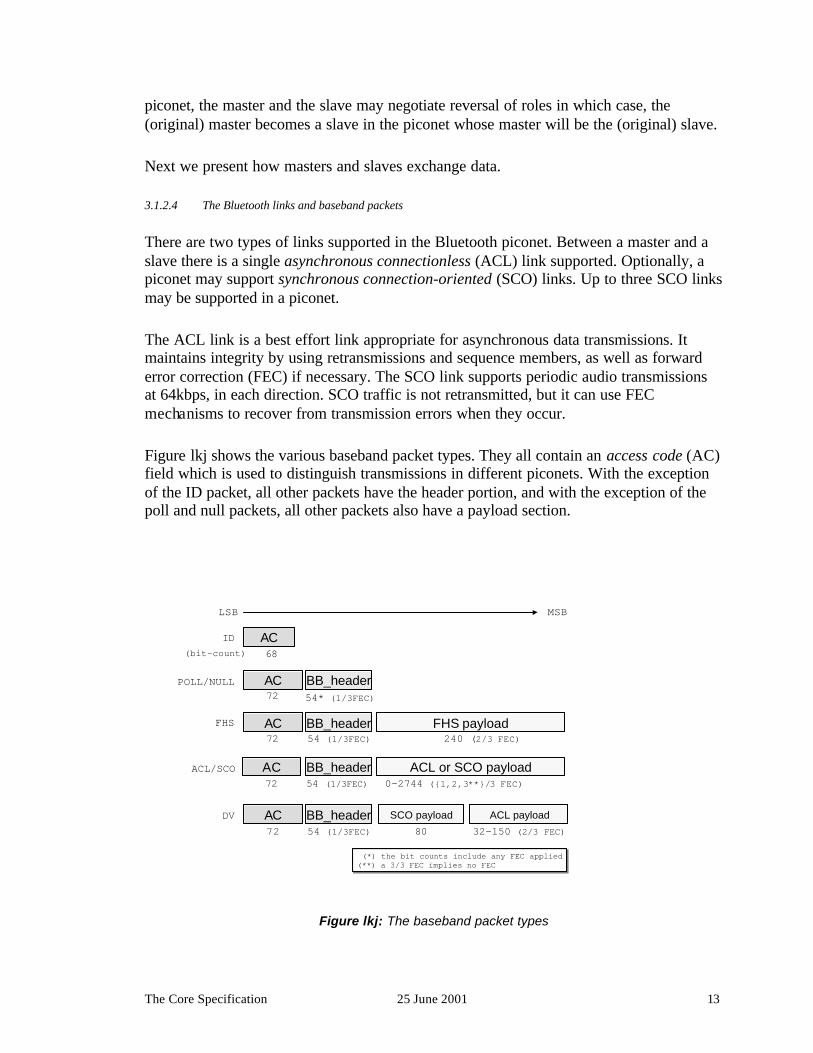
Figure lkj shows the various baseband packet types. They all contain an access code (AC)field which is used to distinguish transmissions in different piconets. With the exceptionof the ID packet, all other packets have the header portion, and with the exception of thepoll and null packets, all other packets also have a payload section.
AC BB_header ACL or SCO payload72 54 (1/3FEC) 0-2744 ({1,2,3**}/3 FEC)
FHS payload
68
240 (2/3 FEC)
(bit-count)AC
BB_header72 54* (1/3FEC)
ID
POLL/NULL
72FHS
ACL/SCO
BB_header SCO payload
72 54 (1/3FEC)ACL payload
80 32-150 (2/3 FEC)DV
LSB MSB
BB_header54 (1/3FEC)
(*) the bit counts include any FEC applied(**) a 3/3 FEC implies no FEC (*) the bit counts include any FEC applied(**) a 3/3 FEC implies no FEC
AC
AC
AC
Figure lkj: The baseband packet types
The Core Specification 25 June 2001 14
The poll packet is used by the master to explicitly poll a slave when no payloadinformation needs to be sent to the slave. The null packet is used to acknowledge atransmission when no payload information needs to be sent.
The frequency hope sequence (FHS) packet is used during the creation of a piconet and itis used to pass address (BD_ADDR and AM_ADDR) and clock information between futuremasters and slaves. The payload of an FHS packet is encoded with a shortened Hammingcode with rate 2/3. The number of bits shown in the figure is after the application of theFEC.
The ACL or SCO packets carry asynchronous and synchronous data in their payloadrespectively. The payload of ACL packets may be encoded with an FEC with rate 2/3, ornot encoded at all. The payload of SCO packets may be encoded with an FEC with rate2/3 or 1/3, or not encoded at all. When the FEC with rate 1/3 is used, each bit is simplyrepeated three times. The data voice (DV) packet is a packet that contains both ACL andSCO data and is transmitted at the periodic instances of regular SCO packet, wheneverthere is a need to send ACL data to the recipient device of the SCO transmission.
AC72
preamble synch word trailer4 68 4
BB_header54 (1/3FEC)
AM_ADDR PDU_type flags (**) HEC
3 4 3 8
SCO payload SCO data({1,2,3*}/3) FEC applied whenever appropriate
ACL payload ACL_pld_hdr ACL_pld_body CRC
({2,3*}/3) FEC applied whenever appropriate
(*) a 3/3 FEC implies no FEC
(**) flags:|flow|ARQ|SEQN|
Figure BB1: The baseband packet fields
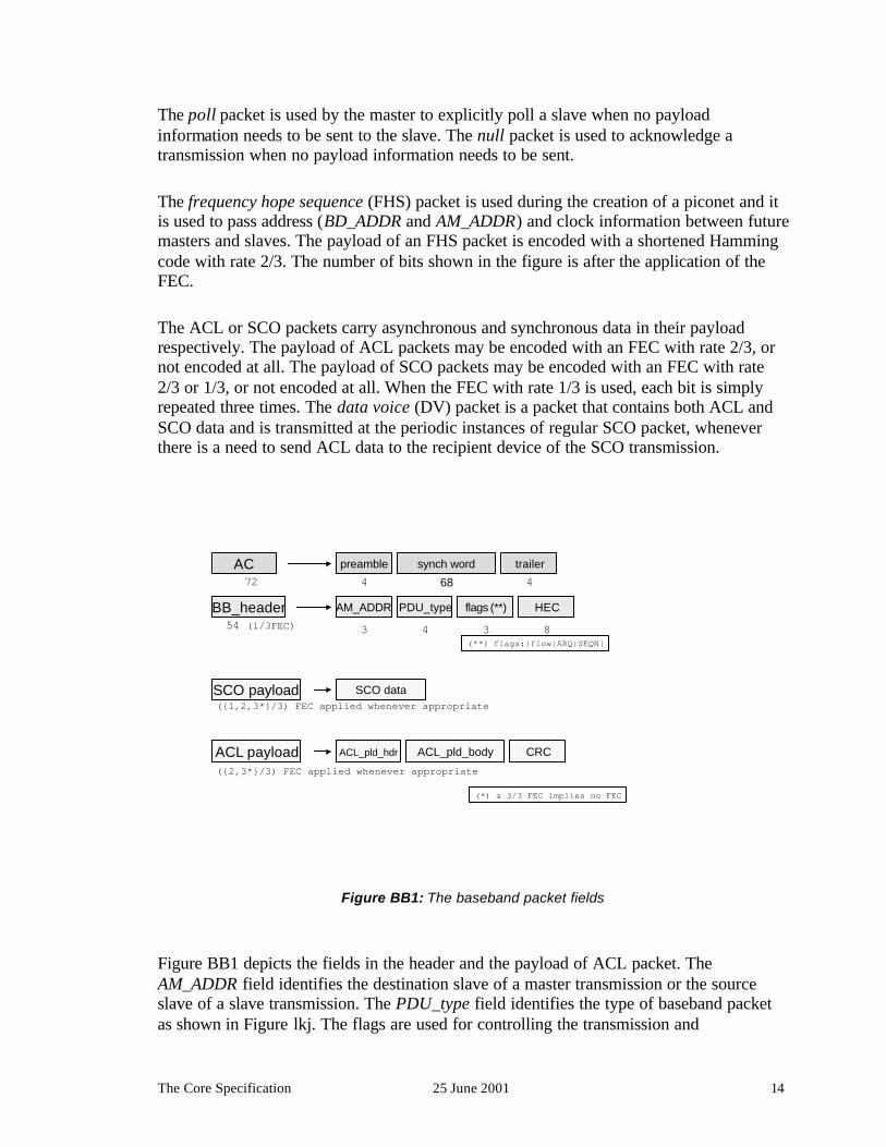
Figure BB1 depicts the fields in the header and the payload of ACL packet. TheAM_ADDR field identifies the destination slave of a master transmission or the sourceslave of a slave transmission. The PDU_type field identifies the type of baseband packetas shown in Figure lkj. The flags are used for controlling the transmission and

The Core Specification 25 June 2001 15
retransmission of ACL packets. In particular, ACL packets use a stop-and-go ARQscheme and a 1-bit sequence number. Furthermore, the ACL link is flow controlled. Theheader is protected by an 8-bit header error check (HEC) code. The ACL payload has itsown header and body portion, see also figure qwe, and it is protected with a 16-bit cyclicredundancy check (CRC).
When AM_ADDR = b‘000’, then the packet is a broadcast packet from the master to allthe slaves. Broadcast packets are not acknowledged and are not retransmitted.
ACL_pld_hdr1 (or 2) octets
ACL_pld_body0 to 339 octets
LSB MSB
(*) for multislot baseband packets(**) present only when length is 9 bits
L_CH flow length reserved2 1 5 or 9(*) 4 (bit-count)
Figure qwe: The ACL packet payload format
The L_CH field in figure qwe is used to identify the logical channel for this basebandtransmission. When L_CH = b‘11’, then the body of the ACL packet payload is passed tothe link manager and is used for the configuration of the Bluetooth link. When L_CH =b‘01’ or b‘01’ then the body is passed to L2CAP for further processing.
Table 2 summarizes the effective payload rates achieved on a Bluetooth link. The notationDM stands for medium rate data, with a 2/3 FEC; the notation DH stands for high ratedata with no FEC. In the symmetric case, two communicating devices, say, Dev_A andDev_B, use the same exactly packet types to communicate. In the asymmetric case, themaximum effective throughput of Dev_A is shown in the forward direction (from Dev_Ato Dev_B), when in the opposing direction (from Dev_B to Dev_A), Dev_B uses one-slotpackets.

The Core Specification 25 June 2001 16
SCO 64 Kbps in each direction
DV packets carry 64 Kbps SCO traffic and and 57.6Kbps of ACL data; ACL data use 2/3-rate FEC
Symmetric (Kbps) Asymmetric (Kbps)
DMx DHxSlot size
x DMx DHxforward reverse forward reverse
1 108.8 172.8 108.8 108.8 172.8 172.8
3 258.1 390.4 387.2 54.4 585.6 86.4
ACL
5 286.7 433.9 477.8 36.3 732.2 57.6
Table 2: Bluetooth link capacities
3.1.3 The Link Manager Protocol (LMP)
The link manager protocol is a transactional protocol between two link managemententities in communicating Bluetooth devices whose responsibility is to set-up theproperties of the Bluetooth link. For LMP packets, the L_CH field in Figure qwe is set tothe binary value b‘11’.
Through LMP transactions, a device may authenticate another one through a challengeresponse mechanism. For authenticated devices, the link may further be encrypted. Twolink managers may learn each other’s features, for example whether the devices supportSCO links, what size of packet transmission do they support, or whether they support anyof the low power consumption modes. SCO connections are established using LMPtransactions, polling intervals and agreed upon packet sizes are also set-up through LMPtransactions.
The Core Specification 25 June 2001 17
ACL_pld_hdr1 octet
ACL_pld_body2 to 17 octets
LSB MSB
L_CH=b’11’ tr_ID opCode LMP_payload
1 7(bit-count) 8-128
LMP packets are encodedwith a 2/3 rate FEC
LMP header
Figure qwt: The LMP packet format
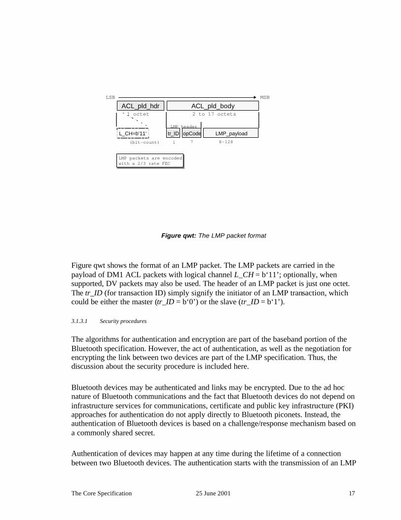
Figure qwt shows the format of an LMP packet. The LMP packets are carried in thepayload of DM1 ACL packets with logical channel L_CH = b‘11’; optionally, whensupported, DV packets may also be used. The header of an LMP packet is just one octet.The tr_ID (for transaction ID) simply signify the initiator of an LMP transaction, whichcould be either the master (tr_ID = b‘0’) or the slave (tr_ID = b‘1’).
3.1.3.1 Security procedures
The algorithms for authentication and encryption are part of the baseband portion of theBluetooth specification. However, the act of authentication, as well as the negotiation forencrypting the link between two devices are part of the LMP specification. Thus, thediscussion about the security procedure is included here.
Bluetooth devices may be authenticated and links may be encrypted. Due to the ad hocnature of Bluetooth communications and the fact that Bluetooth devices do not depend oninfrastructure services for communications, certificate and public key infrastructure (PKI)approaches for authentication do not apply directly to Bluetooth piconets. Instead, theauthentication of Bluetooth devices is based on a challenge/response mechanism based ona commonly shared secret.
Authentication of devices may happen at any time during the lifetime of a connectionbetween two Bluetooth devices. The authentication starts with the transmission of an LMP

The Core Specification 25 June 2001 18
challenge packet. The challenge packet contains a random number generated by thechallenger, which is the device that attempts to authenticate the other device. The receiverdevice of the challenge, called the claimant, operates on the challenge using a 128-bitauthentication key. The claimant returns the result of the operation to the challenger, whocan then compare the result with the expected outcome of the operation and, thus, verifythe identity of the claimant.
To perform an authentication, each device is associated with unit key. In addition, eachpair of devices may have a separate key, call the combination key, used for authenticatingthe specific two devices. Whether the unit key or the combination key is used forauthentication of devices the same procedure is followed. When two devices are unawareof any link keys for performing authentication, e.g., when they connect for the first time, apersonal identification number (PIN) is used to initialize the authentication process. Thesame PIN must be provided in both devices. Devices may have pre-configured PINs, e.g.,a device without a user interface, then for authentication of such devices this PIN must beused.
Dev_A Dev_B
initialauthentication
temporarylink key
temporarylink key
temporary link key generation algorithm
temporary link key generation algorithm
user enters common PIN(initialization)
trust device? trust device?trust is a mutual relation
in future authenticationsuse permanent link key
encrypt link? encrypt link?
no no
generate and storepermanent link key
generate and storepermanent link key
yes yes
encryptiongenerate temporaryencryption link
generate temporaryencryption link
yes yes
encryption is a mutual operation
Figure 123: The security steps
The authentication process is highlighted in figure 123 using two devices, Dev_A andDev_B, which we assume to be foreign to each other. We further assume that the deviceshave authentication enabled.

The Core Specification 25 June 2001 19
Following inquiry, if needed, and paging, Dev_A and Dev_B become members of thesame piconet; for this discussion, it is immaterial which device is the master or the slave.Device, say, Dev_A will initiate authentication of Dev_B. In the absence of a link key forthis authentication, the devices will request the entry of a PIN at the user level. The samePIN needs to be entered in both devices. The PIN will result in temporary link key thatwill be used for an initial authentication of Dev_B.
If the devices are to be trusted for future communications, both devices will generate andstore a permanent link key for communicating with each other. This key will be used forfuture authentication of the devices. Following authentication in one direction,authent ication may occur in the opposite direction as well, where Dev_B authenticatesDev_A.
Following device authentication, the devices may further encrypt the link between them toprotect against eavesdropping. Using the link key, the devices will generate a sequence ofencryption keys to encrypt their transmissions. The encryption key changes with eachpacket transmission.
Encryption is a mutual operation, and encryption encrypts the whole link, both theasynchronous and synchronous transmissions. For broadcast transmission, a master key iscreated by the master that is then passed to slaves using a regular link key. Since,encrypted broadcasts can be decrypted only by the slaves with the master key, the use ofthe encrypted broadcast link can serve as a means to implement multicasting bydistributing the master key only to the members of the multicast group.
The encryption key can be up to 128 bits long. However, the size of the encryption keys isultimately regulated by government authorities. The authentication and encryption keysare generated based on the SAFER+ algorithm; for more information on the algorithm seehttp://csrc.nist.gov/encryption/aes/round1/conf2/papers/massey.pdf.
3.1.3.2 The low power modes
Likewise to the security algorithms, the actual low power mode of operation are part ofthe baseband. However, these modes can be configured and activated via LMPtransactions and they are highlighted here.
In the sniff mode, a slave agrees with its master to listen for master transmissionsperiodically, where the period is configured through LMP transactions.
In the hold mode, a device agrees with its communicating partner in a piconet to remainsilent (in the particular piconet) for a give amount time. A device that has gone into holdmode, does not relinquish its temporary address, AM_ADDR.

The Core Specification 25 June 2001 20
Finally, in the park mode a slave device agrees with its master to park until further notice.As a device enters the park mode, the device relinquishes its active member address,AM_ADDR. While parked, a device will periodically listen to beacon transmissions fromthe master. A device may be invited back to active communications using a broadcasttransmission during a beacon instant. When the slave the wants to be unparked, it wouldsend a message to the master in the slots following the beacon instant.
The above modes of operation are designed for reducing the power consumption of adevice. However, they are optional features. While in any of these modes, a device may beinvolved in other tasks, like entering inquiry scans, participating in active communicationsin another piconet, etc. Hence, the low power modes of operation, while designed for thispurpose, enable additional modes of operation for a device.
3.1.4 The Host Controller Interface (HCI)
As the name states, this is not a protocol per se. It is rather an interface for host devices toaccess the lower layers of the Bluetooth stack through a standardized interface. Throughthe HCI, a host device passes and receives data destined to or coming from anotherBluetooth device. Through the HCI also, a host may instruct its baseband to create a linkto a specific Bluetooth device, execute inquiries, request authentication, pass a link key tothe baseband, request activating a low power mode, etc. The HCI will not be discussedfurther here; for more information, see the Bluetooth specification.
3.1.5 The Logical Link Control & Adaptation Protocol (L2CAP)
The L2CAP layer shields the specifics of the Bluetooth lower layers and provides a packetinterface to higher layers. At the L2CAP layer, the concepts of master and slave devicesdo not exist anymore. The L2CAP supports the multiplexing of several logical channelsover the device’s ACL links; note that a slave has only one ACL link while a master hasone for each slave that it actively communicates with.
L2CAP packets can be much larger than the baseband packets and they may need to besegmented prior to transmission over the air, and reassembled following their receipt. ForL2CAP packets, L_CH field in Figure BB2 is set to the binary value b‘10’ for thetransmission of the first segment of an L2CAP packet, and b‘01’ for subsequent segments.
L2CAP traffic flows over logical channels terminating at the L2CAP layer ofcommunicating devices. Channels may either be connectionless, or connection oriented. Achannel end-point is identified by a two-octet channel identifier (CID); within eachdevice, CIDs of various channels are unique. The connectionless CID has the reservedvalue 0x’0002’. The connection-oriented channels go through a set-up process usingL2CAP signaling. The CID of the signaling channel has the reserved value 0x’0001’.

The Core Specification 25 June 2001 21
L2CAP_hdr4 octets
L2CAP_payload0 to 65,535 octets
length Dst_CID
(octet-count) 2 2
opCode identifier length data ….
PSM CO_payload
1 1 2
2
(a)
(b)
(a) Dst_CID = 0x’0001’(b) Dst_CID = 0x’0002’
Figure rty: The L2CAP packet format
Figure rty summarizes the various types of L2CAP packets. They comprise a header,which is four octets long, and a payload portion, which could be up to 65,535 octets long.Devices with limited capabilities may be able to handle only much smaller packets.Learning the features supported from the other L2CAP entities is part of the L2CAPconnection set-up process.
As figure rty shows, the payload of the L2CAP signalling packets (CID = 0x’0001’)contains signalling information that is formatted with the following fields: (a) a one-octetopCode field to identify the particular signalling data; (b) a one-octet identifier field usedto match responses to requests; (c) a two-byte length field containing the length of the datafield; and (d) the signalling data. An example of a signalling packet is given in figure sdf.
Figure rty also shows the format of a connectionless L2CAP packet. Its payload carriesasynchronous data and the PSM field used for protocol multiplexing as discussed shortly.

The Core Specification 25 June 2001 22
opCode = 0x’02’ identifier length=0x’0004’1 1 2
Source_CID2 2
opCode = 0x’03’ identifier length=0x’0008’
1 1 2
PSM
Source_CID
2 2
Dst_CID
status
2 2
result
connection request
connection response
Figure sdf: The L2CAP connection request and response packets
Figure sdf shows the payload of the connection request and response packets. Inrequesting a channel creation, the requesting L2CAP entity notifies the other side of thelocal CID for the requested channel. Furthermore, it notifies the protocol engine that willprocess the incoming L2CAP payloads. The protocol and services multiplexor (PSM)field is used for supporting protocol multiplexing. The field is typically two octets long,but it can be extended if necessary. The PSM values below 0x’1000’ are reserved. Asfigure rty shows, each connectionless L2CAP packet needs to carry its own PSMinformation. Upon receipt of a connection request, the receiving L2CAP entity willrespond on whether it accepts, or rejects, or needs to process further the connectionrequest. In the latter case, the status field provides information about the need foradditional processing, e.g., authentication pending.
A channel could further be configured for the maximum transmit unit allowed in eachdirection of the transmission. Also, a quality of service negotiation is possible, however,currently only best effort traffic is fully supported over L2CAP channels.
3.2 The middleware protocols
While the transport protocols are involved in every communication of application dataover Bluetooth links, not every middleware protocol participates in Bluetoothcommunications at all times.

The Core Specification 25 June 2001 23
3.2.1 The service discovery protocol (SDP)
I order to support the rich application space envisaged for Bluetooth devices, a servicediscovery protocol (SDP) was added to the basic Bluetooth protocols. Using this protocola Bluetooth device can inquiry of the services that another device across a Bluetooth linkmay have and learn about how to get access to it. The SDP only provides informationabout services, it does not provide access to them. A Bluetooth device may access theservice via different means using the information learned through service discovery.
SDP assumes that a Bluetooth device maintains a logical registry of services it supportsthat are accessible through its Bluetooth interface. SDP is a transactional protocolcomprising of a sequence of requests and responses. The SDP defines how to formulaterequests for information to this registry and how the registry formulates responses to theserequests. The SDP does not define how the registry is implemented, but only how tosubmit valid questions to the registry and how to interpret the answers received from theregistry.
SDP is optimized for usage of devices with possibly limited capabilities over wirelesslinks. Bandwidth is preserved by utilizing binary encoding of information over the air.Universally unique identifiers (UUIDs) are used to describe services and attributes ofthese services in a manner that may not require a central registration authority forregistering services. Typically the UUIDs are 128-bit long, however, for known services16-bit and 32-bit UUIDs may also be used.
SDP packets are carried over connection-oriented L2CAP channels betweencommunicating devices. The PSM value for SDP is reserved and has the value 0x’0001’.There are three types of service request/response transactions. Requests are send by theservice discovery client to a service discovery server and replied the other way around.
Firstly, a client can inquiry a server using a collection of service names, represented as alist of UUIDs. The server returns a list of handles representing the service records in itsservice registry. Secondly, using a known service record handle of a service, the clientmay then retrieve from the server a list of service attributes related to the particularservice, i.e., learn more about the specific service. Thirdly, combining the last two typesof transactions in one step, a client may inquiry a server for a specific class of services andupon return also provide information regarding specific attributes for these services. TheSDP also permits the browsing of services where a client may create a listing of servicesavailable in a server. However, there exists no explicit browsing transaction. It is createdusing the three previously mentioned transaction types.
3.2.2 The RFCOMM protocol
The RFCOMM protocol is an important layer that is used to expose a serial interface tothe packet based Bluetooth transport layers. In particular, the RFCOMM layer emulatesthe signals on the nine wires of an RS-232 interconnect cable. The RFCOMM is based onthe ETSI 07.10 standard permits the emulation and multiplexing of several serial ports

The Core Specification 25 June 2001 24
over a single transport. The multiple ports are identified using the data link connectionidentifier (DLCI).
RFCOMM enables legacy applications that have been written to operate over serial cablesto run on top of a Bluetooth link without modification. Several of the applicationsdeveloped for Bluetooth use the RFCOMM as part of their implementation stack.
3.2.3 The telephony control signalling (TCS) protocol
Telephony control can be performed using the AT command set. Since, the AT commandshave been designed to be passed over serial lines, Bluetooth devices use the RFCOMM tosend and receive control signalling based on the AT command set. For example, usingthese commands, a dialer application in a notebook computer may instruct a cellularphone to dial-up an ISP location.
The AT command set is well-established and it can be used for supporting legacyapplications, like the dialer application. In addition to this control protocol, refer to asTCS-AT, the Bluetooth technical groups developed an additional packet-based telephonycontrol signalling protocol, called TCS-BIN (BIN stands for the binary encoding ofinformation). The TCS-BIN protocol is based on the ITU-T Q.931 standard and it runsdirectly on top of L2CAP. The protocol supports normal telephony control functions likeplacing and terminating a call, sensing ringing tones, accepting incoming calls, etc. UnlikeTCS-AT, TCS-BIN supports point to multi-point communications as well allowing, forexample, a cordless base station to pass the ringing signal of an incoming call to severalcordless headsets associated with the base station.
3.2.4 Other protocols
To support various applications, a number of industry standards have been adopted. Suchprotocols include the point-to-point protocol (PPP), an IETF standard, for enablingcommunications, including IP communications, over serial lines; the object exchange(OBEX) protocol, an IrDA standard, for transporting objects between devices; the infraredmobile communications (IrMC) protocol, an IrDA also standard, for describing andencoding information in business cards, calendar entries, and messages. All theseprotocols are run on top of RFCOMM.
3.3 The Bluetooth profiles
As mentioned earlier, the Bluetooth specification comprises not only communicationsprotocols but applications as well. This sets the Bluetooth wireless technology apart frommany other communications technologies that focus primarily on the physical, data linkand possibly networking aspects of communications. Since, the Bluetooth wirelesstechnology is to be used primarily by consumers, the technology must require minimaltechnical expertise from its users. For this to be possible, a set of simple but usefulapplications had to be developed to allow Bluetooth devices to perform useful tasks withother Bluetooth devices right out of the box. This would provide value-add to the users of

The Core Specification 25 June 2001 25
the technology and aid in establishing this technology as the de facto means for short-range communications of personal devices.
The specifications for building interoperable applications are called profiles. Actually,there are two types of profiles, protocol profiles and application profiles. The profilesdefined in version 1.1 of the specification are summarized in figure yui. Profiles can bebased on other profiles as well, thus figure yui also shows the relation between theprofiles.
service discovery appl. pr.
Telephony(TCS-BIN)
intercomprofile
cordlesstelephony
profile
serialport
profile
genericobject
exchange pr.
filetransferprofile
object pushprofile
synchprofile
faxprofile
dial-upnetworking
profile
LANaccessprofile
headsetprofile
Generic access profileGeneric access profile
Figure yui: The Bluetooth profiles
All profiles depend on the Generic Access Profile (GAP) which defines the basic rulesand conditions for connecting devices with each other and establishing Bluetooth linksand L2CAP channels. It also defines security levels according to which devices may allowthemselves to be discovered, or allowed to be connected, be authenticated or authenticateother devices, etc. It defines the conditions necessary to establish trust relations betweendevices, see figure 123.
There are two protocol profiles, which depend on each other. The serial port profiledefines how RFCOMM runs on top of the Bluetooth transport protocols, while the genericobject exchange profile defines how object can be exchanged using the OBEX protocolrunning on top RFCOMM as defined in the serial port profile. Depending on the previousprofile, there are profiles describing how to synchronize personal informationmanagement (PIM) data, how to push (and pull) objects, e.g., business cards, and how totransfer files. Based on the serial port profile there are also additional profiles related to

The Bluetooth Qualification Program 25 June 2001 26
the use of cellular phones as modems for dial-up networking, connecting to a wirelessheadset, sending faxes, or accessing LAN services through a LAN access point.
There are two profiles based on the TCS-BIN protocol which describe two aspects of theso called 3-in-1 usage scenario, where a cellular phone can be used as a headset in acordless telephony system or as an intercom device to communicate directly with othercellular phones.
Finally, there is the service discovery application profile that shows how a servicediscovery application uses the service discovery protocol and, furthermore, how the latterprotocol uses the Bluetooth transports for carrying the service discovery packets betweena service discovery client and a server.
4 THE BLUETOOTH QUALIFICATION PROGRAM
The Bluetooth qualification program (BQP) is an integral part of the Bluetooth wirelesstechnology. It is a program designed to test compliance to the specification and productinteroperability. The latter implies that not only compliance to the protocol specification istested but also test whether applications claimed to follow a Bluetooth profile behave asexpected. The BQP does not deal with the regulatory type approvals that are administeredby national and international authorities. Manufacturers will need type approvals for theirproducts before they can sell them in the market. For example, in the USA, a Bluetoothdevice needs to be certified as compliant to the FCC part 15 regulations.
Only products qualified through the BQP can be called Bluetooth products, receive theBluetooth free license, and bear the Bluetooth trademarks. The BQP is the mechanism bywhich the Bluetooth brand is protected assuring users of the technology a certain level ofconfidence in the product and also in the functionality of products carrying the Bluetoothtrademarks. Only products from adopter members can be qualified. Qualified products arepublished in the official Bluetooth website.
Testing in the BQP includes the following:
? radio qualification testing;
? protocol conformance testing –this includes the Bluetooth transport protocols and theservice discovery protocol);
? profile conformance testing –at a minimum, this includes conformance to the genericaccess profile;
? profile interoperability testing – for additional profiles.

Additional Activities 25 June 2001 27
Not all products need to go through all the tests mentioned above. Tested products mayinclude anything from basic Bluetooth radio components, to complete products, e.g., awireless headset, or a cellular phone with an integrated Bluetooth subsystem. The breadthof testing depends on the particular product considered.
The program includes implementation conformance statements (ICSs), wheremanufacturers declare the features that their products support; possibly, product testing bythe manufacturer; and testing in a Bluetooth Qualification Testing Facility (BQTF).Manufacturers submit their ICSs and test results to a Bluetooth Qualification Body(BQB), who is a person authorized to review the test reports and manufacturerdeclarations and approve products. When the BQB approves a product, the new Bluetoothproduct is added in the listing of qualified Bluetooth products, which is available throughthe Bluetooth web-site.
5 ADDITIONAL ACTIVITIES
5.1 The SIG
The work in the Bluetooth SIG did not end with the release of the Bluetooth 1.0Aspecification. The SIG has been heavily involved in promoting the technology andorganizing Bluetooth Developers conferences, which are technical forums, where productdevelopers, and potential customers may learn of the latest developments about thetechnology and have the opportunity to meet with each other. The SIG also encourages“unplug” fests, where manufacturers can test their products against each other andexchange technical information in order to achieve high degree of productinteroperability. The unplug fests are not part of the BQP, but they provide a diverseforum for product interoperability testing. The regulatory group of the SIG collaborateswith other similar bodies in the industry and is actively engaging authorities in variouscountries in an effort to harmonize the spectrum allocation in the 2.4 GHz in thesecountries.
The technical groups within the SIG are maintaining the specification by administering anerrata process and developing a new set of protocols and profiles. New technical workfocuses on
? enhanced radio capabilities with backward compatible faster radios;
? study any co-existence issues between technologies sharing the 2.4 GHz ISM band,like the Bluetooth wireless technology, IEEE 802.11 wireless LANs, HomeRF,cordless telephony, etc.;
? support for IP networking without the use of the RFCOMM and PPP;
? support for higher level service discovery methods, like UpnP;

Additional Activities 25 June 2001 28
? develop communication solutions for usage scenarios involving:
? in vehicle communications, printing, transfer of digital images, richer audio, voice,and video experience, distribution of location information, using the unrestricteddigital information (UDI) extensions for 3G handsets in Japan.
5.2 IEEE 802.15
Another forum where personal area networks are being standardized is the IEEE 802LAN/MAN standards committee. In March 1999, the IEEE 802.15 working group wascreated to develop a family of communications standards for wireless personal areanetworks™ (WPANs™).6 In the first meeting of the new working group in July 1999, theBluetooth SIG submitted the just created Bluetooth specification as a candidate for anIEEE 802.15 standard. The Bluetooth proposal was chosen to serve as the baseline of thefirst 802.15 draft standard.
As mentioned earlier, the Bluetooth specification describes a complete solution includingcommunication protocols and applications. The IEEE 802 standard are dealing only withthe lower two layers of the OSI stack: the physical layer (PHY) and the medium accesscontrol sub-layer (MAC) of the data link control layer. As such, there is no immediatemapping between the Bluetooth specification and an IEEE 802 standard. The 802.15.1task group decided to base its MAC and PHY on the Bluetooth transport protocols. Thiswas done because all of the latter protocols are involved in data communications betweenBluetooth devices. Any smaller subset of protocols would have created a daunting task todissect the Bluetooth specification in an unnatural, hardly verifiable manner. Any largerset of protocols would have included either protocols not always present in Bluetoothcommunications, like RFCOMM, or protocols not related with the normal transport ofdata between Bluetooth devices, like SDP.
6 Wireless Personal Area Network and WPAN (and their plural versions) are trademarks of IEEE.

Summary 25 June 2001 29
Radio
Baseband
Link Manager
L2CAP
TCSRFCOMM SDP
Applications/Profiles
HCI
Other
C_PA_P
Physical
Data Link Control
Network
Transport
Session
Presentation
Application
Logical LinkControl
Logical LinkControl
MACMAC
PHYPHY
OSI layersOSI layers 802 standards802 standards
802.15.1Bluetooth
WPAN
802.15.1Bluetooth
WPAN
Figure 789: Relation between the OSI layer, the IEEE 802 layers and the Bluetooth stack
Figure 789 depicts the relation between the OSI model layers, the focus of the IEEE 802standards and how the 802.15.1 effort relates to the Bluetooth stack. As of this writing, thedevelopment of the draft standard is at final stages, short of going for sponsor balloting.
Since the formation of 802.15.1 task group, additional task groups have been formed tostudy additional aspects of WPANs. The 802.15.2 task group studies coexistence issuesbetween 802 wireless technologies. The 802.15.3 task group is developing standards forhigh rate radios (>20Mbps). Finally, the 802.15.4 task group is developing standards forlow rate radios (<200Kbps).
6 SUMMARY
The Bluetooth wireless technology is a specification for short-range, low-cost, and smallform-factor that enables user-friendly connectivity among portable and handheld personaldevices, and provides connectivity of these devices to the internet. The technologysupports both asynchronous data flows and synchronous audio streams over links withraw link speed of 1Mbps. It operates in the 2.4 GHz ISM band utilizing low transmitpower radios, typically 0dBm, using a frequency hoping spread spectrum technique. TheBluetooth specification is an on going process steered by the promoters of the BluetoothSIG and developed by contributing SIG members.
The SIG recognized that the technology would be successful if it is widely available anduseful tasks can be done with it from the early days of it use. For this reason, theBluetooth specification comprises a protocol stack provided by a hardware and software

Summary 25 June 2001 30
description and an application framework, called profiles, for building interoperableapplications. Furthermore, the technology is provided license-free to the adoptersmembers of the technology. The Bluetooth qualification program, which is applicableonly on potential Bluetooth products by adopter members, has been designed to build,promote, and maintain a level of confidence to the users of the technology that they areusing a product that was built in manner compliant to the Bluetooth specification.Furthermore, it can interact with other devices and behave as expected when executingany application claimed to be conformant to the Bluetooth profiles.
The Bluetooth movement started in May 1998 and it has been followed very closely bythe technical community, the business community, all sorts of market analysts and gurusand the media. As of this writing, almost two years after the release of the Bluetoothspecification, it appears that the deployment of the technology is moving slower thanexpected. That is actually quite understandable and it is common with any newtechnology; for example, the development of the 802.11 technology starter in the early1990s, and it took a good portion of a decade before it started spreading.
The slower than anticipated pace of deployment of the Bluetooth wireless technology isunderstandably notable. However, the expectations for the potentials for the technologydoes seem to have diminished, only shifted in time. The image of a single technology thatenables a personal area network that moves as humans move and brings worry-free, adhoc connectivity to personal devices at home and in the workplace, in the car and in themall, in the airport and in the ballpark, etc., is too strong a paradigm to ignore it. Today, aswas in the May of 1998, the only technology that still has the possibility to succeed in thisspace is the Bluetooth wireless technology.
IN MEMORY OF…
Dr. Richard LaMaire, a dear friend and esteemed colleague, that passed away as thefinishing touches of this article were being made.
ADDITIONAL RESOURCES
The Bluetooth specification is available free of charge on the official Bluetooth web-siteat http://www.bluetooth.com. The site contains plenty of information regarding thetechnology and how the SIG operates. The site has also a listing of the Bluetooth qualifiedproducts. A very good technical article written by one of the innovators of the Bluetoothwireless technology, Dr. Jaap C. Haartsen, titled The Bluetooth Radio System, can befound in the special issue on “Connectivity and Applications Enablers for UbiquitousComputing and Communications” of IEEE Personal Communications, February 2000.The same issue contains a paper by Tom Siep, et al, on the process of developing the802.15 standard, titled Paving the Way for Personal Area Network Standards: AnOverview of the IEEE P802.15 Working Group for Wireless Personal Area Networks; theactivities of the IEEE 802.15 working group can be found athttp://grouper.ieee.org/groups/802/15/. Bluetooth Revealed (Prentice-Hall PTR, 2001),

Summary 25 June 2001 31
authored by Brent A. Miller and myself, highlights the 1,600 pages of the specificationspiced with trivia from the development of the specification as experienced by authors. Agood article highlighting the technology with emphasis the qualification program isBluetooth’s slow dawn, by Ron Schneiderman, in IEEE Spectrum, November 2000.Bluetooth: Connect Without Cables, Jennifer Bray and Charles F. Sturman provides a lotof useful information about the Bluetooth specification for implementers and productdevelopers.


![IBM Research Reportdomino.watson.ibm.com/library/CyberDig.nsf/papers/7926F...Recently, Balas and Saxena [6] and Dash, Gunl¨ uk and Lodi [23] approximately optimized over the¨ split](https://static.fdocuments.in/doc/165x107/5ae0ff087f8b9a595d8b4dd5/ibm-research-balas-and-saxena-6-and-dash-gunl-uk-and-lodi-23-approximately.jpg)

