i IRISH AVIATION AUTHORITY AERODROME LICENSING MANUAL
240
Irish Aviation Authority January 2014 Aerodrome Licensing Manual Foreword and Definitions i Aerodrome Licensing Memorandum (ALM) ALM. No: 002 January 2014 Title AERODROME LICENSING MEMORANDUM (A.L.M) 002 IRISH AVIATION AUTHORITY AERODROME LICENSING MANUAL AERODROME LICENSING MEMORANDUM (A.L.M) 002 Designated Authority: Aerodrome Standards Department Irish Aviation Authority The Times Building 11-12 D’Olier Street Dublin 2 Telephone: 01 6031500 Fax: 01 6774460
Transcript of i IRISH AVIATION AUTHORITY AERODROME LICENSING MANUAL
Irish Aviation Authority January 2014
Aerodrome Licensing Manual Foreword and Definitions i
Aerodrome Licensing Memorandum (ALM)
ALM.
No: 002
January 2014
Title AERODROME LICENSING MEMORANDUM (A.L.M) 002
IRISH AVIATION AUTHORITY
AERODROME LICENSING MANUAL
AERODROME LICENSING MEMORANDUM (A.L.M) 002
Designated Authority: Aerodrome Standards Department Irish Aviation Authority The Times Building 11-12 D’Olier Street Dublin 2 Telephone: 01 6031500 Fax: 01 6774460

Irish Aviation Authority January 2014
ii Foreword and Definitions Aerodrome Licensing Manual
Record of Amendments
Third Issue - January 2014
Amendment No.
Issue Date: Date Entered:
Entered By: Comments:
1 June 2010 Included IAA
2 Jan 2014 Included IAA Annex 14 Sixth Edition
January 2014 Irish Aviation Authority
Aerodrome Licensing Manual Foreword and Definitions iii
CONTENTS Page
FOREWORD ......................................................................................................................... iv DEFINITIONS ....................................................................................................................... vi
CHAPTER 1 AERODROME DATA .........................................................................................1 1.1 Introduction ……………………………………………………………………… ................. 1 1.2 Specifications for the Determination of Aerodrome Data……………………………….. 2 1.3 Aerodrome Data to be Determined and Reported ...……………………… . ……………2
CHAPTER 2 AERODROME PHYSICAL CHARACTERISTICS ............................................ 9 2.1 2.2
Introduction…………………………………………………………………………………... 9 Aerodrome Reference Point…………………………………………………………… ..... 9
2.3 Aerodrome Reference Code………………..........… ......................................... ………9 2.4 Runways ................................................................................................................... 10 2.5 Taxiways .. ……………………………………………………………………………………26 2.6 Aprons……………………………………………………………………………………......32 defined. 2.7 Isolated Aircraft Parking Position…………………………………………………… . ……33 2.8 De-Icing/Anti-Icing Facilities…………………………………………………………….....34 not defined. APPENDIX 2A Movement Area BearingStrength……………………………………………...37 not defined. APPENDIX 2B Declared Distances………………………………………………………….. .... 40
CHAPTER 3 AERODROME GROUND LIGHTING .............................................................. 43 3.1 Introduction………………………………………………………………………………… .. 43 3.2 General Requirements…….………………………………………………………………. 43 3.3 Aeronautical Beacons………………………………………………………………… ....... 52 3.4 Approach Lighting System…………………………………………………………........... 54 3.5 Visual Approach Slope Indicator Systems………………………..……………………. .. 59 3.6 Runway Lighting Systems………………………..……………………. .......................... 64 3.7 Taxiway, Apron and Aircraft Stand Lights………………………………………………. . 70 3.8 Flight Checking of Visual Aids……………………………………………………………. . 83 APPENDIX 3A Typical Lighting Configurations….………………………………………… ..... 85 APPENDIX 3B PAPI and APAPI Characteristics……………………………..… ................... 95
CHAPTER 4 AERODROME SIGNALS, MARKINGS, SIGNS AND MARKERS .................. 99 4.1 Introduction………………………………………………………………………………… . .99 4.2 Signals…….……………………………………………………………………………….. .. 99 4.3 Markings for Denoting Restricted Use Area……………………………………………. 101 4.4 Pavement Markings………………………………………………………………………. 103 4.5 Runway Markings…………..……………………………………………………………. . 104 4.6 Taxiway and Other Markings…………………………………………………………… . 109 4.7 Signs………………………………………………………………………………………. . 115 4.8 Markers…………………………………………………………………………………… .. 123 APPENDIX 4A Figures Illustrating Markings and Signs……………………… ................... 127 APPENDIX 4B Mandatory Instruction and Information Markings…………………………. . 137 APPENDIX 4C Requirements Concerning Design of Taxiing Guidance Signs ………… . 143
Irish Aviation Authority January 2014
iv Foreword and Definitions Aerodrome Licensing Manual
CHAPTER 5 THE ASSESSMENT AND TREATMENT OF OBSTACLES .......................... 153 5.1 Introduction……………………………………………………………………………… ... 153 5.2 Obstacle Limitation Surfaces…….…………………………………………………….. .. 153 5.3 Obstacle Limitation Requirements…………………………………………… .............. 161 5.4 Visual aids for denoting obstacles……………………………………………………. ... 172 CHAPTER 6 EMERGENCY SERVICES ............................................................................ 185 6.1 Aerodrome Emergency Planning……………………………………………………… .. 185 6.2 Rescue and Fire Fighting…….…………………………………………………….. ....... 187 APPENDIX 6A Rescue and Fire Fighting: Supplementary Information ............................ 195 APPENDIX 6B Aeroplane Classification……. .................................................................. 197 APPENDIX 6C Provision of Additional Water …………………………. ............................. 199 APPENDIX 6D Rescue Equipment to be Carried on RFF Vehicles………………………. . 201 APPENDIX 6E Rescue and Fire Fighting Service: Personnel ………… ........................... 203
CHAPTER 7 GENERAL SERVICES .................................................................................. 207 7.1 Disabled Aircraft Removal……………………………………………………… ............ 207 7.2 Maintenance: General…….…………………………………………………….. ............ 207 7.3 Pavements……………………………………………………… .................................... 207 7.4 Runway Pavement Overlays …….…………………………………………………….. . 209 7.5 Wildlife Strike Hazard Reduction……………………………………………………… ... 210 7.6 Apron Management…….…………………………………………………….. ................ 210 7.7 Ground Servicing of Aircraft……………………………………………………… .......... 211 7.8 Security…….…………………………………………………….. .................................. 211 7.9 Siting of Equipment and Installations on Operational Areas…… ............................. 212 7.10 Aerodrome Vehicle Operations….…………………………………………………….. .. 213 7.11 Surface Movement Guidance and Control Systems………………………………… .. 215
CHAPTER 8 SAFETY MANAGEMENT ............................................................................. 217 8.1 General……………………………………………………… ......................................... 217 APPENDIX 8A Framework for Safety Management Systems (SMS)………………….. .... 218
January 2014 Irish Aviation Authority
Aerodrome Licensing Manual Foreword and Definitions v
FOREWORD 1 The Irish Aviation Authority Act 1993 (amended 1998) empowers the IAA: 2
(a) to grant an applicant a licence in respect of an aerodrome in the State subject to such conditions as the Authority thinks fit, and
(b) to require that any or all of the provisions of the International Standards and
Recommended Practices as set out in Annex 14 to the Convention on International Civil Aviation shall be applicable to an aerodrome in the State.
3 The purpose of this manual is to give guidance to applicants and licensees on the
procedure for the issue, continuation of or variation to an aerodrome licence and to indicate the licensing requirements that are used for assessing such application. These requirements reflect the Standards and Recommended Practices of Annex 14 (Latest Edition) and form a basis for a judgement on the potential suitability of the aerodrome to be licensed taking account of the scale and scope of the flying activity which is to take place there.
4 All aerodromes differ and to deal with the different situations the requirements
specified in ICAO Annex 14 are classified as “Standards” or “Recommended Practices”. In Annex 14 Standards are phrased using the word “shall” and Recommended Practises are phrased using the word “should”. To identify the relative status of the requirements the same phraseology is repeated in this document and the word “shall” when used in this context, is printed in bold italic. This does not mean that compliance with a requirement when the word “should” is used is optional but rather that, where insurmountable difficulties exist the Authority may accept an alternative means of compliance provided that an acceptable safety assurance is received from the applicant or licensee.
5 Any limiting conditions or mitigating measures described in the safety assurance that
compensate for any increased risk will take account of the anticipated flying activity and any other non-compliances from the licensing requirements that may already exist. Thereafter the licensee and the Authority will review periodically the implications of non-compliance with the licensing requirements and associated conditions or mitigating measures, in particular when any significant change in activity or aerodrome development is proposed.
6 Significant changes in the nature and the scale of flying activity at a licensed
aerodrome shall be notified to the Authority as soon as practicable. Where development work, including changes to the physical characteristics, rescue and fire-fighting services, aerodrome lighting and other visual aids is proposed, the Authority shall be consulted beforehand in accordance with the conditions of the licence.
7 In Ireland, an aerodrome licensed by the Authority for aeroplane operations is
considered to be certificated in accordance with the requirements of Annex 14, Volume 1, Section 1.4.
Irish Aviation Authority January 2014
vi Foreword and Definitions Aerodrome Licensing Manual
DEFINITIONS
When the following terms are used in the ALM they have the following meanings: Accuracy:
A degree of conformance between the estimated or measured value and the true value.
Note: For measured positional data, the accuracy is normally expressed in terms of a distance from a stated position within which there is a defined confidence of the true position falling.
Aerodrome:
A defined area on land or water (including any buildings, installations and equipment) intended to be used either wholly or in part for the arrival, departure and surface movement of aircraft.
Aerodrome authority: The licensee or the person or persons
having charge of a Licensed Aerodrome. Aerodrome beacon: Aeronautical beacon used to indicate the
location of an aerodrome from the air. Aerodrome certificate:
A certificate or issued by the appropriate authority under applicable regulations for the operation of an aerodrome.
Aerodrome elevation: The elevation of the highest point of the
landing area. Aerodrome identification sign:
A sign placed on an aerodrome to aid in identifying the aerodrome from the air.
Aerodrome licence:
A certificate issued by the Aerodrome Standards Department of the Irish Aviation Authority under applicable regulations for the operation of an aerodrome.
Aerodrome reference point:
The designated geographical location of an aerodrome.
Aerodrome mapping data (AMD)
Data collected for the purpose of compiling aerodrome mapping information for aeronautical uses. Note — Aerodrome mapping data are collected for purposes that include the improvement of the user’s situational awareness, surface navigation operations, training, charting and planning.
January 2014 Irish Aviation Authority
Aerodrome Licensing Manual Foreword and Definitions vii
Aerodrome mapping database (AMDB)
A collection of aerodrome mapping data organized and arranged as a structured data set.
Aerodrome traffic density:
(a) Light: Where the number of movements in the mean busy hour is not greater than 15 per runway or typically less than 20 total aerodrome movements.
(b) Medium: Where the number of movements in the mean busy hour is of the order of 16 to 25 per runway or typically between 20 to 35 total aerodrome movements.
(c) Heavy: Where the number of movements in the mean busy hour is of the order of 26 or more per runway or typically more than 35 total aerodrome movements.
Notes: 1. The number of movements in the
mean busy hour is the arithmetic mean over the year of the number of movements in the daily busiest hour.
2. Either a take-off or a landing
constitutes a movement. Aeronautical beacon:
An aeronautical ground light visible at all azimuths, either continuously or intermittently, to designate a particular point on the surface of the earth.
Aeronautical ground light:
Any light specially provided as an aid to air navigation, other than a light displayed on an aircraft.
Aeroplane reference field length:
The minimum field length required for take-off certificated take-off mass, sea level, standard atmospheric conditions, still air and zero runway slope, as shown in the appropriate aeroplane flight manual prescribed by the certificating authority or equivalent data from the aeroplane manufacturer. Field length means balanced field length for aeroplanes, if applicable, or take-off distance in other cases.
Irish Aviation Authority January 2014
viii Foreword and Definitions Aerodrome Licensing Manual
Air Traffic Control: The service provided to regulate the activities of aircraft and vehicles on the manoeuvring area.
Aircraft Classification Number (ACN):
A number expressing the relative effect of an aircraft on a pavement for a specified standard subgrade category.
Aircraft stand: A designated area on an apron intended to be used for parking an aircraft.
Apron: A defined area on a land aerodrome intended to accommodate aircraft for purposes of loading or unloading passengers, mail or cargo, fuelling, parking or maintenance.
Apron management service: A service provided to regulate the activities and the movement of aircraft and vehicles on the apron.
Authority: The Aerodrome Standards Department of the Irish Aviation Authority.
Balked Landing: A landing manoeuvre that is unexpectedly discontinued at any point below the obstacle clearance altitude/height (OCA/H).
Barrette: Three or more aeronautical ground lights closely spaced in a transverse line so that from a distance they appear as a short bar of light.
Calendar: Discrete temporal reference system that provides the basis for defining temporal position to a resolution of one day (ISO 19108*).
Capacitor discharge light: A lamp in which high intensity flashes of extremely short duration are produced by the discharge of electricity at high voltage through a gas enclosed in a tube.
Certified Aerodrome: An aerodrome whose operator has been granted an aerodrome certificate or licence.

January 2014 Irish Aviation Authority
Aerodrome Licensing Manual Foreword and Definitions ix
Clearway:
A defined rectangular area on the ground or water under the control of the appropriate authority, selected or prepared as a suitable area over which an aeroplane may make a portion of its initial climb to a specified height.
Cyclic redundancy check (CRC):
A mathematical algorithm applied to the digital expression of data that provides a level of assurance against loss or alteration of data.
Data quality:
A degree or level of confidence that the data provided meet the requirements of the data user in terms of accuracy, resolution and integrity.
Datum:
Any quantity or set of quantities that may serve as a reference or basis for the calculation of other quantities (ISO 19104*)
De-icing/anti-icing facility:
A facility where frost, ice or snow is removed (de-icing) from the aeroplane to provide clean surfaces and/or where clean surfaces of the aeroplane receive protection (anti-icing) against the formation of frost or ice and accumulation of snow or slush for a limited period of time.
Note: Further guidance is given in the ICAO Manual of Aircraft Ground De/anti-icing operations (Doc 9640).
De-icing/anti-icing pad:
An area comprising an inner area for the parking of an aeroplane to receive de-icing/anti-icing treatment and an outer area for the manoeuvring of two or more mobile de-icing/anti-icing equipment.

Irish Aviation Authority January 2014
x Foreword and Definitions Aerodrome Licensing Manual
Declared distances:
a) Take-off run available (TORA). The length of runway declared available and suitable for the ground run of an aeroplane taking off b) Take-off distance available (TODA). The length of the take-off run available plus the length of the clearway if provided c) Accelerate-stop distance available (ASDA). The length of the take off run available plus the length of the stopway, if provided d) Landing distance available (LDA). The length of runway which is declared available and suitable for the ground run of an aeroplane landing.
Dependent parallel approaches
Simultaneous approaches to parallel or near-parallel instrument runways where radar separation minima between aircraft on adjacent extended runway centre lines are prescribed.
Displaced threshold:
A threshold not located at the extremity of a runway.
Effective intensity:
The effective intensity of a flashing light is equal to the intensity of a fixed light of the same colour which will produce the same visual range under identical conditions of observation.
Ellipsoid height (Geodetic height):
The height related to the reference ellipsoid, measured along the ellipsoidal outer normal through the point in question.
Fixed light:
A light having constant luminous intensity when observed from a fixed point.
Frangible object:
An object of low mass designed to break, distort or yield on impact so as to present the minimum hazard to aircraft.
Geodetic datum:
A minimum set of parameters required to define location and orientation of the local reference system with respect to the global reference system/frame.
Irish Aviation Authority January 2014
Aerodrome Licensing Manual Foreword and Definitions xi
Geoid:
The equipotent surface in the gravity field of the Earth which coincides with the undisturbed mean sea level (MSL) extended continuously through the continents.
Note: The geoid is irregular in shape because of local gravitational disturbances (wind tides, salinity, current, etc) and the direction of gravity is perpendicular to the geoid at every point.
Geoid undulation:
The distance of the geoid above (positive) or below (negative) the mathematical reference ellipsoid.
Note: In respect to the World Geodetic System – 1984 (WGS-84) defined ellipsoid, the difference between the WGS-84 ellipsoid height and orthometric height represents WGS-84 geoid undulation.
Gregorian calendar:
Calendar in general use; first introduced in 1582 to define a year that more closely approximates the tropical year than the Julian Calendar (ISO 19108*).
Note: In the Gregorian calendar, common years have 365 days and leap years 366 days divided into twelve sequential months.
Hazard beacon: An aeronautical beacon used to designate
a danger to air navigation.
Heliport:
An aerodrome or a defined area on a structure intended to be used wholly or in part for the arrival, departure and surface movement of helicopters.
Holding bay:
A defined area where aircraft can be held or by-passed to facilitate efficient surface movement of aircraft.
Holdover time:
The estimated time the anti-icing fluid (treatment) will prevent the formation of ice and frost and the accumulation of snow on the protected (treated) surfaces of an aeroplane.
Irish Aviation Authority January 2014
xii Foreword and Definitions Aerodrome Licensing Manual
Hot spot
A location on an aerodrome movement area with a history or potential risk of collision or runway incursion, and where heightened attention by pilots/drivers is necessary.
Human Factors principles:
Principles which apply to aeronautical design, certification, training, operations and maintenance and which seek safe interface between the human and other system components by proper consideration to human performance.
Human performance:
Human capabilities and limitations which have an impact on the safety and efficiency of aeronautical operations.
Identification beacon:
An aeronautical beacon emitting a coded signal by means of which a particular point of reference may be identified.
Independent parallel approaches:
Simultaneous approaches to parallel or near-parallel instrument runways where radar separation minima between aircraft on adjacent extended runway centre lines are not prescribed.
Independent parallel departures:
Simultaneous departures from parallel or near-parallel instrument runways.
January 2014 Irish Aviation Authority
Aerodrome Licensing Manual Foreword and Definitions xiii
Instrument runway:
One of the following types of runways intended for the operation of aircraft using instrument approach procedures: (a) Non-precision approach runway: An instrument runway served by visual aids and a non visual aid providing at least directional guidance adequate for a straight-in approach. (b) Precision approach runway, category 1: An instrument runway served by ILS and/or MLS and visual aids intended for operations with a decision height not lower than 200 ft. and either a visibility not less than 800 m or an RVR not less than 550 m. (c) Precision approach runway, category 11: An instrument runway served by ILS and/or MLS and visual aids intended for operations with a decision height lower than 200 ft but not lower than 100 ft and a runway visual range not less than 300 m. (d) Precision approach runway category 111: An instrument runway served by ILS and/or MLS to and along the surface of the runway and: A - intended for operations with a decision height lower than 100 ft or no decision height and an RVR not less than 175 m.
B - intended for operations with a decision height lower than 50 ft or no decision height and an RVR less than 175 m but not less than 50 m.
C - intended for operations with no decision height and no RVR limitations.
Notes: 1. See Annex 10, Volume 1 for related ILS
and/or MLS specifications.
2. Visual aids need not necessarily be matched to the scale of non-visual aids provided. The criterion for the selection of visual aids is the conditions in which the operations are intended to be conducted.
Irish Aviation Authority January 2014
Aerodrome Licensing Manual Foreword and Definitions xiv
Integrity (aeronautical data):
A degree of assurance that an aeronautical data and its value has not been lost nor altered since the data origination or authorized amendment.
Integrity classification (aeronautical data).
Classification based upon the potential risk resulting from the use of corrupted data. Aeronautical data is classified as: a) routine data: there is a very low probability when using corrupted routine data that the continued safe flight and landing of an aircraft would be severely at risk with the potential for catastrophe; b) essential data: there is a low probability when using corrupted essential data that the continued safe flight and landing of an aircraft would be severely at risk with the potential for catastrophe; and c) critical data: there is a high probability when using corrupted critical data that the continued safe flight and landing of an aircraft would be severely at risk with the potential for catastrophe.
Intermediate holding position:
A designated position intended for traffic control at which taxiing aircraft and vehicles shall stop and hold until further cleared to proceed, when so instructed by the aerodrome control tower.
Landing area:
That part of a movement area intended for the landing or take-off of aircraft.
Landing direction indicator:
A device to indicate visually the direction currently designated for landing and taking-off.
Laser-beam critical flight zone (LCFZ):
Airspace in the proximity of an aerodrome but beyond the LFFZ where the irradiance is restricted to a level unlikely to cause glare effects.
Laser-beam free flight zone (LFFZ):
Airspace in the immediate proximity to the aerodrome where the irradiance is restricted to a level unlikely to cause any visual disruption.
Irish Aviation Authority January 2014
Aerodrome Licensing Manual Foreword and Definitions xv
Laser-beam sensitive flight zone (LSFZ):
Airspace outside, and not necessarily contiguous with, the LFFZ and LCFZ where the irradiance is restricted to a level unlikely to cause flash-blindness or after-image effects.
Licensed aerodrome: An aerodrome whose operator has been
granted an aerodrome licence. Lighting system reliability:
The probability that the complete installation operates within the specified tolerances and that the system is operationally usable.
Manoeuvring area:
That part of an aerodrome to be used for the take-off, landing and taxiing of aircraft excluding aprons.
Marker:
An object displayed above ground level in order to indicate an obstacle or delineate a boundary.
Marking:
A symbol or group of symbols displayed on the surface of the movement area in order to convey aeronautical information.
Movement area:
That part of an aerodrome to be used for the take-off, landing and taxiing of aircraft, consisting of the manoeuvring area and the aprons.
Near-parallel runways:
Non-intersecting runways whose extended centre lines have an angle of convergence/divergence of 15 degrees or less.
Non-instrument runway:
A runway intended for the operation of aircraft using visual approach procedures.
Normal flight zone (NFZ):
Airspace not defined as LFFZ, LCFZ or LSFZ but which must be protected from laser radiation capable of causing biological damage to the eye.

Irish Aviation Authority January 2014
xvi Foreword and Definitions Aerodrome Licensing Manual
Obstacle:
All fixed (whether temporary or permanent) and mobile objects or parts thereof that: a) are located on an area intended for the
surface movement of aircraft; or b) extend above a defined surface
intended to protect aircraft in flight; or c) stand outside those defined surfaces
and have been assessed as being a hazard to air navigation.
Obstacle free zone: (OFZ)
The airspace above the inner approach surface, inner transitional surfaces, and balked landing surface and that portion of the strip bounded by these surfaces, which is not penetrated by any fixed obstacle other than a low-mass and frangibly mounted one required for air navigation purposes.
Orthometric height:
Height of a point related to the geoid, generally presented as an MSL elevation.
Pavement classification number (PCN): A number expressing the bearing strength
of a pavement for unrestricted operations.
Precision approach runway: See instrument runway. Primary runway(s): Runway(s) used in preference to others
whenever conditions permit.
Protected flight zones: Airspace specifically designated to mitigate the hazardous effects of laser radiation.
Road:
An established surface route on the movement area meant for the exclusive use of vehicles.
Road holding position:
A designated position at which vehicles may be required to hold.
Runway:
A defined rectangular area on a land aerodrome prepared for the landing and take-off of aircraft.

January 2014 Irish Aviation Authority
Manual of Aerodrome Licensing Foreword and Definitions xvii
Runway end safety area (RESA):
An area symmetrical about an extended runway centre line and adjacent to the end of the strip primarily intended to reduce the risk of damage to an aeroplane undershooting or overrunning the runway.
Runway guard lights:
A light system intended to caution pilots or vehicle drivers that they are about to enter an active runway.
Runway holding position:
A designated position intended to protect a runway, an obstacle limitation surface, or an ILS/MLS critical/sensitive area at which taxiing aircraft and vehicles shall stop and hold, unless otherwise authorised by air traffic control.
Runway strip:
A defined area including the runway and stopway, if provided, intended to reduce the risk of damage to an aeroplane running off the runway and to protect aircraft flying over it during take-off or landing operations.
Runway turn pad:
A defined area on a land aerodrome adjacent to a runway for the purpose of completing a 180-degree turn on a runway.
Runway visual range (RVR):
The range over which the pilot of an aircraft on the centre line of a runway can see the runway surface markings or the lights delineating the runway or identifying its centre line.
Safety programme:
An integrated set of regulations and activities aimed at improving safety
Safety management system (SMS):
A systematic approach to managing safety including the necessary organisational structure, accountabilities, policies and procedures.
Segregated parallel operations:
Simultaneous operations on parallel or near-parallel instrument runways in which one runway is used exclusively for approaches and the other runway is used exclusively for departures.
Irish Aviation Authority January 2014
xviii Foreword and Definitions Aerodrome Licensing Manual
Shoulder:
An area adjacent to the edge of a pavement so prepared as to provide a transition between the pavement and the adjacent surface.
Sign:
(a) Fixed message sign: A sign presenting only one message. (b) Variable message sign: A sign capable of presenting several pre-determined messages or no message as applicable.
Signal area: An area on an aerodrome used for the
display of ground signals. Slush:
Water-saturated snow which with a heel-and-toe slap-down motion against the ground will be displaced with a splatter. Specific gravity: 0.5 up to 0.8.
Note: Combinations of ice, snow and/or
standing water may, especially when rain, rain and snow or snow is falling, produce substances with a specific gravity in excess of 0.8. These substances, due to their high water/ice content, will have a transparent rather than a cloudy appearance and, at the higher specific gravities will be readily distinguishable from slush.
Snow (on the ground):
Dry snow: Snow which can be blown if loose or, if compacted by hand will fall apart again on release. Specific gravity up to but not including 0.35. Wet snow: Snow which, if compacted by hand, will stick together and tend to form a snowball. Specific gravity from 0.35 up to but not including 0.5.
Compacted snow: Snow which has been compressed into a solid mass that resists further compression will hold together or break up into lumps if picked up. Specific gravity of 0.5 and over.
Station declination:
An alignment variation between the zero degree radial of a VOR and true North determined at the time the VOR is calibrated.
January 2014 Irish Aviation Authority
Manual of Aerodrome Licensing Foreword and Definitions xix
Stopway:
A defined rectangular area on the ground at the end of the take-off run available prepared as a suitable area in which an aircraft may be stopped in the case of an abandoned take-off.
Switch-over time (light):
The time required for the actual intensity of a light measured in a given direction to fall from 50% and recover to 50% during a power supply change-over, when the light is being operated at intensities of 25% or above.
Take-off runway: A runway intended for take-off only. Taxiway:
A defined path on a land aerodrome established for the taxiing of aircraft and intended to provide a link between one part of an aerodrome and another, including:
(a) Aircraft stand taxi lane: A portion of an apron designated as a taxiway and intended to provide access to aircraft stands only. (b) Apron taxiway: A portion of a taxiway system located on an apron and intended to provide a through taxi-route across the apron. (c) Rapid exit taxiway: A taxiway connected to a runway at an acute angle and designed to allow landing aeroplanes to turn off at higher speeds than are achieved on other exit taxiways thereby minimising runway occupancy times.
Taxiway intersection:
A junction of two or more taxiways.
Taxiway strip:
An area including a taxiway intended to protect an aircraft operating on the taxiway and to reduce the risk of damage to an aircraft accidentally running of the taxiway.
Threshold:
The beginning of that portion of the runway usable for landing.
Irish Aviation Authority January 2014
xx Foreword and Definitions Aerodrome Licensing Manual
Touchdown zone: The portion of the runway beyond the threshold where it is intended landing aeroplanes first contact the runway.
Usability factor:
The percentage of time during which the use of a runway or system of runways is not restricted because of a crosswind component.
Note: Crosswind component means the
surface wind component at right angles to the runway centre line.
January 2014 Irish Aviation Authority
Aerodrome Licensing Manual Chapter 1 1
CHAPTER 1 AERODROME DATA
1.1 Introduction
1.1.1 This Chapter contains specifications for the determination and reporting of aerodrome
related aeronautical data. The data shall be accurate to the required standards below, and when verified, will be published as appropriate, in the standard format of AIP Ireland.
1.1.2 The aerodrome authority should ensure that all information relating to the aerodrome and
its facilities, which is significant for the conduct of flights to and from the aerodrome, is reported to the Authority and is available to users of the aerodrome.
1.2 Specifications for the Determination of Aerodrome Data
1.2.1 Aerodrome positional data shall be determined and reported in accordance with the specifications given in ASAM Nos. 21, 22 and 23 which are available on the Irish Aviation Authority website www.iaa.ie.
1.3 Aerodrome Data to be Determined and Reported
1.3.1 Aerodrome reference point
1.3.1.1 The position of the aerodrome reference point shall be measured and reported to the aeronautical information services authority in degrees, minutes and seconds.
1.3.2 Aerodrome and runway elevations
1.3.2.1 The aerodrome elevation and geoid undulation at the aerodrome elevation
position shall be measured to the accuracy of one-half metre or foot and reported to the aeronautical information services authority.
1.3.2.2 For an aerodrome used by international civil aviation for non-precision
approaches, the elevation and geoid undulation of each threshold, the elevation of the runway end and any significant high and low intermediate points along
the runway shall be measured to the accuracy of one-half metre or foot and reported to the aeronautical information services authority
1.3.2.3 For a precision approach runway, the elevation and geoid undulation of the
threshold, the elevation of the runway end and the highest elevation of the
touchdown zone, shall be measured to the accuracy of one-quarter metre or foot and reported to the aeronautical information services .
Note: 1 The aerodrome elevation is the elevation of the highest point of the landing
area. 2 Geoid undulation must be measured in accordance with the appropriate
system of co-ordinates.
1.3.3 Aerodrome dimensions and related information
1.3.3.1 The following data shall be measured or described, as appropriate, for each facility provided on an aerodrome:
a) runway - true bearing to one-hundredth of a degree, designation number,
length, width, displaced threshold location to the nearest metre or foot, slope, surface type, type of runway and for a precision approach runway category 1, the existence of an obstacle free zone when provided;
b) strip, runway end safety area and stopway - length, width to the nearest
metre or foot, surface type;
Irish Aviation Authority January 2014
2 Chapter 1 Aerodrome Licensing Manual
c) taxiway - designation, width, surface type; d) apron - surface type, aircraft stands; e) the boundaries of the air traffic control service; f) clearway - length to the nearest metre or foot, ground profile; g) visual aids for approach procedures, marking and lighting of runways,
taxiways and aprons, other visual guidance and control aids on taxiways and aprons, including taxi-holding positions and stopbars, and location and type of visual docking guidance systems;
h) location and radio frequency of any VOR aerodrome check-point; i) location and designation of standard taxi routes; and j) distances to the nearest metre or foot of localizer and glide path elements
comprising an instrument landing system (ILS) or azimuth and elevation antenna of a microwave landing system (MLS) in relation to the associated runway extremities;
k) The geographical co-ordinates of each threshold, appropriate taxiway
centre line points and each aircraft stand in degrees, minutes and hundredths of seconds.
l) The geographical coordinates of obstacles in Area 2 (the part within the
aerodrome boundary) and in Area 3 shall be measured and reported to the aeronautical information services authority in degrees, minutes, seconds and tenths of seconds. In addition, the top elevation, type, marking and lighting (if any) of obstacles shall be reported to the aeronautical information services authority.
Notes: 1 See Annex 15, Appendix 8, for graphical illustrations of obstacle data
collection surfaces and criteria used to identify obstacles in Areas 2 and 3. 2 Annex 14, Appendix 5 provides requirements for obstacle data
determination in Areas 2 and 3. 3 Implementation of Annex 15 provision 10.6.1.2 concerning the availability
of obstacle data according to Area 2 and Area 3 specifications would be facilitated by appropriate advanced planning for the collection and processing of such data.
1.3.4 Aerodrome reference temperature
1.3.4.1 An aerodrome reference temperature in degrees Celsius shall be determined for an aerodrome.
1.3.4.2 The aerodrome reference temperature should be the monthly mean of the daily
maximum temperatures for the hottest month of the year (the hottest month being that which has the highest monthly mean temperature). This temperature should be averaged over a period of years.
1.3.5 Strength of pavements
1.3.5.1 The bearing strength of pavements shall be determined and reported in accordance with the specifications in of Chapter 2, Appendix 2A.
January 2014 Irish Aviation Authority
Aerodrome Licensing Manual Chapter 1 3
1.3.6 Pre-flight altimeter location
1.3.6.1 One or more pre-flight altimeter check locations shall be established for an aerodrome.
1.3.6.2 A pre-flight check location should be located on an apron.
Note: Locating a pre-flight check location on an apron enables an altimeter check to be made prior to obtaining taxi clearance and eliminates the need for stopping for that purpose after leaving the apron. Normally an entire apron can serve as a satisfactory altimeter check location.
1.3.6.3 The elevation of a pre-flight altimeter check location shall be given as the average elevation, rounded to the nearest metre or foot, of the apron on which it is located. The elevation of any portion of a pre-flight check location shall be within 3m (10 ft) of the average elevation for that location.
1.3.7 Declared distances
1.3.7.1 The following distances shall be determined to the nearest metre or foot for a runway intended for use by international commercial air transport:
a) take-off run available;b) take-distance available;c) accelerate-stop distance available; andd) landing distance available.
Note: Guidance on the calculation of declared distances is given in Chapter 2, Appendix 2B.
1.3.8 Condition of the movement area and related facilities
1.3.8.1 Information on the condition of the movement area and the operational status of related facilities shall be provided to the Authority and similar information of operational significance to the air traffic service units, to enable those units to provide the necessary information to arriving and departing aircraft. The information shall be kept up to date and changes in conditions reported without delay.
1.3.8.2 The condition of the movement area and the operational status of related facilities shall be monitored and reports on matters of operational significance or affecting aircraft performance given, particularly in respect of the following:
a) construction or maintenance work;b) rough or broken surfaces on a runway, a taxiway or an apron;c) snow, slush or ice on a runway, a taxiway or an apron;d) water on a runway, a taxiway or an apron;e) snow banks or drifts adjacent to a runway, a taxiway or an apron;f) anti-icing or de-icing liquid chemicals on a runway or taxiway;g) other temporary hazards, including parked aircraft;h) failure or irregular operation of part or all of the aerodrome visual aids;
andi) failure of the normal or secondary power supply.
Note:1 Other contaminants may include mud, dust, sand, volcanic ash, oil and rubber. Annex 6, Part 1, attachment C provides guidance on the description of runway surface conditions. Additional guidance is provided in the Airport Services Manual (Doc 9137), Part 2.
Irish Aviation Authority January 2014
4 Chapter 1 Aerodrome Licensing Manual
2 Particular attention would have to be given to the simultaneous presence of snow, slush, ice, wet ice, snow on ice with anti-icing or de-icing liquid chemicals.
1.3.8.3 To facilitate compliance with 1.3.8.1 and 1.3.8.2 inspections of the movement area shall be carried out each day at least once when the code number is 1 or 2 and at least twice when the code number is 3 or 4.
Note: Guidance on carrying out daily inspections of the movement area is given in the
Airport Services Manual, Part 8 (Doc 9137) and in the Manual of Surface Movement Guidance and Control systems (SMGCS) (Doc 9476).
1.3.8.4 Personnel assessing and reporting runway surface conditions required in
1.3.8.2 and 1.3.8.3 should be trained and competent.
Note: Guidance on criteria is included in the Airport Service Manual (Doc 9137), Part 8, Chapter 7
1.3.9 Water on a runway
1.3.9.1 Whenever water is present on a runway, a description of the runway surface conditions on the centre half of the width of the runway including the possible assessment of water depth, where applicable, should be available using the following terms:
DAMP: the surface shows a change of colour due to moisture. WET: the surface is soaked but there is no standing water. STANDING WATER: for aeroplane performance purposes, a runway
where more than 25% of the runway surface area (whether in isolated areas or not) within the required length and width being used is covered by water more than 3mm deep.
1.3.9.2 Information that a runway or portion thereof may be slippery when wet shall be
made available.
Note The determination that a runway or portion thereof may be slippery when wet is not based solely on the friction measurement obtained using a continuous friction measuring device. Supplementary tools to undertake this assessment are described in the Airport Services Manual (Doc 9137), Part 2.
1.3.9.3 Notification shall be given to aerodrome users when the friction level of a paved
runway or portion thereof is less than that specified by the Authority.
Note: Guidance on determining and expressing the friction characteristics of wet paved runways is provided in Annex 14, Attachment A, Section 7.
January 2014 Irish Aviation Authority
Aerodrome Licensing Manual Chapter 1 5
1.3.10 Snow, slush or ice on the runway Note 1 The intent of these specifications is to satisfy the SNOWTAM and NOTAM
promulgation requirements contained in Annex 15. Note 2 Runway surface condition sensors may be used to detect and continuously
display current or predicted information on surface conditions such as the presence of moisture, or imminent formation of ice on pavements.
1.3.10.1 Whenever an operational runway is contaminated by snow, slush, ice or frost,
the runway surface condition shall be assessed and reported.
Note: Guidance on assessment of snow- and ice-covered paved surfaces is provided in Annex 14, Attachment A, Section 6.
1.3.10.2 Runway surface friction measurements made on a runway that is contaminated
by slush, wet snow or wet ice should not be reported unless the reliability of the measurement relevant to its operational use can be assured..
Note Contaminant drag on the equipment’s measuring wheel, amongst other factors,
may cause readings obtained in these conditions to be unreliable 1.3.10.3 When friction measurements are taken as part of the assessment, the
performance of the friction measuring device on compacted snow- or ice-covered surfaces should meet the standard and correlation criteria agreed by the Authority.
Note: Guidance on criteria for, and correlation between, friction measuring devices is
included in the Airport Services Manual (Doc 9137), Part 2.
1.3.10.4 Runway Whenever snow, slush, ice or frost is present and reported, the description of the runwaysurface condition should use the following terms: DRY SNOW; WET SNOW; COMPACTED SNOW; WET COMPACTED SNOW; SLUSH; ICE; WET ICE; FROST; DRY SNOW ON ICE; WET SNOW ON ICE; CHEMICALLY TREATED. SANDED.. and should include, where applicable, the assessment of contaminant depth.
1.3.10.5 Whenever dry snow, wet snow or slush is present on a runway, an assessment of the mean depth over each third of the runway should be made to an accuracy of approximately 2 cm for dry snow, 1 cm for wet snow and 0.3 cm for slush.
1.3.11 Disabled aircraft removal
Note See 7.1 for information on disabled aircraft removal services. 1.3.11.1 The telephone/telex number(s) of the office of the aerodrome co-ordinator of
operations for the removal of an aircraft disabled on or adjacent to the movement area should be made available, on request, to aircraft operators.
Irish Aviation Authority January 2014
6 Chapter 1 Aerodrome Licensing Manual
1.3.11.2 Information concerning the capability to remove an aircraft disabled on or adjacent to the movement area should be made available.
Note: The capability to remove a disabled aircraft may be expressed in terms of the
largest type of aircraft which that aerodrome is equipped to remove.
1.3.12 Rescue and fire fighting services
Note See 6.2 for information on rescue and firefighting services.
1.3.12.1 Information concerning the level of protection provided at an aerodrome for
aircraft rescue and fire fighting purposes shall be made available.
1.3.12.2 The level of protection normally available at an aerodrome should be expressed in terms of the category of the rescue and fire fighting services as described in Chapter 6 and in accordance with the types and amounts of extinguishing agents normally available at the aerodrome.
1.3.12.3 Changes in the level of protection normally available at an aerodrome for
rescue and fire fighting shall be notified to the appropriate air traffic service units and aeronautical information units to enable those units to provide the necessary information to arriving and departing aircraft. When such a change has been corrected the above units shall be advised accordingly.
Note: Changes in the level of protection from that normally available at the aerodrome
could result from a change in the availability of extinguishing agents, equipment to deliver the agents or personnel to operate the equipment, etc.
1.3.12.4 A change should be expressed in terms of the new category of the rescue and
fire-fighting service available at the aerodrome.
1.3.13 Visual approach slope indicator systems
The following information concerning a visual approach slope indicator system installation shall be made available:
a) associated runway designation number; b) type of system: PAPI or APAPI, and the side of the runway on which the lights are
installed, i.e. left and/or right shall be given; c) where the axis of the system is not parallel to the runway centre line, the angle of
displacement and direction of displacement, i.e. left or right shall be indicated;
d) nominal approach slope angles. For a PAPI and an APAPI this shall be the angle (B+C)/2 and (A+B)/ 2 respectively as in Chapter 3, Appendix 3B, Figure 3B.2; and;
e) minimum eye height(s) over the threshold of the on-slope signal(s). For a PAPI this shall be the setting angle of the third unit from the runway minus 2
/ i.e. angle B
minus 2 /, and for an APAPI this shall be the setting angle of the unit further from
the runway minus 2/ , i.e. angle A minus 2
/ .
1.3.14 Co-ordination between the aerodrome authority, the aeronautical information
service and the Authority
1.3.14.1 To ensure that the aeronautical information services (AIS) units obtain
information to enable them to provide up-to-date pre-flight information and to meet the need for in-flight information the aerodrome authority shall make arrangements to report to AIS, with a minimum of delay, occurrences of operational significance relating to:
a) information on the status of certification of aerodromes and aerodrome
conditions (ref 1.3.8, 1.3.11, 1.3.12 and 1.3.13)
January 2014 Irish Aviation Authority
Aerodrome Licensing Manual Chapter 1 7
b) the operational status of associated facilities, services, navigation aids, etc. within their area of responsibility; and
c) any other information considered to be of operational significance.
1.3.14.2 When any of the above arises at short notice a request for a NOTAM / SNOWTAM action should be made to AIS.
1.3.14.3 When the situation is premeditated a request for appropriate promulgation
should be made to the Authority.
1.3.14.4 Some occurrences could affect the operation of electronic aids or communications facilities. Advice in this respect should be sought from the authority responsible for their operation, who in turn will request further NOTAM action if considered necessary.
1.3.14.5 Before introducing changes affecting any of the circumstances listed in
Appendix 4 to Annex 15, account shall be taken by the aerodrome authority responsible for such changes of the timescale involved in preparation and issue of relevant material for promulgation by AIS.
1.3.14.6 Before introducing changes to the air navigation system, due account shall be
taken by the services responsible for such changes of the time needed by the aeronautical information service for the preparation, production and issue of relevant material for promulgation, To ensure timely provision of the information to the aeronautical information service, close coordination between those services concerned is therefore required.
1.3.14.7 Of particular importance are changes to aeronautical information that affect
charts and/or computer based navigation systems which qualify to be notified by the aeronautical information, regulation and control (AIRAC) system as specified in Annex 15, Chapter 6 and Appendix 4. The predetermined internationally agreed AIRAC effective dates in addition to 14 days postage time shall be observed by the responsible aerodrome service when submitting the raw information/data to AIS.
1.3.14.8 The aerodrome services responsible for the provision of raw aeronautical
information/data to the aeronautical information services shall do that while taking into account accuracy and integrity requirements for aeronautical data as specified in Appendix 5 to Annex 14.
Notes: 1 Specifications for the issue of a NOTAM and SNOWTAM are
contained in Annex 15, Chapter 5 and Appendices 6 and 2 respectively.
2. AIRAC information is distributed by the AIS at least 42 days in advance of the AIRAC effective dates with the objective of reaching recipients at least 28 days in advance of the effective date.
3. The schedule of the predetermined internationally agreed AIRAC common effective dates at intervals of 28 days and guidance for the AIRAC use are contained in the Aeronautical Information Services Manual (Doc 8126, Chapter 2).

Irish Aviation Authority January 2014
8 Chapter 1 Aerodrome Licensing Manual
INTENTIONALLY BLANK
January 2014 Irish Aviation Authority
Aerodrome Licensing Manual Chapter 2 9
CHAPTER 2 AERODROME PHYSICAL CHARACTERISTICS
2.1 Introduction
2.1.1 This chapter describes the physical characteristics that are taken into account when an
aerodrome is to be licensed or when new developments are to be considered.
2.1.2 The physical characteristics and numerous specifications of an aerodrome and the aircraft that are intended to operate there are determined initially by use of the reference code. This two element code comprises one element (a number) based on the aeroplane reference field length and another (a letter) based on specific critical aeroplane dimensions. The use of this system ensures that the facilities and characteristics of an aerodrome are effectively related and match the needs of the aeroplanes for which the aerodrome intends to cater.
2.2 Aerodrome Reference Point
2.2.1 An aerodrome reference point shall be established for an aerodrome.
2.2.2 The aerodrome reference point shall be located near the initial or planned geometric centre of the aerodrome and shall and shall normally remain where first established. It is usually established as the mid point of the main runway.
2.3 Aerodrome Reference Code
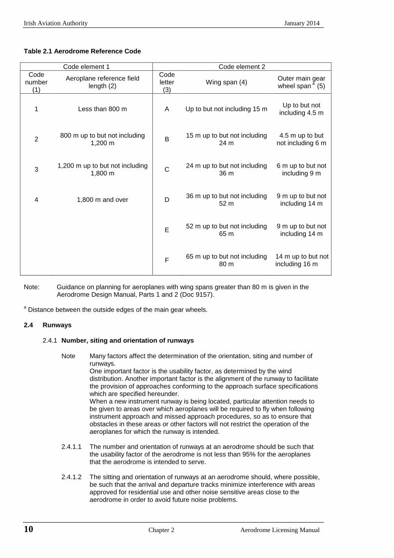
2.3.1 An aerodrome reference code containing two elements – a code number and a letter - which is selected for aerodrome planning purposes shall be determined in accordance with the characteristics of the aeroplane for which the aerodrome is intended.
2.3.2 The aerodrome reference code numbers and letters shall have the meanings assigned to
them in Table 2.1.
2.3.3 The code number for element 1 shall be determined from Table 2.1, Column 1, by selecting the code number corresponding to the highest value of the reference field lengths of the aeroplanes for which the runway is intended.
Note The determination of the aeroplane reference field length is solely for the selection of a
code number and is not intended to influence the actual runway length provided.
2.3.4 The code letter for element 2 shall be determined from Table 2.1, Column 3, by selecting the letter which corresponds to the greatest wing span or the greatest outer main wheel span, whichever gives the more demanding code letter, of the aeroplanes for which the facility is intended.
Note: Guidance to assist in determining the aerodrome reference code is given in the
Aerodrome Design Manual Parts 1 and 2 (Doc 9157).
Irish Aviation Authority January 2014
10 Chapter 2 Aerodrome Licensing Manual
Table 2.1 Aerodrome Reference Code
Code element 1 Code element 2
Code number
(1)
Aeroplane reference field length (2)
Code letter (3)
Wing span (4) Outer main gear wheel span
a (5)
1 Less than 800 m A Up to but not including 15 m
Up to but not
including 4.5 m
2 800 m up to but not including
1,200 m B
15 m up to but not including 24 m
4.5 m up to but
not including 6 m
3 1,200 m up to but not including
1,800 m C
24 m up to but not including 36 m
6 m up to but not
including 9 m
4 1,800 m and over D 36 m up to but not including
52 m
9 m up to but not including 14 m
E 52 m up to but not including
65 m
9 m up to but not including 14 m
F 65 m up to but not including
80 m
14 m up to but not including 16 m
Note: Guidance on planning for aeroplanes with wing spans greater than 80 m is given in the
Aerodrome Design Manual, Parts 1 and 2 (Doc 9157). a Distance between the outside edges of the main gear wheels.
2.4 Runways
2.4.1 Number, siting and orientation of runways
Note Many factors affect the determination of the orientation, siting and number of
runways. One important factor is the usability factor, as determined by the wind
distribution. Another important factor is the alignment of the runway to facilitate the provision of approaches conforming to the approach surface specifications which are specified hereunder.
When a new instrument runway is being located, particular attention needs to be given to areas over which aeroplanes will be required to fly when following instrument approach and missed approach procedures, so as to ensure that obstacles in these areas or other factors will not restrict the operation of the aeroplanes for which the runway is intended.
2.4.1.1 The number and orientation of runways at an aerodrome should be such that
the usability factor of the aerodrome is not less than 95% for the aeroplanes that the aerodrome is intended to serve.
2.4.1.2 The sitting and orientation of runways at an aerodrome should, where possible,
be such that the arrival and departure tracks minimize interference with areas approved for residential use and other noise sensitive areas close to the aerodrome in order to avoid future noise problems.
January 2014 Irish Aviation Authority
Aerodrome Licensing Manual Chapter 2 11
Note Guidance on how to address noise problems is provided in the Airport Planning Manual (Doc 9184), Part 2, and in Guidance on the Balanced Approach to Aircraft Noise Management (Doc 9829).
2.4.1.3 In the application of 2.4.1.1 it should be assumed that landing or take-off of aeroplanes is, in normal circumstances, precluded when the cross-wind component exceeds:
a) 37 km/h (20 kt) in the case of aeroplanes whose reference field length is1500 m or over, except that when poor runway braking action owing toinsufficient longitudinal coefficient of friction is experienced with somefrequency, a cross-wind component not exceeding 24 km/h (13 kt) shouldbe assumed;
b) 24 km/h (13 kt) in the case of aeroplanes whose reference field length is1200 m up to but not including 1500 m; and;
c) 19 km/h (10 kt) in the case of aeroplanes whose reference field length isless than 1200 m.
Note: In Annex 14, Attachment A, Section 1 guidance is given on factors affecting the calculation of the estimate of the usability factor and allowances which may have to be made to take account of the effect of unusual circumstances.
2.4.1.4 The selection of data to be used for the calculation of the usability factor should be based on reliable wind distribution statistics that extend over as long a period as possible, preferably of not less than five years. The observations used should be made at least eight times daily and spaced at equal intervals of time.
2.4.1.5 The maximum mean cross-wind components given in para.2.4.1.3 refer to normal circumstances. There are some factors that may require a reduction in those values to be taken into account at a particular aerodrome. These include;
- prevalence and nature of gusts; - prevalence and nature of turbulence; - the availability of a secondary runway; - width of runways; - runway surface conditions; and; - strength of the wind associated with the limiting cross-wind component.
Account may also need to be taken of the frequency of low visibility and/or low cloud base and accompanying wind direction and speed. Further information is provided in Annex 14, Attachment A, Section 1.
2.4.2 Location of threshold
2.4.2.1 A threshold should normally be located at the extremity of a runway, unless operational considerations justify the choice of another location.
2.4.2.2 When it is necessary to displace a threshold either permanently or temporarily from its normal location, account should be taken of the various factors which may have a bearing on the location of the threshold. Where this displacement is due to an unserviceable runway condition, a cleared and graded area of at least 60 m in length should be available between the unserviceable area and the displaced threshold. Additional distance should also be provided to meet the requirements of the runway end safety area as appropriate.
Note: Guidance on factors which may be considered in the determination of the location of the threshold is given in Annex 14, Attachment A, Section 11.

Irish Aviation Authority January 2014
12 Chapter 2 Aerodrome Licensing Manual
2.4.3 Actual length of runways
2.4.3.1 Except as provided in 2.4.3.3 the actual runway length to be provided for a primary runway should be adequate to meet the operational requirements of the aeroplanes for which the runway is intended and should be not less than the longest length determined by applying the corrections for local conditions to the operations and performance characteristics of the relevant aeroplanes.
Notes: 1 This specification does not necessarily mean providing for operations by the
critical aeroplane at its maximum mass.
2 Both take-off and landing requirements need to be considered when determining the length of runway to be provided and the need for operations to be conducted in both directions of the runway.
3 Local conditions that may need to be considered include elevation,
temperature, runway slope, humidity and the runway surface characteristics.
4 When performance data on aeroplanes for which the runway is intended are not known, guidance on the determination of the actual length of a primary runway by application of general correction factors is given in the Aerodrome Design Manual, Part 1 (Doc 9157).
2.4.3.2 The length of a secondary runway should be determined similarly to primary
runways except that it only needs to be adequate for those aeroplanes which require the use of that secondary runway in addition to the other runway(s) in order to obtain a usability factor of at least 95%.
2.4.3.3 Where a runway is associated with a stopway or clearway an actual runway
length less than that resulting from application of 2.4.3.1 or 2.4.3.2 as appropriate may be considered satisfactory, but in such a case any combination of runway, stopway and clearway provided should permit compliance with the operational requirements for take-off and landing of the aeroplanes the runway is intended to serve.
Note: Guidance on the use of stopways and clearways is given in Annex
14, Attachment A, Section 2.
2.4.4 Width of runways
2.4.4.1 The width of a runway should be not less than the appropriate dimension
specified in the following tabulation:
Table 2.2 Runway widths
a The width of a precision approach runway should be not less than 30 m where the code
number is 1 or 2.
Code Letter
Code Number
A B C D E F
1a 18 m 18 m 23 m -- --
2 a 23 m 23 m 30 m -- --
3 30 m 30 m 30 m 45 m --
4 -- -- 45 m 45 m 45 m 60 m
January 2014 Irish Aviation Authority
Aerodrome Licensing Manual Chapter 2 13
Notes: 1 The combinations of code numbers and letter for which widths are specified
have been developed for typical aeroplane characteristics. 2 Factors affecting runway width are given in the Aerodrome Design Manual,
(Doc 9157) Part 1.
2.4.4.2 Where parallel non-instrument runways are intended for simultaneous use, the minimum distance between their centre lines should be: - 210m where the higher code number is 3 or 4; - 150 m where the higher code number is 2; - 120 m where the higher code number is 1.
Note: Procedures for wake turbulence categorisation of aircraft and wake turbulence
separation minima are contained in the Procedures for Air Navigation Services – Air Traffic Management (PANS-ATM), Doc 4444, Chapter 4, para 4.9 and Chapter 5, para 5.8, respectively.
2.4.4.3 Where parallel instrument runways are intended for simultaneous use subject to
conditions specified in the PANS-ATM (Doc 4444) and the PANS-OPS (Doc 8168), Volume 1 the minimum distance between their centre lines should be: - 1,035 m for independent parallel approaches; - 915 m for dependent parallel approaches; - 760 m for independent parallel departures; - 760 m for segregated parallel operations; except that: a) for segregated parallel operations the specified minimum distance may
be decreased by 30 m for each 150 m that the arrival runway is staggered toward the arriving aircraft, to a minimum of 300 m; and should be increased by 30 m for each 150 m that the arrival runway is staggered away from the arriving aircraft:
b) for independent parallel approaches, combinations of minimum distances and associated conditions other than those specified in the PANS-ATM (Doc 4444), may be applied when it is determined that such combinations would not adversely affect the safety of aircraft operations.
Note: Procedures and facilities requirements for simultaneous operations on parallel
or near-parallel instrument runways are contained in the PANS-ATM (Doc 4444), Chapter 6 and the PANS-OPS (Doc 8168), Volume 1, Part VII and Volume II, Parts II and III and relevant guidance is contained in the Manual of Simultaneous Operations on Parallel or Near-Parallel Instrument Runways (Doc 9643).
2.4.5 Longitudinal Slopes
2.4.5.1 The slope computed by dividing the difference between the maximum and
minimum elevation along the runway centre line by the length of the runway should not exceed:
1% where the code number is 3 or 4; and
2% where the code number is 1 or 2.
2.4.5.2 Along no portion of a runway should the longitudinal slope exceed:
1.25% where the code number is 4, except that for the first and last quarter of the length of the runway the longitudinal slope should not exceed 0.8%;
Irish Aviation Authority January 2014
14 Chapter 2 Aerodrome Licensing Manual
1.5% where the code number is 3, except that for the first and last quarter of the length of a precision approach runway category II or III the longitudinal slope should not exceed 0.8%; and
2% where the code number is 1 or 2.
2.4.5.3 Where slope changes cannot be avoided, a slope change between two consecutive slopes should not exceed:
1.5% where the code number is 3 or 4;
2.0% where the code number is 1 or 2.
Note: Guidance on slope changes before a runway is given in Annex 14, Attachment A, Section 4.
2.4.5.4 The transition from one slope to another should be accomplished by a curved surface with a rate of change not exceeding:
0.1% per 30 m, (minimum radius of curvature of 30 000 m) where the code number is 4,
0.2% per 30 m, (minimum radius of curvature of 15 000 m) where the code number is 3,
0.4% per 30 m, (minimum radius of curvature of 7 500 m) where the code number is 1 or 2.
2.4.6 Sight Distance
2.4.6.1 Where slope changes cannot be avoided, they should be such that there will be an unobstructed line of sight from:
a) any point 3 m above the runway to all other points 3 m above the runway
within a distance of at least half the length of the runway where the code letter is C, D, E or F;
b) any point 2 m above the runway to all other points 2 m above the runway within a distance of at least half the length of the runway where the code letter is B; and
c) any point 1.5 m above the runway to all other points 1.5 m above the runway within a distance of at least half the length of the runway where the code letter is A.
Note: Consideration will have to be given to providing an
unobstructed line of sight over the entire length of a single runway where a full-length parallel taxiway is not available. Where an aerodrome has intersecting runways, additional criteria on the line of sight of the intersecting area would need to be considered for operational safety. See the Aerodrome Design Manual, Part 1 (Doc 9157).
2.4.7 Distance between slope changes
2.4.7.1 Undulations or appreciable changes in slopes located close together along a
runway should be avoided. The distance between the points of intersection of two successive slope changes should not be less than:
a) the sum of the absolute numerical values of the corresponding slope changes multiplied by:
30 000 m where the code number is 4;
15 000 m where the code number is 3 and
5 000 m where the code number is 1 or 2; or
b) 45 m; whichever is greater.
January 2014 Irish Aviation Authority
Aerodrome Licensing Manual Chapter 2 15
Note: Guidance on implementing this specification is given in Annex 14, Attachment A, Section 4.
2.4.8 Transverse Slopes
2.4.8.1 To promote the most rapid drainage of water, the runway surface should if practicable, be cambered except where a single crossfall from high to low in the direction of the wind most frequently associated with rain would ensure rapid drainage. The transverse slope should ideally be:
1.5% where the code letter is C, D, E or F and
2.0% where the code letter is A or B:
but, in any event should not exceed 1.5% or 2% as applicable nor be less than 1% except at runway or taxiway intersections where flatter slopes may be necessary.
For a cambered surface the transverse slope on each side of the centre line should be symmetrical.
Note: On wet runways in cross wind conditions, the problem of aquaplaning is apt to be accentuated. In Annex 14, Attachment A, Section 7, information is given concerning the problem and other relevant factors.
2.4.8.2 The transverse slope should be substantially the same throughout the length of the runway except at an intersection with another runway or a taxiway where an even transition should be provided taking account of the need for adequate drainage.
Note: Guidance on transverse slope is given in Aerodrome Design Manual, Part 3 (Doc 9157).
2.4.9 Strength of Runways
2.4.9.1 A runway should be capable of withstanding the traffic of aeroplanes the runway is intended to serve.
2.4.10 Surface of Runways
2.4.10.1 The surface of a runway shall be constructed without irregularities that would result in loss of friction characteristics or otherwise adversely affect the take-off or landing of an aeroplane.
Notes: 1 Surface irregularities may adversely affect the take-off or landing of an aeroplane by causing excessive bouncing, pitching, vibration or other difficulties in the control of an aeroplane. 2 Guidance on design tolerances and other information is given in the Aerodrome Design Manual Part 3 (Doc 9157) and in Annex 14, Attachment A, Section 5.
2.4.10.2 A paved runway shall be so constructed or resurfaced as to provide surface friction
characteristics at or above the minimum friction level specified in Table 2.3. The surface of a paved runway should be evaluated when constructed or resurfaced to determine that the surface friction characteristics achieve the design objectives
2.4.10.3 The aerodrome authority should agree with the Authority the equipment they intend to use for measuring the frictional characteristics of runways.
Irish Aviation Authority January 2014
16 Chapter 2 Aerodrome Licensing Manual
2.4.10.4 On paved runways (greater than 1,000 metres in length) of aerodromes licensed for
public use, measurements of the surface coefficient of friction are to be made. These measurements should be made with a continuous friction measuring device using self wetting features and a depth of water of 1 mm.
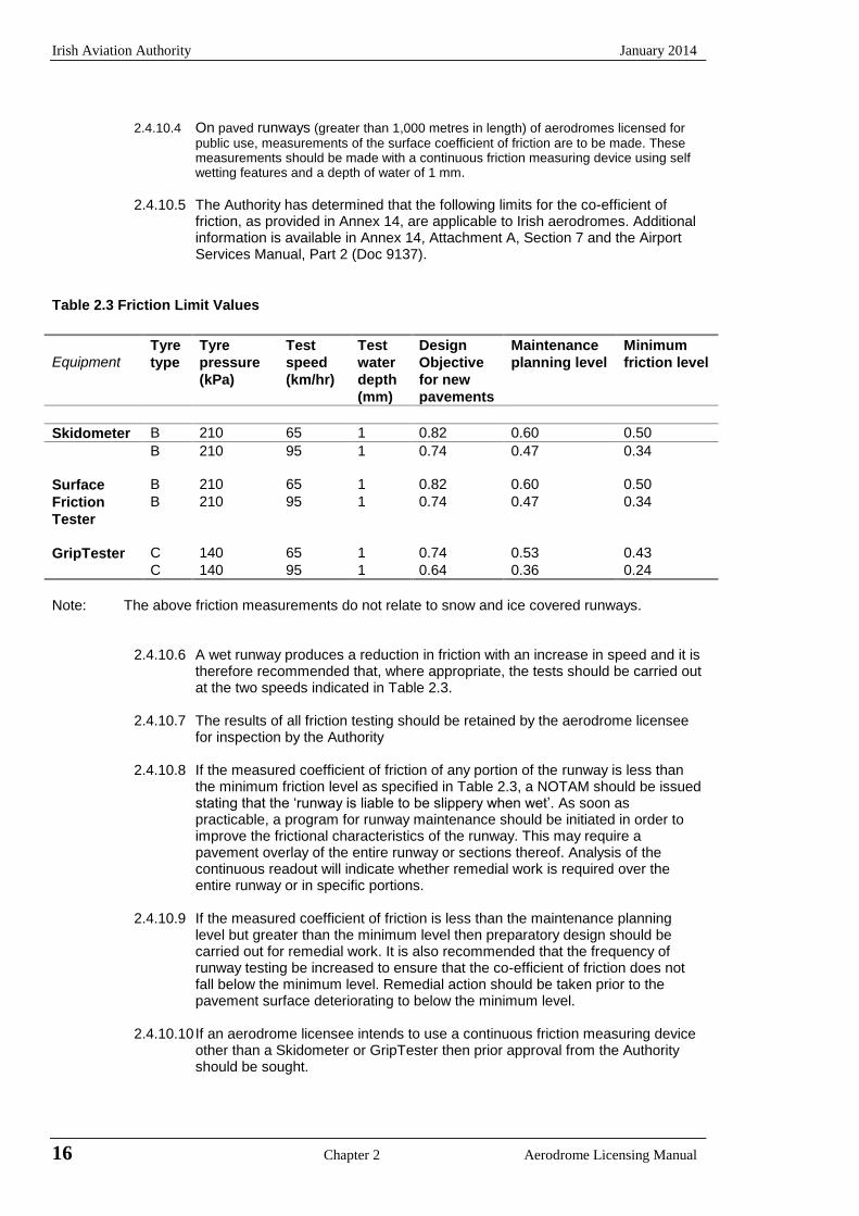
2.4.10.5 The Authority has determined that the following limits for the co-efficient of
friction, as provided in Annex 14, are applicable to Irish aerodromes. Additional information is available in Annex 14, Attachment A, Section 7 and the Airport Services Manual, Part 2 (Doc 9137).
Table 2.3 Friction Limit Values
Equipment Tyre
type
Tyre
pressure
(kPa)
Test
speed
(km/hr)
Test
water
depth
(mm)
Design
Objective
for new
pavements
Maintenance
planning level
Minimum
friction level
Skidometer B 210 65 1 0.82 0.60 0.50
B 210 95 1 0.74 0.47 0.34
Surface B 210 65 1 0.82 0.60 0.50
Friction
Tester
B 210 95 1 0.74 0.47 0.34
GripTester C 140 65 1 0.74 0.53 0.43
C 140 95 1 0.64 0.36 0.24
Note: The above friction measurements do not relate to snow and ice covered runways.
2.4.10.6 A wet runway produces a reduction in friction with an increase in speed and it is therefore recommended that, where appropriate, the tests should be carried out at the two speeds indicated in Table 2.3.
2.4.10.7 The results of all friction testing should be retained by the aerodrome licensee
for inspection by the Authority 2.4.10.8 If the measured coefficient of friction of any portion of the runway is less than
the minimum friction level as specified in Table 2.3, a NOTAM should be issued stating that the ‘runway is liable to be slippery when wet’. As soon as practicable, a program for runway maintenance should be initiated in order to improve the frictional characteristics of the runway. This may require a pavement overlay of the entire runway or sections thereof. Analysis of the continuous readout will indicate whether remedial work is required over the entire runway or in specific portions.
2.4.10.9 If the measured coefficient of friction is less than the maintenance planning
level but greater than the minimum level then preparatory design should be carried out for remedial work. It is also recommended that the frequency of runway testing be increased to ensure that the co-efficient of friction does not fall below the minimum level. Remedial action should be taken prior to the pavement surface deteriorating to below the minimum level.
2.4.10.10 If an aerodrome licensee intends to use a continuous friction measuring device
other than a Skidometer or GripTester then prior approval from the Authority should be sought.
January 2014 Irish Aviation Authority
Aerodrome Licensing Manual Chapter 2 17
2.4.10.11 It should be noted that the use of decelerometers, such as the Tapley meter, is restricted to measurements of braking action on runways covered with snow and ice.
2.4.10.12 In order to identify a runway pavement surface which may be deteriorating in
terms of the co-efficient of friction, it is recommended that the following minimum testing frequencies should be adopted. Where a pavement or portion thereof is below the maintenance planning level then the frequency of measurement may need to be increased to ensure that the measured coefficient does not fall below the specified minimum friction level.
Table 2.4 Minimum Testing Frequencies
Average no. of daily movements per
runway
Frequency of Measurement of co-efficient
of friction
Less than 100 12 months 100 – 450 6 months
Greater than 450 2 months
2.4.10.13 In order to assess the coefficient of friction of the pavement under operational
conditions, it is recommended that additional tests be conducted under natural conditions, particularly if there are areas of standing water along the runway.
2.4.10.14 When the surface is grooved or scored, the grooves or scoring should be either
perpendicular to the runway centre line or parallel to non-perpendicular transverse joints where applicable.
Note: Guidance on methods for improving the runway surface texture is given in the
Aerodrome Design Manual, Part 3 (Doc 9157).
2.4.4.14 The average surface texture depth of a new surface should be not less than 1.0 mm.
Note 1 Macrotexture and microtexture are taken into consideration in order to provide
the required surface friction characteristics. Guidance on surface design is given in Attachment A, Section 8.
Note 2 Guidance on methods used to measure surface texture is given in the Airport Services Manual (Doc 9137), Part 2.
Note 3 Guidance on design and methods for improving surface texture is given in the Aerodrome Design Manual (Doc 9157), Part 3.
2.4.11 Runway Shoulders
2.4.11.1 With some large aeroplanes the wing-mounted engines may over hang the
runway edge and there is a risk of jet blast eroding the surface adjacent to the runway. This may cause dust and the possible ingestion of debris by the engines. Also, strong cross winds may result in significant deviation from the runway centreline. To overcome these difficulties runway shoulders should be provided for runways:
a) where the code letter is D or E and the runway width is less than 60 m;
and b) where the code letter is F.
2.4.11.2 The runway shoulders should extend symmetrically on each side of the runway
so that the overall width of runway and its shoulders is not less than:
a) 60 m where the code letter is D or E; and b) 75 m where the code letter is F.
Irish Aviation Authority January 2014
18 Chapter 2 Aerodrome Licensing Manual
2.4.11.3 The surface of the shoulder that abuts the runway should be flush with the surface of the runway and its transverse slope should not exceed 2.5%.
2.4.11.4 A runway shoulder should be prepared and constructed so as to be capable, in
the event of an aeroplane running off the runway, of supporting the aeroplane without inducing structural damage to the aeroplane and of supporting ground vehicles which may operate on the shoulder.
Note: Guidance on the characteristics, strength and treatment of runway shoulders is
given in Annex 14, Attachment A, Section 8 and the Aerodrome Design Manual, Part 1 (Doc 9157).
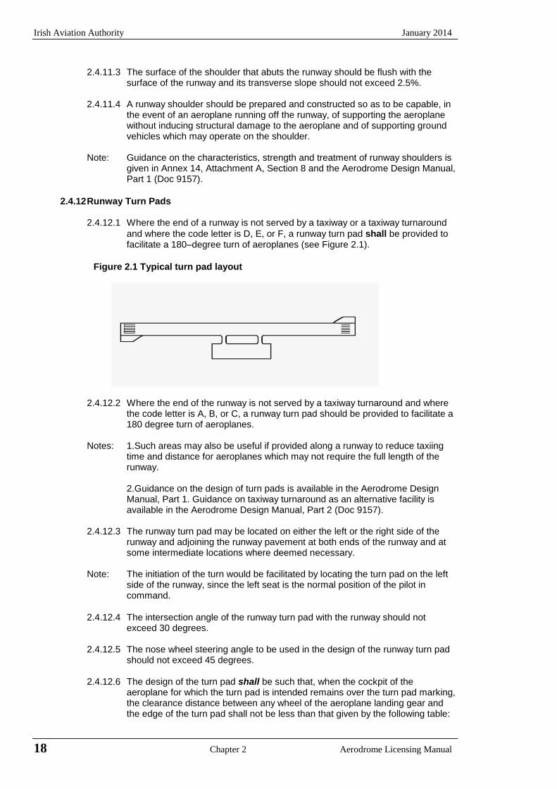
2.4.12 Runway Turn Pads
2.4.12.1 Where the end of a runway is not served by a taxiway or a taxiway turnaround
and where the code letter is D, E, or F, a runway turn pad shall be provided to facilitate a 180–degree turn of aeroplanes (see Figure 2.1).
Figure 2.1 Typical turn pad layout
2.4.12.2 Where the end of the runway is not served by a taxiway turnaround and where
the code letter is A, B, or C, a runway turn pad should be provided to facilitate a 180 degree turn of aeroplanes.
Notes: 1.Such areas may also be useful if provided along a runway to reduce taxiing
time and distance for aeroplanes which may not require the full length of the runway. 2.Guidance on the design of turn pads is available in the Aerodrome Design Manual, Part 1. Guidance on taxiway turnaround as an alternative facility is available in the Aerodrome Design Manual, Part 2 (Doc 9157).
2.4.12.3 The runway turn pad may be located on either the left or the right side of the
runway and adjoining the runway pavement at both ends of the runway and at some intermediate locations where deemed necessary.
Note: The initiation of the turn would be facilitated by locating the turn pad on the left
side of the runway, since the left seat is the normal position of the pilot in command.
2.4.12.4 The intersection angle of the runway turn pad with the runway should not
exceed 30 degrees.
2.4.12.5 The nose wheel steering angle to be used in the design of the runway turn pad should not exceed 45 degrees.
2.4.12.6 The design of the turn pad shall be such that, when the cockpit of the
aeroplane for which the turn pad is intended remains over the turn pad marking, the clearance distance between any wheel of the aeroplane landing gear and the edge of the turn pad shall not be less than that given by the following table:
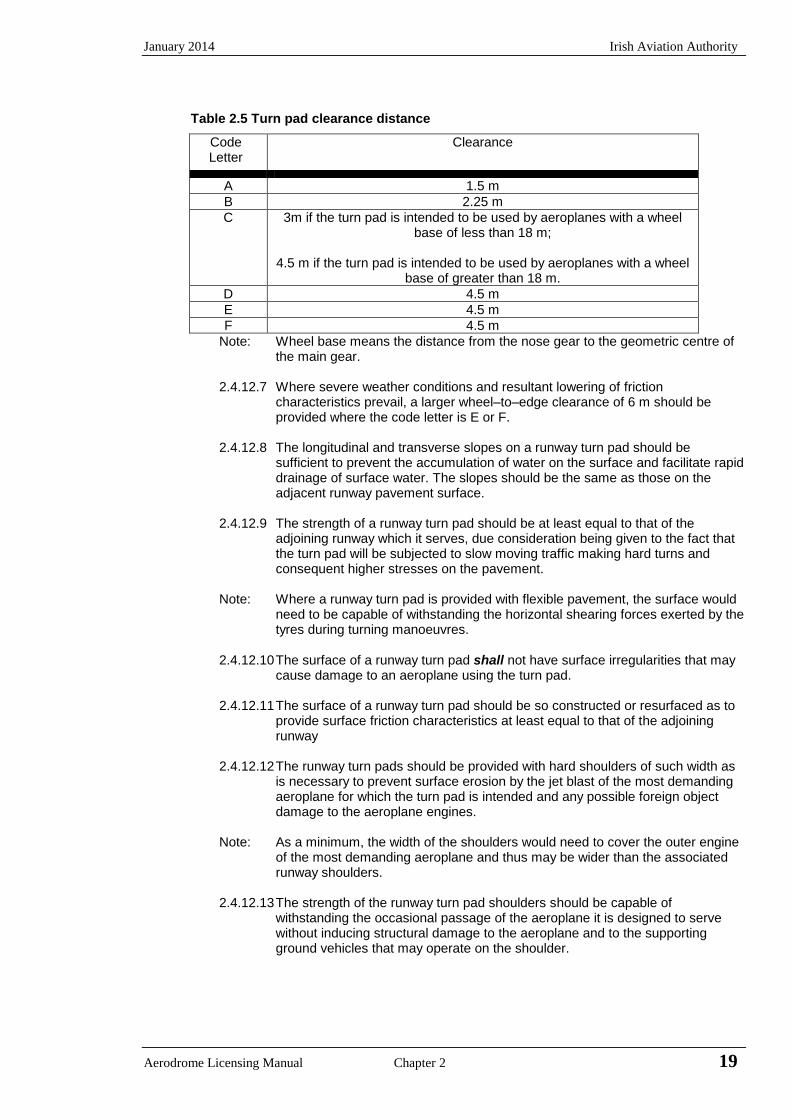
January 2014 Irish Aviation Authority
Aerodrome Licensing Manual Chapter 2 19
Table 2.5 Turn pad clearance distance
Code Letter
Clearance
A 1.5 m
B 2.25 m
C 3m if the turn pad is intended to be used by aeroplanes with a wheel base of less than 18 m;
4.5 m if the turn pad is intended to be used by aeroplanes with a wheel
base of greater than 18 m.
D 4.5 m
E 4.5 m
F 4.5 m
Note: Wheel base means the distance from the nose gear to the geometric centre of the main gear.
2.4.12.7 Where severe weather conditions and resultant lowering of friction
characteristics prevail, a larger wheel–to–edge clearance of 6 m should be provided where the code letter is E or F.
2.4.12.8 The longitudinal and transverse slopes on a runway turn pad should be
sufficient to prevent the accumulation of water on the surface and facilitate rapid drainage of surface water. The slopes should be the same as those on the adjacent runway pavement surface.
2.4.12.9 The strength of a runway turn pad should be at least equal to that of the
adjoining runway which it serves, due consideration being given to the fact that the turn pad will be subjected to slow moving traffic making hard turns and consequent higher stresses on the pavement.
Note: Where a runway turn pad is provided with flexible pavement, the surface would
need to be capable of withstanding the horizontal shearing forces exerted by the tyres during turning manoeuvres.
2.4.12.10 The surface of a runway turn pad shall not have surface irregularities that may cause damage to an aeroplane using the turn pad.
2.4.12.11 The surface of a runway turn pad should be so constructed or resurfaced as to
provide surface friction characteristics at least equal to that of the adjoining runway
2.4.12.12 The runway turn pads should be provided with hard shoulders of such width as
is necessary to prevent surface erosion by the jet blast of the most demanding aeroplane for which the turn pad is intended and any possible foreign object damage to the aeroplane engines.
Note: As a minimum, the width of the shoulders would need to cover the outer engine
of the most demanding aeroplane and thus may be wider than the associated runway shoulders.
2.4.12.13 The strength of the runway turn pad shoulders should be capable of
withstanding the occasional passage of the aeroplane it is designed to serve without inducing structural damage to the aeroplane and to the supporting ground vehicles that may operate on the shoulder.
Irish Aviation Authority January 2014
20 Chapter 2 Aerodrome Licensing Manual
2.4.13 Runway Strips
2.4.13.1 A runway and any associated stopways shall be included in a strip. The purpose
of the Strip is to:
a) reduce the risk of damage to an aeroplane running off the runway by providing a graded area which meets specified longitudinal and transverse slopes, and bearing strength requirements; and
b) protect aeroplanes flying over it during landing, missed approach or take-
off by providing an area which is cleared of obstacles except permitted aids to navigation.
Ideally the whole of a runway strip should be clear of obstacles but in practice it is recognised that the strip facilitates the installation of visual, radio and radar aids, and some of these cannot perform their function if they are sited outside the runway strip. Equipment essential to an instrument approach, landing or missed approach is permitted within the runway strip subject to the conditions detailed in 2.4.14.8. Drainage channels, catch pits and other essential design features at aerodromes should not constitute hazards to aeroplanes. Wherever possible, items which are not required to be at ground level should be buried to a depth of not less than 0.45 m. Within the graded area of the runway strip constructions such as plinths, runway ends, paved taxiway edges, etc should be so constructed as to avoid presenting a buried vertical face to aircraft wheels in soft ground conditions in any direction that an aircraft is likely to approach. To eliminate a buried vertical face, a sloping apron should be provided which extends from the top of the construction to not less than 0.3 m below ground level. Construction and the materials to be used will depend on the soil conditions.
2.4.13.2 A strip shall extend before the threshold and beyond the end of the runway or stopway for a distance of at least:
- 60 m where the code number is 2, 3 or 4, - 60 m where the code number is 1 and the runway is an instrument runway, - 30 m where the code number is 1 and the runway is a non-instrument one.
2.4.13.3 A strip including a precision approach runway shall, wherever practicable, extend laterally to a distance of at least:
- 150 m where the code number is 3 or 4; and - 75 m where the code number is 1 or 2;
on each side of the centre line of the runway and its extended centre line throughout the length of the strip.
2.4.13.4 A strip including a non-precision approach runway should extend laterally to a
distance of at least:
- 150 m where the code number is 3 or 4, and - 75 m where the code number is 1 or 2.
on each side of the centre line of the runway and its extended centre line throughout the length of the strip.
2.4.13.5 A strip including a non-instrument runway should extend laterally on each side
of the centre line of the runway and its extended centre line throughout the length of the strip to a distance of at least;
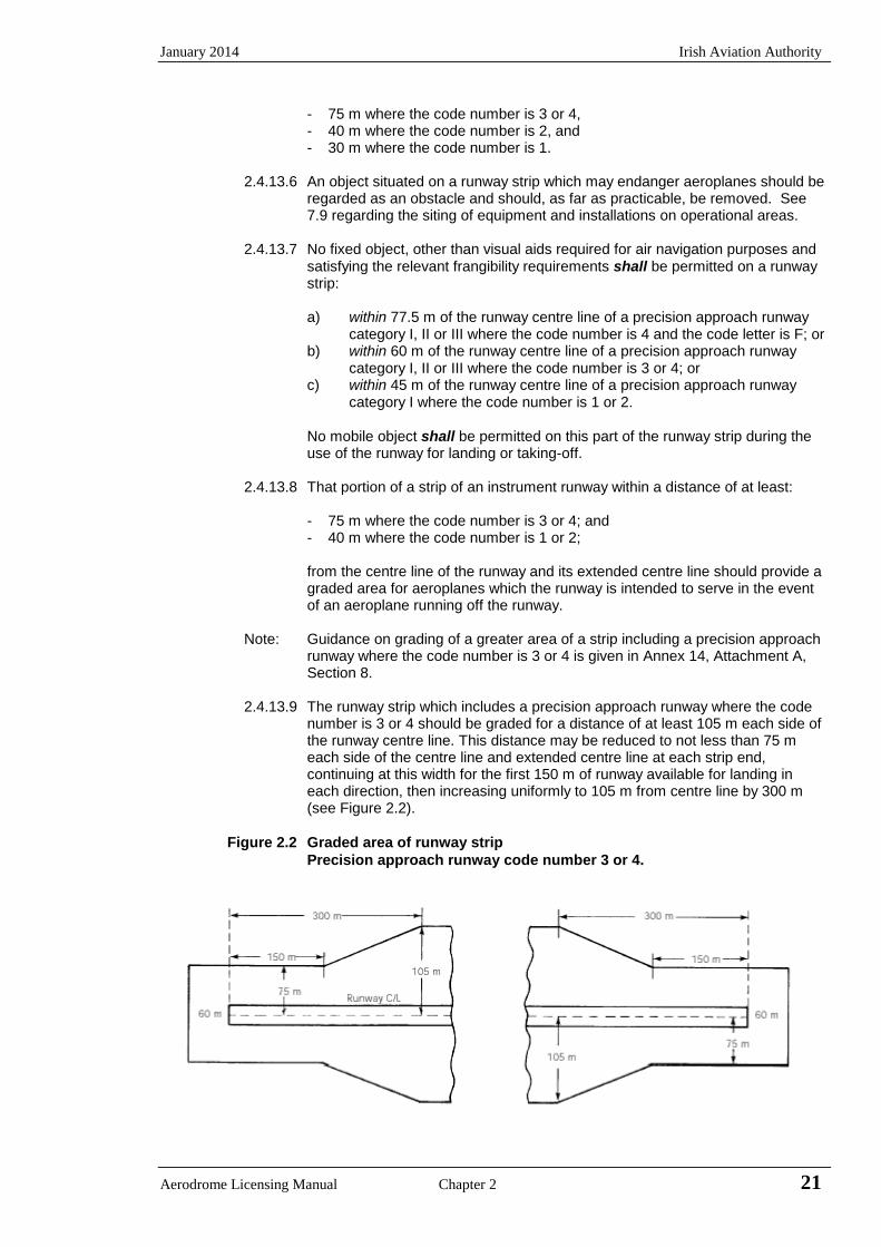
January 2014 Irish Aviation Authority
Aerodrome Licensing Manual Chapter 2 21
- 75 m where the code number is 3 or 4, - 40 m where the code number is 2, and - 30 m where the code number is 1.
2.4.13.6 An object situated on a runway strip which may endanger aeroplanes should be
regarded as an obstacle and should, as far as practicable, be removed. See 7.9 regarding the siting of equipment and installations on operational areas.
2.4.13.7 No fixed object, other than visual aids required for air navigation purposes and
satisfying the relevant frangibility requirements shall be permitted on a runway strip:
a) within 77.5 m of the runway centre line of a precision approach runway
category I, II or III where the code number is 4 and the code letter is F; or b) within 60 m of the runway centre line of a precision approach runway
category I, II or III where the code number is 3 or 4; or c) within 45 m of the runway centre line of a precision approach runway
category I where the code number is 1 or 2.
No mobile object shall be permitted on this part of the runway strip during the use of the runway for landing or taking-off.
2.4.13.8 That portion of a strip of an instrument runway within a distance of at least:
- 75 m where the code number is 3 or 4; and - 40 m where the code number is 1 or 2;
from the centre line of the runway and its extended centre line should provide a graded area for aeroplanes which the runway is intended to serve in the event of an aeroplane running off the runway.
Note: Guidance on grading of a greater area of a strip including a precision approach runway where the code number is 3 or 4 is given in Annex 14, Attachment A, Section 8.
2.4.13.9 The runway strip which includes a precision approach runway where the code
number is 3 or 4 should be graded for a distance of at least 105 m each side of the runway centre line. This distance may be reduced to not less than 75 m each side of the centre line and extended centre line at each strip end, continuing at this width for the first 150 m of runway available for landing in each direction, then increasing uniformly to 105 m from centre line by 300 m (see Figure 2.2).
Figure 2.2 Graded area of runway strip
Precision approach runway code number 3 or 4.

Irish Aviation Authority January 2014
22 Chapter 2 Aerodrome Licensing Manual
2.4.13.10 The runway strip which includes a non-instrument runway should be graded on
each side of the runway centre line and extended centre line for a distance of at least:
- 75 m where the code number is 3 or 4; - 40 m where the code number is 2; and - 30 m where the code number is 1.
2.4.13.11 The surface of that portion of a strip that abuts a runway, shoulder or stopway
shall be flush with the surface of the runway, shoulder or stopway.
2.4.13.12 That portion of a strip to at least 30 m before the threshold should be prepared against blast erosion in order to protect a landing aeroplane from the danger of an exposed edge. Where these areas have paved surfaces, they should be able to withstand the occasional passage of the critical aeroplane for runway pavement design.
Note: The area adjacent to the end of a runway may be referred to as a blast pad.
2.4.13.13 A longitudinal slope along that portion of a strip to be graded should not exceed:
- 1.5 % where the code number is 4; - 1.75 % where the code number is 3; and - 2.0 % where the code number is 1 or 2.
2.4.13.14 Slope changes on that portion of a strip to be graded should be as gradual as
practicable and abrupt changes or sudden reversals of slopes avoided. 2.4.13.15 Transverse slopes on that portion of the strip to be graded should be adequate
to prevent the accumulation of water on the surface but should not exceed: - 2.5% where the code number is 3 or 4; and - 3.0% where the code number is 1 or 2, except that to facilitate drainage the slope for the first 3 m outward from the runway, shoulder or stopway edge should be negative as measured in the direction away from the runway and may be as great as 5.0%.
2.4.13.16 The transverse slopes of any portion of a strip to be graded should not exceed
an upward slope of 5.0% as measured in the direction away from the runway.
2.4.13.17 That portion of the runway strip of an instrument runway within the distance of
at least:
- 75 m where the code number is 3 or 4, and - 40 m where the code number is 1 or 2,
from the centre line of the runway and its extended centre line should be so prepared or constructed as to minimise hazards arising from differences in load bearing capacity to aeroplanes which the runway is intended to serve in the event of an aeroplane running off the runway.
January 2014 Irish Aviation Authority
Aerodrome Licensing Manual Chapter 2 23
2.4.13.18 That portion of the runway strip containing a non-instrument runway within a distance of at least;
- 75 m where the code number is 3 or 4, - 40 m where the code number is 2, and - 30 m where the code number is 1,
from the centre line of the runway and its extended centre line should be so prepared or constructed as to minimise hazards arising from differences in load bearing capacity to aeroplanes which the runway is intended to serve in the event of an aeroplane running off the runway.
Note: Guidance on the preparation of a runway strip is given in the Aerodrome Design Manual, Part 1 (Doc 9157).
2.4.14 Runway End Safety Areas
2.4.14.1 A runway end safety area (RESA) is an area symmetrical about an extended runway centre line adjacent to the end of the strip primarily intended to reduce the risk of damage to an aeroplane undershooting or overrunning the runway. A runway end safety area shall be provided at each end of a runway strip where:
- the code number is 3 or 4; and - the code number is 1 or 2 and the runway is an instrument one.
Note: Guidance on runway end safety areas is given in Annex 14, Attachment A, Section 10.
2.4.14.2 A runway end safety area shall extend from the end of a runway strip to a distance of at least 90 m.
If an arresting system is installed, the above length may be reduced, based on the design specification of the system, subject to acceptance by the Authority.
Note Guidance on arresting systems is given in annex 14, Attachment A, Section 10.
2.4.14.3 A runway end safety area should, as far as practicable, extend from the end of the runway strip to a distance of at least:
- 240 m where the code number is 3 or 4; or a reduced length when an arresting system is installed; and,
- 120 m where the code number is 1 or 2, and the runway is an instrument one; or a reduced length when an arresting system is installed; and
- 30 m where the code number is 1 or 2 and the runway is a non-instrument one.
2.4.14.4 The width of a runway end safety area shall be at least twice that of the associated runway.
2.4.14.5 The width of a runway end safety area should, wherever practicable, be equal to that of the graded portion of the associated runway strip.
2.4.14.6 An object situated on a runway end safety area, which may endanger aeroplanes, should be regarded as an obstacle and should, as far as practicable, be removed.
2.4.14.7 A runway end safety area should provide a cleared and graded area for aeroplanes that the runway is intended to serve in the event of an aeroplane undershooting or overrunning the runway.
Irish Aviation Authority January 2014
24 Chapter 2 Aerodrome Licensing Manual
Note: The surface of the ground in the runway end safety area does not need to be prepared to the same quality as the runway strip. See, however, 2.4.13.15.
2.4.14.8 The slopes of a runway end safety should be such that no part of the runway end safety area penetrates the approach or take-off climb surface.
2.4.14.9 The longitudinal slopes of a runway end safety area should not exceed a downward slope of 5%. Longitudinal slope changes should be as gradual as practicable and abrupt changes or sudden reversals of slopes avoided.
2.4.14.10 The transverse slopes of a runway end safety area should not exceed an upward or downward slope of 5%. Transitions between differing slopes should be as gradual as practicable.
2.4.14.11 If the requisite ground is not available, the runway end safety areas can be provided by reducing the distances declared as available for landing and take-off. Where the terrain immediately beyond the end of the strip, whether in the control of the airport authority or not, can be improved by relatively simple measures such as levelling, the weakening of a fence, or the piping or filling of a ditch, such improvements should be made.
2.4.14.12 A runway end safety area should be so prepared or constructed as to reduce the risk of damage to an aeroplane undershooting or overrunning the runway, enhance aeroplane deceleration and facilitate the movement of rescue and fire-fighting vehicles.
Note: Guidance on the strength of a runway end safety area is given in Aerodrome Design Manual, Part 1 (Doc 9157).
2.4.15 Clearways
2.4.15.1 A clearway may extend outside the aerodrome boundary only if the aerodrome authority establishes such control that will ensure that the clearway will be kept free from obstacles or that the clearway plane will not be infringed.
2.4.15.2 The origin of a clearway should be at the end of the take-off run available.
2.4.15.3 The length of a clearway should not exceed half the length of the take-off run available.
2.4.15.4 A clearway should extend laterally to a distance of at least 75 m on each side of the extended centre line of the runway.
2.4.15.5 The ground in a clearway should not project above a plane having an upward slope of 1.25 % the lower limit of the plane being a horizontal line which;
(a) is perpendicular to the vertical plane containing the runway centre line, and
(b) passes through a point located on the runway centre line at the end of the take-off run available.
Note: Because of transverse or longitudinal slopes on a runway, shoulder or strip, in certain cases the lower limit of the clearway plane specified above may be below the corresponding elevation of the runway, shoulder or strip. It is not intended that these surfaces be graded to conform with the lower limit of the clearway plane nor is it intended that terrain or objects which are above the clearway plane beyond the end of the strip but below the level of the strip be removed unless it is considered they may endanger aeroplanes.
January 2014 Irish Aviation Authority
Aerodrome Licensing Manual Chapter 2 25
2.4.15.6 Abrupt upward changes in slope should be avoided when the slope on the ground in a clearway is relatively small or when the mean slope is upward. In such situations, in that portion of the clearway within a distance of 22.5 m or half the runway width whichever is the greater on each side of the extended centre line, the slopes, slope changes and the transition from runway to clearway should generally conform to those of the runway with which the clearway is associated.
2.4.15.7 An object situated on a clearway, which may endanger aeroplanes in the air, should be regarded as an obstacle and should be removed.
2.4.16 Stopways
2.4.16.1 A stopway is regarded as being provided for infrequent use and need not have the same bearing or wearing qualities as the runway with which it is associated. In some cases the natural surfaces will be adequate while in others some land drainage, ground grading, consolidation or even light paving may be required.
Note: Annex 14, Attachment A, Section 2 provides information on the use of stopways.
2.4.16.2 A stopway shall have the same width as the runway with which it is associated.
2.4.16.3 Slopes and changes in slope on a stopway, and the transition from a runway to a stopway should comply with the specifications of 2.4.5.1 to 2.4.8.1 for the runway with which the stopway is associated except that:
a) the limitation in 2.4.5.2 of 0.8 % slope for the first and last quarter of thelength of the runway need not be applied to the stopway; and
b) at the junction of the stopway and runway and along the stopway themaximum rate of slope change may be 0.3 % per 30 m (minimum radiusof curvature of 10,000 m) for a runway where the code number is 3 or 4.
2.4.16.4 A stopway should be prepared or constructed so as to be capable, in the event of an abandoned take-off, of supporting the aeroplane that the stopway is intended to serve without inducing structural damage to the aeroplane.
Note: Annex 14, Attachment A, Section 2 presents guidance relative to the support capability of a stopway.
2.4.16.5 The surface of a paved stopway shall be so constructed or resurfaced as to provide surface friction characteristics at or above those of the associated runway.
2.4.16.6 The friction characteristics of an unpaved stopway should not be substantially less than that of the runway with which the stopway is associated.
2.4.17 Radio Altimeter Operating Area
2.4.17.1 A radio altimeter operating area should be established in the pre-threshold area of a precision approach runway.
2.4.17.2 A radio altimeter operating area should extend before the threshold for a distance of at least 300 m.
2.4.17.3 A radio altimeter operating area should extend laterally on each side of the extended centre line of the runway, to a distance of 60 m, except that when special circumstances so warrant, the distance may be reduced to no less than 30 m if an aeronautical study indicates that such reduction would not effect the safety of operations of aircraft.
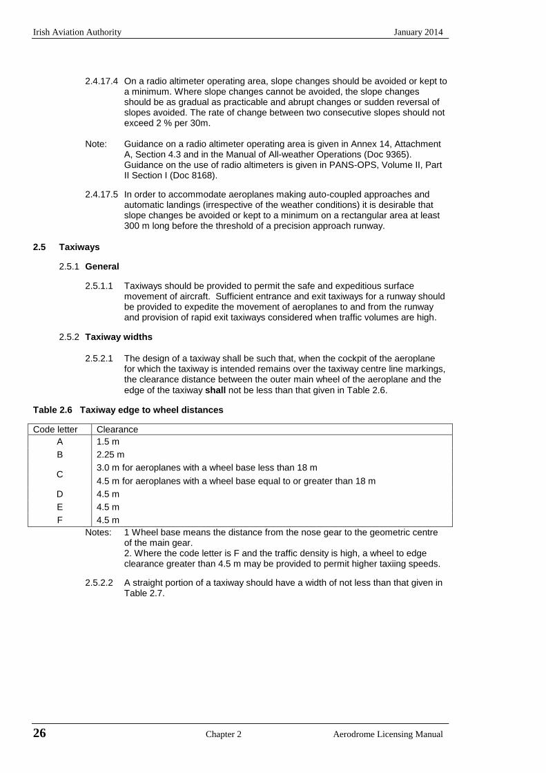
Irish Aviation Authority January 2014
26 Chapter 2 Aerodrome Licensing Manual
2.4.17.4 On a radio altimeter operating area, slope changes should be avoided or kept to a minimum. Where slope changes cannot be avoided, the slope changes should be as gradual as practicable and abrupt changes or sudden reversal of slopes avoided. The rate of change between two consecutive slopes should not exceed 2 % per 30m.
Note: Guidance on a radio altimeter operating area is given in Annex 14, Attachment A, Section 4.3 and in the Manual of All-weather Operations (Doc 9365). Guidance on the use of radio altimeters is given in PANS-OPS, Volume II, Part II Section I (Doc 8168).
2.4.17.5 In order to accommodate aeroplanes making auto-coupled approaches and automatic landings (irrespective of the weather conditions) it is desirable that slope changes be avoided or kept to a minimum on a rectangular area at least 300 m long before the threshold of a precision approach runway.
2.5 Taxiways
2.5.1 General
2.5.1.1 Taxiways should be provided to permit the safe and expeditious surface movement of aircraft. Sufficient entrance and exit taxiways for a runway should be provided to expedite the movement of aeroplanes to and from the runway and provision of rapid exit taxiways considered when traffic volumes are high.
2.5.2 Taxiway widths
2.5.2.1 The design of a taxiway shall be such that, when the cockpit of the aeroplane for which the taxiway is intended remains over the taxiway centre line markings, the clearance distance between the outer main wheel of the aeroplane and the
edge of the taxiway shall not be less than that given in Table 2.6.
Table 2.6 Taxiway edge to wheel distances
Code letter Clearance
A 1.5 m
B 2.25 m
C 3.0 m for aeroplanes with a wheel base less than 18 m
4.5 m for aeroplanes with a wheel base equal to or greater than 18 m
D 4.5 m
E 4.5 m
F 4.5 m
Notes: 1 Wheel base means the distance from the nose gear to the geometric centre of the main gear. 2. Where the code letter is F and the traffic density is high, a wheel to edgeclearance greater than 4.5 m may be provided to permit higher taxiing speeds.
2.5.2.2 A straight portion of a taxiway should have a width of not less than that given in Table 2.7.
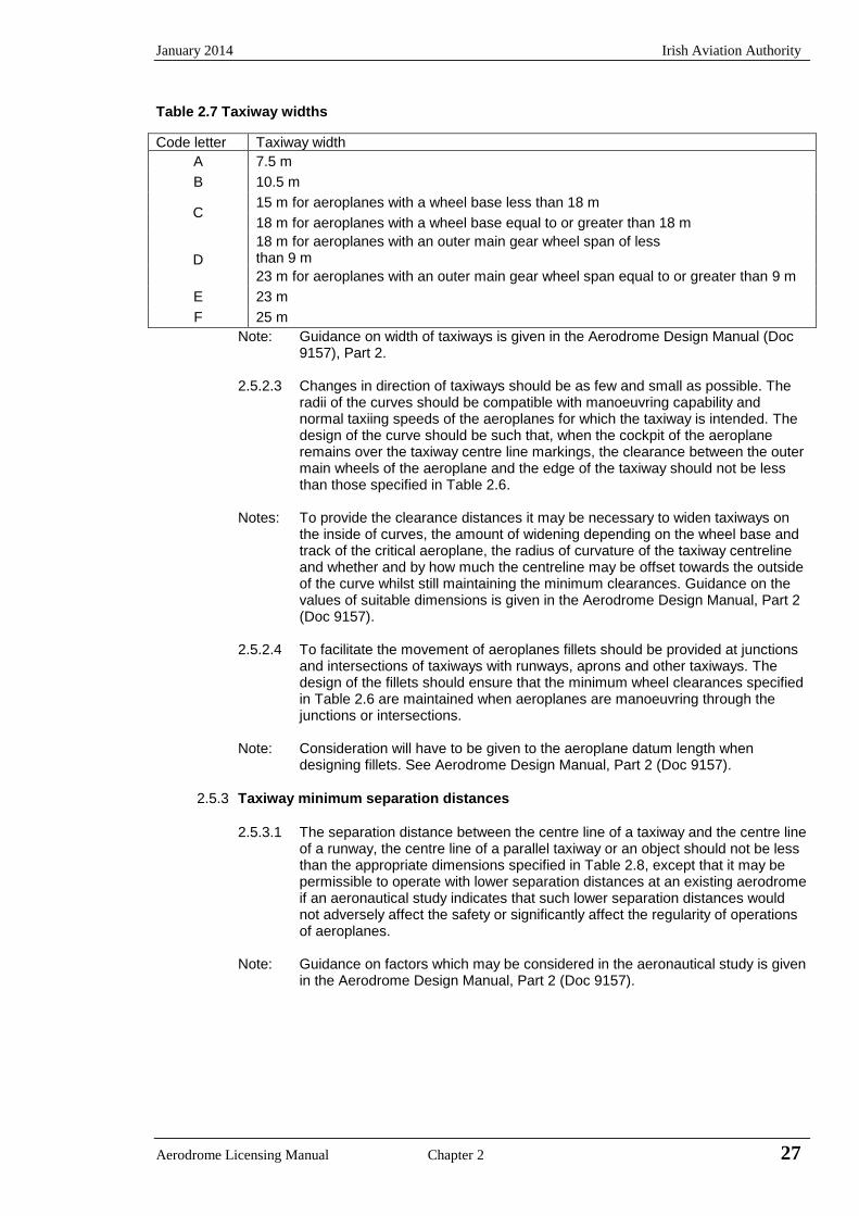
January 2014 Irish Aviation Authority
Aerodrome Licensing Manual Chapter 2 27
Table 2.7 Taxiway widths
Code letter Taxiway width
A 7.5 m
B 10.5 m
C 15 m for aeroplanes with a wheel base less than 18 m
18 m for aeroplanes with a wheel base equal to or greater than 18 m
D
18 m for aeroplanes with an outer main gear wheel span of less than 9 m
23 m for aeroplanes with an outer main gear wheel span equal to or greater than 9 m
E 23 m
F 25 m
Note: Guidance on width of taxiways is given in the Aerodrome Design Manual (Doc 9157), Part 2.
2.5.2.3 Changes in direction of taxiways should be as few and small as possible. The radii of the curves should be compatible with manoeuvring capability and normal taxiing speeds of the aeroplanes for which the taxiway is intended. The design of the curve should be such that, when the cockpit of the aeroplane remains over the taxiway centre line markings, the clearance between the outer main wheels of the aeroplane and the edge of the taxiway should not be less than those specified in Table 2.6.
Notes: To provide the clearance distances it may be necessary to widen taxiways on the inside of curves, the amount of widening depending on the wheel base and track of the critical aeroplane, the radius of curvature of the taxiway centreline and whether and by how much the centreline may be offset towards the outside of the curve whilst still maintaining the minimum clearances. Guidance on the values of suitable dimensions is given in the Aerodrome Design Manual, Part 2 (Doc 9157).
2.5.2.4 To facilitate the movement of aeroplanes fillets should be provided at junctions and intersections of taxiways with runways, aprons and other taxiways. The design of the fillets should ensure that the minimum wheel clearances specified in Table 2.6 are maintained when aeroplanes are manoeuvring through the junctions or intersections.
Note: Consideration will have to be given to the aeroplane datum length when designing fillets. See Aerodrome Design Manual, Part 2 (Doc 9157).
2.5.3 Taxiway minimum separation distances
2.5.3.1 The separation distance between the centre line of a taxiway and the centre line of a runway, the centre line of a parallel taxiway or an object should not be less than the appropriate dimensions specified in Table 2.8, except that it may be permissible to operate with lower separation distances at an existing aerodrome if an aeronautical study indicates that such lower separation distances would not adversely affect the safety or significantly affect the regularity of operations of aeroplanes.
Note: Guidance on factors which may be considered in the aeronautical study is given in the Aerodrome Design Manual, Part 2 (Doc 9157).
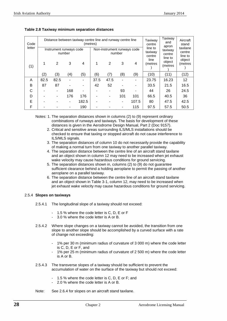
Irish Aviation Authority January 2014
28 Chapter 2 Aerodrome Licensing Manual
Table 2.8 Taxiway minimum separation distances
Code letter
Distance between taxiway centre line and runway centre line (metres)
Taxiway centre line to
taxiway centre
line (metres
)
Taxiway and
apron taxiway centre line to object
(metres)
Aircraft stand
taxilane centre line to object
(metres)
Instrument runways code number
Non-instrument runways code number
(1) 1 2 3 4 1 2 3 4
(2) (3) (4) (5) (6) (7) (8) (9) (10) (11) (12)
A 82.5 82.5 - - 37.5 47.5 - - 23.75 16.23 12
B 87 87 - - 42 52 - - 33.5 21.5 16.5
C - - 168 - - - 93 - 44 26 24.5
D - - 176 176 - - 101 101 66.5 40.5 36
E - - - 182.5 - - - 107.5 80 47.5 42.5
F - - - 190 - - - 115 97.5 57.5 50.5
Notes: 1. The separation distances shown in columns (2) to (9) represent ordinary combinations of runways and taxiways. The basis for development of these distances is given in the Aerodrome Design Manual, Part 2 (Doc 9157).
2. Critical and sensitive areas surrounding ILS/MLS installations should bechecked to ensure that taxiing or stopped aircraft do not cause interference toILS/MLS signals.
3. The separation distances of column 10 do not necessarily provide the capabilityof making a normal turn from one taxiway to another parallel taxiway.
4. The separation distance between the centre line of an aircraft stand taxilaneand an object shown in column 12 may need to be increased when jet exhaustwake velocity may cause hazardous conditions for ground servicing.
5. The separation distances shown in, columns (2) to (9) do not guaranteesufficient clearance behind a holding aeroplane to permit the passing of anotheraeroplane on a parallel taxiway.
6. The separation distance between the centre line of an aircraft stand taxilaneand an object shown in Table 3-1, column 12, may need to be increased whenjet exhaust wake velocity may cause hazardous conditions for ground servicing.
2.5.4 Slopes on taxiways
2.5.4.1 The longitudinal slope of a taxiway should not exceed:
- 1.5 % where the code letter is C, D, E or F - 3.0 % where the code letter is A or B.
2.5.4.2 Where slope changes on a taxiway cannot be avoided, the transition from one slope to another slope should be accomplished by a curved surface with a rate of change not exceeding:
- 1% per 30 m (minimum radius of curvature of 3 000 m) where the code letter is C, D, E or F, and
- 1% per 25 m (minimum radius of curvature of 2 500 m) where the code letter is A or B.
2.5.4.3 The transverse slopes of a taxiway should be sufficient to prevent the accumulation of water on the surface of the taxiway but should not exceed:
- 1.5 % where the code letter is C, D, E or F; and - 2.0 % where the code letter is A or B.
Note: See 2.6.4 for slopes on an aircraft stand taxilane.
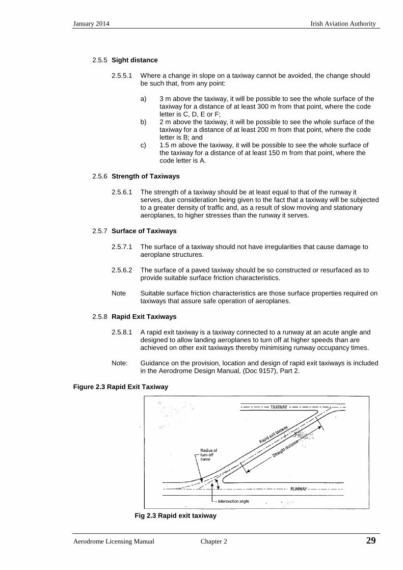
January 2014 Irish Aviation Authority
Aerodrome Licensing Manual Chapter 2 29
2.5.5 Sight distance
2.5.5.1 Where a change in slope on a taxiway cannot be avoided, the change should be such that, from any point:
a) 3 m above the taxiway, it will be possible to see the whole surface of the
taxiway for a distance of at least 300 m from that point, where the code letter is C, D, E or F;
b) 2 m above the taxiway, it will be possible to see the whole surface of the taxiway for a distance of at least 200 m from that point, where the code letter is B; and
c) 1.5 m above the taxiway, it will be possible to see the whole surface of the taxiway for a distance of at least 150 m from that point, where the code letter is A.
2.5.6 Strength of Taxiways
2.5.6.1 The strength of a taxiway should be at least equal to that of the runway it
serves, due consideration being given to the fact that a taxiway will be subjected to a greater density of traffic and, as a result of slow moving and stationary aeroplanes, to higher stresses than the runway it serves.
2.5.7 Surface of Taxiways
2.5.7.1 The surface of a taxiway should not have irregularities that cause damage to
aeroplane structures.
2.5.6.2 The surface of a paved taxiway should be so constructed or resurfaced as to provide suitable surface friction characteristics.
Note Suitable surface friction characteristics are those surface properties required on taxiways that assure safe operation of aeroplanes.
2.5.8 Rapid Exit Taxiways
2.5.8.1 A rapid exit taxiway is a taxiway connected to a runway at an acute angle and designed to allow landing aeroplanes to turn off at higher speeds than are achieved on other exit taxiways thereby minimising runway occupancy times.
Note: Guidance on the provision, location and design of rapid exit taxiways is included
in the Aerodrome Design Manual, (Doc 9157), Part 2.
Figure 2.3 Rapid Exit Taxiway
Fig 2.3 Rapid exit taxiway
Irish Aviation Authority January 2014
30 Chapter 2 Aerodrome Licensing Manual
2.5.8.2 A rapid exit taxiway should be designed with a radius of turn-off of at least:
- 550 m where the code number is 3 or 4; and - 275 m where the code number is 1 or 2.
to enable exit speeds of:
- 50 kt (93 km/h) where the code number is 3 or 4; and - 35 kt (65 km/h) where the code number is 1 or 2.
Note. The locations of rapid exit taxiways along a runway are based on several criteria
described in the Aerodrome Design Manual (Doc 9157), Part 2, in addition to different speed criteria.
2.5.8.3 The radius of the fillet on the inside of the curve at a rapid exit taxiway should
be sufficient to provide a widened taxiway throat in order to provide early recognition of the entrance and turn-off on to the taxiway.
2.5.8.4 A rapid exit taxiway should include a straight distance after the turn-off curve
sufficient for an exiting aircraft to come to a full stop clear of any intersecting taxiway.
2.5.8.5 The intersecting angle of a rapid exit taxiway with the runway should not be
greater than 45 degrees or less than 25 degrees and preferably should be 30 degrees.
2.5.9 Taxiway Shoulders
2.5.9.1 Straight portions of a taxiway where the code letter is C, D, E or F should be provided with shoulders which extend symmetrically on each side of the taxiway so that the overall width of the taxiway and its shoulders on straight portions is not less than: - 60 m where the code letter is F; - 44 m where the code letter is E; - 38 m where the code letter is D; and - 25 m where the code letter is C.
Note: Guidance on characteristics of runway shoulders and on shoulder treatment is
given in the Aerodrome Design Manual, Part 2 (Doc 9157). 2.5.9.2 On taxiway curves and on junctions or intersections where increased pavement
is provided, the shoulder width should be not less than that on the adjacent straight portions of the taxiway.
2.5.9.3 When a taxiway is intended to be used by turbine-engined aeroplanes the
surface of the runway shoulder should be so prepared as to resist erosion and the ingestion of the surface material by aeroplane engines.
2.5.10 Taxiway Strips
2.5.10.1 A taxiway, other than an aircraft stand taxilane, shall be included in a strip.
Note: Guidance on the characteristics of taxiway strips is given in the Aerodrome Design Manual, Part 2 (Doc 9157).
2.5.10.2 A taxiway strip should extend symmetrically on each side of the centre line of
the taxiway throughout the length of the taxiway to at least the distance from the centre line given in Table 2.8, column 11.
January 2014 Irish Aviation Authority
Aerodrome Licensing Manual Chapter 2 31
2.5.10.3 The taxiway strip should provide an area clear of objects which may endanger taxiing aeroplanes.
Note: Consideration will have to be given to the location and design of drains on a
taxiway strip to prevent damage to an aeroplane accidentally running off a taxiway. Suitably designed drain covers may be required.
2.5.10.4 The centre portion of the taxiway strip should provide a graded area to a
distance from the centre line of the taxiway of at least:
- 11 m where the code letter is A; - 12.5 m where the code letter is B or C; - 19 m where the code letter is D; - 22 m where the code letter is E; and - 30 m where the code letter is F.
2.5.10.5 On taxiway curves, junctions and intersections where extra pavement is
provided a corresponding increase should be made in the width of the taxiway strip and graded area.
2.5.10.6 The surface of the strip should be flush at the edge of the taxiway or shoulder if
provided, and the graded portion should not have an upward transverse slope exceeding:
- 2.5 % for taxiway strips where the code letter is C, D, E or F; and - 3.0 % for taxiway strips where the code letter is A or B,
the upward slope being measured with reference to the transverse slope of the adjacent taxiway surface and not the horizontal. The downward transverse slope should not exceed 5 % measured with reference to the horizontal.
2.5.10.7 The transverse slopes on any portion of a taxiway strip beyond that to be
graded should not exceed an upward or downward slope of 5 % as measured in the direction away from the taxiway.
2.5.11 Holding bays, runway-holding positions, intermediate holding positions and road
holding positions
2.5.11.1 Holding bay(s) should be provided when the traffic density is medium or heavy.
2.5.11.2 A runway-holding position or positions shall be established:
a) on the taxiway, at the intersection of a taxiway and a runway; and b) at an intersection of a runway with another runway when the former
runway is part of a standard taxi-route.
2.5.11.3 A runway-holding position shall be established on a taxiway if the location or alignment of the taxiway is such that a taxiing aircraft or vehicle can infringe an obstacle limitation surface or interfere with the operation of radio navigation aids.
2.5.11.4 An intermediate holding position should be established on a taxiway at any point
other than a runway-holding position where it is desirable to define a specific holding limit.
2.5.11.5 A road holding position shall be established at an intersection of a road with a
runway.
2.5.11.6 The distance between a holding bay, runway-holding position established at a taxiway/runway intersection or road holding position and the centre line of a
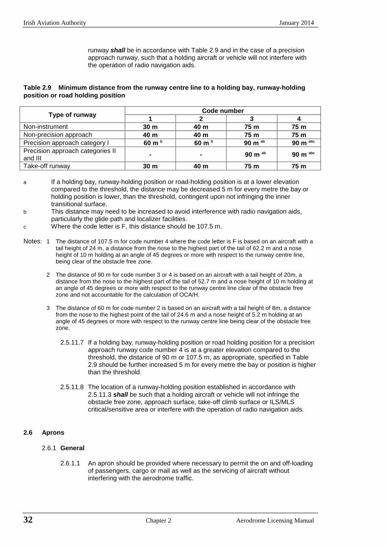
Irish Aviation Authority January 2014
32 Chapter 2 Aerodrome Licensing Manual
runway shall be in accordance with Table 2.9 and in the case of a precision approach runway, such that a holding aircraft or vehicle will not interfere with the operation of radio navigation aids.
Table 2.9 Minimum distance from the runway centre line to a holding bay, runway-holding
position or road holding position
Type of runway Code number
1 2 3 4
Non-instrument 30 m 40 m 75 m 75 m
Non-precision approach 40 m 40 m 75 m 75 m
Precision approach category I 60 m b 60 m b 90 m ab 90 m abc
Precision approach categories II and III
- - 90 m ab 90 m abc
Take-off runway 30 m 40 m 75 m 75 m
a If a holding bay, runway-holding position or road-holding position is at a lower elevation
compared to the threshold, the distance may be decreased 5 m for every metre the bay or holding position is lower, than the threshold, contingent upon not infringing the inner transitional surface.
b This distance may need to be increased to avoid interference with radio navigation aids, particularly the glide path and localizer facilities.
c Where the code letter is F, this distance should be 107.5 m. Notes: 1 The distance of 107.5 m for code number 4 where the code letter is F is based on an aircraft with a
tail height of 24 m, a distance from the nose to the highest part of the tail of 62.2 m and a nose height of 10 m holding at an angle of 45 degrees or more with respect to the runway centre line, being clear of the obstacle free zone.
2 The distance of 90 m for code number 3 or 4 is based on an aircraft with a tail height of 20m, a
distance from the nose to the highest part of the tail of 52.7 m and a nose height of 10 m holding at an angle of 45 degrees or more with respect to the runway centre line clear of the obstacle free zone and not accountable for the calculation of OCA/H.
3 The distance of 60 m for code number 2 is based on an aircraft with a tail height of 8m, a distance
from the nose to the highest point of the tail of 24.6 m and a nose height of 5.2 m holding at an angle of 45 degrees or more with respect to the runway centre line being clear of the obstacle free zone.
2.5.11.7 If a holding bay, runway-holding position or road holding position for a precision
approach runway code number 4 is at a greater elevation compared to the threshold, the distance of 90 m or 107.5 m, as appropriate, specified in Table 2.9 should be further increased 5 m for every metre the bay or position is higher than the threshold.
2.5.11.8 The location of a runway-holding position established in accordance with
2.5.11.3 shall be such that a holding aircraft or vehicle will not infringe the obstacle free zone, approach surface, take-off climb surface or ILS/MLS critical/sensitive area or interfere with the operation of radio navigation aids.
2.6 Aprons
2.6.1 General
2.6.1.1 An apron should be provided where necessary to permit the on and off-loading
of passengers, cargo or mail as well as the servicing of aircraft without interfering with the aerodrome traffic.
January 2014 Irish Aviation Authority
Aerodrome Licensing Manual Chapter 2 33
2.6.1.2 When an aerodrome is used extensively by helicopters that have skid undercarriages and are therefore obliged to hover-taxi between the apron and the operating areas, provision of a discrete helicopter apron is recommended.
2.6.2 Size of aprons
2.6.2.1 The total apron area should be adequate to permit expeditious handling of the
aerodrome traffic for its maximum anticipated density.
2.6.3 Strength of aprons
2.6.3.1 Each part of an apron should be capable of withstanding the traffic of the
aircraft it is intended to serve, due consideration being given to the fact that some portions of the apron will be subjected to a higher density of traffic and, as a result of slow moving or stationary aircraft to higher stresses than a runway.
2.6.4 Slopes on aprons
2.6.4.1 Slopes on an apron, including those on an aircraft stand taxilane, should be
sufficient to prevent the accumulation of water on the surface of the apron but should be kept as level as drainage conditions permit.
2.6.4.2 On an aircraft stand the maximum slope should not exceed 1%.
2.6.5 Clearance distances
2.6.5.1 An aircraft stand should provide the following minimum clearances between an
aircraft using the stand and any adjacent building, aircraft on another stand and other objects.
Code letter Clearance A 3 m B 3 m C 4.5 m D 7.5 m E 7.5 m F 7.5 m
When special circumstances so warrant, these distances may be reduced at a nose-in aircraft stand where the code letter is D, E or F:
a) between the terminal, including any fixed passenger bridge and the nose of
an aircraft; b) over any portion of the stand provided with azimuth guidance by a visual
docking guidance system.
Note: On aprons, consideration also has to be given to the provision of service roads and to manoeuvring and storage area for ground equipment. (See the Aerodrome Design Manual, Part 2 (Doc 9157) for guidance on storage of ground equipment).
2.7 Isolated Aircraft Parking Position
2.7.1 General
2.7.1.1 An isolated aircraft parking position shall be designated, or the aerodrome control tower shall be advised of an area or areas suitable for the parking of an aircraft which is known or believed to be the subject of unlawful interference, or which for other reasons needs isolation from normal aerodrome activities.
Irish Aviation Authority January 2014
34 Chapter 2 Aerodrome Licensing Manual
2.7.1.2 The isolated aircraft parking position should be located at the maximum
distance practicable and in any case not less than 100 m from other parking positions, buildings or public areas etc. Care should be taken to ensure that the position is not located over underground utilities such as gas and aviation fuel and, to the extent feasible electrical or communication cables.
2.8 De-Icing/Anti-Icing Facilities
2.8.1 General
2.8.1.1 Aeroplane de-icing/anti-icing facilities should be provided at an aerodrome where icing conditions are expected to occur.
2.8.1.2 De-icing/anti-icing facilities should be provided either at aircraft stands or at
specified remote areas along the taxiway leading to the runway meant for take-off, provided that adequate drainage arrangements for the collection and safe disposal of excess de-icing/anti-icing fluids are available to prevent ground water contamination. The effect of volume of traffic and departure flow rates should also be considered.
Notes: 1 One of the primary factors influencing the location of the facility is to ensure
that the holdover time of the anti-icing treatment is still in effect at the end of the taxiing and when take-off clearance of the treated aeroplane is given.
2 Remote facilities compensate for changing weather conditions when icing conditions or blowing snow are expected to occur along the taxi route taken by the aeroplane to the runway meant for take-off.
2.8.1.3 The remote de-icing/anti-icing facility should be located:
a) to be clear of the obstacle limitation surfaces specified in Chapter 5, not
cause interference to the radio navigation aids and should be clearly visible from the air traffic control tower for clearing the treated aeroplane; and
b) so as to provide for an expeditious traffic flow, perhaps with a bypass
configuration and not require unusual taxiing manoeuvre into and out of the pads.
Notes: The jet blast effects caused by a moving aeroplane on other aeroplanes
receiving the anti-icing treatment or taxiing behind will have to be taken into account to prevent degradation of the treatment.
2.8.2 Size and number 2.8.2.1 The size of a de-icing/anti-icing pad should be equal to the parking area
required by the most demanding aeroplane with at least 3.8 m clear paved area all around the aeroplane for the movement of de-icing/anti-icing vehicles.
Note: An aeroplane de-icing/anti-icing pad consists of:
a) an inner area for the parking of an aeroplane to be treated; and b) an outer area for movement of two or more mobile de-icing/anti-icing
equipment.
2.8.2.2 The number of de-icing/anti-icing pads required should be determined based on the meteorological conditions, the type of aeroplanes to be treated, the method of application of de-icing/anti icing fluid, the type and capacity of the dispensing equipment, and the departure flow rates (See the Aerodrome Design Manual, Part 2 (Doc 9157)).
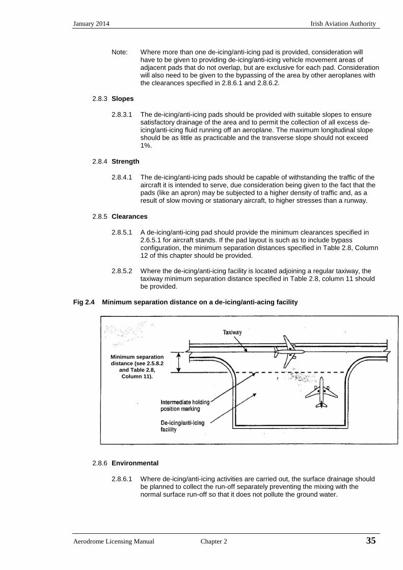
January 2014 Irish Aviation Authority
Aerodrome Licensing Manual Chapter 2 35
Note: Where more than one de-icing/anti-icing pad is provided, consideration will have to be given to providing de-icing/anti-icing vehicle movement areas of adjacent pads that do not overlap, but are exclusive for each pad. Consideration will also need to be given to the bypassing of the area by other aeroplanes with the clearances specified in 2.8.6.1 and 2.8.6.2.
2.8.3 Slopes
2.8.3.1 The de-icing/anti-icing pads should be provided with suitable slopes to ensure
satisfactory drainage of the area and to permit the collection of all excess de-icing/anti-icing fluid running off an aeroplane. The maximum longitudinal slope should be as little as practicable and the transverse slope should not exceed 1%.
2.8.4 Strength
2.8.4.1 The de-icing/anti-icing pads should be capable of withstanding the traffic of the
aircraft it is intended to serve, due consideration being given to the fact that the pads (like an apron) may be subjected to a higher density of traffic and, as a result of slow moving or stationary aircraft, to higher stresses than a runway.
2.8.5 Clearances
2.8.5.1 A de-icing/anti-icing pad should provide the minimum clearances specified in
2.6.5.1 for aircraft stands. If the pad layout is such as to include bypass configuration, the minimum separation distances specified in Table 2.8, Column 12 of this chapter should be provided.
2.8.5.2 Where the de-icing/anti-icing facility is located adjoining a regular taxiway, the
taxiway minimum separation distance specified in Table 2.8, column 11 should be provided.
Fig 2.4 Minimum separation distance on a de-icing/anti-acing facility
2.8.6 Environmental
2.8.6.1 Where de-icing/anti-icing activities are carried out, the surface drainage should
be planned to collect the run-off separately preventing the mixing with the normal surface run-off so that it does not pollute the ground water.
Minimum separation
distance (see 2.5.8.2
and Table 2.8,
Column 11).
Irish Aviation Authority January 2014
36 Chapter 2 Aerodrome Licensing Manual
Note: The excess de-icing/anti-icing fluid running off an aeroplane poses the risk of contamination of ground water in addition to affecting the pavement friction characteristics.
2.8.7 Airport Design
2.8.7.1 Architectural and infrastructure-related requirements for the optimum
implementation of international civil aviation security measures shall be integrated into the design and construction of new facilities and alterations to existing facilities at an aerodrome.
Note: Guidance on all aspects of the planning of aerodromes including security
considerations is contained in the Airport Planning Manual, Part 1 (Doc 9184).
2.8.7.2 The design of aerodromes should take into account, where appropriate, land-use and environmental control measures.
Note: Guidance on all aspects of the planning of aerodromes including security
considerations is contained in the Airport Planning Manual, Part 2 (Doc 9184).
January 2014 Irish Aviation Authority
Aerodrome Licensing Manual Chapter 2 37
APPENDIX 2A Movement Area Bearing Strength
2A1 Introduction
2A1.1 Paving forming part of the movement area needs to be of sufficient strength to allow aircraft
to operate without risk of damage either to the pavement or to the aircraft. Pavements subject to overload conditions will deteriorate at an increasing rate depending upon the degree of overload. To control this it is necessary to classify both pavement and aircraft under a system whereby the loading capacity of the pavement and the loads imposed by the aircraft can be compared.
2A2 Bearing Strength of Pavements
2A2.1 The bearing strength of a pavement shall be determined. 2A2.2 The bearing strength of a pavement intended for aircraft of apron mass greater than 5,700
kg shall be made available using the aircraft classification number - pavement classification number (ACN - PCN) method by reporting all of the following information:
- the pavement classification number (PCN); - pavement type for ACN - PCN determination; - sub-grade strength category; - maximum allowable tyre pressure category or maximum allowable tyre pressure
value; and - evaluation method.
Note: If necessary the PCN may be published to an accuracy of one-tenth of a whole number. 2A2.3 The pavement classification number (PCN) reported shall indicate that an aircraft with an
Aircraft Classification Number (ACN) equal to or less than the reported PCN can operate on the pavement subject to any limitation on the tyre pressure, or aircraft all-up mass for specified type(s).
Note: Different PCN’s may be reported if the strength of the pavement is subject to significant
seasonal variation. 2A2.4 The ACN of an aircraft shall be determined in accordance with the standard procedures
associated with the ACN - PCN method. Note: The standard procedures for determining the ACN of an aircraft are given in the Aircraft
Design Manual, Part 3. For convenience several aircraft types currently in use have been evaluated for rigid and flexible pavements founded on the four sub-grade categories and the results tabulated in that manual.
2A2.5 For the purposes of determining the ACN, the behaviour of a pavement shall be classified
as equivalent to a rigid or flexible construction. 2A2.6 Information on pavement type for ACN - PCN determination, sub-grade strength category,
maximum allowable tyre pressure category and evaluation method shall be reported using the following codes:
a) pavement type for ACN - PCN determination
Code rigid pavement R flexible pavement F
Note: If the actual construction is composite or non-standard, include a note to that effect (See
example 2) b) sub-grade strength category
Irish Aviation Authority January 2014
38 Chapter 2 Aerodrome Licensing Manual
Code high strength: characterised by K= A 150 MN/m3 and representing all K values above 120 MN/m3 for rigid pavements, and by CBR = 15 and representing all CBR values above 13 for flexible pavements.
medium strength: characterised by K= B
80 MN/m3 and representing a range in K of 60 to 120 MN/m3 for rigid pavements, and by CBR = 10 and representing a range in CBR of 8 to 13 for flexible pavements.
low strength: characterised by K = C 40 MN/m3
and representing a range in K of
25 to 60 MN/m3 for rigid pavements, and by CBR = 6 and representing a range in CBR of 4 to 8 for flexible pavements
ultra low strength: characterized by K = D 20 MN/m3 and representing all K values below 25 MN/m3 for rigid pavements, and by CBR = 3 and representing all CBR values below 4 for flexible pavements.
c) maximum allowable tyre pressure category
Code
Unlimited: no pressure limit W
High: pressure limited to 1.50 MPa X
Medium: pressure limited to 1.00 MPa Y
Low: pressure limited to 0.50 MPa Z
Note See Note 5 to 7.3.1 where the pavement is used by aircraft with tire pressures in the upper categories
d) evaluation method
Code
Technical evaluation: representing a specific T study of the pavement characteristics and application of pavement behaviour technology.
Using aircraft experience: representing a U knowledge of the specific type and mass of aircraft satisfactorily being supported under regular use.
The following examples illustrate how pavement strength data are reported under the ACN - PCN method.
1. If the bearing strength of a rigid pavement, resting on a medium strength sub-grade, hasbeen assessed by technical evaluation to be PCN 80 and there is no tyre pressurelimitation, then the reported information would be:
PCN 80 / R / B / W / T
2. If the bearing strength of a composite pavement, behaving like a flexible pavement andresting on a high strength sub-grade has been assessed by using aircraft experience tobe PCN 50 and the maximum tyre pressure allowable is 1.00 MPa, then the reportedinformation would be:
PCN 50 / F / A / Y / U Note - Composite construction
January 2014 Irish Aviation Authority
Aerodrome Licensing Manual Chapter 2 39
3. If the bearing strength of a flexible pavement, resting on a medium strength sub-grade
has been assessed by technical evaluation to be PCN 40 and the maximum allowable tyre pressure is 0.80 MPa then the reported information would be:
PCN 40 / F / B / 0.80 MPa / T
4. If a pavement is subject to a B747-400 all up mass limitation of 390,000 kg then the reported information would include the following note:
Note: The reported PCN is subject to a B747-400 all up mass limitation of 390,000 kg.
2A2.7 The bearing strength of a pavement intended for aircraft of apron (ramp) mass equal to or
less than 5,700 kg shall be made available by reporting the following information:
a) maximum allowable aircraft mass; and
b) maximum allowable tyre pressure.
Example: 4,000 kg / 0.50 MPa.
2A2.8 Criteria should be established to regulate the use of a pavement by an aircraft with an ACN
higher than the PCN reported for that pavement in accordance with 2A2.2 and 2A2.3.
2A.3 Overload Operations
2A3.1 Overloading of pavements can result either from loads too large or from a substantially
increased application rate or both. With the exception of massive overloading, pavements in their structural behaviour are not subject to a particular limiting load above which, they suddenly and catastrophically fail. Behaviour is such that a pavement can sustain a definable load for an expected number of repetitions during its design life. As a result, occasional minor overloading is acceptable, when expedient, with only limited loss in pavement life expectancy and relatively small acceleration of pavement deterioration. For those operations in which magnitude of overload and/or the frequency of use do not justify a detailed analysis, the following criteria are suggested:
a) for flexible pavements, occasional movements by aircraft with ACN not exceeding 10 per cent above the reported PCN should not adversely affect the pavement;
b) for rigid or composite pavements, in which a rigid pavement layer provides a primary element of the structure, occasional movements by aircraft with ACN not exceeding 5 per cent above the reported PCN should not adversely affect the pavement;
c) if the pavement structure is unknown, the 5 per cent limitation should apply; and
d) the annual number of overload movements should not exceed approximately 5 per cent of the total annual aircraft movements.
2A3.2 Such overload movements should not normally be permitted on pavements exhibiting signs
of distress or failure. Furthermore, overloading should be avoided during any periods of thaw following frost penetration, or when the strength of the pavement or its subgrade could be weakened by water. Where overload operations are conducted, the appropriate authority should review the relevant pavement condition regularly, and should also review the criteria for overloads can cause severe shortening of pavement life or require major rehabilitation of pavement.
2A3.3 Using the guidance material on overload operations presented in the Aerodrome Design
Manual, Part 3 (Doc 9157) individual aerodrome operators in Ireland may decide on their own criteria for permitting overload operations as long as pavements remain safe for use by aircraft.

Irish Aviation Authority January 2014
40 Chapter 2 Aerodrome Licensing Manual
INTENTIONALY BLANK
January 2014 Irish Aviation Authority
Aerodrome Licensing Manual Chapter 2 41
APPENDIX 2B Declared Distances
2B1 Calculation of Declared Distances
2B1.1 The declared distances to be calculated for each runway direction comprise; the take-off run
available (TORA), take-off distance available (TODA), accelerate-stop distance available (ASDA), and landing distance available (LDA).
2B1.2 Where a runway is not provided with a stopway or clearway and the threshold is located at
the extremity of the runway, the four declared distances should normally be equal to the length of the runway as shown in Figure 2B.1 (A).
2B1.3 Where a runway is provided with a clearway (CWY), then the TODA will include the length of
the clearway, as shown in Figure 2B.1 (B). 2B1.4 Where a runway is provided with a stopway (SWY), then the ASDA will include the length of
the stopway, as shown in Figure 2B.1 (C). 2B1.5 Where a runway has a displaced threshold, then the LDA will be reduced by the distance the
threshold is displaced as shown in Figure 2B.1 (D). A displaced threshold affects only the LDA for approaches made to that threshold. All declared distances for operations in the reciprocal direction are unaffected.
2B1.6 Figures 2B.1 (B) through (D) illustrate a runway provided with a clearway or a stopway or
having a displaced threshold. Where more than one of these features exists, then more than one of the declared distances will be modified - but the modification will follow the same principle illustrated. An example showing a situation where all these features exist is shown in Figure 2B.1 (E).
2B1.7 A suggested format for providing information on declared distances is given in Figure 2B.1
(F). If a runway direction cannot be used for take-off or landing or both because it is operationally forbidden, then this should be declared and the words “not usable” or the abbreviation “NU” entered.
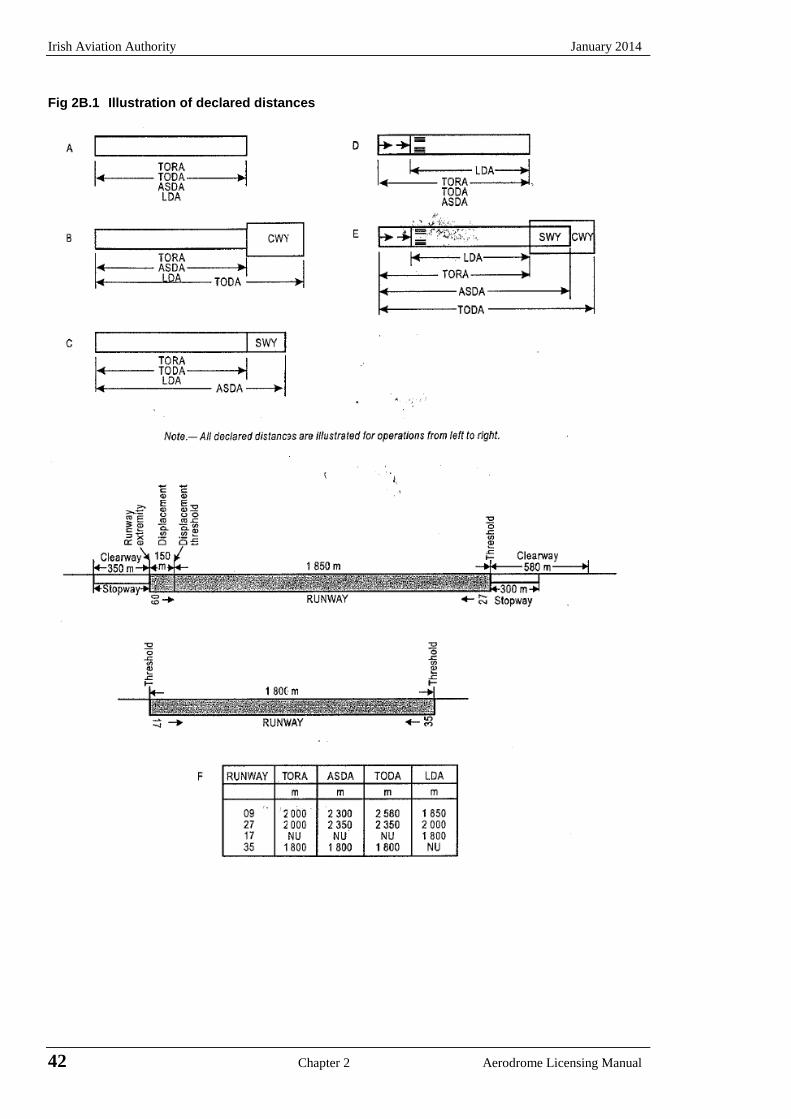
Irish Aviation Authority January 2014
42 Chapter 2 Aerodrome Licensing Manual
Fig 2B.1 Illustration of declared distances
January 2014 Irish Aviation Authority
CHAPTER 3 AERODROME GROUND LIGHTING 3.1 Introduction
3.1.1 Aerodrome ground lighting provides the pilot with location, orientation and alignment information in adverse visibility conditions and at night. The type of lighting is specified according to the runway approach category and take-off minima. Where the prescribed scale cannot be provided for an instrument runway there may be a consequential penalty on operational minima.
3.2 General Requirements
3.2.1 Light fixtures and supporting structures
3.2.1.1 Elevated approach lights and their supporting structures shall be frangible except that, in that portion of the approach lighting system beyond 300 m from the threshold:
a) where the height of the supporting structure exceeds 12 m, the frangibility
requirement shall apply to the top 12 m only; and b) where a supporting structure is surrounded by non-frangible objects, only
that part of the structure that extends above the surrounding objects shall be frangible.
3.2.1.2 When an approach light fixture or supporting structure is not in itself sufficiently
conspicuous, it shall be suitably marked.
3.2.1.3 Elevated runway, stopway, and taxiway lights shall be frangible. Their height shall be sufficiently low to preserve clearance for propellers and for the engine pods of jet aircraft.
3.2.1.4 Light fixtures inset in the surface of runways, stopways, taxiways and aprons
shall be so designed and fitted as to withstand being run over by the wheels of an aircraft without damage to the aircraft or the lights themselves.
3.2.1.5 The temperature produced by conduction or radiation at the interface between
an installed inset light and an aircraft tyre should not exceed 160 degrees C during a 10 minute period of exposure.
Note: Guidance on measuring the temperature of inset lights is given in the
Aerodrome Design Manual, Part 4 (Doc 9157).
3.2.2 Light intensity and control
Note: In dusk or poor visibility conditions by day, lighting can be more effective than marking. For lights to be effective in such conditions or in poor visibility at night, they must be of adequate intensity. To obtain the required intensity it will usually be necessary to make the light directional, in which case the arcs over which the light shows will have to be adequate and so oriented as to meet the operational requirements. The runway lighting system will have to be considered as a whole to ensure that the relative light intensities are suitably matched to the same end. (See Annex 14, Attachment A, Section 14 and the Aerodrome Design Manual, Part 4 (Doc 9157)).
Aerodrome Licensing Manual Chapter 3 43
Irish Aviation Authority January 2014
3.2.2.1 The intensity of runway lighting shall be adequate for the minimum conditions of visibility and ambient light in which use of the runway is intended and compatible with that of the nearest section of the approach lighting system when provided.
Note: While the lights of the approach lighting system may be of higher intensity than the runway
lighting, it is good practice to avoid abrupt changes in intensity as these could give a pilot a false impression that the visibility is changing during approach.
3.2.2.2 Where a high intensity lighting system is provided, a suitable intensity control shall be
incorporated to allow for adjustment of the light intensity to meet the prevailing conditions. Separate intensity controls or other suitable methods shall be provided to ensure that the following systems when installed can be operated at compatible intensities: − approach lighting system − runway edge lights − runway threshold lights − runway end lights − runway centre line lights − runway touch down zone lights − taxiway centre line lights
3.2.2.3 The intensity and beam spreads of lights are presented in Isocandela diagrams that form
Appendix 2 of Annex 14. The full list of diagrams, with the associated Appendix 2 figure references, main beam minimum average intensities (unless otherwise indicated) and type of light are shown in Table 3.1:
3.2.2.4 On the perimeter of and within the ellipse defining the main beam in Appendix 2, Figures A2-
1 to A2-10, the maximum light intensity value shall not be greater than three times the minimum light intensity value measured in accordance with Appendix 2, collective notes for Figures A2-1 to A2-11, Note 2.
3.2.2.5 On the perimeter of and within the rectangle defining the main beam in Appendix 2, Figures
A2-12 to A2-20, the maximum light intensity value shall not be greater than three times the minimum light intensity value measured in accordance with Appendix 2, collective notes for Figures A2-12 to A2-21, Note2.
3.2.2.6 Light intensity settings for different RVR and covering day conditions, night conditions and
dawn and dusk (twilight) conditions are presented in the Aerodrome Design Manual, Part 4. The intensities apply to the main beam dimensions specified in Annex 14, Appendix 2. Although the requirement for high intensities normally occurs during the day it is acceptable practice when conditions permit to use a power setting lower than the maximum as the lamp life is greatly lengthened when operated at a reduced intensity.
3.2.2.7 Typical light intensity control stages and light intensity settings, for different RVR during day,
night and twilight conditions, developed for use in Ireland are tabulated in Table 3.2. However the final choice rests with the pilot and the values may require adjustment as a result of local operational experience.
3.2.3 Emergency lighting
3.2.3.1 At an aerodrome provided with runway lighting and without a secondary power supply,
sufficient emergency lights should be conveniently available for installation on at least the primary runway in the event of failure of the normal lighting system.
Note: Emergency lighting may also be useful to mark obstacles or delineate taxiways and apron
areas.
3.2.3.2 When installed on a runway the emergency lights should, as a minimum, conform to the configuration required for a non-instrument runway.
44 Chapter 3 Aerodrome Licensing Manual
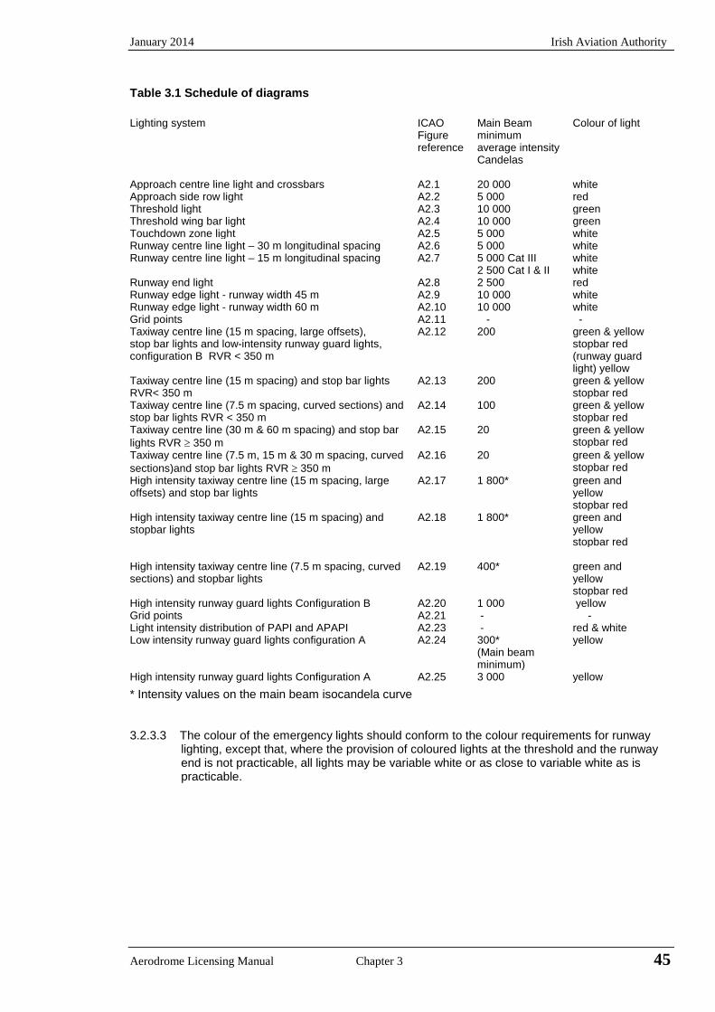
January 2014 Irish Aviation Authority
Table 3.1 Schedule of diagrams Lighting system ICAO
Figure reference
Main Beam minimum average intensity Candelas
Colour of light
Approach centre line light and crossbars A2.1 20 000 white Approach side row light A2.2 5 000 red Threshold light A2.3 10 000 green Threshold wing bar light A2.4 10 000 green Touchdown zone light A2.5 5 000 white Runway centre line light – 30 m longitudinal spacing A2.6 5 000 white Runway centre line light – 15 m longitudinal spacing A2.7 5 000 Cat III
2 500 Cat I & II white white
Runway end light A2.8 2 500 red Runway edge light - runway width 45 m A2.9 10 000 white Runway edge light - runway width 60 m A2.10 10 000 white Grid points A2.11 - - Taxiway centre line (15 m spacing, large offsets), stop bar lights and low-intensity runway guard lights, configuration B RVR < 350 m
A2.12 200 green & yellow stopbar red (runway guard light) yellow
Taxiway centre line (15 m spacing) and stop bar lights RVR< 350 m
A2.13 200 green & yellow stopbar red
Taxiway centre line (7.5 m spacing, curved sections) and stop bar lights RVR < 350 m
A2.14 100 green & yellow stopbar red
Taxiway centre line (30 m & 60 m spacing) and stop bar lights RVR ≥ 350 m
A2.15 20 green & yellow stopbar red
Taxiway centre line (7.5 m, 15 m & 30 m spacing, curved sections)and stop bar lights RVR ≥ 350 m
A2.16 20 green & yellow stopbar red
High intensity taxiway centre line (15 m spacing, large offsets) and stop bar lights
A2.17 1 800* green and yellow stopbar red
High intensity taxiway centre line (15 m spacing) and stopbar lights
A2.18 1 800* green and yellow stopbar red
High intensity taxiway centre line (7.5 m spacing, curved sections) and stopbar lights
A2.19 400* green and yellow stopbar red
High intensity runway guard lights Configuration B A2.20 1 000 yellow Grid points A2.21 - - Light intensity distribution of PAPI and APAPI A2.23 - red & white Low intensity runway guard lights configuration A A2.24 300*
(Main beam minimum)
yellow
High intensity runway guard lights Configuration A A2.25 3 000 yellow
* Intensity values on the main beam isocandela curve
3.2.3.3 The colour of the emergency lights should conform to the colour requirements for runway lighting, except that, where the provision of coloured lights at the threshold and the runway end is not practicable, all lights may be variable white or as close to variable white as is practicable.
Aerodrome Licensing Manual Chapter 3 45
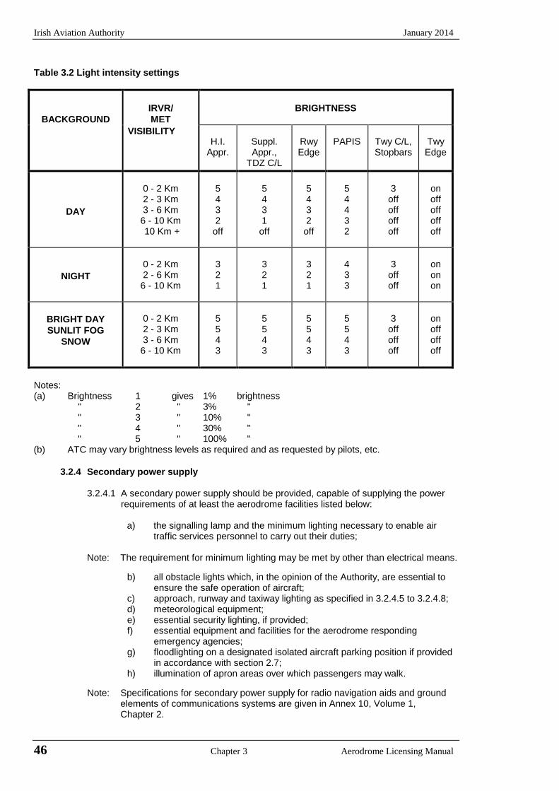
Irish Aviation Authority January 2014
Table 3.2 Light intensity settings
BACKGROUND IRVR/ MET
BRIGHTNESS
VISIBILITY H.I.
Appr. Suppl. Appr.,
TDZ C/L
Rwy Edge
PAPIS Twy C/L, Stopbars
Twy Edge
DAY
0 - 2 Km 2 - 3 Km 3 - 6 Km 6 - 10 Km 10 Km +
5432
off
5431
off
5432
off
54432
3 off off off off
on off off off off
NIGHT 0 - 2 Km 2 - 6 Km 6 - 10 Km
321
321
321
433
3 off off
on on on
BRIGHT DAY SUNLIT FOG
SNOW
0 - 2 Km 2 - 3 Km 3 - 6 Km 6 - 10 Km
5543
5543
5543
5543
3 off off off
on off off off
Notes: (a) Brightness 1 gives 1% brightness
" 2 " 3% " " 3 " 10% " " 4 " 30% " " 5 " 100% "
(b) ATC may vary brightness levels as required and as requested by pilots, etc.
3.2.4 Secondary power supply
3.2.4.1 A secondary power supply should be provided, capable of supplying the power requirements of at least the aerodrome facilities listed below:
a) the signalling lamp and the minimum lighting necessary to enable airtraffic services personnel to carry out their duties;
Note: The requirement for minimum lighting may be met by other than electrical means.
b) all obstacle lights which, in the opinion of the Authority, are essential toensure the safe operation of aircraft;
c) approach, runway and taxiway lighting as specified in 3.2.4.5 to 3.2.4.8;d) meteorological equipment;e) essential security lighting, if provided;f) essential equipment and facilities for the aerodrome responding
emergency agencies;g) floodlighting on a designated isolated aircraft parking position if provided
in accordance with section 2.7;h) illumination of apron areas over which passengers may walk.
Note: Specifications for secondary power supply for radio navigation aids and ground elements of communications systems are given in Annex 10, Volume 1,Chapter 2.
46 Chapter 3 Aerodrome Licensing Manual
January 2014 Irish Aviation Authority
3.2.4.2 Electric power supply connections to those facilities for which secondary power is required should be so arranged that the facilities are automatically connected to the secondary power supply on failure of the primary source of power.
3.2.4.3 The time interval between failure of the primary source of power and the complete restoration of the services to the facilities listed in 3.2.4.1 should be as short as practicable except that for visual aids associated with non-precision, precision approach or take-off runways the requirements of Table 3.3 for maximum switch-over times should apply.
Notes: 1 In certain cases, less than thirty seconds has been found to be attainable. 2 Switch-over time (light) is the time required for the actual intensity of light measured in a given direction to fall from 50% and recover to 50% during a power supply change-over, when the light is being operated at intensities of 25% or above.
3.2.4.4 Requirements for a secondary power supply should be met by either of the following:
a) independent public power, which is a source of power supplying the aerodrome servicefrom a substation other than the normal substation through a transmission line followinga route different from the normal power supply route and such that the possibility of asimultaneous failure of the normal and independent public power supplies is extremelyremote; or
b) standby power unit(s), which are engine generators, batteries etc., from which electricpower can be obtained.
Notes: Guidance on secondary power supply is given in the Aerodrome Design Manual, Part 5 (Doc 9157).
3.2.4.5 For a precision approach runway, a secondary power supply capable of meeting the requirements of Table 3-3 for the appropriate category of precision approach runway shall be provided. Electric power supply connections to those facilities for which secondary power is required shall be so arranged that the facilities are automatically connected to the secondary power supply on failure of the primary source of power.
3.2.4.6 At an aerodrome where the primary runway is an non-instrument runway, a secondary power supply capable of meeting the requirements of 3.2.4.3 should be provided, except that a secondary power supply for visual aids need not be provided when an emergency lighting system in accordance with the specification of 3.2.3 is provided and capable of being deployed in 15 minutes.
3.2.4.7 At an aerodrome where the primary runway is a non precision approach runway, a secondary power supply capable of meeting the requirements of Table 3.3 should be provided except that a secondary power supply for visual aids need not be provided for more than one non-precision runway.
3.2.4.8 For a runway meant for take-off in RVR conditions less than a value of 800 m, a secondary power supply capable of meeting the relevant requirements of Table 3.3 shall be provided.
Aerodrome Licensing Manual Chapter 3 47
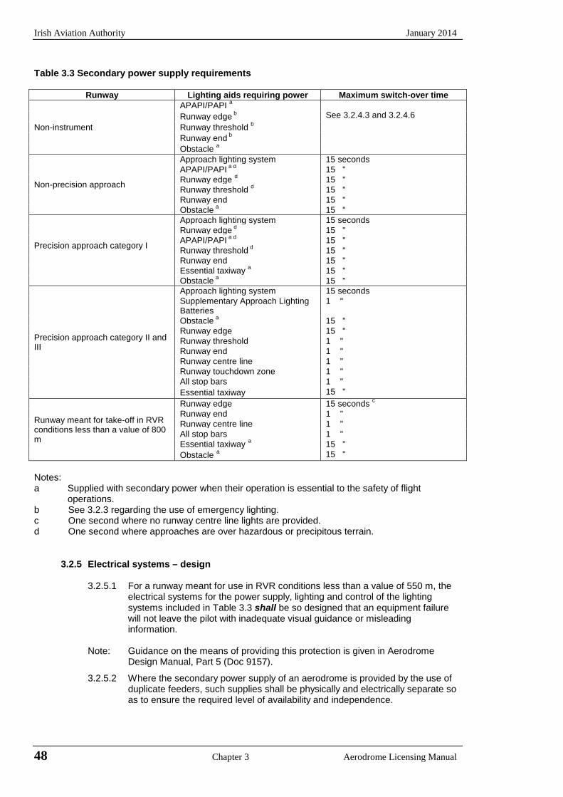
Irish Aviation Authority January 2014
Table 3.3 Secondary power supply requirements
Runway Lighting aids requiring power Maximum switch-over time
Non-instrument
APAPI/PAPI a
See 3.2.4.3 and 3.2.4.6 Runway edge b
Runway threshold b Runway end b Obstacle a
Non-precision approach
Approach lighting system 15 seconds APAPI/PAPI a d 15 " Runway edge d 15 " Runway threshold d 15 " Runway end 15 " Obstacle a 15 "
Precision approach category I
Approach lighting system 15 seconds Runway edge d 15 " APAPI/PAPI a d 15 " Runway threshold d 15 " Runway end 15 " Essential taxiway a 15 " Obstacle a 15 "
Precision approach category II and III
Approach lighting system 15 seconds Supplementary Approach Lighting Batteries
1 "
Obstacle a 15 " Runway edge 15 " Runway threshold 1 " Runway end 1 " Runway centre line 1 " Runway touchdown zone 1 " All stop bars 1 " Essential taxiway 15 "
Runway meant for take-off in RVR conditions less than a value of 800 m
Runway edge 15 seconds c Runway end 1 " Runway centre line 1 " All stop bars 1 " Essential taxiway a 15 " Obstacle a 15 "
Notes: a Supplied with secondary power when their operation is essential to the safety of flight
operations. b See 3.2.3 regarding the use of emergency lighting. c One second where no runway centre line lights are provided. d One second where approaches are over hazardous or precipitous terrain.
3.2.5 Electrical systems – design
3.2.5.1 For a runway meant for use in RVR conditions less than a value of 550 m, the electrical systems for the power supply, lighting and control of the lighting systems included in Table 3.3 shall be so designed that an equipment failure will not leave the pilot with inadequate visual guidance or misleading information.
Note: Guidance on the means of providing this protection is given in Aerodrome
Design Manual, Part 5 (Doc 9157).
3.2.5.2 Where the secondary power supply of an aerodrome is provided by the use of duplicate feeders, such supplies shall be physically and electrically separate so as to ensure the required level of availability and independence.
48 Chapter 3 Aerodrome Licensing Manual

January 2014 Irish Aviation Authority
3.2.5.3 Where a runway forming part of a standard taxi-route is provided with runway lighting and taxiway lighting, the lighting systems shall be interlocked to preclude the possibility of simultaneous operation of both forms of lighting.
Note: Guidance on means of complying with the electrical system requirements are given in the
Aerodrome Design Manual, Part 5 (Doc 9157).
3.2.6 Electrical systems - monitoring 3.2.6.1 A system of monitoring should be employed to indicate the operational status of the lighting
systems. 3.2.6.2 Where lighting systems are used for aircraft control purposes, such systems shall be
monitored automatically so as to provide an indication of any fault which may affect the control functions. This information shall be automatically relayed to the air traffic service unit.
3.2.6.3 For a runway meant for use in RVR conditions less than a value of 550 m, the lighting
systems detailed in Table 3.3 should be monitored so as to provide an immediate indication when the serviceability level of any element falls below the minimum serviceability level specified in 3.2.7.7 to 3.2.7.11 as appropriate. This information should be immediately relayed to the maintenance crew.
3.2.6.4 Where a change in the operational status of lights has occurred, an indication should be provided within two seconds for a stop bar at a runway-holding position and within five seconds for all other types of visual aids.
3.2.6.5 For a runway meant for use in RVR conditions less than a value of 550 m, the lighting systems detailed in Table 3.3 should be monitored automatically to provide an indication when the serviceability level of any element falls below the minimum level specified by the Authority below which operations should not continue. This information should be automatically relayed to the air traffic services unit and displayed in a prominent position.
Unless otherwise agreed with the Authority taking into account the particular features of the
aerodrome concerned, the serviceability level specified in 3.2.7.7 to 3.2.7.11 and associated qualifications should be regarded as the minimum for the operation intended.
3.2.6.6 During low visibility procedures construction or maintenance activities in the proximity of
aerodrome electrical systems should be restricted.
Note: Guidance on the design and control of aerodrome electrical and lighting systems, the air traffic control interface and the monitoring of visual aids is included in the Aerodrome Design Manual, Part 5 (Doc 9157).
3.2.7 Electrical systems – maintenance
Notes 1 These specifications are intended to define the maintenance performance level objectives.
They are not intended to define whether the lighting system is operationally out of service. 2 The energy savings of light emitting diodes (LEDs) are due in large part to the fact that
they do not produce the infra-red heat signature of incandescent lamps. Aerodrome operators who have come to expect the melting of ice and snow by this heat signature may wish to evaluate whether or not a modified maintenance schedule is required during such conditions, or evaluate the possible operational value of installing LED fixtures with heating elements.
3 Enhanced vision systems (EVS) technology relies on the infra-red heat signature provided
by incandescent lighting. Annex 15 protocols provide an appropriate means of notifying aerodrome users of EVS when lighting systems are converted to LED.
Aerodrome Licensing Manual Chapter 3 49
Irish Aviation Authority January 2014
3.2.7.1 A light shall be deemed to be unserviceable when the main beam average intensity is less than 50% of the value specified in the appropriate figure of Annex 14, Appendix 2. For light units where the designed main beam average intensity is above the value shown in Appendix 2 the 50% value shall be related to that design value.
3.2.7.2 A system of preventive maintenance of visual aids shall be employed to ensure lighting and
marking system reliability.
Note: Guidance on preventive maintenance of visual aids is given in the Aerodrome Services Manual, Part 9 (Doc 9157).
3.2.7.3 The system of preventive maintenance employed for a precision approach runway category II or III should include at least the following checks:
a) visual inspection and in-field measurement of the intensity, beam spread
and orientation of lights included in the approach and runway lighting system;
b) control and measurement of the electrical characteristics of each circuitry included in the approach and runway lighting systems; and
c) control of the correct functioning of light intensity settings used by air traffic control.
3.2.7.4 In-field measurement of intensity, beam spread and orientation of lights included in
approach and runway lighting systems for a precision approach runway category II or III should be undertaken by measuring all lights, as far as practicable, to ensure conformance with the applicable specifications of Appendix 2.
3.2.7.5 Measurement of intensity, beam spread and orientation of lights included in
approach and runway lighting systems for a precision approach runway category II or III should be undertaken using a mobile measuring unit of sufficient accuracy to analyse the characteristics of the individual lights.
3.2.7.6 The frequency of measurement of lights for a precision approach runway category II
or III should be based on traffic density, the local pollution level, the reliability of the installed lighting equipment and the continuous assessment of the results of in-field measurements but in any event should not be less than twice a year for in-pavement lights and not less than once a year for other lights.
3.2.7.7 The system of preventive maintenance employed for a precision approach runway
category II or III shall have as its objective that, during any period of category II or III operations, all approach and runway lights are serviceable, and that in any event at least:
a) 95% of the lights are serviceable in each of the following particular significant
elements:
1) precision approach category II and III lighting system, the inner 450m; 2) runway centre line lights; 3) runway threshold lights; and 4) runway edge lights;
b) 90% of the lights are serviceable in the touchdown zone lights;
c) 85% of the lights are serviceable in the approach lighting system beyond
450m; and
d) 75% of the lights are serviceable in the runway end lights.
In order to provide continuity of guidance, the allowable percentage of unserviceable lights shall not be permitted in such a way as to alter the basic pattern of the lighting system. Additionally, an unserviceable light shall not be permitted adjacent to another
50 Chapter 3 Aerodrome Licensing Manual
January 2014 Irish Aviation Authority
unserviceable light, except in a barrette or crossbar where two adjacent unserviceable lights may be permitted.
Note: With respect to barrettes, crossbars and runway edge lights, lights are considered to be
adjacent if located consecutively and: - laterally: in the same barrette or crossbar; or - longitudinally: in the same row of edge lights or barrettes.
3.2.7.8 The system of preventive maintenance employed for a stop bar provided at a runway-
holding position used in conjunction with a runway intended for operations in RVR conditions less than a value of 350 m shall have the following objectives:
a) no more than two lights will remain unserviceable; and b) two adjacent lights will not remain unserviceable unless the light spacing is
significantly less than that specified.
3.2.7.9 The system of preventative maintenance employed for a taxiway intended for use in RVR conditions less than a value of 350 m shall have as its objective that no two adjacent taxiway centre line lights be unserviceable.
3.2.7.10 The system of preventative maintenance employed for a precision approach runway category I shall have as its objective that, during any period of category I operations, all approach and runway lights are serviceable and that in any event at least 85% of the lights are serviceable in each of the following:
a) precision approach category I lighting system; b) runway threshold lights; c) runway edge lights; and d) runway end lights.
In order to provide continuity of guidance an unserviceable light shall not be permitted adjacent to another unserviceable light unless the light spacing is significantly less than that specified.
Note In barrettes and crossbars, guidance is not lost by having two adjacent unserviceable
lights. 3.2.7.11 The system of preventative maintenance employed for a runway meant for take-off in
RVR conditions less than a value of 550 m shall have as its objectives that, during any period of operations, all runway lights are serviceable and that in any event:
a) at least 95% of the lights are serviceable in the runway centre line lights (where
provided) and in the runway edge lights; and b) at least 75% of the lights are serviceable in the runway end lights.
In order to provide continuity of guidance, an unserviceable light shall not be permitted adjacent to another unserviceable light.
3.2.7.12 The system of preventative maintenance employed for a runway meant for take-off in
RVR conditions of a value of 550 m or greater shall have as its objective that, during any period of operations, all runway lights are serviceable and that, in any event, at least 85% of the lights are serviceable in the runway edge lights and runway end lights. In order to provide continuity of guidance, an unserviceable light shall not be permitted adjacent to another unserviceable light.
3.2.7.13 During low visibility procedures the aerodrome authority shall restrict construction or
maintenance activities in the proximity of aerodrome electrical systems.
Aerodrome Licensing Manual Chapter 3 51

Irish Aviation Authority January 2014
3.3 Aeronautical Beacons
3.3.1 Application
3.3.1.1 Where operationally necessary an aerodrome beacon or an identification beacon shall be provided at each aerodrome intended for use at night.
3.3.1.2 The operational requirement shall be determined having regard to the requirements of the air traffic using the aerodrome, the conspicuity of the aerodrome features in relation to its surroundings and the installation of other visual and non-visual aids useful in locating the aerodrome.
3.3.2 Aerodrome Beacon
3.3.2.1 An aerodrome beacon shall be provided at an aerodrome intended for use at night if one or more of the following conditions exist:
a) aircraft navigate predominantly by visual means;b) reduced visibilities are frequent; orc) it is difficult to locate the aerodrome from the air due to the
surrounding lights or terrain.
3.3.2.2 The aerodrome beacon shall be located on or adjacent to the aerodrome in an area of low ambient background lighting.
3.3.2.3 The location of the beacon should be such that it is not shielded by objects in significant directions and does not dazzle a pilot approaching to land.
3.3.2.4 The aerodrome beacon shall show either coloured flashes alternating with white flashes or white flashes only. The frequency of total flashes shall be from 20 to 30 per minute where used. The coloured flashes emitted by beacons at land aerodromes shall be green and coloured flashes emitted by beacons at water aerodromes shall be yellow. In the case of a combined water and land aerodrome, coloured flashes if used shall have the colour characteristics of whichever section of the aerodrome is designated as the principal facility.
3.3.2.5 The light from the beacon shall show at all angles of azimuth. The vertical light distribution shall extend upwards from an elevation of not more than 1 degree to an elevation determined by the appropriate authority to be sufficient to provide guidance at the maximum elevation at which the beacon is intended to be used and the effective intensity of the flash shall be not less than 2000 candelas.
Note: At locations where a high ambient background lighting level cannot be avoided, the effective intensity of the flash may be required to be increased by a factor up to the value of 10.
3.3.3 Identification beacon
3.3.3.1 An identification beacon shall be provided at an aerodrome which is intended for use at night and cannot be easily identified from the air by other means.
3.3.3.2 The identification beacon shall be located on the aerodrome in an area of low ambient background lighting.
3.3.3.3 The location of the beacon should be such that the beacon is not shielded by objects in significant directions and does not dazzle the pilot approaching to land.
52 Chapter 3 Aerodrome Licensing Manual
January 2014 Irish Aviation Authority
3.3.3.4 An identification beacon at a land aerodrome shall show at all angles of azimuth. The vertical light distribution shall extend upwards from an elevation of not more than 1 degree to an elevation determined by the appropriate authority to be sufficient to provide guidance at the maximum elevation at which the beacon is intended to be used and the effective intensity of the flash shall be not less than 2000 candelas.
Note: At locations where a high ambient background lighting level cannot be avoided, the effective intensity of the flash may be required to be increased by a factor up to the value of 10.
3.3.3.5 An identification beacon shall show flashing-green at a land aerodrome and flashing-yellow at a water aerodrome.
3.3.3.6 The identification characters shall be transmitted in the International Morse Code.
3.3.3.7 The speed of transmission should be between six and eight words per minute, the corresponding range of duration of the Morse dots being from 0.15 to 0.2 seconds per dot.
3.4 Approach Lighting Systems
3.4.1 Application
3.4.1.1 A – Non-instrument runway
Where physically practicable a simple approach lighting system as specified in Section 3.4.3 should be provided to serve a non-instrument runway where the code number is 3 or 4 and intended for use at night, except when the runway is used only in conditions of good visibility and sufficient guidance is provided by other visual aids.
Note: A simple approach lighting system can also provide visual guidance by day.
3.4.1.2 B – Non-precision approach runway
Where physically practicable, a simple approach lighting system as specified in Section 3.4.3 shall be provided to serve a non-precision runway, except when the runway is used only in conditions of good visibility or sufficient guidance is provided by other visual aids.
Note: It is advisable to give consideration to the installation of a precision approach category 1 lighting system or to the addition of a runway lead-in lighting system.
3.4.1.3 C – Precision approach runway category 1
Where physically practicable a precision approach category 1 lighting system as specified in Section 3.4.4 shall be provided to serve a precision approach runway category 1.
3.4.1.4 D – Precision approach runway categories II and III
A precision approach category II and III lighting system as specified in Section 3.4.5 shall be provided to serve a precision approach runway category II or III.
Aerodrome Licensing Manual Chapter 3 53
Irish Aviation Authority January 2014
3.4.2 Common requirements for approach lighting systems
3.4.2.1 The approach lighting configuration is to be provided irrespective of the location of the threshold, i.e. whether the threshold is at the extremity of the runway or displaced from the runway extremity. In both cases the approach lighting system should extend up to the threshold. However in the case of a displaced threshold, inset lights are used from the runway extremity up to the threshold to obtain the specified configuration.
3.4.2.2 All approach lighting systems shall lie as nearly as practicable in the horizontal
plane passing through the threshold provided that:
a) no object other than an ILS or MLS azimuth antenna shall protrude through the plane of the approach lights within a distance of 60 m from the centre line of the system; and
b) no light other than a light located within the central part of a crossbar or a
centre line barrette (not their extremities) shall be screened from an approaching aircraft.
Any ILS or MLS antenna protruding through the plane of the lights shall be treated as an obstacle and marked and lighted accordingly.
3.4.2.3 An approach light plane is established to ensure that objects do not obscure or
distort the lighting pattern observed from the lights on approach. The plane or more commonly a series of planes is established for obstacle clearance purposes and all lights of the system are in this plane. The plane is rectangular in shape and is symmetrically located about the approach lighting system’s centre line. It starts at the threshold and extends 60 m beyond the approach end of the system and is 120 m wide.
No objects are permitted to exist within the boundaries of the light plane that are higher than the light plane except the ILS or MLS azimuth antenna.
Note: See Annex 14, Attachment A, Section 11 for guidance on the establishment of
the light plane and the horizontal and vertical installation tolerances
3.4.3 Simple approach lighting system
3.4.3.1 A simple approach lighting system shall consist of a row of lights on the extended centre line of the runway extending, whenever possible, over a distance of not less than 420 m from the threshold with a row of lights forming a crossbar 18 m or 30 m in length at a distance of 300 m from the threshold.
3.4.3.2 The lights forming the crossbar shall be as nearly as practicable in a horizontal
line at right angles to, and bisected by, the line of centre line lights. The lights of the crossbar shall be spaced so as to produce a linear effect, except that, when a crossbar of 30 m is used gaps may be left on each side of the centre line. These gaps shall be kept to a minimum to meet local requirements and each shall not exceed 6 m.
Notes: 1 Spacings for the crossbar lights between 1 m and 4 m are in use. Gaps on
each side of the centre line may improve directional guidance when approaches are made with a lateral error, and facilitate the movement of rescue and fire fighting vehicles.
2 See Annex 14, Attachment A Section 11 for guidance on installation tolerances.
54 Chapter 3 Aerodrome Licensing Manual
January 2014 Irish Aviation Authority
3.4.3.3 The lights forming the centre line shall be placed at longitudinal intervals of 60m except that when it is desired to improve the guidance an interval of 30 m may be used. The innermost light shall be located either 60 m or 30 m from the threshold depending on the longitudinal interval selected for the centre line lights.
3.4.3.4 If it is not physically possible to provide a centre line extending for a distance of
420 m from the threshold, it should be extended to 300 m so as to include the crossbar. If this is not possible, the centre line lights should be extended as far as practicable and each centre line light should then consist of a barrette at least 3 m in length. Subject to the approach system having a crossbar at 300 m from the threshold an additional crossbar may be provided at 150 m from the threshold.
3.4.3.5 The lights of a simple approach lighting system shall be fixed lights and the
colour of the lights shall be such as to ensure that the system is readily distinguishable from other aeronautical ground lights and from extraneous lighting if present. Each centre line light shall consist of either:
a) a single source; or b) a barrette at least 3 m in length.
Notes: 1 When the barrette as in (b) is composed of lights approximating to point
sources a spacing of 1.5 m between adjacent lights in the barrette has been found satisfactory.
2 It may be advisable to use barrettes 4 m in length if it is anticipated that the simple approach lighting system will be developed into a precision approach lighting system.
3 At locations where identification of the simple approach lighting system is difficult at night due to surrounding lights, sequence flashing lights installed in the outer portion of the system may resolve this problem.
3.4.3.6 Where provided for a non-instrument runway, the lights should show for all
angles in azimuth necessary to a pilot on base leg and final approach. The intensity of the lights should be adequate for all conditions of visibility and ambient light for which the system has been provided.
3.4.3.7 Where provided for a non-precision approach runway the lights should show for
all angles in azimuth necessary to the pilot of an aircraft which on final approach does not deviate by an abnormal amount from the path defined by the non-visual aid. The lights should be designed to provide guidance during both day and night in the most adverse conditions of visibility and ambient light for which it is intended that the system should remain usable.
3.4.3.8 Simple approach lighting patterns that have been generally adopted are shown
in Appendix 3A; Figure 3A.1. Omni-directional white - 200 candelas - are normally used for low intensity lights. High intensity lights shall be in accordance with the specifications of Annex 14, Appendix 2, Figure 2.1.
3.4.4 Precision approach category I lighting systems 3.4.4.1 A precision approach category I lighting system shall consist of a row of lights
on the extended centre line of the runway extending wherever possible over a distance of 900 m from the runway threshold with a row of lights forming a crossbar 30 m in length at a distance of 300 m from the runway threshold.
Note: The installation of an approach lighting system of less than 900 m may result in
operational limitations on the use of the runway. See Annex 14, Attachment A, Section 11.
Aerodrome Licensing Manual Chapter 3 55
Irish Aviation Authority January 2014
3.4.4.2 The lights forming the crossbar shall be as nearly as practicable in a horizontal straight line at right angles to and bisected by the line of the centre line lights. The lights of the crossbar shall be spaced so as to produce a linear effect except that gaps may be left on each side of the centreline. The gaps shall be kept to a minimum to meet local requirements and each shall not exceed 6 m.
Notes: 1 Spacings for the crossbar lights between 1 m and 4 m are in use. Gaps on each side of the centre line may improve directional guidance when approaches are made with a lateral error, and facilitate the movement of rescue and fire fighting vehicles.
2 See Annex 14, Attachment A, Section 11 for guidance on installation tolerances.
3.4.4.3 The lights forming the centre line shall be placed at longitudinal intervals of
30m with the innermost light located 30 m from the threshold. 3.4.4.4 The centre line and cross bar lights of a precision approach category I lighting
system shall be fixed lights showing variable white. Each centre line light position shall consist of either:
a) a single light source in the innermost 300 m of the centre line, two light
sources in the central 300 m of the centre line and three light sources in the outer 300 m of the centreline to provide distance information; or
b) a barrette 3.4.4.5 Where the serviceability level of the approach lights specified as maintenance
objectives in 3.2.7.10 can be demonstrated, each centre line light position may consist of either:
a) a single light source; or b) a barrette
3.4.4.6 The barrettes shall be at least 4 m in length. When barrettes are composed of
lights approximating to point sources, the lights shall be uniformly spaced at intervals of not more than 1.5 m.
3.4.4.7 If the centre line consists of barrettes as described in 3.4.4.4 (b) and 3.4.4.5(b),
each barrette should be supplemented by a capacitor discharge light, except where such lighting is considered unnecessary taking into account the characteristics of the system and the nature of the meteorological conditions.
3.4.4.8 Each capacitor discharge light as described in paragraph 3.4.4.7 shall be
flashed twice a second in sequence beginning with the outermost light and progressing towards the threshold to the innermost light of the system. The design of the electrical circuit shall be such that these lights can be operated independently of the other lights of the approach lighting system.
3.4.4.9 If the centre line consists of lights as described in paragraphs 3.4.4.4 (a) or
3.4.4.5 (a), additional crossbars of lights to the crossbar provided at 300 m from the threshold shall be provided at 150 m, 450 m, 600 m and 750 m from the threshold. The lights forming each crossbar shall be as near as practicable in a horizontal straight line at right angles to, and bisected by, the line of the centre line lights. The lights shall be spaced so as to produce a linear effect except that gaps may be left on each side of the centreline. These gaps shall be kept to a minimum to meet local requirements and each shall not exceed 6m.
Note: See Annex 14, Attachment A, Section 11 for detailed configuration.
56 Chapter 3 Aerodrome Licensing Manual
January 2014 Irish Aviation Authority
3.4.4.10 Where the additional crossbars described in 3.4.4.9 are incorporated in the system the outer ends of the crossbars shall lie on two straight lines that either are parallel to the line of the centre line lights or converge to meet the runway centre line 300 m from the threshold.
3.4.4.11 Precision approach category I lighting systems that have been generally adopted are
shown in Appendix 3A; Figure 3A.2. The lights shall be in accordance with the specifications of Annex 14, Appendix 2, Figure 2.
3.4.4.12 Precision approach categories II and III 3.4.4.13 The approach lighting system shall consist of a row of lights on the extended centre
line of the runway, extending wherever possible over a distance of 900 m from the runway threshold. In addition, the system shall have two side rows of lights, extending 270 m from the threshold and two crossbars, one at 150 m and one at 300 m from the threshold, as shown in Appendix 3A; Figure 3A.3. Where the serviceability level of the approach lights specified as maintenance objectives in 3.2.7.7 can be demonstrated, the system may have two side rows of lights, extending 240 m from the threshold, and two crossbars, one at 150 m and one at 300 m from the threshold as shown in Appendix 3A; Figure 3A.4
Note: The length of 900 m is based on providing guidance for operations under category I,
II and III conditions. Reduced lengths may support category II and III operations but may impose limitations on category I operations. See Annex 14, Attachment A, Section 11.
3.4.4.14 The lights forming the centre line shall be placed at longitudinal intervals of 30m with
the innermost lights located 30 m from the threshold.
3.4.4.15 The lights forming the side rows shall be placed on each side of the centre line, at a longitudinal spacing equal to that of the centre line lights and with the first light located 30 m from the threshold. (See Appendix 3A; Figure 3A.3). Where the serviceability level of the approach lights specified as maintenance objectives in 3.2.7.7 can be demonstrated, lights forming the side rows may be placed on each side of the centre line, at a longitudinal spacing of 60 m with the first light located 60 m from the threshold. (See Appendix 3A; Figure 3A.3). The lateral spacing (or gauge) between the innermost lights of the side rows shall not be less than 18 m nor more than 22.5 m, and preferably 18 m but in any event shall be equal to that of the touchdown zone lights.
3.4.4.16 The crossbar provided at 150 m from the threshold shall fill in the gaps between the
centre line and side row lights.
3.4.4.17 The crossbar provided at 300 m from the threshold shall extend on both sides of the centre line lights to a distance of 15 m from the centre line.
3.4.4.18 If the centre line beyond a distance of 300 m from the threshold consists of lights as
described in paragraph 3.4.5.9 (b) or 3.4.5.10 (b) additional crossbars of lights shall be provided at 450 m, 600 m and 750 m from the threshold.
3.4.4.19 Where the additional crossbars described in 3.4.5.6 are incorporated in the system,
the outer ends of these crossbars shall lie on two straight lines that either are parallel to the centre line or converge to meet the runway centre line 300m from the threshold.
3.4.4.20 The centre line of a precision approach category II and III lighting system for the first
300 m from the threshold shall consist of barrettes showing variable white, except that, where the threshold is displaced 300 m or more the centre line may consist of single light sources showing variable white. Where the serviceability level of the approach lights specified as maintenance objectives in 3.2.7.7 can be demonstrated,
Aerodrome Licensing Manual Chapter 3 57
Irish Aviation Authority January 2014
the centre line of a precision approach category II and III lighting system for the first 300 m from the threshold may consist of either:
a) barrettes, where the centre line beyond 300 m from the threshold consists of
barrettes as described in 3.4.5.10 (a);
b) alternate single light sources and barrettes where the centre line beyond 300 m from the threshold consists of single light sources as described in 3.4.5.10(b) with the innermost single light source located 30 m and the innermost barrette located 60 m from the threshold; or
c) single light sources where the threshold is displaced 300 m or more;
all of which shall show variable white.
3.4.4.21 Beyond 300 m from the threshold each centre light position shall consist of either:
a) a barrette as used on the inner 300 m; or
b) two light sources in the central 300 m of the centre line and three light sources in the outer 300 m of the centre line;
all of which shall show variable white.
3.4.4.22 Where the serviceability level of the approach lights specified as maintenance
objectives in 3.2.7.7 can be demonstrated, beyond 300 m from the threshold each centre line position may consist of:
a) barrette; or
b) single light source;
all of which shall show variable white.
3.4.4.23 The barrettes shall be at least 4 m in length. When barrettes are composed of
lights approximating to point sources, the lights shall be uniformly spaced at intervals of not more than 1.5 m.
3.4.4.24 If the centre line beyond 300 m from the threshold consists of barrettes
described in 3.4.5.9 (a) or 3.4.5.10 (a) each barrette beyond 300 m should be supplemented by a capacitor discharge light, except where such lighting is considered unnecessary taking into account the characteristics of the system and the nature of the meteorological conditions.
3.4.4.25 Each capacitor discharge light shall be flashed twice a second in sequence
beginning with the outermost light and progressing toward the threshold to the innermost light of the system. The design of the electrical circuit shall be such that these lights can be operated independently of the other lights of the approach lighting system.
3.4.4.26 The side row shall consist of barrettes showing red. The length of a side row
barrette and the spacing of its lights shall be equal to those of the touchdown zone light barrettes.
3.4.4.27 The lights forming the crossbars shall be fixed lights showing variable white.
The lights shall be uniformly spaced at intervals of not more than 2.7 m.
3.4.4.28 The intensity of the red lights shall be compatible with the intensity of the white lights.
58 Chapter 3 Aerodrome Licensing Manual

January 2014 Irish Aviation Authority
3.4.4.29 The inner 300 m approach lighting for precision approach runways categories II and III that have been generally adopted are shown in Appendix 3A; Figures 3A.3 and 3A.4. The lights shall be in accordance with the specifications of Annex 14, Appendix 2, Figure 2.1 and 2.2.
Note: The flight path envelopes used in the design of these lights are given in Annex 14,
Attachment A, Figure A-4. 3.5 Visual Approach Slope Indicator Systems 3.5.1 Application 3.5.1.1 A visual approach slope indicator system shall be provided to serve the approach to a
runway whether or not the runway is served by other visual aids or non-visual aids, where one or more of the following conditions exist:
a) the runway is used by turbojet or other aeroplanes with similar approach guidance
requirements; b) the pilot of any type of aeroplane may have difficulty in judging the approach due to:
(1) inadequate visual guidance such as is experienced during an approach over water or featureless terrain by day or in the absence of sufficient extraneous lights in the approach area at night; or
(2) misleading information such as is produced by deceptive surrounding terrain or
runway slopes; c) the presence of objects in the approach area may involve serious hazard if an
aeroplane descends below the normal approach path, particularly if there are no non-visual aids or other visual aids to give warning of such objects;
d) physical conditions at either end of the runway present a serious hazard in the event
of an aeroplane undershooting or overrunning the runway; and e) terrain or prevalent meteorological conditions are such that the aeroplane may be
subjected to unusual turbulence during approach.
Note Guidance on the priority of installation of visual approach slope indicator systems is contained in Annex 14, Attachment A, section 12.
3.5.1.2 The standard visual approach slope indicator systems shall consist of PAPI and APAPI systems conforming to the specifications contained in 3.5.8.
3.5.1.3 PAPI shall be provided where the code number is 3 or 4 when one or more of the
conditions specified in 3.5.7.1 exist.
3.5.1.4 PAPI or APAPI shall be provided where the code number is 1 or 2 when one or more of the conditions specified in 3.5.7.1 exist.
3.5.1.5 Where a runway threshold is temporarily displaced from the normal position and one or
more of the conditions in 3.5.7.1 exist a PAPI should be provided except that where the code number is 1 or 2, an APAPI may be provided.
Aerodrome Licensing Manual Chapter 3 59

Irish Aviation Authority January 2014
3.5.2 Description of PAPI and APAPI
3.5.2.1 The PAPI system shall consist of a wing bar of 4 sharp transition multi-lamp (or paired single lamp) units equally spaced. The system shall be located on the left side of the runway unless it is physically impracticable to do so.
Note Where a runway is used by aircraft requiring visual roll guidance which is not provided by other external means, then a second wing bar may be provided in the opposite side of the runway
3.5.2.2 The APAPI system shall consist of a wing bar of 2 sharp transition multi-lamp (or paired single lamp) units. The system shall be located on the left side of the runway unless it is physically impracticable to do so.
Note Where a runway is used by aircraft requiring visual roll guidance which is not provided by other external means, then a second wing bar (PAPI or APAPI as appropriate) may be provided on the opposite side of the runway.
3.5.2.3 The wing bar of a PAPI shall be constructed and arranged in such a manner that the pilot making an approach will:
a) when on or close to the approach slope, see the two units nearest the runway asred and the two units farthest from the runway as white;
b) when above the approach slope, see the one unit nearest the runway as red andthe three units farthest from the runway as white; and when further above theapproach slope see all the units as white; and
c) when below the approach slope, see the three units nearest the runway asred and the unit farthest from the runway as white; and when further below the approach slope, see all the units as red.
3.5.2.4 The wing bar of an APAPI shall be constructed and arranged in such a manner that a pilot making an approach will:
a) when on or close to the approach slope, see the unit nearer the runwayas red and the unit farther from the runway as white;
b) when above the approach slope, see both the units as white; and
c) when below the approach slope, see both the units as red.
3.5.2.5 The light units shall be located as in the basic configuration illustrated in Appendix 3B, Figure 3B.1 subject to the installation tolerances given therein. The units forming the wing bar shall be mounted so as to appear to the pilot of an approaching aeroplane to be substantially in a horizontal line. The light units shall be mounted as low as possible and shall be frangible.
3.5.2.6 The system shall be suitable for both day and night operations.
3.5.2.7 The colour transition from red to white in the vertical plane shall be such as to appear to the observer, at a distance of not less than 300m, to occur within a vertical angle of not more than 3 minutes.
3.5.2.8 At full intensity the red light shall have a Y co-ordinate not exceeding 0.320. (See Annex 14, Appendix 1).
3.5.2.9 The light intensity distribution of the light units shall be as shown in Annex 14, Appendix 2, Figure A2-23.
Note: See Aerodrome Design Manual, Part 4 for additional guidance on the characteristics of light units.
60 Chapter 3 Aerodrome Licensing Manual
January 2014 Irish Aviation Authority
3.5.2.10 Suitable intensity control shall be provided so as to allow adjustment to meet the prevailing conditions and to avoid dazzling the pilot during approach and landing.
3.5.2.11 Each light unit shall be capable of adjustment in elevation so that the lower limit of the white part of the beam may be fixed at any desired angle of elevation between 1 degree 30 minutes and at least 4 degrees 30 minutes above the horizontal.
3.5.2.12 The light units shall be so designed that deposits of condensation, snow, ice, dirt, etc., on optically transmitting or reflecting surfaces shall interfere to the least possible extent with the light signals and shall not affect the contrast between the red and white signals and the elevation of the transition sector.
3.5.3 Approach slope and elevation setting of light beams
3.5.3.1 The approach slope as defined in Appendix 3B, Figure 3B.2 shall be appropriate for use by the aeroplanes using the approach.
3.5.3.2 When the runway is equipped with an ILS and/or MLS, the siting and the angle of elevation of the light units shall be such that the visual approach slope conforms as closely as possible to the glide path of the ILS and/or the minimum glide path of the MLS, as appropriate.
3.5.3.3 The angle of elevation settings of the light units in a PAPI wing bar shall be such that, during an approach, the pilot of an aeroplane observing a signal of one white and three reds will clear all objects in the approach area by a safe margin.
3.5.3.4 The angle of elevation settings of the light units in an APAPI wing bar shall be such that, during an approach, the pilot of an aeroplane observing the lowest on slope signal, i.e. one white and one red, will clear all objects in the approach area by a safe margin.
3.5.3.5 The azimuth spread of the light beam shall be suitably restricted where an object located outside the obstacle protection surface of the PAPI or APAPI system, but within the lateral limits of its light beam, is found to extend above the plane of the obstacle protection surface and an aeronautical study indicates that the object could adversely affect the safety of operations. The extent of the restriction shall be such that the object remains outside the confines of the light beam.
3.5.3.6 Where wing bars are installed on each side of the runway to provide roll guidance, corresponding units shall be set at the same angle so that the signals of each wing bar change symmetrically at the same time.
3.5.4 Obstacle protection surface (for PAPI and APAPI)
3.5.4.1 An obstacle protection surface shall be established when it is intended to provide a visual approach slope indicator system.
3.5.4.2 The characteristics of the obstacle protection surface i.e. origin, divergence, length and slope shall correspond to those specified in the relevant column of Table 3.4 and in Appendix B, Figure 3.14.
3.5.4.3 New objects or extensions of existing objects shall not be permitted above an obstacle protection surface except when in the opinion of the appropriate authority the new object or extension would be shielded by an existing immovable object.
3.5.4.4 Existing objects above an obstacle protection surface shall be removed except when in the opinion of the appropriate authority the object is shielded by an existing immovable object, or after aeronautical study it is determined that the object would not adversely affect the safety of operations of aeroplanes.
Aerodrome Licensing Manual Chapter 3 61
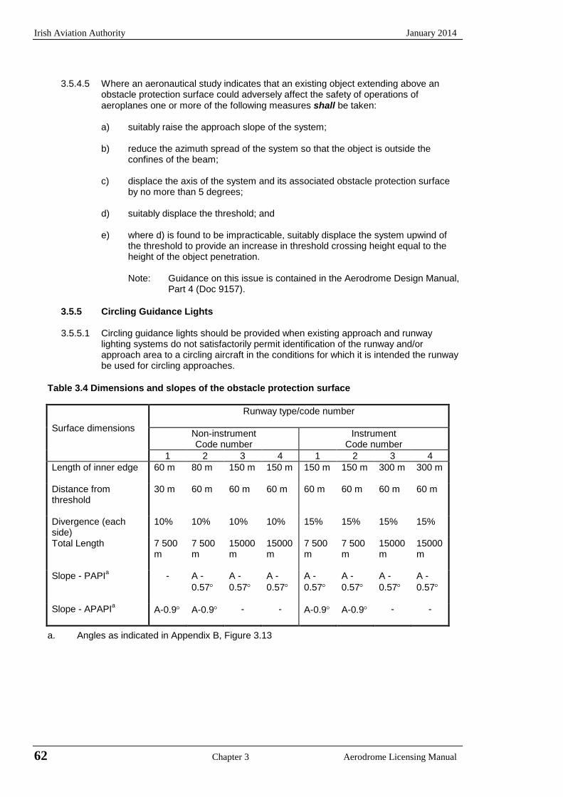
Irish Aviation Authority January 2014
3.5.4.5 Where an aeronautical study indicates that an existing object extending above an
obstacle protection surface could adversely affect the safety of operations of aeroplanes one or more of the following measures shall be taken:
a) suitably raise the approach slope of the system;
b) reduce the azimuth spread of the system so that the object is outside the
confines of the beam; c) displace the axis of the system and its associated obstacle protection surface
by no more than 5 degrees; d) suitably displace the threshold; and e) where d) is found to be impracticable, suitably displace the system upwind of
the threshold to provide an increase in threshold crossing height equal to the height of the object penetration.
Note: Guidance on this issue is contained in the Aerodrome Design Manual,
Part 4 (Doc 9157).
3.5.5 Circling Guidance Lights
3.5.5.1 Circling guidance lights should be provided when existing approach and runway lighting systems do not satisfactorily permit identification of the runway and/or approach area to a circling aircraft in the conditions for which it is intended the runway be used for circling approaches.
Table 3.4 Dimensions and slopes of the obstacle protection surface
Surface dimensions
Runway type/code number
Non-instrument Code number
Instrument Code number
1 2 3 4 1 2 3 4 Length of inner edge 60 m 80 m 150 m 150 m 150 m 150 m 300 m 300 m
Distance from threshold
30 m 60 m 60 m 60 m 60 m 60 m 60 m 60 m
Divergence (each side)
10% 10% 10% 10% 15% 15% 15% 15%
Total Length 7 500 m
7 500 m
15000 m
15000 m
7 500 m
7 500 m
15000 m
15000 m
Slope - PAPIa - A -0.57°
A -0.57°
A -0.57°
A -0.57°
A -0.57°
A -0.57°
A -0.57°
Slope - APAPIa A-0.9° A-0.9° - - A-0.9° A-0.9° - -
a. Angles as indicated in Appendix B, Figure 3.13
62 Chapter 3 Aerodrome Licensing Manual
January 2014 Irish Aviation Authority
3.5.5.2 The location and number of circling guidance lights should be adequate to enable a pilot, as appropriate to:
a) join the downwind leg or align and adjust the aircraft’s track to the runway
at a required distance from it and to distinguish the threshold in passing; and
b) keep in sight the runway threshold and/or other features which will make
it possible to judge the turn onto base leg and final approach, taking into account the guidance provided by other visual aids.
3.5.5.3 Circling guidance lights should consist of:
a) lights indicating the extended centre line of the runway and/or parts of
any approach lighting system; or
b) lights indicating the position of the runway threshold; or
c) lights indicating the direction or location of the runway;
or a combination of such lights as is appropriate to the runway under consideration.
Note Guidance on the installation of circling guidance lights is given in the Aerodrome
Design Manual, Part 4.
3.5.5.4 Circling guidance lights should be fixed or flashing lights of an intensity and beam spread adequate for the conditions of visibility and ambient light in which it is intended to make visual circling approaches. The flashing lights should be white and the steady lights either white or gaseous discharge lights.
3.5.5.5 The lights should be designed and installed in such a manner that they will not
dazzle or confuse a pilot when approaching to land, taking-off or taxiing.
3.6 Runway Lighting Systems
3.6.1 Runway lead-in lighting systems
3.6.1.1 A runway lead-in lighting system should be provided where it is desired to provide visual guidance along a specific approach path, for reasons such as avoiding hazardous terrain or for purposes of noise abatement.
Note Guidance on providing lead-in lighting systems is given in the Aerodrome Design Manual, Part 4 (Doc 9157).
3.6.1.2 A runway lead-in lighting system should consist of groups of lights positioned so as to define the desired approach path and so that one group may be sighted from the preceding group. The interval between adjacent groups should not exceed approximately 1 600 m.
Note Runway lead-in lighting systems may be curved, straight, or a combination thereof.
3.6.1.3 A runway lead-in lighting system should extend from a point as determined by the appropriate authority, up to a point where the approach lighting system, if provided, or the runway or the runway lighting system is in view.
3.6.1.4 Each group of lights of a runway lead-in lighting system should consist of at least three flashing lights in a linear or cluster configuration. The system may be augmented by steady burning lights where such lights would assist in identifying the system.
Aerodrome Licensing Manual Chapter 3 63
Irish Aviation Authority January 2014
3.6.1.5 The flashing lights should be white, and the steady burning lights gaseous
discharge lights.
3.6.1.6 Where practicable, the flashing lights in each group should flash in sequence towards the runway.
3.6.2 Runway threshold identification lights
3.6.2.1 Runway threshold identification lights should be installed:
a) at the threshold of an non-precision approach runway when additional
threshold conspicuity is necessary or where it is not practicable to provide other approach lighting aids; and
b) where a runway threshold is permanently displaced from the runway extremity or temporarily displaced from the normal position and additional threshold conspicuity is necessary.
3.6.2.2 Runway threshold identification lights shall be located symmetrically about the
runway centre line, in line with the threshold and approximately 10 m outside each line of runway edge lights.
3.6.2.3 Runway threshold identification lights should be flashing white lights with a flash
frequency between 60 and 120 per minute.
3.6.2.4 The lights shall be visible only in the direction of approach to the runway.
3.6.3 Runway edge lights
3.6.3.1 Runway edge lights shall be provided for a runway intended for use at night or for a precision approach runway intended for use by day or night.
3.6.3.2 Runway edge lights should be provided on a runway intended for take-off with
an operating minimum below an RVR of the order of 800 m by day.
3.6.3.3 Runway edge lights shall be placed along the full length of the runway and shall be in two parallel rows equidistant from the centre line.
3.6.3.4 Runway edge lights shall be placed along the edges of the area declared for
use as the runway or outside the edges of the area at a distance of not more than 3 m.
3.6.3.5 Where the width of the area which could be declared as runway exceeds 60 m,
the distance between the rows of lights should be determined taking into account the nature of the operations, the light distribution characteristics of the runway edge lights and other visual aids serving the runway.
3.6.3.6 The lights shall be uniformly spaced in rows at intervals of not more than 60 m
for an instrument runway, and at intervals of not more than 100 m for a non-instrument runway. The lights on opposite sides of the runway shall be on lines at right angles to that axis. At intersections of runways, lights may be spaced irregularly or omitted, provided that adequate guidance remains available to the pilot.
64 Chapter 3 Aerodrome Licensing Manual
January 2014 Irish Aviation Authority
3.6.3.7 Runway edge lights shall be fixed lights showing variable white, except that:
a) in the case of a displaced threshold, the lights between the beginning of the runway and the displaced threshold shall show red in the approach direction; and
b) a section of the lights 600 m or one-third of the runway length, whichever
is the less, at the remote end of the runway from the end at which the take-off run is started may show yellow.
3.6.3.8 The runway edge lights shall show at all angles in azimuth necessary to provide
guidance to a pilot landing or taking-off in either direction. When the runway edge lights are intended to provide circling guidance, they shall show at all angles of azimuth.
3.6.3.9 In all angles of azimuth required in 3.8.3.8, runway edge lights shall show at
angles up to 15 degrees above the horizontal with an intensity adequate for the conditions of visibility and ambient light in which the use of the runway for take-off and landing is intended. In any case, the intensity shall be at least 50 cd except that at an aerodrome without extraneous lighting the intensity of lights may be reduced to no less than 25 cd to avoid dazzling the pilot.
3.6.3.10 Runway edge lights on a precision approach runway shall be in accordance
with the specifications of Annex 14, Appendix 2, Figures 2.9 and 2.10.
3.6.4 Runway threshold and wing bar lights
3.6.4.1 Runway threshold lights shall be provided for a runway equipped with runway edge lights except on a non-instrument runway or non-precision approach runway where the threshold is displaced and wing bar lights are provided.
3.6.4.2 When a threshold is at the extremity of a runway, the threshold lights shall be
placed in a row at right angles to the runway axis as near to the extremity of the runway as possible and, in any case, not more than 3 m outside the extremity.
3.6.4.3 When a threshold is displaced from the extremity of a runway, the threshold
lights shall be placed in a row at right angles to the runway axis at the displaced threshold.
3.6.4.4 Threshold lighting shall consist of:
a) on an non-instrument or non-precision approach runway, at least six
lights;
b) on a precision approach runway category I, at least the number of lights that would be required if the lights were uniformly spaced at intervals of 3 m between the rows of runway edge lights; and
c) on a precision approach runway category II or III, lights uniformly spaced
between the rows of runway edge lights at intervals of not more than 3m.
3.6.4.5 The lights prescribed in paragraph 3.6.4.4 a) and b) should be either:
a) equally spaced between the rows of runway edge lights; or
b) symmetrically disposed about the runway centre line in two groups, with the lights uniformly spaced in each group and with a gap between the groups equal to the gauge of the touchdown zone marking or lighting, where such is provided, or otherwise not more than half the distance between the rows of runway edge lights.
Aerodrome Licensing Manual Chapter 3 65
Irish Aviation Authority January 2014
3.6.4.6 Wing bar lights should be provided on a precision approach runway when
additional conspicuity is considered desirable. 3.6.4.7 Wing bar lights shall be provided on a non-instrument or non precision
approach runway where the threshold is displaced and runway threshold lights are required, but are not provided.
3.6.4.8 Wing bar lights shall be symmetrically disposed about the runway centre line at
the threshold in two groups i.e. wing bars. Each wing bar shall be formed by at least five lights extending at least 10 m outward from, and at right angles to, the line of the runway edge lights, with the innermost light of each wing bar in the line of the runway edge lights.
3.6.4.9 Runway threshold and wing bar lights shall be fixed unidirectional lights
showing green in the direction of approach to the runway. The intensity and the beam spread of the lights shall be adequate for the conditions of visibility and ambient light in which use of the runway is intended.
3.6.4.10 Runway threshold lights on a precision approach runway shall be in
accordance with the specifications of Annex 14, Appendix 2, Figure 2.3.
3.6.4.11 Threshold wing bar lights on a precision approach runway shall be in accordance with the specifications of Annex 14, Appendix 2, Figure 2.4.
3.6.5 Runway end lights
3.6.5.1 Runway end lights shall be provided for a runway equipped with runway edge
lights.
Note When the threshold is at the runway extremity fittings serving as threshold lights may be used as runway end lights.
3.6.5.2 Runway end lights shall be placed on a line at right angles to the runway axis
as near to the end of the runway as possible and, in any case, not more than 3m outside the end.
3.6.5.3 Runway end lighting should consist of at least six lights. The lights should be
either:
a) equally spaced between the rows of runway edge lights; or
b) symmetrically disposed about the runway centre line in two groups with the lights uniformly spaced in each group with a gap between the groups of not more than half the distance between the runway edge lights.
For a precision approach runway category III the spacing between runway end lights, except between the innermost lights if a gap is used, should not exceed 6m.
3.6.5.4 Runway end lights shall be fixed unidirectional lights showing red in the direction of the runway. The intensity and beam spread of the lights shall be adequate for the conditions of visibility and ambient light in which use of the runway is intended.
3.6.5.5 Runway end lights on a precision approach runway shall be in accordance with
the specifications of Annex 14, Appendix 2, Figure 2.8
66 Chapter 3 Aerodrome Licensing Manual
January 2014 Irish Aviation Authority
3.6.6 Runway centre line lights
3.6.6.1 Runway centre line lights shall be provided on a precision approach runway category II or III.
3.6.6.2 Runway centre line lights shall be provided on a runway intended to be used for
take-off with an operating minimum below an RVR of the order of 400m.
3.6.6.3 Runway centre line lights should be provided on a precision approach runway category I, particularly when the runway is used by aircraft with high landing speeds or where the width between the runway edge lights is greater than 50m.
3.6.6.4 Runway centre line lights should be provided on a runway intended to be used
for take-off with an operating minimum of an RVR of the order of 400 m or higher when used by aeroplanes with a very high take-off speed, particularly where the width between the runway edge lights is greater than 50m.
3.6.6.5 Runway centre line lights shall be located along the centre line of the runway,
except that the lights may be uniformly offset to the same side of the runway centre line by not more than 60 cm where it is not practicable to locate them along the centre line. The lights shall be located from the threshold to the end at a longitudinal spacing of approximately 15 m. Where the serviceability level of the runway centre line lights specified as maintenance objectives in 3.2.7.7 or 3.2.7.11, as appropriate, can be demonstrated and the runway is intended for use in RVR conditions of 350 m or greater the longitudinal spacing may be approximately 30m.
Note Existing centre line lighting where lights are spaced at 7.5 m need not be
replaced.
3.6.6.6 Centre line guidance for take-off from the beginning of a runway to a displaced threshold should be provided by:
a) an approach lighting system if its characteristics and intensity settings
afford the guidance required during take-off and it does not dazzle the pilot of an aircraft taking-off; or
b) runway centre line lights; or
c) barrettes of at least 3 m in length and spaced at uniform intervals of 30 m
as shown in Appendix 3A, Figure 3A.5 designed so that their photometric characteristics and intensity setting afford the guidance required during take-off without dazzling the pilot of an aircraft taking-off.
Where necessary, provision should be made to extinguish those centre line lights specified in (b) or reset the intensity of the approach lighting system or barrettes when the runway is being used for landing. In no case should only the single source runway centre line lights show from the beginning of the runway to a displaced threshold when the runway is being used for landing.
3.6.6.7 Runway centre line lights shall be fixed lights showing variable white from the
threshold to the point 900 m from the runway end; alternate red and variable white from 900 m to 300 m from the runway end; and red from 300 m to the runway end, except that for runways less than 1800 m in length, the alternate red and variable white lights shall extend from the mid-point of the runway usable for landing to 300 m from the runway end.
Note Care is required in the design of the electrical system to ensure that failure of
part of the electrical system will not result in a false indication of the runway distance remaining.
Aerodrome Licensing Manual Chapter 3 67
Irish Aviation Authority January 2014
3.6.6.8 Runway centre line lights shall be in accordance with the specifications of Annex 14, Appendix 2, Figures 2.6 or 2.7.
3.6.7 Runway touchdown zone lighting
3.6.7.1 Touchdown zone lights shall be provided in the touchdown zone of a precision
approach runway category II or III.
3.6.7.2 Touchdown zone lights shall extend from the threshold for a longitudinal distance of 900 m, except that, on runways less than 1800 m in length, the system shall be shortened so that it does not extend beyond the mid-point of the runway. The pattern shall be formed by pairs of barrettes symmetrically located about the runway centre line. The lateral spacing between the innermost lights of a pair of barrettes shall be equal to the lateral spacing selected for the touchdown zone marking. The longitudinal spacing between pairs of barrettes shall be either 30 m or 60 m.
Note: To allow for operations at lower visibility minima it may be desirable to use a 30
m longitudinal spacing between barrettes.
3.6.7.3 A barrette shall be composed of at least three lights with a spacing between the lights of not more than 1.5 m.
3.6.7.4 A barrette should be not less than 3 m or more than 4.5 m in length.
3.6.7.5 Touchdown zone lights shall be fixed unidirectional lights showing variable
white.
3.6.7.6 Touchdown zone lights shall be in accordance with the specifications of Annex 14, Appendix 2, Figure 2.5
3.6.8 Simple touchdown zone lights
3.6.8.1 Except where TDZ lights are provided in accordance with paragraph 3.6.7, at an
aerodrome where the approach angle is greater than 3.5 degrees and/or the Landing Distance Available combined with other factors increases the risk of an overrun, simple touchdown zone lights should be provided.
3.6.8.2 Simple touchdown zone lights shall be a pair of lights located on each side of the runway centreline 0.3 m beyond the upwind edge of the final touchdown zone marking. The lateral spacing between the inner lights of the two pairs of lights shall be equal to the lateral spacing selected for the touchdown zone marking. The spacing between the lights of the same pair shall not be more than 1.5 m or half the width of the touchdown zone marking, whichever is greater. (See Figure 5-24.)
3.6.8.3 Where provided on a runway without TDZ markings, simple touchdown zone
lights should be installed in such a position that provides the equivalent TDZ information.
3.6.8.4 Simple touchdown zone lights shall be fixed unidirectional lights showing
variable white, aligned so as to be visible to the pilot of a landing aeroplane in the direction of approach to the runway.
3.6.8.5 Simple touchdown zone lights shall be in accordance with the specifications in
Appendix A, Figure 3A-11. Note As a good operating practice, simple touchdown zone lights are supplied with
power on a separate circuit to other runway lighting so that they may be used when other lighting is switched off.
68 Chapter 3 Aerodrome Licensing Manual
January 2014 Irish Aviation Authority
3.6.9 Rapid Exit Taxiway Indicator Lights
3.6.9.1 Rapid exit taxiway indication lights should be provided on a runway intended for use in runway visual range conditions less than a value of 350 m and/or where traffic density is heavy. Note – the purpose of rapid exit taxiway indicator lights (RETIL’s) is to provide pilots with distance-to-go information to the nearest rapid exit taxiway on the runway, to enhance situational awareness in low visibility conditions and enable pilots to apply braking action for more efficient roll-out and runway exit speeds. It is essential that pilots operating at aerodromes with runway(s) displaying rapid exit taxiway indicator lights be familiar with the purpose of these lights.
3.6.9.2 Rapid exit taxiway indicator lights shall not be displayed in the event of any lamp failure or other failure that prevents the display of the light pattern depicted in Fig 3A.7, in full.
3.6.9.3 A set of rapid exit taxiway indicator lights shall be located on the runway on the
same side of the runway centre line as the associated rapid exit taxiway, in the configuration shown in Fig 3A.7. In each set, the lights shall be located 2 m apart and the light nearest to the runway centre line shall be displaced 2 m from the runway centre line.
3.6.9.4 When more than one rapid taxiway exists on a runway, the set of rapid exit
taxiway indicator lights for each exit shall not overlap when displayed.
3.6.9.5 Rapid exit taxiway indicator lights shall be fixed unidirectional yellow lights, aligned so as to be visible to the pilot of a landing aeroplane in the direction of approach to the runway.
3.6.9.6 Rapid exit taxiway indicator lights shall be in accordance with the specifications
in Appendix 2 of Annex 14, Figure A2-6 or Figure A2-7, as appropriate.
3.6.9.7 Rapid exit taxiway indicator lights should be supplied with power on a separate circuit to other runway lighting so that they may be used when other lighting is switched off.
3.6.10 Stopway Lights
3.6.10.1 Stopway lights shall be provided for a stopway intended for use at night.
3.6.10.2 Stopway lights shall be placed along the full length of the stopway and shall be
in two parallel rows that are equidistant from the centre line and coincident with the rows of the runway edge lights. Stopway lights shall also be provided across the end of a stopway on a line at right angles to the stopway axis as near to the end of the stopway as possible, and in any case, not more than 3 m outside the end.
3.6.10.3 Stopway lights shall be fixed unidirectional lights showing red in the direction of
the runway.
3.6.11 Runway Turn Pad Lights 3.6.11.1 Runway turn pad lights shall be provided for continuous guidance on a runway
turn pad intended for use in runway visual range conditions less than a value of 350 m, to enable an aeroplane to complete a 180-degree turn and align with the runway centre line.
3.6.11.2 Runway turn pad lights should be provided on a runway turn pad intended for
use at night.
Aerodrome Licensing Manual Chapter 3 69
Irish Aviation Authority January 2014
3.6.11.3 Runway turn pad lights should normally be located on the runway turn pad
marking, except that they may be offset by not more than 30 cm where it is not practicable to locate them on the marking.
3.6.11.4 Runway turn pad lights on a straight section of the runway turn pad marking
should be spaced at longitudinal intervals of not more than 15 m.
3.6.11.5 Runway turn pad lights on a curved section of the runway turn pad marking should not exceed a spacing of 7.5 m.
3.6.11.6 Runway turn pad lights shall be unidirectional fixed lights showing green with
beam dimensions such that the light is visible only from aeroplanes on or approaching the runway turn pad.
3.6.11.7 Runway turn pad lights shall be in accordance with the specifications of Annex
14, Appendix 2, Figure A2-13, A2-14 or A2-15, as appropriate.
3.7 Taxiway, Apron and Aircraft Stand Lights 3.7.1 Taxiway centre line lights
3.7.1.1 Taxiway centre line lights shall be provided on a exit taxiway, taxiway, de/anti-
icing facility and apron intended for use in RVR conditions less than a value of 350 m in such a manner as to provide continuous guidance between the runway centre line and aircraft stands, except that these lights need not be provided where the traffic density is light and taxiway edge lights and centre line marking provide adequate guidance.
3.7.1.2 Taxiway centre line lights should be provided on a taxiway intended for use at
night in RVR conditions of 350 m or greater, and particularly on complex taxiway intersections and exit taxiways, except that these lights need not be provided where the traffic density is light and taxiway edge lights and centre line marking provide adequate guidance.
Note Where there may be a need to delineate the edges of a taxiway e.g. on a rapid
exit taxiway, narrow taxiway or in snow conditions, this may be done with taxiway edge lights or markers.
3.7.1.3 Taxiway centre line lights should be provided on an exit taxiway, taxiway, de/anti icing facility and apron in all visibility conditions where specified as components of an advanced surface movement guidance and control system in such a manner as to provide continuous guidance between the runway centre line and aircraft stands.
3.7.1.4 Taxiway centre line lights shall be provided on a runway forming part of a
standard taxi-route and intended for taxiing in RVR conditions less than a value of 350 m, except that these lights need not be provided where the traffic density is light and taxiway edge lights and centre line marking provide adequate guidance.
Note See 3.2.5.3 for provisions concerning the interlocking of runway and taxiway
lighting systems.
3.7.1.5 Taxiway centre line lights should be provided in all visibility conditions on a runway forming part of a standard taxi-route where specified as components of an advanced surface movement guidance and control system.
70 Chapter 3 Aerodrome Licensing Manual

January 2014 Irish Aviation Authority
3.7.1.6 Taxiway centre line lights on a taxiway other than an exit taxiway and on a runway forming part of a standard taxi-route shall be fixed lights showing green with beam dimensions such that the light is visible only from aeroplanes on or in the vicinity of the taxiway.
3.7.1.7 Taxiway centre line lights on an exit taxiway shall be fixed lights. Alternate
taxiway centre line lights shall show green and yellow from their beginning near the runway centre line to the perimeter of the ILS/MLS critical/sensitive area or the lower edge of the inner transitional surface, whichever is farthest from the runway; and thereafter all lights shall show green (See Appendix 3A, Figure 3A.6). The light nearest to the perimeter shall always show yellow. Where aircraft may follow the centre line light in both directions all the centre line lights shall show green to aircraft approaching the runway.
Notes 1 Care is necessary to limit the light distribution of green lights on or near the
runway so as to avoid possible confusion with threshold lights. 2 For yellow filter characteristics see Annex 14, Appendix 1, Section 2.2. 3 The size of the ILS/MLS critical/sensitive areas depends on the
characteristics of the associated ILS/MLS and other factors. Guidance is provided in Annex 10, Volume 1,
4 See 4.7.3 for specification on runway vacated signs. 3.7.1.8 Where it is necessary to denote the proximity to a runway, taxiway centre line
lights should be fixed lights showing alternating green and yellow from the perimeter of the ILS/MLS critical/sensitive area or the lower edge of the inner transitional surface, whichever is farthest from the runway, to the runway and continue alternating green and yellow until: a) their end point near the runway centre line; or b) in the case of the taxiway centre line lights crossing the runway, to the
opposite perimeter of the ILS/MLS critical/sensitive area or the lower edge of the inner transitional surface, whichever is farthest from the runway.
Note 1 Care is necessary to limit the light distribution of green lights on or near a
runway so as to avoid possible confusion with threshold lights. Note 2 The provisions of 5.3.17.8 can form part of effective runway incursion
prevention measures.
3.7.1.9 Taxiway centre line lights shall be in accordance with the Annex 14 specifications of:
a) Appendix 2, Figure 2.12, 2.13 or 2.14 for taxiways intended for use in
RVR conditions of less than a value of 350 m; and b) Appendix 2, Figure 2.15 or 2.16 for other taxiways.
3.7.1.10 Where higher intensities are required, from an operational point of view, taxiway centre line lights on rapid exit taxiways intended for use in runway visual range conditions less than a value of 350 m should be in accordance with the specifications of Annex 14, Appendix 2, Figure A2-12. The number of levels of brilliancy settings for these lights should be the same as that for the runway centre line lights.
3.7.1.11 Where taxiway centre line lights are specified as components of an advanced
surface movement guidance and control system and where, from an operational point of view, higher intensities are required to maintain ground movements at a certain speed in very low visibilities or in bright daytime conditions, taxiway centre line lights should be in accordance with the specifications of Annex 14, Appendix 2, Figures 2.17, 2.18 or 2.19.
Aerodrome Licensing Manual Chapter 3 71

Irish Aviation Authority January 2014
Note High intensity centre line lights should only be used in the case of absolute necessity and following a specific study.
3.7.1.12 Taxiway centre line lights should normally be located on the taxiway centre line marking, except that they may be offset by not more than 30 cm where it is not practicable to locate them on the marking.
3.7.1.13 Taxiway centre line lights on a straight section of a taxiway should be spaced at
longitudinal intervals of not more than 30 m, except that:
a) larger intervals not exceeding 60 m may be used where because of the prevailing meteorological conditions, adequate guidance is provided by such spacing;
b) intervals of less than 30 m should be provided on short straight sections;
and
c) on a taxiway intended for use in RVR conditions of less than a value of 350 m the longitudinal spacing should not exceed 15 m.
3.7.1.14 Taxiway centre line lights on a taxiway curve should continue from the straight
portion of the taxiway at a constant distance from the outside edge of the taxiway curve. The lights should be spaced at intervals such that a clear indication of the curve is provided.
3.7.1.15 On a taxiway intended for use in RVR conditions of less than a value of 350 m
the lights on a curve should not exceed a spacing of 15 m and on a curve of less than 400 m radius the lights should be spaced at intervals not greater than 7.5 m. This spacing should extend 60 m before and after the curve.
Note: Spacing on curves that have been found suitable for a taxiway intended for use
in RVR conditions of 350 m or greater are:
Curve radius Light spacing up to 400 m 7.5 m
401 to 899 m 15 m 900 m or greater 30 m
3.7.1.16 Taxiway centre line lights on a rapid exit taxiway should commence at a point at
least 60 m before the beginning of the taxiway centre line curve and continue beyond the end of the curve to a point on the centre line of the taxiway where an aeroplane can be expected to reach normal taxiing speed. The lights on that portion parallel to the runway centre line should always be at least 60 cm from any row of runway centre line lights.
3.7.1.17 The lights should be spaced at longitudinal intervals of not more than 15 m,
except that, where runway centre line lights are not provided, a greater interval not exceeding 30 m may be used.
3.7.1.18 Taxiway centre line lights on exit taxiways other than rapid exit taxiways should
commence at the point where the taxiway centre line marking begins to curve from the runway centre line, and follow the curved taxiway centre line marking at least to the point where the marking leaves the runway. The first light should be at least 60 cm from any row of runway centre line lights. (See Appendix 3A, Figure 3A.8)
3.7.1.19 The lights should be spaced at longitudinal intervals of not more than 7.5 m. 3.7.1.20 Taxiway centre line lights on a runway forming part of a standard taxi route and
intended for taxiing in RVR conditions less than a value of 350 m should be spaced at longitudinal intervals not exceeding 15 m.
72 Chapter 3 Aerodrome Licensing Manual
January 2014 Irish Aviation Authority
3.7.2 Taxiway edge lights 3.7.2.1 Taxiway edge lights shall be provided at the edges of a runway turn pad,
holding bay, de/anti-icing facility, apron, etc. intended for use at night and on a taxiway not provided with taxiway centre line lights and intended for use at night, except that taxiway edge lights need not be provided where, considering the nature of the operations, adequate guidance can be achieved by surface illumination or other means.
3.7.2.2 Taxiway edge lights shall be provided on a runway forming part of a standard
taxi-route and intended for taxiing at night where the runway is not provided with taxiway centre line lights.
Note See 3.2.5.3 for provisions concerning the interlocking of runway and taxiway
lighting systems.
3.7.2.3 Taxiway edge lights on a straight section of a taxiway and on a runway forming part of a standard taxi-route should be spaced at uniform longitudinal intervals of not more than 60 m. The lights on a curve should be spaced at less than 60 m so that a clear indication of a curve is provided.
Note Guidance on the spacing of taxiway edge lights on curves is given in the
Aerodrome Design Manual, Part 4
3.7.2.4 Taxiway edge lights on a holding bay, de/anti-icing facility, apron, etc. should be spaced at uniform longitudinal intervals of not more than 60 m.
3.7.2.5 Taxiway edge lights on a runway turn pad should be spaced at uniform
longitudinal intervals of not more than 30 m.
3.7.2.6 The lights should be located as near as practicable to the edges of the taxiway, runway turn pad, holding bay, de/anti-icing facility, apron or runway, etc. or outside the edges at a distance of not more than 3 m.
3.7.2.7 Taxiway edge lights shall be fixed lights showing blue. The lights shall show up
to at least 75 degrees above the horizontal and at all angles in azimuth necessary to provide guidance to a pilot taxiing in either direction. At an intersection, exit or curve the lights shall be shielded as far as practicable so that they cannot be seen in angles of azimuth in which they may be confused with other lights.
3.7.2.8 The intensity of taxiway edge lights shall be at least 2 cd from 0 degrees to 6
degrees vertical and 0.2 cd at any vertical angle between 6 degrees and 75 degrees.
3.7.3 Stop bars
3.7.3.1 A stop bar shall be provided at every runway-holding position serving a runway
when it is intended that the runway will be used in RVR conditions less than a value of 350 m except where;
a) appropriate aids and procedures are available to assist in preventing
inadvertent incursions of aircraft and vehicles onto the runway; or
b) operational procedures exist to limit, in RVR conditions less than a value of 550 m, the number of ;
(1) aircraft in the manoeuvring area to one at a time; and (2) vehicles on the manoeuvring area to the essential minimum.
Aerodrome Licensing Manual Chapter 3 73
Irish Aviation Authority January 2014
Note: 1 The provision of stop bars requires their control either manually or automatically by air traffic services. Runway incursions may take place in all visibility or weather conditions.
2 The provision of stop bars at runway holding positions and their use at night and in visibility conditions greater than 550 m runway visual range can form part of effective runway incursion prevention measures.
3.7.3.2 A stop bar shall be provided at every runway-holding position serving a runway
when it is intended that the runway will be used in RVR conditions of values between 350 m and 550 m, except where:
a) appropriate aids and procedures are available to assist in preventing
inadvertent incursions of aircraft and vehicles onto the runway; or
b) operational procedures exist to limit in RVR conditions less than a value of 550 m, the number of :
(1) aircraft on the manoeuvring area to one at a time; and (2) vehicles on the manoeuvring to the essential minimum.
3.7.3.3 Where there is more than one stop bar associated with a taxiway/runway
intersection, only one shall be illuminated at any given time.
3.7.3.4 A stop bar should be provided at an intermediate holding position when it is desired to supplement markings with lights and to provide traffic control by visual means.
3.7.3.5 Where the normal stop bar lights might be obscured (from the pilot’s view), for
example, by snow or rain, or where a pilot may be required to stop the aircraft in a position so close to the lights that they are blocked from view by the structure of the aircraft, then a pair of elevated lights should be added to each end of the stop bar.
3.7.3.6 Stop bars shall be located across the taxiway at the point where it desired that
traffic stop. Where the additional lights specified in 3.7.3.4 are provided, these lights shall be located not less than 3 m from the taxiway edge.
3.7.3.7 Stop bars shall consist of lights spaced at intervals of 3 m across the taxiway,
showing red in the intended direction(s) of approach to the intersection or runway-holding position.
3.7.3.8 Stop bars installed at a runway-holding position shall be unidirectional and
shall show red in the direction of approach to the runway.
3.7.3.9 Where additional lights specified in 3.7.3.4 are provided, these lights shall have the same characteristics as the lights in the stop bar, but shall be visible to approaching aircraft up to the stop bar position.
3.7.3.10 Selectively switchable stop bars shall be installed in conjunction with at least
three taxiway centre line lights (extending for a distance of at least 90 m from the stop bar) in the direction that it is intended for an aircraft to proceed from the stop bar.
3.7.3.11 The intensity in red light and beam spreads of stop bar lights shall be in
accordance with the specifications of Annex 14, Appendix 2, Figure 2.12 through 2.16 as appropriate.
74 Chapter 3 Aerodrome Licensing Manual
January 2014 Irish Aviation Authority
3.7.3.12 Where stop bars are specified as components of an advanced surface movement guidance and control system and where, from an operational point of view, higher intensities are required to maintain ground movements at a certain speed in very low visibilities or in bright daytime conditions, the intensity in red light and beam spreads of stop bar lights should be in accordance with the specifications of Annex 14, Appendix 2, Figures 2.17, 2.18, and 2.19).
Note: High intensity stop bars should only be used in case of an absolute necessity and following a specific study.
3.7.3.13 Where a wide beam fixture is required, the intensity in red light and beam spreads of stop bar lights should be in accordance with the specifications of Annex 14, Appendix 2, Figures 2.17, or 2.19.
3.7.3.14 The lighting circuit shall be designed so that:
a) stop bars located across entrance taxiways are selectively switchable;b) stop bars located across taxiways intended to be used only as exit
taxiways are switchable selectively or in groups;c) when a stop bar is illuminated, any taxiway centre line lights installed
beyond the stop bar shall be extinguished for a distance of at least 90 m;and
d) stop bars shall be interlocked with the taxiway centre line lights so thatwhen the centre line lights beyond the stop bar are illuminated the stopbar is extinguished and vice versa.
Note: 1 A stop bar is switched on to indicate that traffic stop and switched off to indicate that traffic proceed. 2 Care is required in the design of the electrical system to ensure that all of the lights of a stop bar will not fail at the same time. Guidance on this issue is given in the Aerodrome Design Manual, Part 5 (Doc 9157).
3.7.4 Intermediate holding position lights
3.7.4.1 Except where a stop bar has been installed, intermediate holding position lights shall be provided at an intermediate holding position intended for use in RVR conditions less than a value of 350 m.
3.7.4.2 Intermediate holding position lights should be provided at an intermediate holding position where there is no need for stop and go signals as provided by a stop bar.
3.7.4.3 Intermediate holding position lights shall be located along the intermediate holding position marking at a distance of 0.3 m prior to the marking.
3.7.4.4 Intermediate holding position lights shall consist of three fixed unidirectional lights showing yellow in the direction of approach to the intermediate holding position with a light distribution similar to taxiway centre line lights if provided. The lights shall be disposed symmetrically about and at right angles to the taxiway centre line, with individual lights spaced 1.5 m apart.
3.7.5 De-icing/anti-icing facility exit lights
3.7.5.1 De-icing/anti-icing facility exit lights should be provided at the exit boundary of a remote de-icing/anti-icing facility adjoining a taxiway
3.7.5.2 De-icing/anti-icing facility exit lights shall be located 0.3 m inward of the intermediate holding position marking displayed at the exit boundary of a remote de-icing/anti-icing facility.
Aerodrome Licensing Manual Chapter 3 75

Irish Aviation Authority January 2014
3.7.5.3 De-icing/anti-icing facility exit lights shall consist of in-pavement fixed unidirectional lights spaced at intervals of 6 m showing yellow in the direction of the approach to the exit boundary with a light distribution similar to taxiway centre line lights.
Note See Appendix 3A, Figure 3A.10
3.7.6 Runway guard lights
3.7.6.1 There are two standard configurations of runway guard lights illustrated in Appendix 3A, Figure 3A.9. Runway guard lights Configuration A, shall be provided at each taxiway/runway intersection associated with a runway intended for use in:
a) RVR conditions less than a value of 550 m where a stop bar is not
installed; and
b) RVR conditions of values between 550 m and 1200 m where the traffic density is heavy.
3.7.6.2 Runway guard lights Configuration A should be provided at each
taxiway/runway intersection associated with a runway intended for use in:
a) RVR conditions of values less than a value of 550 m where a stop bar is installed; and
b) RVR conditions of values between 550 m and 1200 m where the traffic
density is medium or light.
3.7.6.3 Runway guard lights, Configuration A or Configuration B or both, should be provided at each taxiway/runway intersection where enhanced conspicuity of the taxiway/runway intersection is needed such as on a wide throat taxiway, except that Configuration B should not be collocated with a stop bar.
3.7.6.4 Runway guard lights, Configuration A, shall be located at each side of the
taxiway at a distance from the runway centre line not less than that specified for a take-off runway in Table 2.9.
3.7.6.5 Runway guard lights Configuration B shall be located across the taxiway at a
distance from the runway centre line not less than that specified for a take-off runway in Table 2.9.
3.7.6.6 Runway guard lights Configuration A shall consist of consist of two pairs of
yellow lights. 3.7.6.7 Where there is a need to enhance the contrast between the on and off state of
runway guard lights, Configuration A, intended for use during the day, a visor of sufficient size to prevent sunlight from entering the lens without interfering with the function of the fixture, should be located above each lamp.
Note Some other device or design e.g. specially designed optics, may be used
instead of the visor.
3.7.6.8 Runway guard lights, Configuration B, shall consist of yellow lights spaced at intervals of 3 m across the taxiway. The light beam shall be unidirectional and aligned so as to be visible to the pilot of an aeroplane taxiing to the holding position.
3.7.6.9 The light beam shall be unidirectional and aligned so as to be visible to the pilot
of an aeroplane taxiing to the holding position.
76 Chapter 3 Aerodrome Licensing Manual
January 2014 Irish Aviation Authority
3.7.6.10 The intensity in yellow light and beam spreads of lights of Configuration A should be in accordance with the specifications in Annex 14, Appendix 2, Figure 2.24.
3.7.6.11 Where runway guard lights are intended for use during the day, the intensity in
yellow light and beam spreads of lights of Configuration A should be in accordance with the specifications in Annex 14, Appendix 2, Figure 2.25.
3.7.6.12 Where runway guard lights are specified as components of an advanced
surface movement guidance and control system where higher light intensities are required, the intensity in yellow light and beam spreads of lights of configuration A should be in accordance with the specifications in Annex 14, Appendix 2, Figure 2.25.
Note Higher intensities may be required to maintain ground movement at a certain
speed in low visibilities. 3.7.6.13 The intensity in yellow light and beam spreads of lights of Configuration B
should be in accordance with the specifications in Annex 14, Appendix 2, Figure 2.12.
3.7.6.14 Where runway guard lights are intended for use during the day, the intensity in
yellow light and beam spreads of lights of Configuration B should be in accordance with the specifications in Annex 14, Appendix 2, Figure 2.20.
3.7.6.15 Where runway guard lights are specified as components of an advanced
surface movement guidance and control system where higher light intensities are required, the intensity in yellow light and beam spreads of lights of Configuration B should be in accordance with specifications in Annex 14, Appendix 2, Figure A2-20.
3.7.6.16 The lights in each unit of Configuration A shall be illuminated alternately.
3.7.6.17 For Configuration B, adjacent lights shall be alternately illuminated and
alternative lights shall be illuminated in unison. 3.7.6.18 The lights shall be illuminated between 30 and 60 cycles per minute and the
light suppression and illumination periods shall be equal and opposite in each light.
Note: The optimum flash rate is dependent on the rise and fall times of the lamps used. Runway guard lights configuration A, installed on 6.6A circuits have been found to look best when operated at 45 to 50 flashes per minute per lamp. Runway guard lights, Configuration B installed on 6.6A circuits have been found to look best when operated at 30 to 32 flashes per minute per lamp.
Aerodrome Licensing Manual Chapter 3 77
Irish Aviation Authority January 2014
3.7.7 Apron floodlighting
3.7.7.1 Apron flood lighting should be provided on an apron, on a de-icing/anti-icing facility and on a designated isolated aircraft parking position intended to be used at night.
Notes: 1 Where a de-icing/anti-icing facility is located in close proximity to the
runway and permanent floodlighting could be confusing to pilots; other means of illumination of the facility may be required.
2 The designation of an isolated aircraft parking position is specified in Section 2.7.
3 Guidance on apron floodlighting is given in the Aerodrome Design Manual, Part 4.
3.7.7.2 Apron flood lights should be located so as to provide adequate illumination on all apron service areas, with a minimum of glare to pilots of aircraft in flight and on the ground, aerodrome and apron controllers, and personnel on the apron. The arrangement and aiming of floodlights should be such that an aircraft stand receives light from two or more directions to minimise shadows.
3.7.7.3 The spectral distribution of apron floodlights shall be such that the colours used
for aircraft marking connected with routine servicing, and for surface and obstacle marking, can be correctly identified.
3.7.7.4 The average illuminance should at least be the following:
aircraft stand:
- horizontal illuminance - 20 lux with a uniformity ratio (average to minimum) of not more than 4 to 1; and
- vertical illuminance - 20 lux at a height of 2 m above the apron in relevant directions.
other apron areas:
- horizontal illuminance - 50% of the average illuminance on the aircraft stands with a uniformity ratio (average to minimum) of not more than 4 to 1.
3.7.8 Visual docking guidance system
3.7.8.1 A visual docking guidance system shall be provided when it is intended to
indicate, by a visual aid, the precise positioning of an aircraft on an aircraft stand and other alternative means, such as marshallers, are not practicable.
Note: The factors to be considered in evaluating the need for a visual docking
guidance system are in particular: the number and type(s) of aircraft using the aircraft stand, weather conditions, space available on the apron and the precision required for manoeuvring into the parking position due to aircraft servicing installation, passenger loading bridges, etc. See the Aerodrome Design Manual, Part 4 (Doc 9157) for guidance on the selection of suitable systems.
3.7.8.2 The system shall provide both azimuth and stopping guidance.
78 Chapter 3 Aerodrome Licensing Manual
January 2014 Irish Aviation Authority
3.7.8.3 The azimuth guidance unit and the stopping position indicator shall be adequate for use in all weather, visibility, background lighting and pavement conditions for which the system is intended both by day and night, but shall not dazzle the pilot.
Note Care is required in both the design and on-site installation of the system to
ensure that the reflection of sunlight or other light in the vicinity does not degrade the clarity and conspicuity of the visual cues provided by the system.
3.7.8.4 The azimuth guidance unit and the stopping position indicator shall be of a design such that:
a) a clear indication of malfunction of either or both is available to the pilot;
and b) they can be turned off.
3.7.8.5 The azimuth guidance unit and the stopping position indicator shall be located
in such a way that there is continuity of guidance between the aircraft stand markings, the aircraft stand manoeuvring guidance lights, if present, and the visual docking guidance system.
3.7.8.6 The accuracy of the system shall be adequate for the type of loading bridge
and fixed aircraft servicing installations with which it is to be used.
3.7.8.7 The system should be usable by all types of aircraft for which the aircraft stand is intended, preferably without selective operation.
3.7.8.8 If selective operation is required to prepare the system for use by a particular
type of aircraft, then the system shall provide an identification of the selected aircraft type to both the pilot and the system operator as a means of ensuring that the system has been set properly.
3.7.8.9 The azimuth guidance unit shall be located on or close to the extension of the
stand centre line ahead of the aircraft so that its signals are visible from the cockpit of an aircraft throughout the docking manoeuvring and aligned for use at least by the pilot occupying the left seat.
3.7.8.10 The azimuth guidance unit should be aligned for use by the pilots occupying
both the left and right seats.
3.7.8.11 The azimuth guidance unit shall provide unambiguous left/right guidance which enables the pilot to acquire and maintain the lead-in line without overcontrolling.
3.7.8.12 When azimuth guidance is indicated by colour change, green shall be used to
identify the centre line and red for deviations from the centre line.
3.7.8.13 The stopping position indicator shall be located in conjunction with, or sufficiently close to, the azimuth guidance unit so that the pilot can observe both the azimuth and stop signals without turning the head.
3.7.8.14 The stopping position indicator shall be usable at least by the pilot occupying
the left seat.
3.7.8.15 The stopping position indicator should be usable by the pilots occupying both the left and right seats.
3.7.8.16 The stopping position information provided by the indicator for a particular
aircraft type shall account for the anticipated range of variations in pilot eye height and/or viewing angle.
Aerodrome Licensing Manual Chapter 3 79
Irish Aviation Authority January 2014
3.7.8.17 The stopping position indicator shall show the stopping position for the aircraft for which guidance is being provided, and shall provide closing rate information to enable the pilot to gradually decelerate the aircraft to a full stop at the intended stopping position.
3.7.8.18 The stopping position indicator should provide closing rate information over a
distance of at least 10 m.
3.7.8.19 When stopping guidance is indicated by colour change, green shall be used to show that the aircraft can proceed and red to show the stop point has been reached except that for a short distance prior to the stop point a third colour may be used to warn that the stopping point is close.
3.7.9 Advanced Visual Docking Guidance System (A-VDGS)
3.7.9.1 An A-VDGS should be provided where it is operationally desirable to confirm the
correct aircraft type for which guidance is being provided, and/or to indicate the stand centre line in use, where more than one is provided for.
Note 1 Advanced visual docking guidance systems (A-VDGS) include those
systems that, in addition to basic and passive azimuth and stop position information, provide pilots with active (usually sensor-based) guidance information, such as aircraft type indication (in accordance with ICAO Document 8643), distance-to-go information and closing speed. Docking guidance information is usually provided on a single display unit.
Note 2 An A-VDGS may provide docking guidance information in three stages: the acquisition of the aircraft by the system, the azimuth alignment of the aircraft, and the stopping position information.
3.7.9.2 The A-VDGS shall be suitable for use by all types of aircraft for which the
aircraft stand is intended. 3.7.9.3 The AVDGS shall only be used in conditions in which its operational
performance is specified. Note 1 The use of the A-VDGS in conditions such as weather, visibility, and
background lighting both by day and by night would need to be specified.
Note 2 care is required in both the design and on-site installation of the system to ensure that glare, reflection of sunlight, or other light in the vicinity, does not degrade the clarity and conspicuity of the visual cues provided by the system.
3.7.9.4 The docking guidance information provided by an A-VDGS shall not conflict with that provided by a conventional visual docking guidance system on an aircraft stand if both types are provided and are in operational use. A method of indicating that the A-VDGS is not in operational use or unserviceable, shall be provided.
3.7.9.5 The A-VDGS shall be located such that unobstructed and unambiguous
guidance is provided to the person responsible for, and persons assisting, the docking of the aircraft throughout the docking manoeuvre.
Note Usually the pilot-in-command is responsible for the docking of the aircraft.
However, in some circumstances, another person could be responsible and this person may be the driver of a vehicle that is towing the aircraft.
80 Chapter 3 Aerodrome Licensing Manual
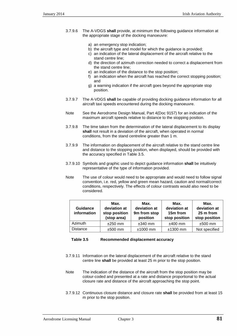
January 2014 Irish Aviation Authority
3.7.9.6 The A-VDGS shall provide, at minimum the following guidance information at the appropriate stage of the docking manoeuvre:
a) an emergency stop indication; b) the aircraft type and model for which the guidance is provided; c) an indication of the lateral displacement of the aircraft relative to the
stand centre line; d) the direction of azimuth correction needed to correct a displacement from
the stand centre line; e) an indication of the distance to the stop position; f) an indication when the aircraft has reached the correct stopping position;
and g) a warning indication if the aircraft goes beyond the appropriate stop
position.
3.7.9.7 The A-VDGS shall be capable of providing docking guidance information for all aircraft taxi speeds encountered during the docking manoeuvre.
Note See the Aerodrome Design Manual, Part 4(Doc 9157) for an indication of the maximum aircraft speeds relative to distance to the stopping position.
3.7.9.8 The time taken from the determination of the lateral displacement to its display shall not result in a deviation of the aircraft, when operated in normal conditions, from the stand centreline greater than 1 m.
3.7.9.9 The information on displacement of the aircraft relative to the stand centre line
and distance to the stopping position, when displayed, should be provided with the accuracy specified in Table 3.5.
3.7.9.10 Symbols and graphic used to depict guidance information shall be intuitively
representative of the type of information provided.
Note The use of colour would need to be appropriate and would need to follow signal convention, i.e. red, yellow and green mean hazard, caution and normal/correct conditions, respectively. The effects of colour contrasts would also need to be considered.
Guidance information
Max. deviation at
stop position (stop area)
Max. deviation at
9m from stop position
Max. deviation at 15m from
stop position
Max. deviation at 25 m from
stop position Azimuth ±250 mm ±340 mm ±400 mm ±500 mm Distance ±500 mm ±1000 mm ±1300 mm Not specified
Table 3.5 Recommended displacement accuracy
3.7.9.11 Information on the lateral displacement of the aircraft relative to the stand centre line shall be provided at least 25 m prior to the stop position.
Note The indication of the distance of the aircraft from the stop position may be colour-coded and presented at a rate and distance proportional to the actual closure rate and distance of the aircraft approaching the stop point.
3.7.9.12 Continuous closure distance and closure rate shall be provided from at least 15
m prior to the stop position.
Aerodrome Licensing Manual Chapter 3 81
Irish Aviation Authority January 2014
3.7.9.13 Where provided, closure distance displayed in numerals should be provided in integers to the stop position and displayed to 1 decimal place at least 3 m prior to the stop position.
3.7.9.14 Throughout the docking manoeuvre, and appropriate means shall be provided on the A-VDGS to indicate the need to bring the aircraft to an immediate halt. In such an event, which includes a failure of the A-VDGS, no other information shall be displayed.
3.7.9.15 Provision to initiate an immediate halt to the docking procedure shall be made
available to personnel responsible for the operational safety of the stand.
3.7.9.16 The word “STOP” in red characters should be displayed when an immediate cessation of the docking manoeuvre is required.
3.7.10 Aircraft stand manoeuvring guidance lights
3.7.10.1 Aircraft stand manoeuvring guidance lights should be provided to facilitate the
positioning of an aircraft on an aircraft stand on a paved apron or on a de/anti-icing facility intended for use in poor visibility conditions, unless adequate guidance is provided by other means.
3.7.10.2 Aircraft stand manoeuvring guidance lights shall be collocated with aircraft
stand markings.
3.7.10.3 Aircraft stand manoeuvring guidance lights, other than those indicating a stop position shall be fixed yellow lights, visible throughout the segments within which they are intended to provide guidance.
3.7.10.4 The lights used to delineate lead-in, turning and lead-out lines should be spaced
at intervals of not more than 7.5 m on curves and 15 m on straight sections. 3.7.10.5 The lights indicating a stop position shall be fixed unidirectional lights, showing
red. 3.7.10.6 The intensity of the lights should be adequate for the condition of visibility and
ambient light in which the use of the aircraft stand is intended. 3.7.10.7 The lighting circuit should be designed so that the lights may be switched on to
indicate that an aircraft stand is to be used and switched off to indicate that it is not to be used.
3.7.11 Road-holding position light
3.7.11.1 A road-holding position light shall be provided at each road-holding position
serving a runway when it is intended that the runway will be used in RVR conditions less than a value of 350 m.
3.7.11.2 A road-holding position light should be provided at each road-holding position
serving a runway when it is intended that the runway will be used in RVR conditions of values between 350 m and 550 m.
3.7.11.3 A road-holding position light shall be located adjacent to the holding position
marking 1.5 m (± 0.5 m) from one edge of the road, i.e. left or right as appropriate to the local traffic regulations.
Note See Section 7.9 the mass and height limitations and frangibility requirements of
navigation aids located on runway strips.
82 Chapter 3 Aerodrome Licensing Manual

January 2014 Irish Aviation Authority
3.7.11.4 The road-holding position light shall comprise:
a) a controllable red (stop) and green (go) traffic light; or
b) a flashing red light.
Note: It is intended that the lights specified in (a) be controlled by air traffic services.
3.7.11.5 The road-holding position light beam shall be unidirectional and aligned so as to be visible to the driver of a vehicle approaching the holding position.
3.7.11.6 The intensity of the light beam shall be adequate for the conditions of visibility
and ambient light in which the use of the holding position is intended, but shall not dazzle the driver.
Note The commonly used traffic lights are likely to meet the requirements in 3.7.11.5
and 3.7.11.6
3.7.11.7 The flash frequency of the flashing-red light shall be between 30 and 60 per minute.
3.7.12 No-entry bar
Note 1 A no-entry bar is intended to be controlled manually by air traffic services.
2 Runway incursions may take place in all visibility or weather conditions. The provision of no-entry bars at taxiway/runway intersections and their use at night and in all visibility conditions can form part of effective runway incursion prevention measures.
3.7.12.1 A no-entry bar should be provided across a taxiway which is intended to be
used as an exit only taxiway to assist in preventing inadvertent access of traffic to that taxiway.
3.7.12.2 A no-entry bar should be located across the taxiway at the end of an exit only
taxiway where it is desired to prevent traffic from entering the taxiway in the wrong direction.
3.7.12.3 A no-entry bar should consist of unidirectional lights spaced at uniform intervals
of no more than 3 m showing red in the intended direction(s) of approach to the runway.
3.7.12.4 A pair of elevated lights should be added to each end of the no-entry bar where
the in pavement no entry bar lights might be obscured from a pilot’s view, for example, by snow or rain, or where a pilot may be required to stop the aircraft in a position so close to the lights that they are blocked from view by the structure of the aircraft.
3.7.12.5 The intensity in red light and beam spreads of no-entry bar lights shall be in
accordance with the specifications in Annex 14, Appendix 2, Figures A2-12 through A2-16, as appropriate.
3.7.12.6 Where no-entry bars are specified as components of an advanced surface
movement guidance and control system and where, from an operational point of view, higher intensities are required to maintain ground movements at a certain speed in very low visibilities or in bright daytime conditions, the intensity in red light and beam spreads of no-entry bar lights should be in accordance with the specifications of Annex 14, Appendix 2, Figure A2-17, A2-18 or A2-19.
3.7.12.7 Where a wide beam fixture is required, the intensity in red light and beam
spreads of no-entry bar lights should be in accordance with the specifications of Annex 14, Appendix 2, Figure A2-17 or A2-19.
Aerodrome Licensing Manual Chapter 3 83
Irish Aviation Authority January 2014
3.7.12.8 The lighting circuit shall be designed so that: a) no-entry bars are switchable selectively or in groups; b) when a no-entry bar is illuminated, any taxiway centre line lights installed
beyond the no-entry bar, when viewed towards the runway, shall be extinguished for a distance of at least 90 m; and
c) when a no-entry bar is illuminated, any stop bar installed between the no-entry bar and the runway shall be extinguished.
3.8 Flight Checking of Visual Aids
3.8.1 Flight checking of visual aids shall be carried out at regular intervals. Subject to
3.9.3, the checking should be carried out as part of the aerodromes routine non-visual aid flight checking process.
3.8.2 For simplicity in presentation, execution and reporting, a flight checking
procedure should be developed. Approach lighting systems, PAPI or APAPI, threshold lights, touchdown zone lights, runway edge lights and runway centre line lights should be checked for failures and misalignments. The PAPI or APAPI systems should be checked for compatibility with the non-visual approach systems. The lighting intensity control system should also be tested. Obstacle lighting on and in the immediate vicinity of the aerodrome should be checked for outages. The location/identification beacon should be checked for correct functioning and the presence of any dangerous or confusing lights noted.
Notes: 1 See Airport Services Manual, Part 8 (Doc 9137) for guidance on the flight
checks of visual aids. 2 Flight checks should not be carried out in weather conditions worse than
cloud ceiling 1500 ft QFE and visibility 10 km. 3.8.3 Before any new lighting installations are brought into use or when there have
been substantial changes to existing installations, flight checking should be carried out. In addition, after major maintenance or new development which may impact on the visibility of visual aids within the movement area, flight checking should be carried out.
84 Chapter 3 Aerodrome Licensing Manual
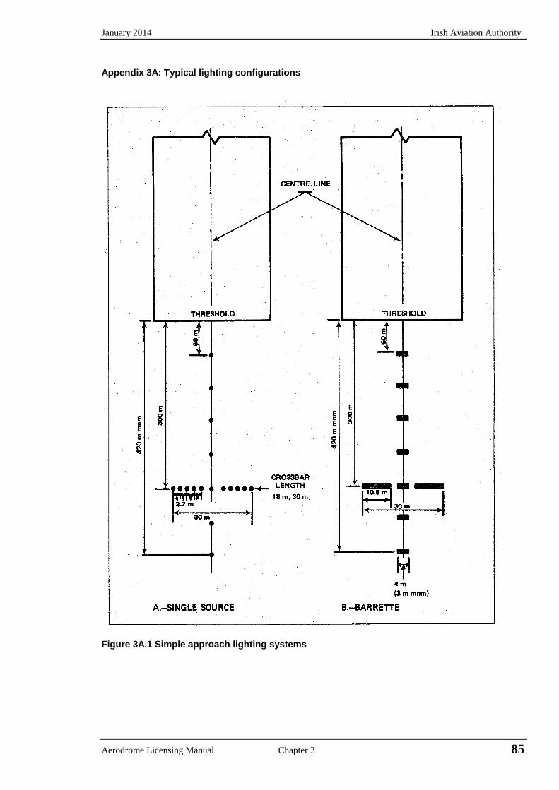
January 2014 Irish Aviation Authority
Appendix 3A: Typical lighting configurations
Figure 3A.1 Simple approach lighting systems
Aerodrome Licensing Manual Chapter 3 85
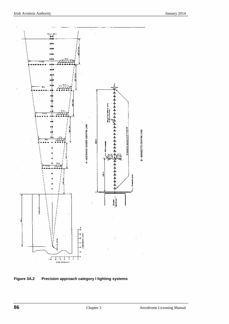
Irish Aviation Authority January 2014
Figure 3A.2 Precision approach category I lighting systems
86 Chapter 3 Aerodrome Licensing Manual
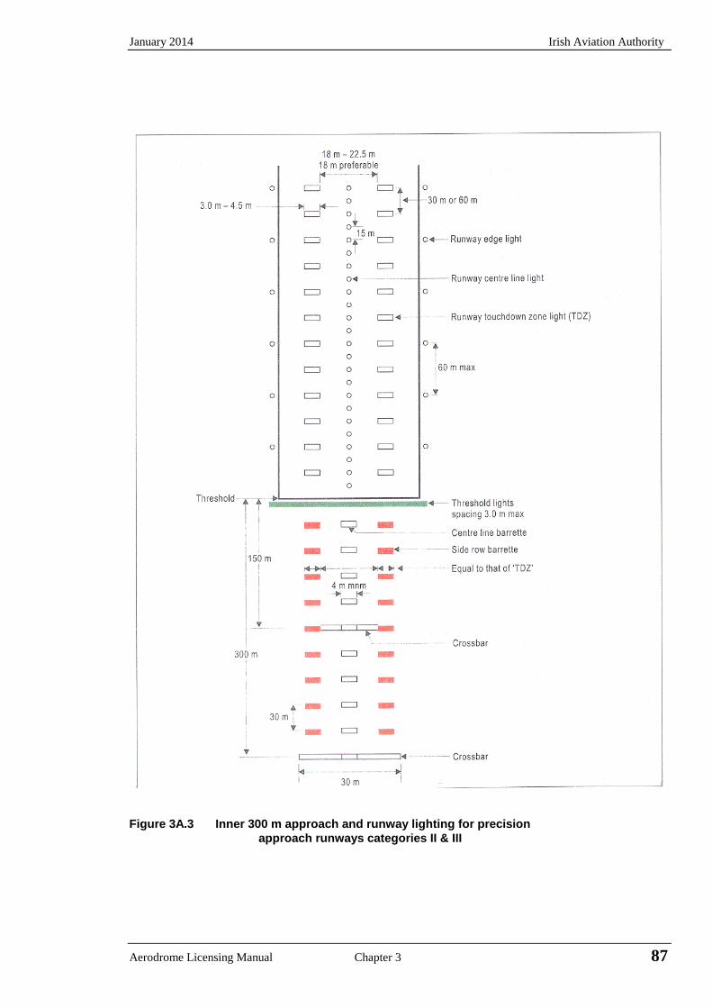
January 2014 Irish Aviation Authority
Figure 3A.3 Inner 300 m approach and runway lighting for precision approach runways categories II & III
Aerodrome Licensing Manual Chapter 3 87
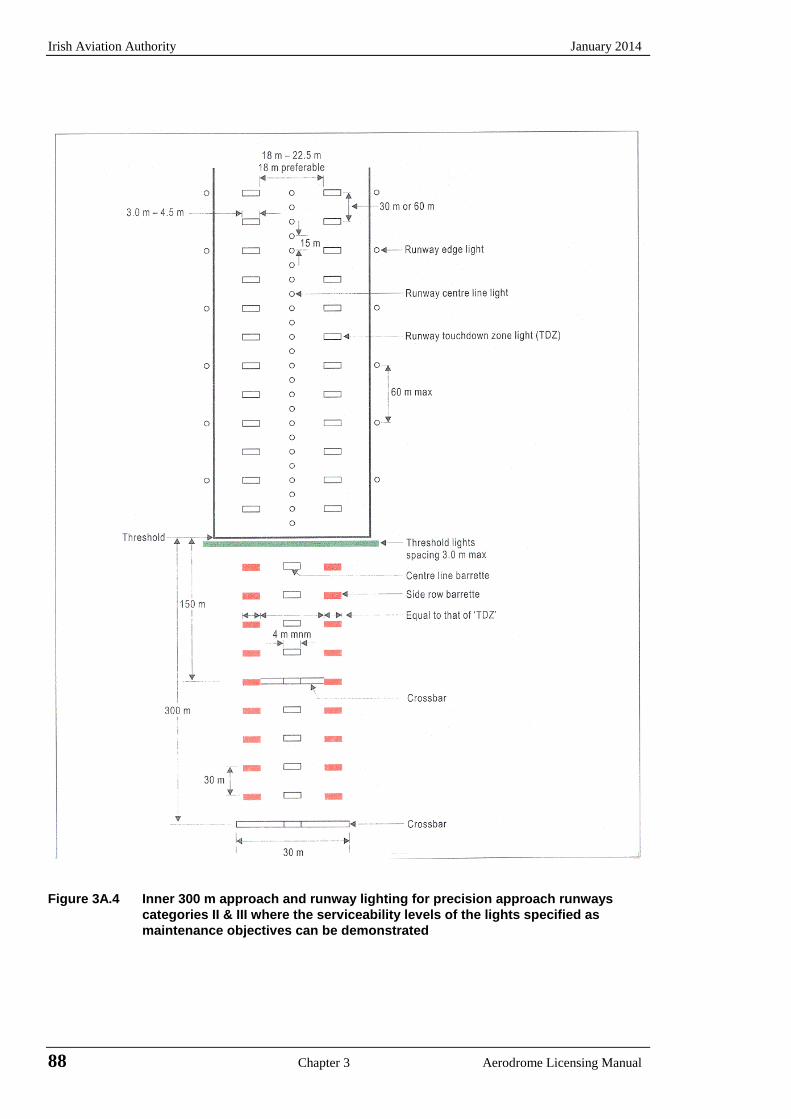
Irish Aviation Authority January 2014
Figure 3A.4 Inner 300 m approach and runway lighting for precision approach runways
categories II & III where the serviceability levels of the lights specified as maintenance objectives can be demonstrated
88 Chapter 3 Aerodrome Licensing Manual
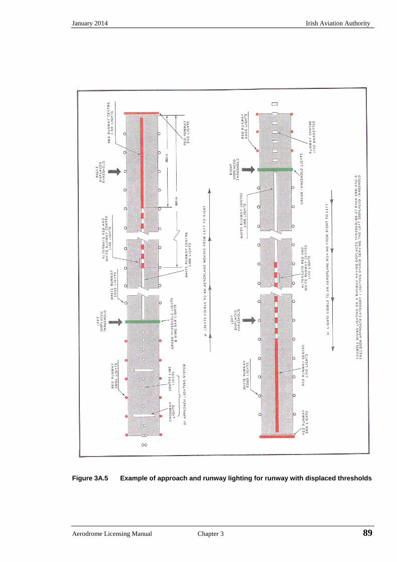
January 2014 Irish Aviation Authority
Figure 3A.5 Example of approach and runway lighting for runway with displaced thresholds
Aerodrome Licensing Manual Chapter 3 89
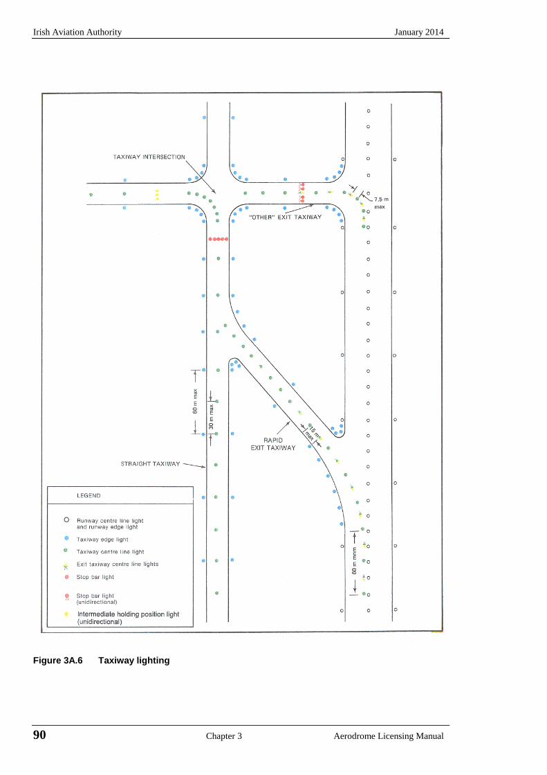
Irish Aviation Authority January 2014
Figure 3A.6 Taxiway lighting
90 Chapter 3 Aerodrome Licensing Manual
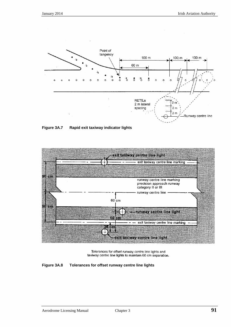
January 2014 Irish Aviation Authority
Figure 3A.7 Rapid exit taxiway indicator lights
Figure 3A.8 Tolerances for offset runway centre line lights
Aerodrome Licensing Manual Chapter 3 91
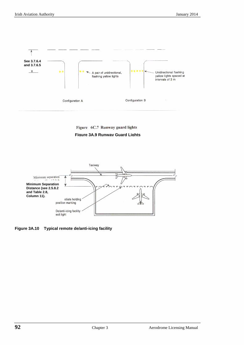
Irish Aviation Authority January 2014
Figure 3A.10 Typical remote de/anti-icing facility
Figure 3A.9 Runway Guard Lights
See 3.7.6.4 and 3.7.6.5
Minimum Separation Distance (see 2.5.8.2 and Table 2.8, Column 11).
92 Chapter 3 Aerodrome Licensing Manual

January 2014 Irish Aviation Authority
Figure 3A-11 Simple touchdown zone lighting
Aerodrome Licensing Manual Chapter 3 93

Irish Aviation Authority January 2014
INTENTIONALLY BLANK
94 Chapter 3 Aerodrome Licensing Manual

January 2014 Irish Aviation Authority
APPENDIX 3B PAPI and APAPI
Figure 3B.1 Siting of PAPI and APAPI and installation tolerances Installation tolerances (a) Where a PAPI or APAPI is installed on a runway not equipped with an ILS or MLS the
distance D1 shall be calculated to ensure that the lowest height at which a pilot will see a correct approach path indication (Figure 3B.2, Angle B for a PAPI and angle A for APAPI) provides the wheel clearance over the threshold specified in Table 3B.1 for the most demanding of aeroplanes regularly using the runway.
(b) Where a PAPI or APAPI is installed on a runway equipped with an ILS or MLS the distance
D1 shall be calculated to provide the optimum compatibility between the visual and non-visual aids for the range of eye to antenna heights of the aeroplanes regularly using the runway. The distance shall be equal to that between the threshold and the effective origin of the ILS glide path or MLS minimum glide path, as appropriate, plus a correction factor for the variation of eye to antenna height of the aeroplanes concerned. The correction factor is obtained by multiplying the average eye to antenna height of those aeroplanes by the cotangent of the approach angle. However, the distance shall be such that in no case will the wheel clearance over the threshold be lower than that specified in Column 3 of Table 3B.1.
Note - Guidance on harmonisation of PAPI, ILS and/or MLS signals is contained in the Aerodrome
Design Manual, Part 4.
(c) If a wheel clearance greater than that specified in (a) above is required for specific aircraft, this can be achieved by increasing D1.
(d) Distance D1 shall be adjusted to compensate for differences in elevation between the lens
centre of the light units and the threshold.
Aerodrome Licensing Manual Chapter 3 95

Irish Aviation Authority January 2014
(e) To ensure that units are mounted as low as possible and to allow for any transverse slope, small height adjustments of up to 5 cm between units are acceptable. A lateral gradient not greater than 1.25% can be accepted provided it is uniformly applied across the units.
(f) A spacing of 6 m (± 1m) between PAPI units should be used on code numbers 1 and 2. In
such an event, the inner PAPI unit shall be located not less than 10 m (± 1m) from the runway edge.
Note - Reducing the spacing between the light units results in a reduction in usable range of the
system. (g) The lateral spacing between APAPI units may be increased to 9 m (± 1 m) if greater range
is required or later conversion to a full PAPI system is anticipated. In the latter case the inner APAPI unit should be located 15 m (± 1m) from the runway edge.
Eye wheel height of aeroplane in approach configuration a
(1)
Desired wheel clearance b,
c
(2)
Minimum wheel clearance d
(3)
Up to but not including 3 m
6 m 3 m e
3 m up to but not including 5 m
9 m 4 m
5 m up to but not including 8 m
9 m 5 m
8 m up to but not including 14 m
9 m 6 m
Table 3B.1 Wheel clearance over the threshold for PAPI and APAPI Notes a. In selecting the eye to wheel height group, only aeroplanes meant to use the system on a
regular basis shall be considered. The most demanding amongst such aeroplanes shall determine the eye-to-wheel height group.
b. Where practicable the desired wheel clearances shown in column (2) shall be provided. c. The wheel clearances in column (2) may be reduced to no less than those in column (3)
where an aeronautical study indicates that such reduced wheel clearances are acceptable. d. Where a reduced wheel clearance is provided at a displaced threshold it shall be ensured
that the corresponding desired wheel clearance specified in column (2) will be available when an aeroplane at the top end of the eye-to-wheel height group chosen overflies the extremity of the runway.
e. This wheel clearance may be reduced to 1.5 m on runways used mainly by light weight non-turbo-jet aeroplanes.
96 Chapter 3 Aerodrome Licensing Manual
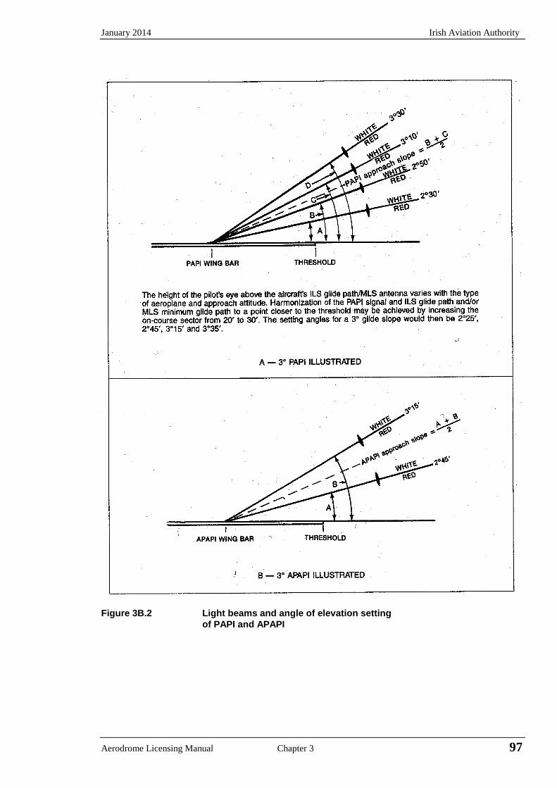
January 2014 Irish Aviation Authority
Figure 3B.2 Light beams and angle of elevation setting of PAPI and APAPI
Aerodrome Licensing Manual Chapter 3 97

Irish Aviation Authority January 2014
INTENTIONALLY BLANK
98 Chapter 3 Aerodrome Licensing Manual
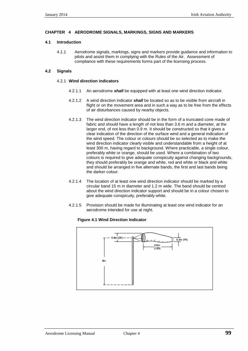
January 2014 Irish Aviation Authority
Aerodrome Licensing Manual Chapter 4 99
CHAPTER 4 AERODROME SIGNALS, MARKINGS, SIGNS AND MARKERS
4.1 Introduction
4.1.1 Aerodrome signals, markings, signs and markers provide guidance and information to
pilots and assist them in complying with the Rules of the Air. Assessment of compliance with these requirements forms part of the licensing process.
4.2 Signals
4.2.1 Wind direction indicators
4.2.1.1 An aerodrome shall be equipped with at least one wind direction indicator.
4.2.1.2 A wind direction indicator shall be located so as to be visible from aircraft in flight or on the movement area and in such a way as to be free from the effects of air disturbances caused by nearby objects.
4.2.1.3 The wind direction indicator should be in the form of a truncated cone made of
fabric and should have a length of not less than 3.6 m and a diameter, at the larger end, of not less than 0.9 m. It should be constructed so that it gives a clear indication of the direction of the surface wind and a general indication of the wind speed. The colour or colours should be so selected as to make the wind direction indicator clearly visible and understandable from a height of at least 300 m, having regard to background. Where practicable, a single colour, preferably white or orange, should be used. Where a combination of two colours is required to give adequate conspicuity against changing backgrounds, they should preferably be orange and white, red and white or black and white and should be arranged in five alternate bands, the first and last bands being the darker colour.
4.2.1.4 The location of at least one wind direction indicator should be marked by a
circular band 15 m in diameter and 1.2 m wide. The band should be centred about the wind direction indicator support and should be in a colour chosen to give adequate conspicuity, preferably white.
4.2.1.5 Provision should be made for illuminating at least one wind indicator for an
aerodrome intended for use at night.
Figure 4.1 Wind Direction Indicator
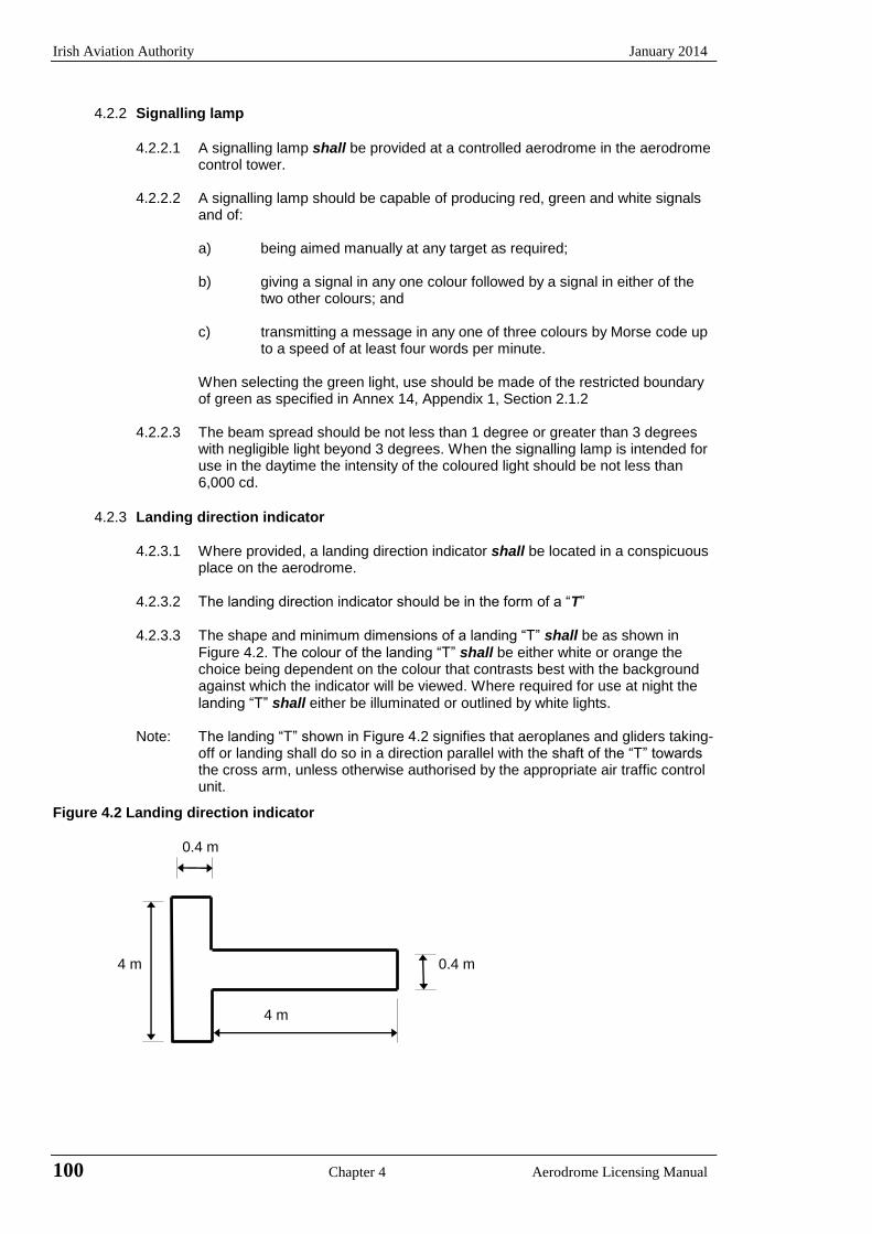
Irish Aviation Authority January 2014
100 Chapter 4 Aerodrome Licensing Manual
4.2.2 Signalling lamp
4.2.2.1 A signalling lamp shall be provided at a controlled aerodrome in the aerodrome control tower.
4.2.2.2 A signalling lamp should be capable of producing red, green and white signals
and of:
a) being aimed manually at any target as required;
b) giving a signal in any one colour followed by a signal in either of the two other colours; and
c) transmitting a message in any one of three colours by Morse code up
to a speed of at least four words per minute.
When selecting the green light, use should be made of the restricted boundary of green as specified in Annex 14, Appendix 1, Section 2.1.2
4.2.2.3 The beam spread should be not less than 1 degree or greater than 3 degrees
with negligible light beyond 3 degrees. When the signalling lamp is intended for use in the daytime the intensity of the coloured light should be not less than 6,000 cd.
4.2.3 Landing direction indicator
4.2.3.1 Where provided, a landing direction indicator shall be located in a conspicuous place on the aerodrome.
4.2.3.2 The landing direction indicator should be in the form of a “T”
4.2.3.3 The shape and minimum dimensions of a landing “T” shall be as shown in
Figure 4.2. The colour of the landing “T” shall be either white or orange the choice being dependent on the colour that contrasts best with the background against which the indicator will be viewed. Where required for use at night the landing “T” shall either be illuminated or outlined by white lights.
Note: The landing “T” shown in Figure 4.2 signifies that aeroplanes and gliders taking-
off or landing shall do so in a direction parallel with the shaft of the “T” towards the cross arm, unless otherwise authorised by the appropriate air traffic control unit.
Figure 4.2 Landing direction indicator
0.4 m 4 m 0.4 m
4 m
January 2014 Irish Aviation Authority
Aerodrome Licensing Manual Chapter 4 101
4.2.4 Signal area and signal panels
4.2.4.1 A signal area need only be provided when it is intended to use visual ground signals to communicate with aircraft in flight. Such signals may be needed when the aerodrome does not have a control tower or an aerodrome flight information service unit, or when the aerodrome is used by aeroplanes not equipped with radio. Visual ground signals may also be useful in the case of failure of two-way radio communication with aircraft. It should be recognised, however, that the type of information that may be conveyed by visual ground signals should normally be available in AIP or NOTAM. The potential need for visual ground signals should therefore be evaluated before deciding to provide a signal area.
4.2.4.2 The signal area should be located so as to be visible for all angles of azimuth
above an angle of 10 degrees above the horizontal when viewed from a height of 300 m.
4.2.4.3 The signal area shall be an even horizontal surface at least 9 m square.
4.2.4.4 The colour of the signal area should be chosen to contrast with the colours of
the signal panels used, and it should be surrounded by a white border not less than 0.3 m wide.
Note Rules of the Air Order and Annex 2, Appendix 1 specifies the shape, colour and
use of visual ground signals. The Aerodrome Design Manual, Part 4 (Doc 9157) provides guidance on their design.
4.3 Markings for Denoting Restricted Use Area
4.3.1 Closed runways and taxiways or parts thereof
4.3.1.1 A closed marking shall be displayed on a runway or taxiway, or portion thereof, which is permanently closed to the use of all aircraft.
4.3.1.2 A closed marking should be displayed on a temporarily closed runway or
taxiway, or portion thereof, except that such marking may be omitted when the closing is of short duration and adequate warning by air traffic services is provided.
4.3.1.3 On a runway a closed marking shall be placed at each end of the runway, or
portion thereof, declared closed, and additional markings shall be so placed that the maximum interval between markings does not exceed 300 m. On a taxiway a closed marking shall be placed at least at each end of the taxiway or portion thereof closed.
4.3.1.4 The closed marking shall be of the form and proportions as detailed in
Appendix 4A, Figure 4A.1, (Illustration a), when displayed on a runway, and shall be of the form and proportions as detailed in Figure 4A.1 (Illustration b) when displayed on a taxiway. The marking shall be white when displayed on a runway and shall be yellow when displayed on a taxiway.
Note When an area is temporarily closed, frangible barriers or markings utilising
materials other than paint or other suitable means may be used to identify the closed area.
4.3.1.5 When a runway or taxiway, or a portion thereof, is permanently closed, all normal runway and taxiway markings shall be obliterated.
4.3.1.6 Lighting on a closed runway or taxiway, or portion thereof, shall not be
operated, except as required for maintenance purposes.
Irish Aviation Authority January 2014
102 Chapter 4 Aerodrome Licensing Manual
4.3.1.7 In addition to closed markings, when the runway or taxiway or portion thereof
closed is intercepted by a usable runway or taxiway which is used at night, unserviceability lights shall be placed across the entrance to the closed area at intervals not exceeding 3 m (see 4.3.4.4).
4.3.2 Non-load bearing surfaces
4.3.2.1 Shoulders for taxiways, runway pads, holding bays and aprons and other non-
load bearing surfaces which cannot readily be distinguished from load-bearing surfaces and which, if used by aircraft, might result in damage to the aircraft shall have the boundary between such areas and the load-bearing surface marked by a taxi side stripe marking.
Note The marking of runway sides is specified in 4.5.5.
4.3.2.2 A taxi side stripe marking should be placed along the edge of the load-bearing
pavement, with the outer edge of the marking approximately on the edge of the load-bearing pavement.
4.3.2.3 A taxi side stripe marking should consist of a pair of solid lines, each 15 cm
wide and 15 cm apart and the same colour as the taxiway centre line marking.
Note Guidance on providing additional transverse stripes at an intersection or a small area on the apron is given in the Aerodrome Design Manual, Part 4 (Doc 9157).
4.3.3 Pre-threshold area
4.3.3.1 When the surface before a threshold is paved and exceeds 60 m in length and
is not suitable for normal use by an aircraft, the entire length before the threshold should be marked with a chevron marking.
4.3.3.2 A chevron marking should point in the direction of the runway and be placed as
shown in Appendix 4A, Figure 4A.2.
4.3.3.3 A chevron marking should be of conspicuous colour and contrast with the colour used for the runway markings; it should preferably be yellow. It should have an overall width of at least 0.9 m.
4.3.4 Unserviceable areas
4.3.4.1 Unserviceability markers shall be displayed wherever any portion of a taxiway, apron or holding bay is unfit for the movement of aircraft but it is still possible for aircraft to by-pass the area safely. On a movement area used at night unserviceability lights shall be used.
Note Unserviceability markers and lights are used for such purposes as warning
pilots of a hole in a taxiway or apron pavement or outlining a portion of pavement, such as an apron, that is under repair. They are not suitable for use when a portion of a runway becomes unserviceable, or on a taxiway when a major portion of the width becomes unserviceable. In such instances, the runway or taxiway is normally closed.
4.3.4.2 Unserviceability markers and lights shall be placed at intervals sufficiently close
as to delineate the unserviceable area.
Note Guidance on the location of unserviceability lights is given in Annex 14, Attachment A, Section 13.
4.3.4.3 Unserviceability markers shall consist of conspicuous upstanding devices such
January 2014 Irish Aviation Authority
Aerodrome Licensing Manual Chapter 4 103
as flags, cones or marker boards.
4.3.4.4 An unserviceability light shall consist of a red fixed light. The light shall have an intensity sufficient to ensure conspicuity considering the intensity of the adjacent lights and the general level of illumination against which it would normally be viewed. In no case shall the intensity be less than 10 cd of red light.
4.3.4.5 An unserviceability cone - should be at least 0.5 m in height and red, orange or yellow or any one of these colours in combination with white.
4.3.4.6 An unserviceability flag - should be at least 0.5 m square and red, orange or yellow or any one of these colours in combination with white.
4.3.4.7 An unserviceability marker board - should be at least 0.5 m in height and 0.9 m in length, with alternate red and white or orange and white vertical stripes.
4.4 Pavement Markings
4.4.1 General
4.4.1.1 Markings provide perspective information, alignment guidance, location, runway
and threshold identification. All markings on paved surfaces should have friction values not less than the friction classification Design Objective for the runway.
4.4.1.2 At an intersection of two (or more) runways the markings of the more important
runway, except for the runway side stripe marking, shall be displayed and the markings of the other runway(s) shall be interrupted. The runway side stripe marking of the more important runway may be either continued across the intersection or interrupted.
4.4.1.3 The order of importance of runways for the display of runway markings should
be as follows:
1st
precision approach runway;
2nd
non-precision approach runway; and
3rd
non-instrument runway.
4.4.1.4 At an intersection of a runway and taxiway the markings of the runway shall be
displayed and the markings of the taxiway interrupted, except that the runway side stripe markings may be interrupted.
Note See paragraph 4.6.1.7 regarding the manner of connecting runway and taxiway
centre line markings.
4.4.1.5 Runway markings shall be white.
Notes: 1 It has been found that, on runway surfaces of light colour, the conspicuity of white markings can be improved by outlining them in black. 2 It is preferable that the risk of uneven friction characteristics on markings be reduced in so far as practicable by the use of a suitable kind of paint. 3 Markings may consist of solid areas or a series of longitudinal stripes providing an effect equivalent to the solid areas.
4.4.1.6 Taxiway markings, runway turn pad markings and aircraft stand markings shall be yellow.
4.4.1.7 Apron safety lines shall be of a conspicuous colour which shall contrast with
that used for aircraft stand markings.
Irish Aviation Authority January 2014
104 Chapter 4 Aerodrome Licensing Manual
4.4.1.8 At aerodromes where operations take place at night, pavement markings
should be made with reflective materials designed to enhance the visibility of the markings.
Note Guidance on reflective materials is given in the Aerodrome Design Manual, Part
4 (Doc 9157).
4.4.1.9 An unpaved taxiway should be provided, so far as practicable, with the markings prescribed for paved taxiways.
4.5 Runway Markings
4.5.1 Runway designation marking
4.5.1.1 A runway designation marking shall be provided at the thresholds of a paved runway.
4.5.1.2 A runway designation marking should be provided, so far as practicable, at the
thresholds of an unpaved runway. 4.5.1.3 A runway designation marking shall be located at a threshold as shown in
Appendix 4A, Figure 4A.3 as appropriate.
Note If the runway threshold is displaced from the extremity of the runway, a sign showing the designation of the runway may be provided for aeroplanes taking-off.
4.5.1.4 A runway designation marking shall consist of a two-digit number and on parallel runways shall be supplemented with a letter. On a single runway and dual parallel runways, the two-digit number shall be the whole number nearest the one-tenth of the magnetic North when viewed from the direction of the approach. When this rule gives a single digit number it shall be preceded by a zero.
4.5.1.5 In the case of parallel runways each runway designation number shall be
supplemented by a letter as follows, in the order shown from left to right when viewed from the direction of approach: - for two parallel runways: “L” “R”.
4.5.1.6 The numbers and letters shall be in the form and proportion shown in Appendix 4A, Figure 4A.5. The dimensions shall not be less than those shown in Figure 4A.5, but where the numbers are incorporated in the threshold marking, larger dimensions shall be used in order to fill adequately the gap between the stripes of the threshold marking. Character heights should be 9m minimum. Table 4.1 indicates character sizes which should be considered.
January 2014 Irish Aviation Authority
Aerodrome Licensing Manual Chapter 4 105
Table 4.1 Runway designation marking - Height of characters
Runway width
Height of numbers & letters
precision non-Precision
45 m 15 m 15 m
30 m 15 m 12 m
23 m 12 m 9 m
18 m 12 m 9 m
4.5.2 Runway centre line marking
4.5.2.1 A runway centre line marking shall be provided on a paved runway.
4.5.2.2 A runway centre line marking shall be located along the centre line of the runway between the runway designation markings as shown in Appendix 4A Figure 4A.3 except when interrupted in compliance with 4.4.1.2.
4.5.2.3 A runway centre line marking shall consist of a line of uniformly spaced stripes
and gaps. The length of a stripe plus a gap shall be not less than 50 m or more than 75 m. The length of each stripe shall be at least equal to the length of the gap or 30 m whichever is greater.
4.5.2.4 The width of the stripes shall be not less than:
a) 0.90 m on precision approach category II and III runways;
b) 0.45 m on non-precision approach runways where the code number is 3 or 4, and precision approach category I runways; and
c) 0.30 m on non precision approach runways where the code number is 1 or 2, and on non-instrument runways.
4.5.3 Threshold marking
4.5.3.1 A threshold marking shall be provided at the threshold of a paved instrument runway, and of a paved non-instrument runway where the code number is 3 or 4 and the runway is intended for use by international commercial air transport.
4.5.3.2 A threshold marking should be provided at the threshold of a paved non-
instrument runway where the code number is 3 or 4 and the runway is intended for use by other than international commercial air transport.
4.5.3.3 A threshold marking should be provided, so far as practicable, at the thresholds
of an unpaved runway.
Note The Aerodrome Design Manual, Part 4 (Doc 9157) shows a form of marking which has been found satisfactory for the marking of downward slopes immediately before the threshold.
4.5.3.4 The stripes of the threshold marking shall commence 6 m from the threshold.
4.5.3.5 A runway threshold marking shall consist of a pattern of longitudinal stripes of
uniform dimensions disposed symmetrically about the centre line of a runway as shown in Appendix 4A, Figure 4A.3 - (A) and (B) for a runway width of 45 m. The number of stripes shall be in accordance with the runway width as follows:
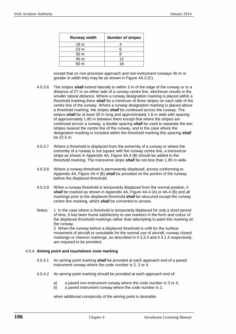
Irish Aviation Authority January 2014
106 Chapter 4 Aerodrome Licensing Manual
Runway width Number of stripes
18 m 4
23 m 6
30 m 8
45 m 12
60 m 16
except that on non-precision approach and non-instrument runways 45 m or greater in width they may be as shown in Figure 4A.3 (C).
4.5.3.6 The stripes shall extend laterally to within 3 m of the edge of the runway or to a
distance of 27 m on either side of a runway centre line, whichever results in the smaller lateral distance. Where a runway designation marking is placed within a threshold marking there shall be a minimum of three stripes on each side of the centre line of the runway. Where a runway designation marking is placed above a threshold marking, the stripes shall be continued across the runway. The stripes shall be at least 30 m long and approximately 1.8 m wide with spacing of approximately 1.80 m between them except that where the stripes are continued across a runway, a double spacing shall be used to separate the two stripes nearest the centre line of the runway, and in the case where the designation marking is included within the threshold marking this spacing shall be 22.5 m.
4.5.3.7 Where a threshold is displaced from the extremity of a runway or where the
extremity of a runway is not square with the runway centre line, a transverse stripe as shown in Appendix 4A, Figure 4A.4 (B) should be added to the threshold marking. The transverse stripe shall be not less than 1.80 m wide.
4.5.3.8 Where a runway threshold is permanently displaced, arrows conforming to
Appendix 4A, Figure 4A.4 (B) shall be provided on the portion of the runway before the displaced threshold.
4.5.3.9 When a runway threshold is temporarily displaced from the normal position, it
shall be marked as shown in Appendix 4A, Figure 4A.4 (A) or 4A.4 (B) and all markings prior to the displaced threshold shall be obscured except the runway centre line marking, which shall be converted to arrows.
Notes: 1 In the case where a threshold is temporarily displaced for only a short period
of time, it has been found satisfactory to use markers in the form and colour of the displaced threshold markings rather than attempting to paint this marking on the runway.
2 When the runway before a displaced threshold is unfit for the surface movement of aircraft or unsuitable for the normal use of aircraft, runway closed markings or chevron markings, as described in 4.3.3.3 and 4.3.1.4 respectively, are required to be provided.
4.5.4 Aiming point and touchdown zone marking
4.5.4.1 An aiming point marking shall be provided at each approach end of a paved instrument runway where the code number is 2, 3 or 4.
4.5.4.2 An aiming point marking should be provided at each approach end of:
a) a paved non-instrument runway where the code number is 3 or 4; b) a paved instrument runway where the code number is 1,
when additional conspicuity of the aiming point is desirable.
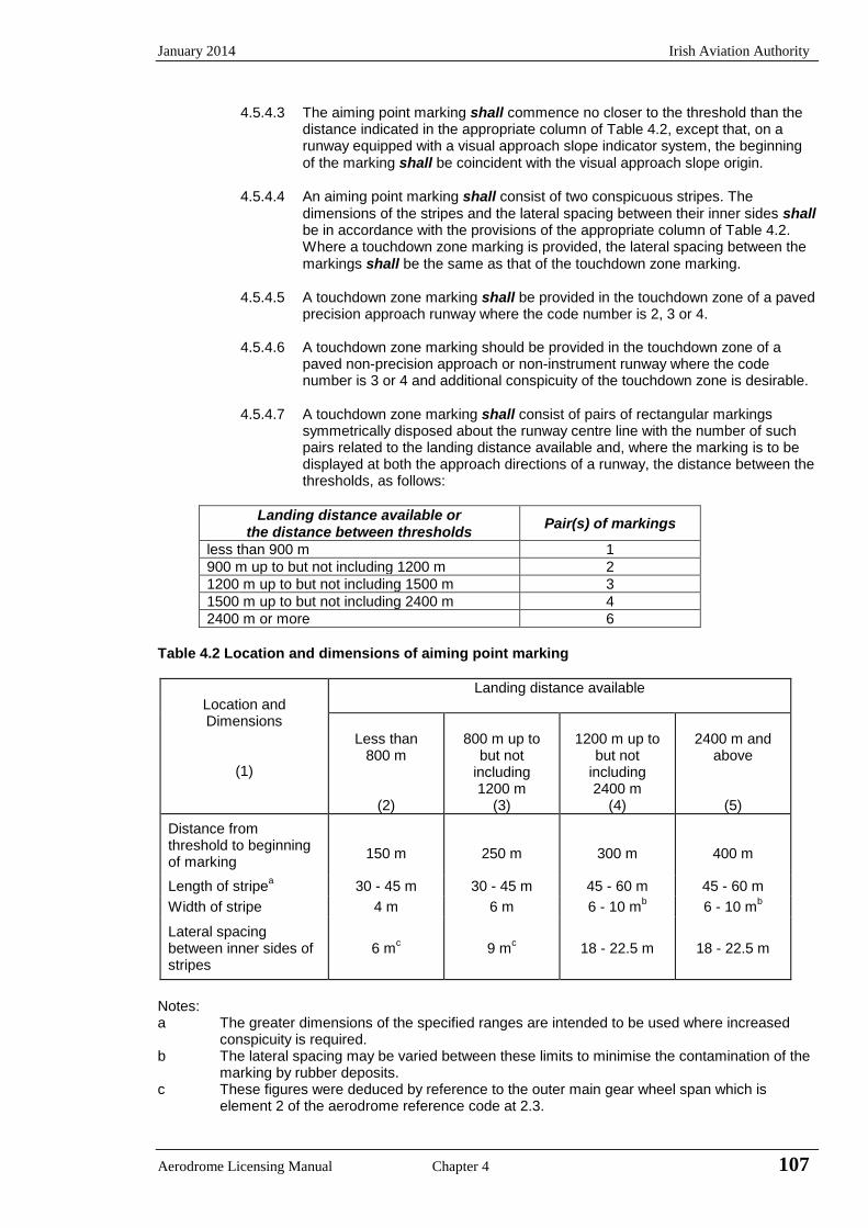
January 2014 Irish Aviation Authority
Aerodrome Licensing Manual Chapter 4 107
4.5.4.3 The aiming point marking shall commence no closer to the threshold than the distance indicated in the appropriate column of Table 4.2, except that, on a runway equipped with a visual approach slope indicator system, the beginning of the marking shall be coincident with the visual approach slope origin.
4.5.4.4 An aiming point marking shall consist of two conspicuous stripes. The
dimensions of the stripes and the lateral spacing between their inner sides shall be in accordance with the provisions of the appropriate column of Table 4.2. Where a touchdown zone marking is provided, the lateral spacing between the markings shall be the same as that of the touchdown zone marking.
4.5.4.5 A touchdown zone marking shall be provided in the touchdown zone of a paved
precision approach runway where the code number is 2, 3 or 4.
4.5.4.6 A touchdown zone marking should be provided in the touchdown zone of a paved non-precision approach or non-instrument runway where the code number is 3 or 4 and additional conspicuity of the touchdown zone is desirable.
4.5.4.7 A touchdown zone marking shall consist of pairs of rectangular markings
symmetrically disposed about the runway centre line with the number of such pairs related to the landing distance available and, where the marking is to be displayed at both the approach directions of a runway, the distance between the thresholds, as follows:
Landing distance available or the distance between thresholds
Pair(s) of markings
less than 900 m 1
900 m up to but not including 1200 m 2
1200 m up to but not including 1500 m 3
1500 m up to but not including 2400 m 4
2400 m or more 6
Table 4.2 Location and dimensions of aiming point marking
Location and Dimensions
(1)
Landing distance available
Less than
800 m
(2)
800 m up to
but not including 1200 m
(3)
1200 m up to
but not including 2400 m
(4)
2400 m and
above
(5)
Distance from threshold to beginning of marking
150 m
250 m
300 m
400 m
Length of stripea 30 - 45 m 30 - 45 m 45 - 60 m 45 - 60 m
Width of stripe 4 m 6 m 6 - 10 mb 6 - 10 m
b
Lateral spacing between inner sides of stripes
6 mc 9 m
c 18 - 22.5 m 18 - 22.5 m
Notes: a The greater dimensions of the specified ranges are intended to be used where increased
conspicuity is required. b The lateral spacing may be varied between these limits to minimise the contamination of the
marking by rubber deposits. c These figures were deduced by reference to the outer main gear wheel span which is
element 2 of the aerodrome reference code at 2.3.
Irish Aviation Authority January 2014
108 Chapter 4 Aerodrome Licensing Manual
4.5.4.8 The touchdown zone marking shall conform to either of the two patterns shown
in Appendix 4A, Figure 4A.6. For the pattern shown in Figure 4A.6 A the markings shall be not less than 22.5 m long and 3 m wide. For the pattern shown in Figure 4A.6 B each stripe of each marking shall be not less than 22.5 m long and 1.8 m wide with a spacing of 1.5 m between adjacent stripes. The lateral spacing between the inner sides of the rectangles shall be equal to that of the aiming point marking where provided. Where an aiming point marking is not provided, the lateral spacing between the inner sides of the rectangles shall correspond to the lateral spacing specified for the aiming point marking in Table 4.2 (columns 2, 3, 4 or 5 as appropriate). The pairs of markings shall be provided at longitudinal spacing of 150 m beginning from the threshold except that pairs of touchdown zone markings coincident with or located within 50 m of the aiming point marking shall be deleted from the pattern.
4.5.4.9 On a non-precision approach runway where the code number is 2 an additional
pair of touchdown zone marking stripes should be provided 150 m beyond the beginning of the aiming point marking.
4.5.5 Runway side stripe marking
4.5.5.1 A runway side stripe marking shall be provided between the thresholds of a paved runway where there is a lack of contrast between the runway edges and the shoulders or the surrounding terrain.
4.5.5.2 A runway side stripe marking should be provided on a precision approach
runway irrespective of the contrast between the runway edges and the shoulders or the surrounding terrain.
4.5.5.3 A runway side stripe marking should consist of two stripes, one placed along
each edge of the runway with the outer edge of each stripe approximately on the edge of the runway, except that, where the runway is greater than 60 m in width, the stripes should be located 30 m from the runway centre line.
4.5.5.4 Where a runway turn pad is provided, the runway side stripe marking should be
continued between the runway and the runway turn pad.
4.5.5.5 A runway side stripe should have an overall width of at least 0.9 m on runways 30m or more in width and at least 0.45 m on narrower runways.
4.5.6 Markings on unpaved runways and taxiways
4.5.6.1 According to the requirements herein relating specifically to unpaved runways and taxiways the following should be provided at far as practicable:
a) a threshold marking (4.5.3); b) a runway designation marking at the threshold (4.5.1); c) taxiway markings as prescribed for a paved taxiway.
4.5.6.2 When the extent of an unpaved runway, stopway or taxiway is not clearly
indicated by the appearance of the surface compared with that of the surrounding ground, markers in accordance with the requirements in paragraphs 4.8.2, 4.8.3 and 4.8.7 should be provided.
4.5.6.3 Areas on runways and taxiways that are permanently or temporarily closed to
the use of all aircraft or are unfit for the movement of aircraft should be marked as specified in Section 4.3.
4.5.6.4 Taking into account the physical characteristics of the aerodrome, the type of
aircraft using it, the nature of operations and practical difficulties the Authority will specify the markings/markers required.

January 2014 Irish Aviation Authority
Aerodrome Licensing Manual Chapter 4 109
4.6 Taxiway and Other Markings
4.6.1 Taxiway centre line markings
4.6.1.1 Taxiway centre line marking shall be provided on a paved taxiway, de/anti-icing facility and apron where the code number is 3 or 4 in such a way as to provide continuous guidance between the runway centre line and aircraft stands.
4.6.1.2 Taxiway centre line marking should be provided on a paved taxiway, de/anti-
icing facility and apron where the code number is 1 or 2 in such a way as to provide continuous guidance between the runway centre line and the aircraft stands.
4.6.1.3 Taxiway centre line marking shall be provided on a paved runway when the
runway is part of a standard taxi-route and:
a) there is no runway centre line marking; or b) where the taxiway centre line is not coincident with the runway centreline.
4.6.1.4 Where it is necessary to denote the proximity of a runway-holding position, enhanced taxiway centre line marking should be provided.
Note The provision of enhanced taxiway centre line marking may form part of runway
incursion measures.
4.6.1.5 Where provided, enhanced taxiway centre line marking shall be installed at all taxiway/runway intersections at that aerodrome.
4.6.1.6 On a straight section of a taxiway the taxiway centre line marking should be
located along the taxiway centre line. On a taxiway curve the marking should continue from the straight portion of the taxiway at a constant distance from the outside edge of the curve.
4.6.1.7 At an intersection of a taxiway with a runway where the taxiway serves as an
exit from the runway, the taxiway centre line markings should be curved into the runway centre line marking as shown in Appendix 4A Figure 4A.7. The taxiway centre line marking should be extended parallel to the runway centre line marking for a distance of at least 60 m beyond the point of tangency where the code number is 3 or 4, and for a distance of at least 30 m when the code number is 1 or 2.
4.6.1.8 Where taxiway centre line marking is provided on a runway in accordance with
paragraph 4.6.1.3, the marking should be located on the centre line of the designated taxiway.
4.6.1.9 Where provided, an enhanced taxiway centre line marking shall extend from the
runway holding position Pattern A (as defined in Appendix 4A, Figure 4A.7, taxiway markings) to a distance of up to 47m (a minimum of three (3) dashed lines) in the direction of travel away from the runway or to the next runway holding position, if within 47m distance.
4.6.1.10 A taxiway centre line marking shall be at least 15 cm in width and continuous in
length except where it intersects with a runway-holding position marking or an intermediate holding position marking as shown in Appendix 4A, Fig. 4A.7.
4.6.1.11 Enhanced taxiway centre line marking shall be as shown in Appendix 4A, Fig.
4A.8.
Irish Aviation Authority January 2014
110 Chapter 4 Aerodrome Licensing Manual
4.6.2 Runway Turn Pad Markings
4.6.2.1 Where a runway pad is provided, a runway turn pad marking shall be provided
for continuous guidance to enable an aeroplane to complete a 180-degree turn and align with the runway centre line.
4.6.2.2 The runway turn pad marking should be curved from the runway centreline into
the turn pad. The radius of the curve should be compatible with the manoeuvring capability and normal taxiing speeds of the aeroplane for which the runway turn pad is intended. The intersection angle of the runway turn pad marking with the runway centre line should not be greater than 30 degrees.
4.6.2.3 The runway turn pad marking should be extended parallel to the runway centre
line marking for a distance of at least 60 m beyond the point of the tangency where the code number is three or four, and for a distance of at least 30 m where the code number is 1 or 2.
4.6.2.4 A runway turn pad marking should guide the aeroplane in such a way as to
allow a straight portion of taxiing before the point where a 180-degree turn is to be made. The straight portion of the runway turn pad marking should be parallel to the outer edge of the runway turn pad.
4.6.2.5 The design of the curve allowing the aeroplane to negotiate a 180-degree turn
should be based on a nose wheel steering angle not exceeding 45 degrees.
4.6.2.6 The design of the turn pad marking should be such that, when the cockpit of the aeroplane remains over the runway turn pad marking, the clearance distance between any wheel of the aeroplane landing gear and the edge of the runway turn pad should be not less than those specified in 2.4.13.6.
Note – For ease of manoeuvring, consideration may be given to providing a larger wheel-to-edge clearance for codes E and F aeroplanes (See 2.4.13.7).
4.6.2.7 A runway turn pad marking shall be at least 15 cm in width and continuous in
length.
4.6.3 Runway-holding position marking
4.6.3.1 A runway-holding position marking shall be displayed along a runway-holding position.
Note: See Section 4.7.2 concerning the provisions of signs at a runway-holding
position.
4.6.3.2 At an intersection of a taxiway and a non-instrument, non-precision approach, or take-off runway, the runway-holding-position marking shall be as shown in Appendix 4A, Figure 4A.7, pattern A.
4.6.3.3 Where a single runway-holding position is provided at an intersection of a
taxiway and a precision approach category I, II or III runway, the runway-holding position marking shall be as shown in Appendix 4A, Figure 4A.7, pattern A. Where two or three runway-holding positions are provided at such an intersection the runway-holding position marking closer (closest) to the runway shall be as shown Figure 4A.7, pattern A and the markings farther from the runway shall be as shown in Figure 4A.7, pattern B.
4.6.3.4 The runway-holding position marking displayed at a runway-holding position
established in accordance with paragraph 2.5.11.3 shall be as shown in Appendix 4A, Figure 4A.7, Pattern A.
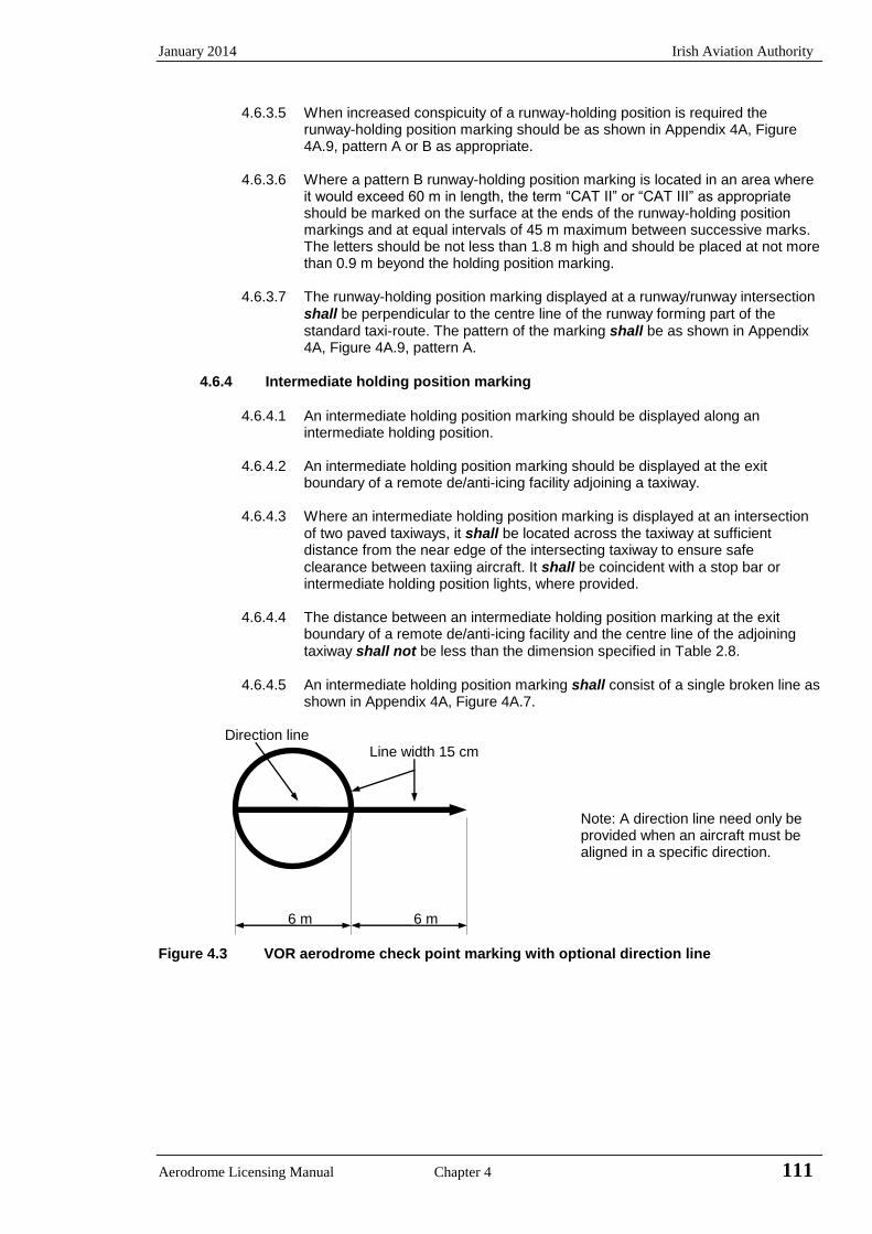
January 2014 Irish Aviation Authority
Aerodrome Licensing Manual Chapter 4 111
4.6.3.5 When increased conspicuity of a runway-holding position is required the runway-holding position marking should be as shown in Appendix 4A, Figure 4A.9, pattern A or B as appropriate.
4.6.3.6 Where a pattern B runway-holding position marking is located in an area where
it would exceed 60 m in length, the term “CAT II” or “CAT III” as appropriate should be marked on the surface at the ends of the runway-holding position markings and at equal intervals of 45 m maximum between successive marks. The letters should be not less than 1.8 m high and should be placed at not more than 0.9 m beyond the holding position marking.
4.6.3.7 The runway-holding position marking displayed at a runway/runway intersection
shall be perpendicular to the centre line of the runway forming part of the standard taxi-route. The pattern of the marking shall be as shown in Appendix 4A, Figure 4A.9, pattern A.
4.6.4 Intermediate holding position marking
4.6.4.1 An intermediate holding position marking should be displayed along an
intermediate holding position. 4.6.4.2 An intermediate holding position marking should be displayed at the exit
boundary of a remote de/anti-icing facility adjoining a taxiway.
4.6.4.3 Where an intermediate holding position marking is displayed at an intersection of two paved taxiways, it shall be located across the taxiway at sufficient distance from the near edge of the intersecting taxiway to ensure safe clearance between taxiing aircraft. It shall be coincident with a stop bar or intermediate holding position lights, where provided.
4.6.4.4 The distance between an intermediate holding position marking at the exit
boundary of a remote de/anti-icing facility and the centre line of the adjoining taxiway shall not be less than the dimension specified in Table 2.8.
4.6.4.5 An intermediate holding position marking shall consist of a single broken line as
shown in Appendix 4A, Figure 4A.7. Direction line Line width 15 cm
Note: A direction line need only be provided when an aircraft must be aligned in a specific direction.
6 m 6 m
Figure 4.3 VOR aerodrome check point marking with optional direction line

Irish Aviation Authority January 2014
112 Chapter 4 Aerodrome Licensing Manual
4.6.5 VOR aerodrome check-point marking
4.6.5.1 When a VOR aerodrome check-point is established it shall be indicated by a VOR aerodrome check-point marking and sign.
Notes: 1 See 4.7.4 for VOR aerodrome check-point sign. 2 Guidance on the selection of sites for VOR aerodrome check-points is given
in Annex 10, volume 1.
4.6.5.2 A VOR aerodrome check-point marking shall be centred on the spot at which an aircraft is to be parked to receive the correct VOR signal.
4.6.5.3 A VOR aerodrome check-point marking shall consist of a circle 6 m in diameter
and have a line width of 15 cm.(See Figure 4.2)
4.6.5.4 When it is preferable for an aircraft to be aligned in a specific direction, a line should be provided that passes through the centre of the circle on the desired azimuth. The line should extend 6 m outside the circle in the desired direction of heading and terminate in an arrowhead. The width of the line should be 15 cm. (See Figure 4.3).
4.6.5.5 A VOR aerodrome check-point marking should preferably be white in colour but
should differ from the colour used for the taxiway markings.
Note: To provide contrast marking may be bordered with black.
4.6.6 Aircraft stand markings
Note: Guidance on the layout of aircraft stand markings is contained in Aerodrome
Design Manual, Part 4 (Doc 9157).
4.6.6.1 Aircraft stand markings should be provided for designated parking positions on a paved apron; and on a de/anti-icing facility.
4.6.6.2 Aircraft stand markings on a paved apron and on a de/anti-icing facility should
be located so as to provide the clearances specified in 2.6.5.1 and 2.6.8.1 respectively when the nose wheel follows the stand marking.
4.6.6.3 Aircraft stand markings should include such elements as stand identification,
lead-in line, turn bar, turning line, alignment bar, stop line and lead-out line, as are required by the parking configuration and to complement other parking aids.
4.6.6.4 An aircraft stand identification (letter and/or number) should be included in the
lead-in line a short distance after the beginning of the lead-in line. The height of the identification should be adequate to be readable from the cockpit of aircraft using the stand.
4.6.6.5 Where two sets of aircraft stand markings are superimposed on each other in
order to permit more flexible use of the apron and it is difficult to identify which stand marking should be followed, or safety would be impaired if the wrong marking was followed then identification of the aircraft for which each set of markings is intended should be added to the stand identification.
Note: Example: 2A - B747, 2B - F28.
4.6.6.6 Lead-in, turning and lead-out lines should normally be continuous in length and
have a width of not less than 15 cm. Where one or more sets of stand markings are superimposed on a stand marking, the lines should be continuous for the most demanding aircraft and broken for other aircraft.
January 2014 Irish Aviation Authority
Aerodrome Licensing Manual Chapter 4 113
4.6.6.7 The curved portions of lead-in, turning and lead-out lines should have radii appropriate to the most demanding aircraft type for which the markings are intended.
4.6.6.8 Where it is intended that an aircraft proceed in one direction only, arrows
pointing in the direction to be followed should be added as part of the lead-in and lead-out lines.
4.6.6.9 A turn bar should be located at right angles to the lead-in line, abeam the left
pilot position at the point of initiation of any intended turn. It should have a length and width of not less than 6 m and 15 cm respectively and include an arrowhead to indicate the direction of turn.
Note The distances to be maintained between the turn bar and the lead-in line may
vary according to different aircraft types, taking into account the pilot’s field of view.
4.6.6.10 If more than one turn bar and/or stop line is required they should be coded.
4.6.6.11 An alignment bar should be placed so as to be coincident with the extended
centre line of the aircraft for the specified parking position and visible to the pilot during the final part of the parking manoeuvre. It should have a width not less than 15 cm.
4.6.6.12 A stop line should be located at right angles to the alignment bar abeam the left
pilot position at the intended point of stop. It should have a length and width of not less than 6 m and 15 cm, respectively.
Note The distances to be maintained between the stop line and the lead-in line vary
according to different aircraft types, taking into account the pilot’s field of view.
4.6.7 Apron safety lines
Note: Guidance on apron safety lines is contained in the Aerodrome Design Manual,
Part 4 (Doc 9157).
4.6.7.1 Apron safety lines should be provided on a paved apron as required by the
parking configurations and ground facilities.
4.6.7.2 Apron safety lines shall be located so as to define the areas intended for use by ground vehicles and other aircraft servicing equipment, etc., to provide safe separation from aircraft.
4.6.7.3 Apron safety lines should include such elements as wing tip clearance lines and
service road boundary lines as required by the parking configurations and ground facilities.
4.6.7.4 An apron safety line should be continuous in length and at least 10 cm in width.
4.6.8 Road-holding position marking
4.6.8.1 A road-holding position marking shall be provided at all road entrances to a runway.
4.6.8.2 The road-holding position marking shall be located across the road at the
holding position.
4.6.8.3 The road-holding position marking shall be in accordance with the local road traffic regulations.
Irish Aviation Authority January 2014
114 Chapter 4 Aerodrome Licensing Manual
4.6.9 Mandatory instruction marking
Note Guidance on mandatory instruction marking is given in the Aerodrome Design
Manual, Part 4 (Doc 9157)
4.6.9.1 Where it is impracticable to install a mandatory instruction sign in accordance
with paragraph 4.7.2.1 a mandatory instruction marking shall be provided on the surface of the pavement.
4.6.9.2 Where operationally required such as on taxiways exceeding 60 m in width, or
to assist in the prevention of a runway incursion, a mandatory instruction sign should be supplemented by a mandatory instruction marking.
4.6.9.3 The mandatory instruction marking on taxiways, where the code letter is A, B, C
or D, shall be located across the taxiway equally placed about the taxiway centreline and on the holding side of the runway-holding position marking as shown in Appendix 4A, Fig 4A.10 (a). The distance between the nearest edge of the marking and the runway holding position marking or the taxiway centreline marking shall be not less than 1 m.
4.6.9.4 The mandatory instruction marking on taxiways, where the code letter is E or F,
shall be located on both sides of the taxiway centre line marking and on the holding side of the runway-holding position marking as shown in Appendix 4A, Figure 4A.10 (b). The distance between the nearest edge of the marking and the runway-holding position marking or the taxiway centre line marking shall be not less than 1 m.
4.6.9.5 Except where operationally required, a mandatory instruction marking should
not be located on a runway.
4.6.9.6 A mandatory instruction marking shall consist of an inscription in white on a red background. Except for a NO ENTRY marking the inscription shall provide information identical to that of the associated mandatory instruction sign.
4.6.9.7 A NO ENTRY marking shall consist of an inscription in white reading NO
ENTRY on a red background.
4.6.9.8 Where there is insufficient contrast between the marking and the pavement surface, the mandatory instruction marking shall include an appropriate border, preferably white or black.
4.6.9.9 The character height should be 4 m for inscriptions where the code letter is C,
D, E or F and 2 m where the code letter is A or B. The inscriptions should be in the form and proportions shown in Appendix 4B.
4.6.9.10 The background should be rectangular and extend to a minimum of 0.5 m
laterally and vertically beyond the extremities of the inscription.
4.6.10 Information marking
Note: Guidance on information marking is contained in the Aerodrome Design
Manual, Part 4 (Doc 9157).
4.6.10.1 Where an information sign would normally be installed and it is impractical to
install, as determined by the appropriate authority, an information marking shall be displayed on the surface of the pavement.
4.6.10.2 Where operationally required an information sign should be supplemented by
an information marking.
January 2014 Irish Aviation Authority
Aerodrome Licensing Manual Chapter 4 115
4.6.10.3 An information (location/direction) marking should be displayed prior to and following complex taxiway intersections and where operational experience has indicated the addition of a taxiway location marking could assist flight crew ground navigation.
4.6.10.4 An information (location) marking should be displayed on the pavement surface at regular intervals along taxiways of great length.
4.6.10.5 The information marking should be displayed across the surface of the taxiway or apron where necessary and positioned so as to be legible from the cockpit of an approaching aircraft.
4.6.10.6 An information marking shall consist of
a) an inscription in yellow, upon a black background, when it replaces orsupplements a location sign; and
b) an inscription in black upon a yellow background, when it replaces orsupplements a direction or destination sign.
4.6.10.7 Where there is insufficient contrast between the marking and the pavement surface, the marking shall include:
a) a black border where the inscriptions are in black; andb) a yellow border where the inscriptions are in yellow.
4.6.10.8 The character height should be 4 m. The inscriptions should be in the form and proportions shown in Appendix 4B.
4.7 Signs
Note: Signs shall be either fixed message signs or variable message signs. Guidance on signs is contained in the Aerodrome Design Manual, Part 4 (Doc 9157).
4.7.1 General
4.7.1.1 Signs shall be provided to convey a mandatory instruction, information on a specific location or destination on a movement area or to provide other information to meet the requirements of 7.11.4.
Note See 4.6.10 for specifications on mandatory instruction and information marking.
4.7.1.2 A variable message sign should be provided where:
a) the instruction or information displayed on the sign is relevant onlyduring a certain period of time; and/or
b) there is a need for variable pre-determined information to bedisplayed on the sign to meet the requirements of 7.11.4.
4.7.1.3 Signs shall be frangible. Those located near a runway or taxiway shall be sufficiently low to preserve clearance for propellers and the engine pods of jet aircraft. The installed height of the sign shall not exceed the dimension shown in the appropriate column of Table 4.3.
4.7.1.4 Signs shall be rectangular as shown in Appendix 4A, Figures 4A.11 and 4A.12 with the longer side horizontal.
4.7.1.5 The only signs on the movement area utilising red shall be mandatory instruction signs.
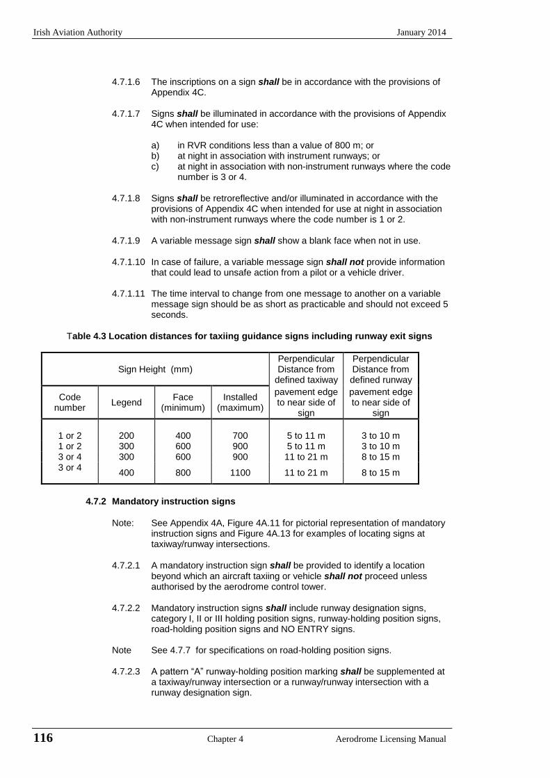
Irish Aviation Authority January 2014
116 Chapter 4 Aerodrome Licensing Manual
4.7.1.6 The inscriptions on a sign shall be in accordance with the provisions of
Appendix 4C.
4.7.1.7 Signs shall be illuminated in accordance with the provisions of Appendix 4C when intended for use:
a) in RVR conditions less than a value of 800 m; or b) at night in association with instrument runways; or c) at night in association with non-instrument runways where the code
number is 3 or 4.
4.7.1.8 Signs shall be retroreflective and/or illuminated in accordance with the provisions of Appendix 4C when intended for use at night in association with non-instrument runways where the code number is 1 or 2.
4.7.1.9 A variable message sign shall show a blank face when not in use.
4.7.1.10 In case of failure, a variable message sign shall not provide information
that could lead to unsafe action from a pilot or a vehicle driver.
4.7.1.11 The time interval to change from one message to another on a variable message sign should be as short as practicable and should not exceed 5 seconds.
Table 4.3 Location distances for taxiing guidance signs including runway exit signs
Sign Height (mm)
Perpendicular Distance from
defined taxiway
Perpendicular Distance from defined runway
Code number
Legend Face
(minimum) Installed
(maximum)
pavement edge to near side of
sign
pavement edge to near side of
sign
1 or 2
200
400
700
5 to 11 m
3 to 10 m
1 or 2 300 600 900 5 to 11 m 3 to 10 m 3 or 4 300 600 900 11 to 21 m 8 to 15 m 3 or 4
400 800 1100 11 to 21 m 8 to 15 m
4.7.2 Mandatory instruction signs
Note: See Appendix 4A, Figure 4A.11 for pictorial representation of mandatory
instruction signs and Figure 4A.13 for examples of locating signs at taxiway/runway intersections.
4.7.2.1 A mandatory instruction sign shall be provided to identify a location
beyond which an aircraft taxiing or vehicle shall not proceed unless authorised by the aerodrome control tower.
4.7.2.2 Mandatory instruction signs shall include runway designation signs,
category I, II or III holding position signs, runway-holding position signs, road-holding position signs and NO ENTRY signs.
Note See 4.7.7 for specifications on road-holding position signs.
4.7.2.3 A pattern “A” runway-holding position marking shall be supplemented at
a taxiway/runway intersection or a runway/runway intersection with a runway designation sign.
January 2014 Irish Aviation Authority
Aerodrome Licensing Manual Chapter 4 117
4.7.2.4 A pattern “B” runway-holding position marking shall be supplemented with a category I, II or III holding position sign.
4.7.2.5 A pattern “A” runway-holding position marking at a runway-holding position established in accordance with 2.5.11.3 shall be supplemented with a runway-holding position sign.
Note See 4.6.3 for specifications on runway-holding position marking.
4.7.2.6 A runway designation sign at a taxiway/runway intersection should be supplemented with a location sign on the outboard (farthest from the taxiway) position, as appropriate.
Note See 4.7.3 for characteristics of location signs.
4.7.2.7 A NO ENTRY sign shall be provided when entry into an area is prohibited.
4.7.2.8 A runway designation sign at a taxiway/runway intersection or a
runway/runway intersection shall be located on each side of the runway-holding position marking facing the direction of approach to the runway.
4.7.2.9 A category I, II or III holding position sign shall be located on each side of
the runway-holding position marking facing the direction of the approach to the critical area.
4.7.2.10 A NO ENTRY sign shall be located at the beginning of the area to which
entrance is prohibited on each side of the taxiway as viewed by the pilot.
4.7.2.11 A runway-holding position sign shall be located on each side of the runway-holding position established in accordance with 2.5.11.3, facing the approach to the obstacle limitation surface or ILS/MLS critical/sensitive area, as appropriate.
4.7.2.12 A mandatory instruction sign shall consist of an inscription in white on a
red background.
4.7.2.13 Where, owing to environmental or other factors, the conspicuity of the inscription on a mandatory instruction sign needs to be enhanced, the outside edge of the white inscription should be supplemented by a black outline measuring 10mm in width for runway code numbers 1 and 2, and 20mm in width for runway code numbers 3 and 4.
4.7.2.14 The inscription on a runway designation sign shall consist of the runway
designations of the intersecting runway properly oriented with respect to the viewing position of the sign, except that a runway designation sign installed in the vicinity of a runway extremity may show the runway designation of the concerned runway extremity only.
4.7.2.15 The inscription on a category I, II, III or joint II/III holding position sign
shall consist of the runway designator followed by CAT I, CAT II, CAT III or CAT II/III, as appropriate.
4.7.2.16 The inscription on a NO ENTRY sign shall be in accordance with
Appendix 4A, Figure 4A.11.
4.7.2.17 The inscription on a runway-holding position sign at a runway-holding position established in accordance with 2.5.11.3 shall consist of the taxiway designation and a number.
4.7.2.18 Where appropriate, the following inscriptions/symbol shall be used:
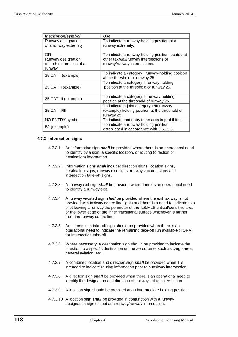
Irish Aviation Authority January 2014
118 Chapter 4 Aerodrome Licensing Manual
Inscription/symbol Use
Runway designation of a runway extremity OR Runway designation of both extremities of a runway.
To indicate a runway-holding position at a runway extremity. To indicate a runway-holding position located at other taxiway/runway intersections or runway/runway intersections.
25 CAT I (example) To indicate a category I runway-holding position at the threshold of runway 25.
25 CAT II (example) To indicate a category II runway-holding position at the threshold of runway 25.
25 CAT III (example) To indicate a category III runway-holding position at the threshold of runway 25.
25 CAT II/III
To indicate a joint category II/III runway-(example) holding position at the threshold of runway 25.
NO ENTRY symbol To indicate that entry to an area is prohibited.
B2 (example) To indicate a runway-holding position established in accordance with 2.5.11.3.
4.7.3 Information signs
4.7.3.1 An information sign shall be provided where there is an operational need to identify by a sign, a specific location, or routing (direction or destination) information.
4.7.3.2 Information signs shall include: direction signs, location signs,
destination signs, runway exit signs, runway vacated signs and intersection take-off signs.
4.7.3.3 A runway exit sign shall be provided where there is an operational need
to identify a runway exit.
4.7.3.4 A runway vacated sign shall be provided where the exit taxiway is not provided with taxiway centre line lights and there is a need to indicate to a pilot leaving a runway the perimeter of the ILS/MLS critical/sensitive area or the lower edge of the inner transitional surface whichever is farther from the runway centre line.
4.7.3.5 An intersection take-off sign should be provided when there is an
operational need to indicate the remaining take-off run available (TORA) for intersection take-off.
4.7.3.6 Where necessary, a destination sign should be provided to indicate the
direction to a specific destination on the aerodrome, such as cargo area, general aviation, etc.
4.7.3.7 A combined location and direction sign shall be provided when it is
intended to indicate routing information prior to a taxiway intersection.
4.7.3.8 A direction sign shall be provided when there is an operational need to identify the designation and direction of taxiways at an intersection.
4.7.3.9 A location sign should be provided at an intermediate holding position.
4.7.3.10 A location sign shall be provided in conjunction with a runway
designation sign except at a runway/runway intersection.
January 2014 Irish Aviation Authority
Aerodrome Licensing Manual Chapter 4 119
4.7.3.11 A location sign shall be provided in conjunction with a direction sign,
except that it may be omitted where an aeronautical study indicates that it is not needed.
4.7.3.12 Where necessary, a location sign should be provided to identify taxiways
exiting an apron or taxiways beyond an intersection.
4.7.3.13 Where a taxiway ends at an intersection such as a “T” and it is necessary to identify this, a barricade, direction sign and/or other appropriate visual aid should be used.
4.7.3.14 Except as specified in 4.7.3.16 and 4.7.3.24 information signs shall,
wherever practicable, be located on the left-hand side of the taxiway in accordance with Table 4.3.
4.7.3.15 At a taxiway intersection, information signs shall be located prior to the
intersection and in line with the taxiway intersection marking. Where there is no taxiway intersection marking, the signs shall be installed at least 60m from the centre line of the intersecting taxiway where the code number is 3 or 4 and at least 40m where the code number is 1 or 2.
Note: A location sign installed beyond a taxiway intersection may be installed
on either side of a taxiway.
4.7.3.16 A runway exit sign shall be located on the same side of the runway as the exit is located (i.e. left or right) and positioned in accordance with Table 4.3.
4.7.3.17 A runway exit sign shall be located prior to the runway exit point in line
with a position at least 60m prior to the point of tangency where the code number is 3 or 4, and at least 30m where the code number is 1 or 2.
4.7.3.18 A runway vacated sign shall be located at least on one side of the
taxiway. The distance between the sign and the centre line of the runway shall be no less than the greater of the following: a) the distance between the centre line of the runway and the
perimeter of the ILS/MLS critical/sensitive area; or b) the distance between the centre line of the runway and the lower
edge of the inner transitional surface.
4.7.3.19 Where provided in conjunction with a runway vacated sign, the taxiway location sign shall be positioned outboard of the runway vacated sign.
4.7.3.20 An intersection take-off sign shall be located at the left-hand side of the
entry taxiway. The distance between the sign and the centre line of the runway shall not be less than 60 m where the code number is 3 or 4, and not less than 45 m where the code number is 1 or 2.
4.7.3.21 A taxiway location sign installed in conjunction with a runway designation
sign shall be placed outboard of the runway designation sign.
4.7.3.22 A destination sign should not normally be collocated with a location or direction sign.
4.7.3.23 An information sign other than a location sign shall not be collocated
with a mandatory instruction sign. 4.7.3.24 A direction sign, barricade and/or other appropriate visual aid used to
identify a “T” intersection should be located on the opposite side of the
Irish Aviation Authority January 2014
120 Chapter 4 Aerodrome Licensing Manual
intersection facing the taxiway.
4.7.3.25 An information sign other than a location sign shall consist of an inscription in black on a yellow background.
4.7.3.26 A location sign shall consist of an inscription in yellow on a black
background and where it is a stand-alone sign shall have a yellow border.
4.7.3.27 The inscription on a runway exit sign shall consist of the designator of the exit taxiway and an arrow indicating the direction to follow.
4.7.3.28 The inscription on a runway vacated sign shall depict the pattern A
runway-holding position marking as shown in Appendix 4A, Figure 4A.12.
4.7.3.29 The inscription on an intersection take-off sign shall consist of a numerical message indicating the remaining take-off run available in metres plus an arrow, appropriately located and oriented, indicating the direction of take-off as shown in Appendix 4A, Figure 4A.12.
4.7.3.30 The inscription on a destination sign shall comprise an alpha,
alphanumerical or numerical message identifying the destination plus an arrow indicating the direction to proceed as shown in Appendix 4A, Figure 4A.12.
4.7.3.31 The inscription on a direction sign shall comprise an alpha, or
alphanumerical message identifying the destination plus an arrow, or arrows, appropriately located and oriented indicating the direction of the take-off as shown in Appendix 4A, Figure 4A.12.
4.7.3.32 The inscription on a location sign shall comprise the designation of the
location taxiway, runway or other pavement the aircraft is on or is entering and shall not contain arrows.
4.7.3.33 Where it is necessary to identify each of a series of intermediate holding
positions on the same taxiway, the location sign should consist of the taxiway designation and a number.
4.7.3.34 Where a location sign and direction signs are used in combination:
a) all direction signs related to left turns shall be placed on the left
side of the location sign and all direction signs related to right turns shall be placed on the right side of the location sign, except that where the junction consists of one intersecting taxiway, the location sign may alternatively be placed on the left-hand side;
b) the direction signs shall be placed such that the direction of the
arrows departs increasingly from the vertical with increasing deviation of the corresponding taxiway;
c) an appropriate direction sign shall be placed next to the location
sign where the direction of the location taxiway changes significantly beyond the intersection; and
d) adjacent direction signs shall be delineated by a vertical black line
as shown in Appendix 4A, Figure 4A.12. 4.7.3.35 A taxiway shall be identified by a designator comprising a letter, letters or
a combination of a letter or letters followed by a number.
4.7.3.36 When designating taxiways, the use of the letters I, O or X and the use of
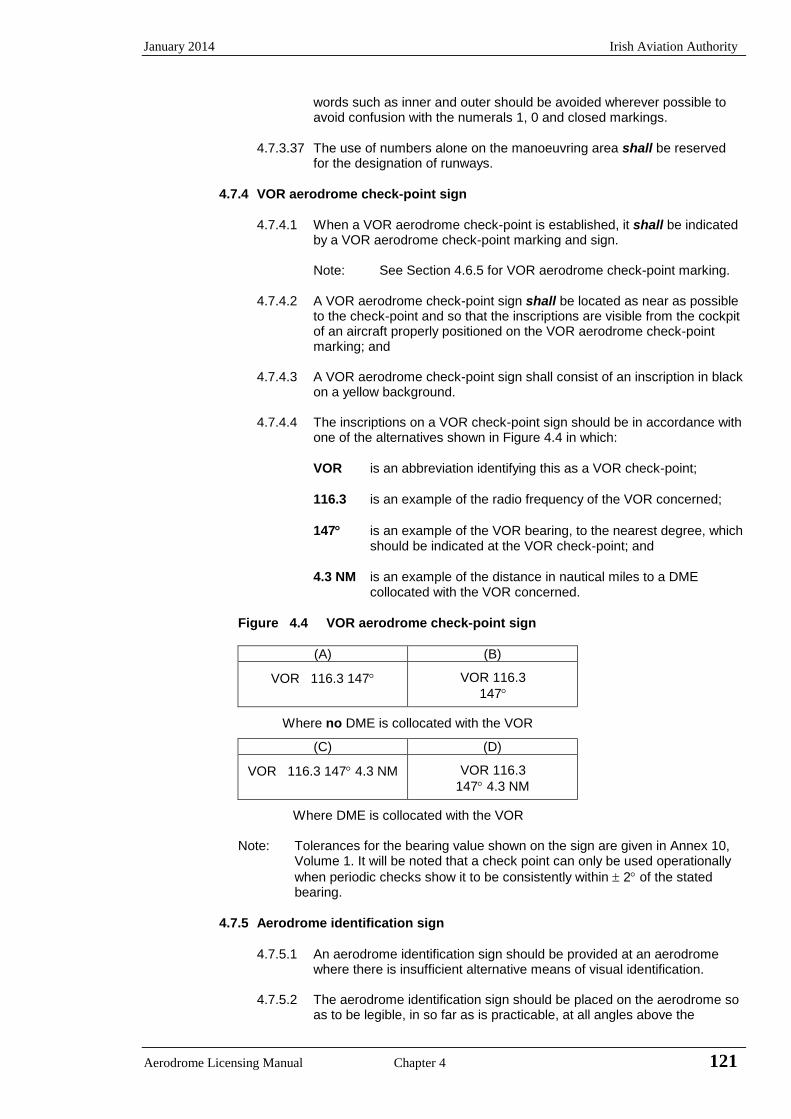
January 2014 Irish Aviation Authority
Aerodrome Licensing Manual Chapter 4 121
words such as inner and outer should be avoided wherever possible to avoid confusion with the numerals 1, 0 and closed markings.
4.7.3.37 The use of numbers alone on the manoeuvring area shall be reserved
for the designation of runways.
4.7.4 VOR aerodrome check-point sign
4.7.4.1 When a VOR aerodrome check-point is established, it shall be indicated by a VOR aerodrome check-point marking and sign.
Note: See Section 4.6.5 for VOR aerodrome check-point marking.
4.7.4.2 A VOR aerodrome check-point sign shall be located as near as possible
to the check-point and so that the inscriptions are visible from the cockpit of an aircraft properly positioned on the VOR aerodrome check-point marking; and
4.7.4.3 A VOR aerodrome check-point sign shall consist of an inscription in black
on a yellow background.
4.7.4.4 The inscriptions on a VOR check-point sign should be in accordance with one of the alternatives shown in Figure 4.4 in which:
VOR is an abbreviation identifying this as a VOR check-point;
116.3 is an example of the radio frequency of the VOR concerned;
147 is an example of the VOR bearing, to the nearest degree, which should be indicated at the VOR check-point; and
4.3 NM is an example of the distance in nautical miles to a DME collocated with the VOR concerned.
Figure 4.4 VOR aerodrome check-point sign
(A) (B)
VOR 116.3 147
VOR 116.3
147
Where no DME is collocated with the VOR
(C) (D)
VOR 116.3 147 4.3 NM
VOR 116.3
147 4.3 NM
Where DME is collocated with the VOR
Note: Tolerances for the bearing value shown on the sign are given in Annex 10,
Volume 1. It will be noted that a check point can only be used operationally
when periodic checks show it to be consistently within 2 of the stated bearing.
4.7.5 Aerodrome identification sign
4.7.5.1 An aerodrome identification sign should be provided at an aerodrome
where there is insufficient alternative means of visual identification.
4.7.5.2 The aerodrome identification sign should be placed on the aerodrome so as to be legible, in so far as is practicable, at all angles above the
Irish Aviation Authority January 2014
122 Chapter 4 Aerodrome Licensing Manual
horizontal.
4.7.5.3 The aerodrome identification sign shall consist of the name of the aerodrome.
4.7.5.4 The colour selected for the sign should give adequate conspicuity when
viewed against its background.
4.7.5.5 The characters should have a height of not less than 3 m.
4.7.6 Aircraft stand identification signs
4.7.6.1 An aircraft stand identification marking should be supplemented with an aircraft stand identification sign where feasible.
4.7.6.2 An aircraft stand identification sign should be located so as to be clearly
visible from the cockpit of an aircraft prior to entering the aircraft stand.
4.7.6.3 An aircraft stand identification sign should consist of an inscription in black on a yellow background.
4.7.7 Road-holding position sign
4.7.7.1 A road-holding position sign shall be provided at all road entrances to a runway.
4.7.7.2 The road-holding position sign shall be located 1.5 m from the left edge
of the road at the holding position.
4.7.7.3 A road-holding position sign shall consist of an inscription in white on a red background.
4.7.7.4 The inscription on a road-holding position sign shall be in the national
language, be in conformity with the local traffic regulations and include the following:
a) a requirement to stop; and
b) where appropriate:
(1) a requirement to obtain ATC clearance and
(2) a location designator.
Note: Examples of road-holding position signs are contained in the Aerodrome
Design Manual, Part 4 (Doc 9157).
4.7.7.5 A road-holding position sign intended for night use shall be retroreflective or illuminated.

January 2014 Irish Aviation Authority
Aerodrome Licensing Manual Chapter 4 123
4.8 Markers
4.8.1 General
4.8.1.1 Markers shall be frangible. Those located near a runway or taxiway shall be sufficiently low to preserve clearance for propellers and for engine pods of jet aircraft.
Notes: 1 Anchors or chains, to prevent markers which have broken from their
mounting from blowing away, are sometimes used. 2 Guidance on the frangibility of markers is given in the Aerodrome Design
Manual, Part 6 (Doc 9157).
4.8.2 Unpaved runway edge markers
4.8.2.1 Markers should be provided when the extent of an unpaved runway is not clearly indicated by the appearance of its surface compared with that of the surrounding ground.
4.8.2.2 Where runway lights are provided, the markers should be incorporated in the
light fixtures. Where there are no lights, markers of flat rectangular or conical shape should be placed so as to delimit the runway clearly.
4.8.2.3 The flat rectangular markers should have a minimum size of 1 m by 3 m and
should be placed with their long dimension parallel to the runway centre line. The conical markers should have a height not exceeding 50 cm.
4.8.3 Stopway edge markers
4.8.3.1 Stopway edge markers should be provided when the extent of stopway is not clearly indicated by its appearance compared with that of the surrounding ground.
4.8.3.2 The stopway edge markers shall be sufficiently different from any runway edge
markers used to ensure that the two types of markers cannot be confused.
Note: Markers consisting of small vertical boards camouflaged on the reverse side, as viewed from the runway, have proved operationally acceptable.
4.8.4 Edge markers for snow covered runways
4.8.4.1 Edge markers for snow-covered runways should be used to indicate the usable limits of a snow-covered runway when the limits are not otherwise indicated.
Note: Runway lights could be used to indicate the limits.
4.8.4.2 Edge markers for snow covered runways should be placed along the sides of
the runway at intervals of not more than 100 m, and should be located symmetrically about the runway centre line at such a distance from the centre line that there is adequate clearance for wing tips and power plants. Sufficient markers should be placed across the threshold and end of the runway.
4.8.4.3 Edge markers for snow covered runways should consist of conspicuous objects
such as evergreen trees about 1.5 m high or light-weight markers.
Irish Aviation Authority January 2014
124 Chapter 4 Aerodrome Licensing Manual
4.8.5 Taxiway edge markers
4.8.5.1 Taxiway edge markers should be provided on a taxiway where the code number is 1 or 2 and taxiway centre line or edge lights or taxiway centre line markers are not provided.
4.8.5.2 Taxiway edge markers should be installed at least at the same locations as
would the taxiway edge lights had they been used.
4.8.5.3 A taxiway edge marker shall be retroreflective blue.
4.8.5.4 The marked surface as viewed by the pilot should be a rectangle and should have a minimum viewing area of 150 cm
2.
4.8.5.5 Taxiway edge markers shall be frangible. Their height shall be sufficiently low
to preserve clearance for propellers and for the engine pods of jet aircraft.
4.8.6 Taxiway centre line markers
4.8.6.1 Taxiway centre line markers should be provided on a taxiway where the code number is 1 or 2 and taxiway centre line or edge lights or taxiway edge markers are not provided; and
4.8.6.2 Taxiway centre line markers should be provided on a taxiway where the code
number is 3 or 4 and taxiway centre line lights are not provided if there is need to improve the guidance provided by the taxiway centre line marking.
4.8.6.3 Taxiway centre line markers should be installed at least at the same location as
would taxiway centre line lights had they been used.
4.8.6.4 Taxiway centre line markers should normally be located on the taxiway centre line marking except that they may be offset by not more than 30 cm where it is not practicable to locate them on the marking.
4.8.6.5 A taxiway centre line marker shall be retroreflective green.
4.8.6.6 The marked surface as viewed by the pilot should be a rectangle and should
have a minimum viewing area of 20 cm2.
4.8.6.7 Taxiway centre line markers shall be so designed and fitted as to withstand
being run over by the wheels of an aircraft without damage either to the aircraft or to the markers themselves.
4.8.7 Unpaved taxiway edge markings
4.8.7.1 Where the extent of an unpaved taxiway is not clearly indicated by its appearance compared with that of the surrounding ground, markers should be provided.
4.8.7.2 Where taxiway lights are provided, the markers should be incorporated in the
light fixtures. Where there are no lights, markers of conical shape should be placed so as to delimit the taxiway clearly.
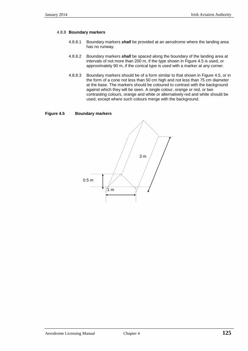
January 2014 Irish Aviation Authority
Aerodrome Licensing Manual Chapter 4 125
4.8.8 Boundary markers
4.8.8.1 Boundary markers shall be provided at an aerodrome where the landing area has no runway.
4.8.8.2 Boundary markers shall be spaced along the boundary of the landing area at
intervals of not more than 200 m, if the type shown in Figure 4.5 is used, or approximately 90 m, if the conical type is used with a marker at any corner.
4.8.8.3 Boundary markers should be of a form similar to that shown in Figure 4.5, or in
the form of a cone not less than 50 cm high and not less than 75 cm diameter at the base. The markers should be coloured to contrast with the background against which they will be seen. A single colour, orange or red, or two contrasting colours, orange and white or alternatively red and white should be used, except where such colours merge with the background.
Figure 4.5 Boundary markers 3 m 0.5 m 1 m

Irish Aviation Authority January 2014
126 Chapter 4 Aerodrome Licensing Manual
INTENTIONALLY BLANK

January 2014 Irish Aviation Authority
Aerodrome Licensing Manual Chapter 4 127
APPENDIX 4A Figures Illustrating Markings and Signs
14.5 m
1.8 m
36.0 m
Runway Centreline
Illustration a) Closed runway marking Illustration b) Closed taxiway marking
Figure 4A.1 Closed runway and Taxiway markings
Figure 4A.2 Pre-threshold marking
9.0 m
3.75 m
Taxiway Centre line Line thickness 1.5m
45
45
30m 30m 30m 30m
7.5m 7.5m
0.9m 7.5m max.
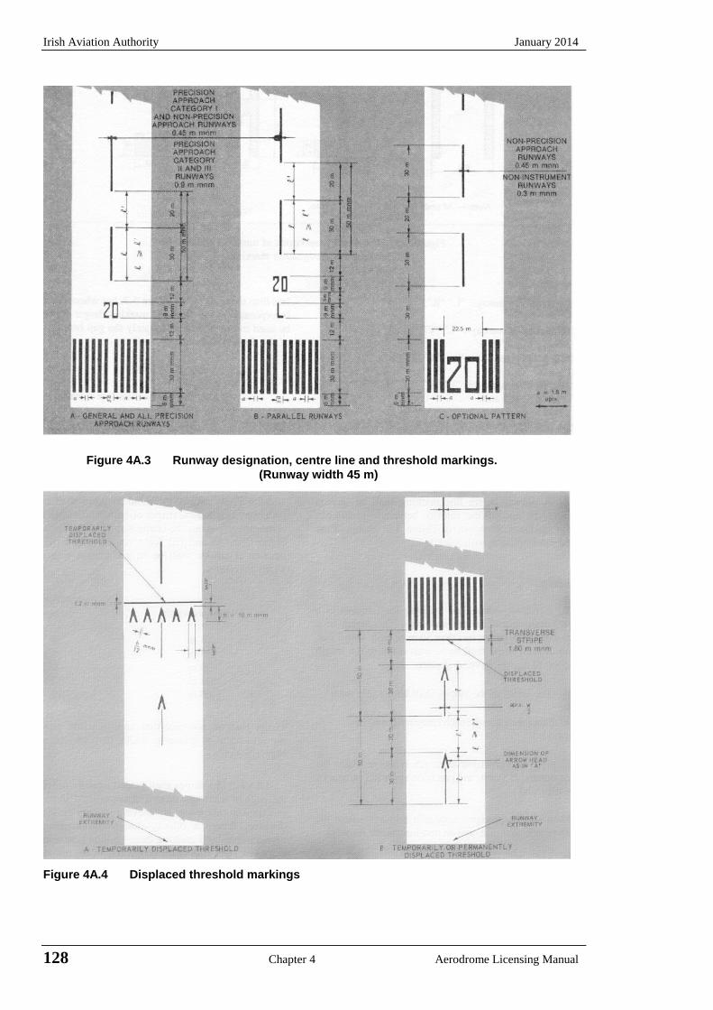
Irish Aviation Authority January 2014
128 Chapter 4 Aerodrome Licensing Manual
Figure 4A.3 Runway designation, centre line and threshold markings.
(Runway width 45 m)
Figure 4A.4 Displaced threshold markings
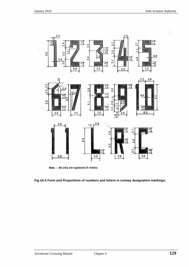
January 2014 Irish Aviation Authority
Aerodrome Licensing Manual Chapter 4 129
Fig 4A.5 Form and Proportions of numbers and letters in runway designation markings:
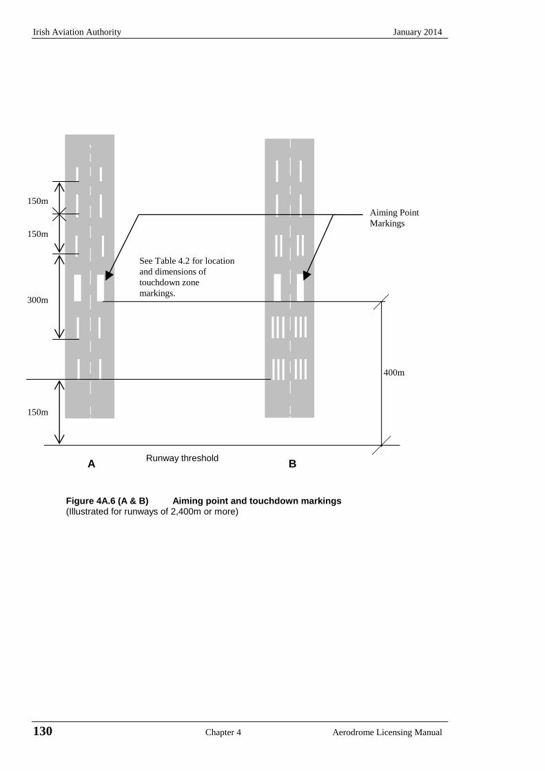
Irish Aviation Authority January 2014
130 Chapter 4 Aerodrome Licensing Manual
A B Figure 4A.6 (A & B) Aiming point and touchdown markings (Illustrated for runways of 2,400m or more)
400m
Runway threshold
150m
150m
150m
See Table 4.2 for location
and dimensions of
touchdown zone
markings. 300m
Aiming Point
Markings
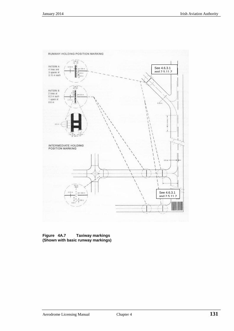
January 2014 Irish Aviation Authority
Aerodrome Licensing Manual Chapter 4 131
Figure 4A.7 Taxiway markings
(Shown with basic runway markings)
See 4.6.3.1 and 2.5.11.2
See 4.6.3.1 and 2.5.11.2
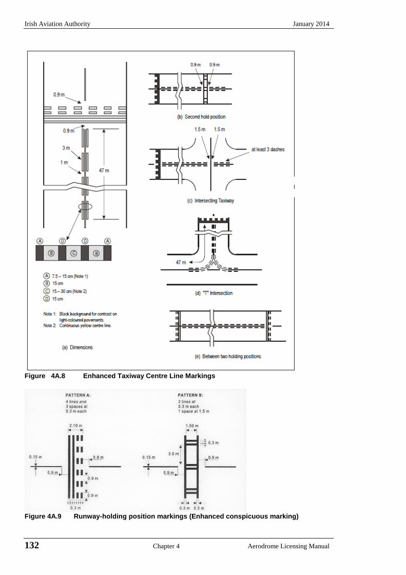
Irish Aviation Authority January 2014
132 Chapter 4 Aerodrome Licensing Manual
Figure 4A.8 Enhanced Taxiway Centre Line Markings
Figure 4A.9 Runway-holding position markings (Enhanced conspicuous marking)
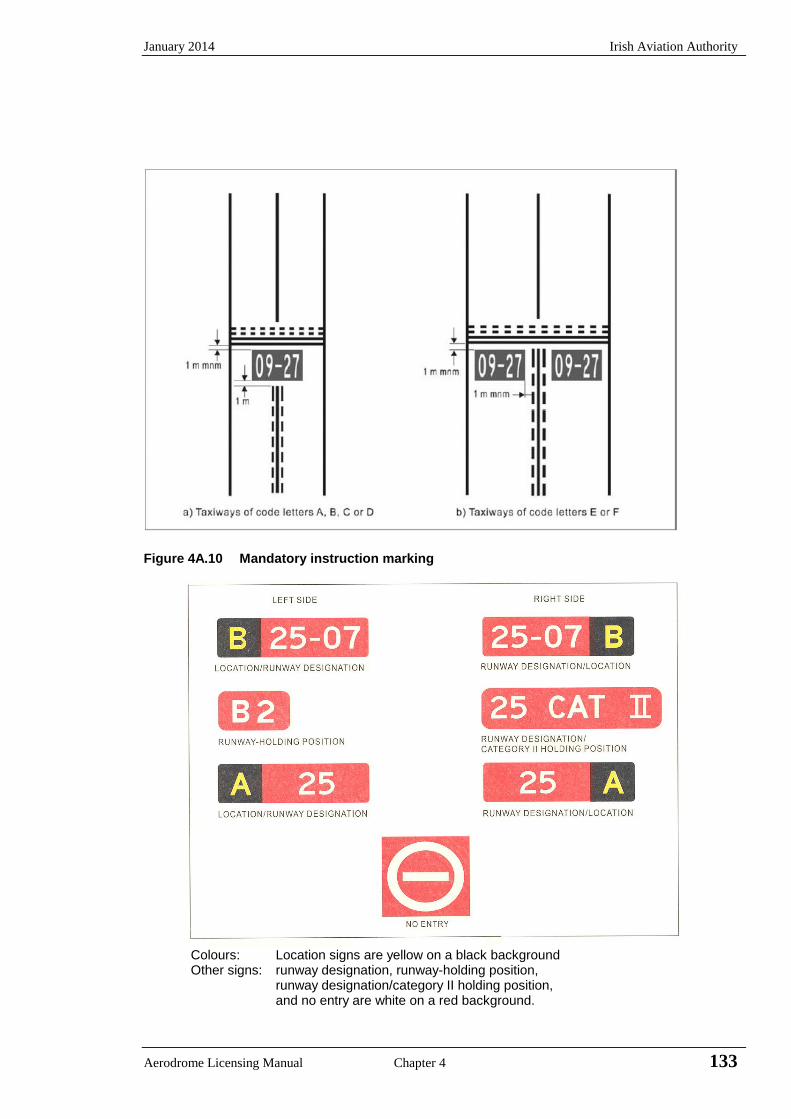
January 2014 Irish Aviation Authority
Aerodrome Licensing Manual Chapter 4 133
Figure 4A.10 Mandatory instruction marking
Colours: Location signs are yellow on a black background Other signs: runway designation, runway-holding position, runway designation/category II holding position, and no entry are white on a red background.

Irish Aviation Authority January 2014
134 Chapter 4 Aerodrome Licensing Manual
Figure 4A.11 Mandatory instruction signs
Colours: Location signs are yellow on a black background. Other signs: direction, destination, runway vacated, runway exit and intersection take-off are
black on a yellow background.
Figure 4A.12 Information signs
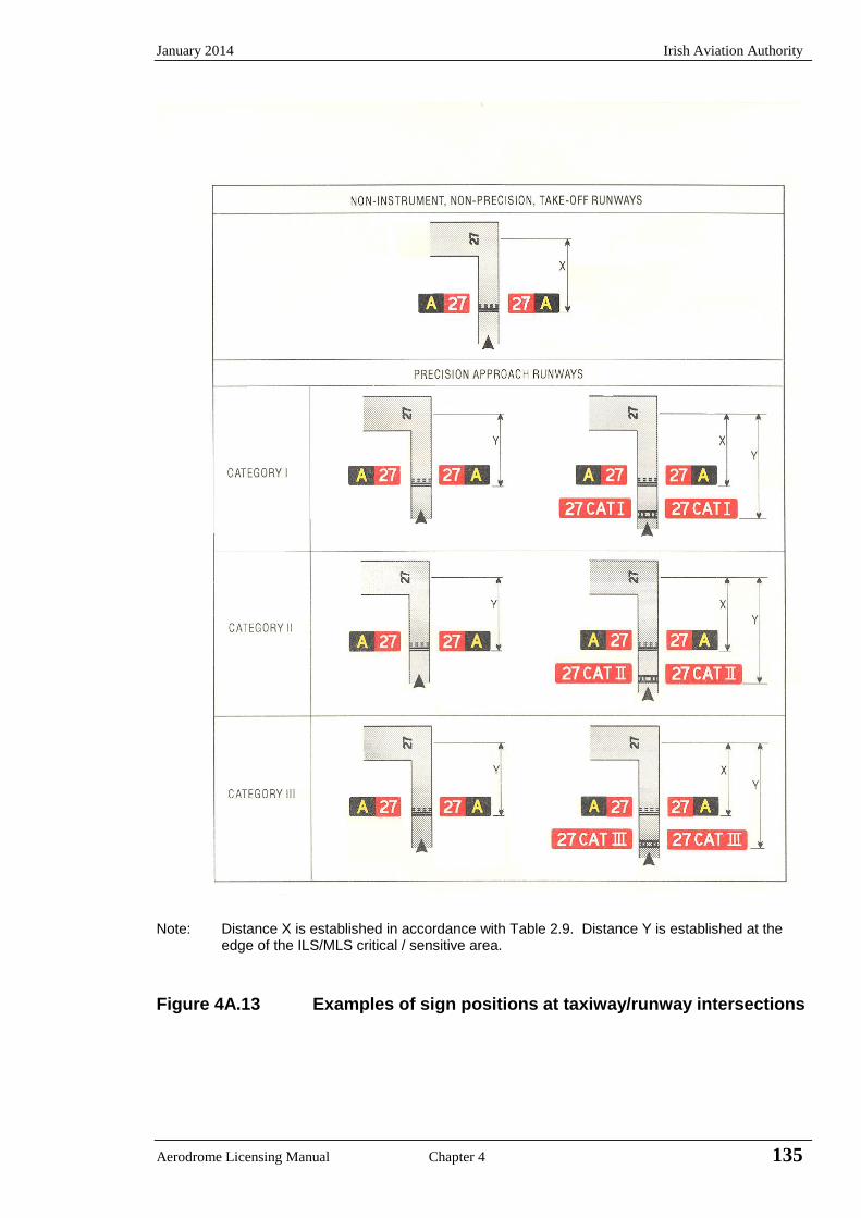
January 2014 Irish Aviation Authority
Aerodrome Licensing Manual Chapter 4 135
Note: Distance X is established in accordance with Table 2.9. Distance Y is established at the
edge of the ILS/MLS critical / sensitive area.
Figure 4A.13 Examples of sign positions at taxiway/runway intersections

Irish Aviation Authority January 2014
136 Chapter 4 Aerodrome Licensing Manual
INTENTIONALLY BLANK

January 2014 Irish Aviation Authority
Aerodrome Licensing Manual Chapter 4 137
APPENDIX 4B Mandatory Instruction and Information Markings
This Appendix details the form and proportions of the letters, numbers and symbols of mandatory instruction markings and information markings on a 20 cm grid.
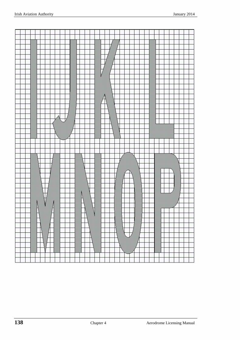
Irish Aviation Authority January 2014
138 Chapter 4 Aerodrome Licensing Manual
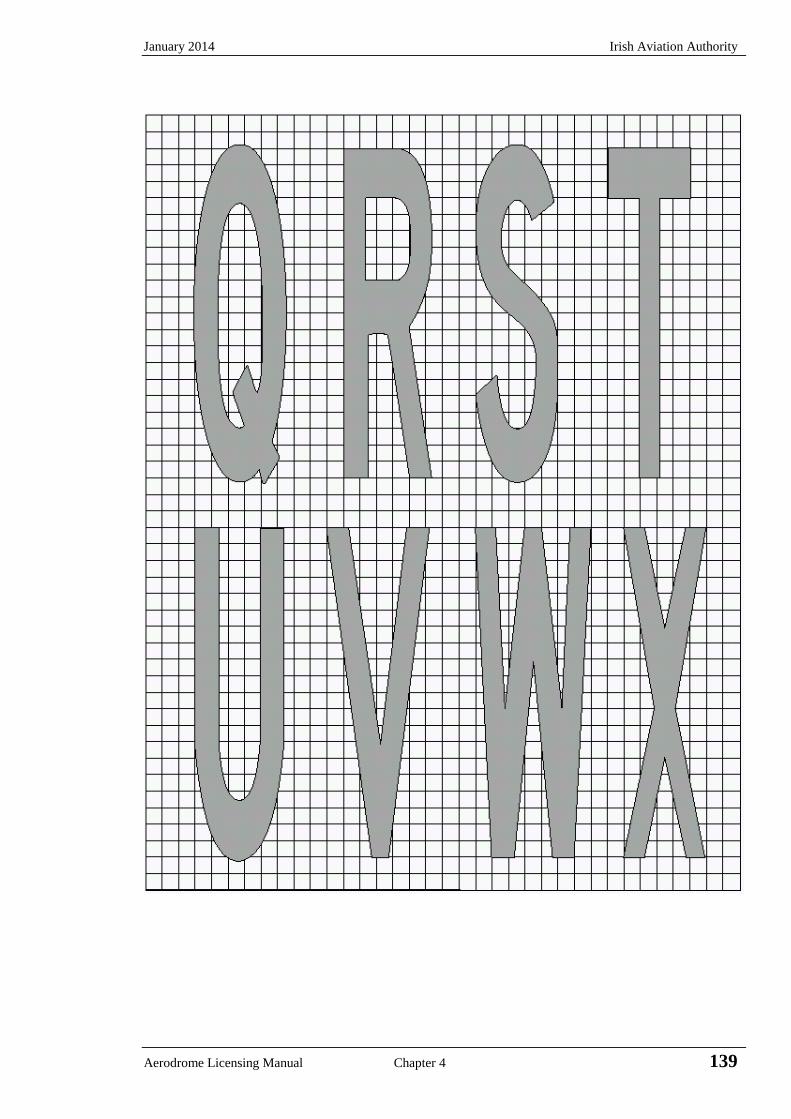
January 2014 Irish Aviation Authority
Aerodrome Licensing Manual Chapter 4 139
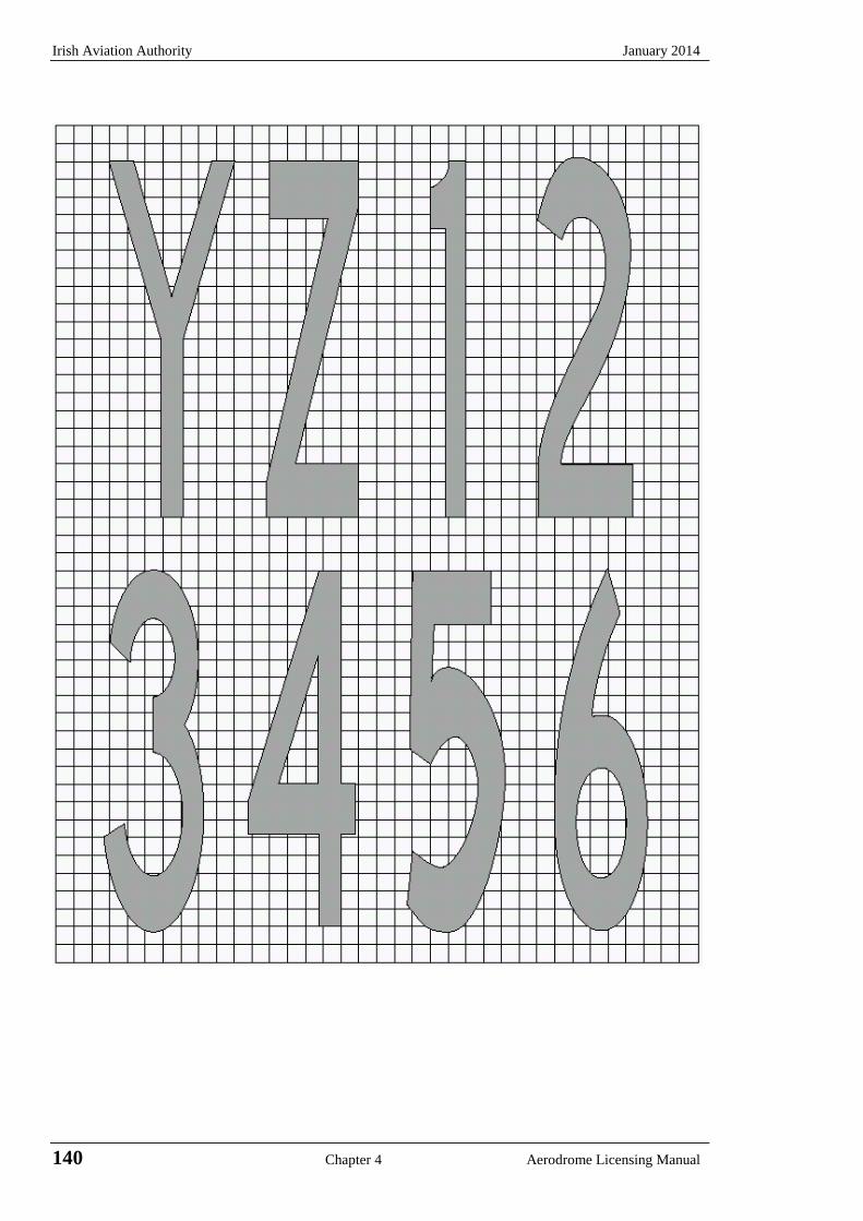
Irish Aviation Authority January 2014
140 Chapter 4 Aerodrome Licensing Manual
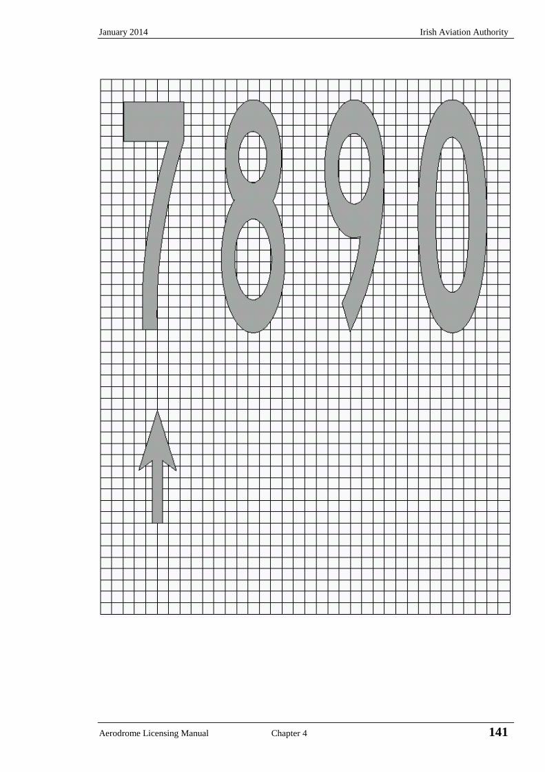
January 2014 Irish Aviation Authority
Aerodrome Licensing Manual Chapter 4 141

Irish Aviation Authority January 2014
142 Chapter 4 Aerodrome Licensing Manual
INTENTIONALLY BLANK
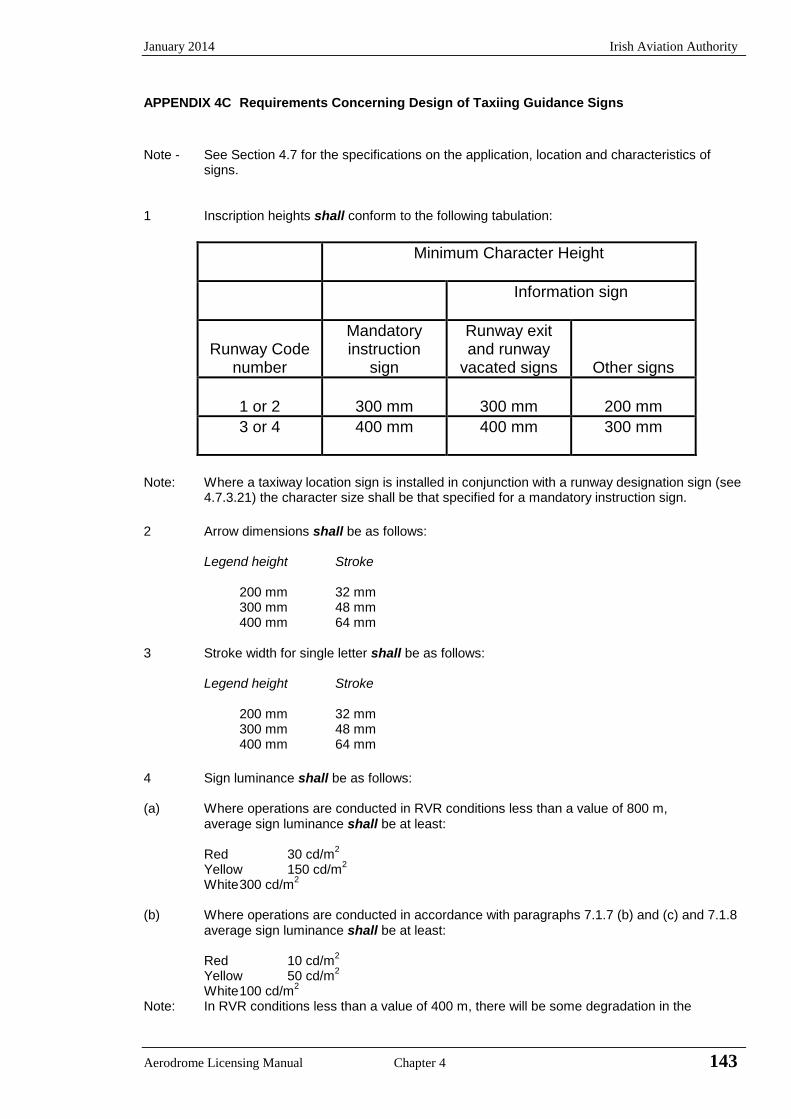
January 2014 Irish Aviation Authority
Aerodrome Licensing Manual Chapter 4 143
APPENDIX 4C Requirements Concerning Design of Taxiing Guidance Signs
Note - See Section 4.7 for the specifications on the application, location and characteristics of
signs. 1 Inscription heights shall conform to the following tabulation:
Minimum Character Height
Information sign
Runway Code
number
Mandatory instruction
sign
Runway exit and runway
vacated signs
Other signs
1 or 2
300 mm
300 mm
200 mm
3 or 4 400 mm 400 mm 300 mm
Note: Where a taxiway location sign is installed in conjunction with a runway designation sign (see
4.7.3.21) the character size shall be that specified for a mandatory instruction sign.
2 Arrow dimensions shall be as follows: Legend height Stroke 200 mm 32 mm 300 mm 48 mm 400 mm 64 mm 3 Stroke width for single letter shall be as follows: Legend height Stroke 200 mm 32 mm 300 mm 48 mm 400 mm 64 mm
4 Sign luminance shall be as follows: (a) Where operations are conducted in RVR conditions less than a value of 800 m,
average sign luminance shall be at least: Red 30 cd/m
2
Yellow 150 cd/m2
White 300 cd/m2
(b) Where operations are conducted in accordance with paragraphs 7.1.7 (b) and (c) and 7.1.8
average sign luminance shall be at least: Red 10 cd/m
2
Yellow 50 cd/m2
White 100 cd/m2
Note: In RVR conditions less than a value of 400 m, there will be some degradation in the
Irish Aviation Authority January 2014
144 Chapter 4 Aerodrome Licensing Manual
performance of signs. 5 The luminance ratio between red and white elements of a mandatory sign shall be between
1:5 and 1:10. 6 The average luminance of a sign is calculated by establishing grid points as shown in Annex
14, Appendix 4, figure A4.1 and using the luminance values measured at all the grid points located within the rectangle representing the sign. The average value is the arithmetic average of the luminance values measured at all considered grid points.
7. The average value is the arithmetic average of the luminance values measured at all
considered grid points. Note - Guidance on measuring the average luminance of a sign is contained in the Aerodrome
Design Manual, Part 4 (Doc 9157).
8. The ratio between luminance values of adjacent grid points shall not exceed 1.5:1. For
areas on the sign face where the grid spacing is 7.5 cm, the ratio between luminance values of adjacent grid points shall not exceeds 1.25:1. The ratio between the maximum and minimum luminance value over the whole sign face shall not exceed 5:1
9 The forms of characters, (letters, numbers, arrows and symbols), shall conform to those
shown in Figure 4C.2. The width of characters and the space between individual characters shall be determined as indicated in Table 4C.1.
Note: See Annex 14, Appendix 4 and Aerodrome Design Manual, Part 4 (Doc 9157) for guidance
on measuring average luminance of a sign.
10 The face height of the signs shall be as follows: Legend height Face height 200 mm 400 mm 300 mm 600 mm 400 mm 800 mm 11 The face width of the sign shall be determined using Figure 4C.1 except that, where a
mandatory instruction sign is provided on one side of a taxiway only, the face shall not be less than:
(a) 1.94 m where the code number is 3 or 4 (b) 1.46 m where the code number is 1 or 2.
Note: Additional guidance on determining the face width of a sign is contained in the Aerodrome
Design Manual, Part 4 (Doc 9157). 12 Borders:
(a) The black vertical delineator between adjacent direction signs should have a width of approximately 0.7 of the stroke width;
(b) The yellow border on a stand alone location sign should be approximately 0.5 of the stroke width.
13 The colours of signs shall be in accordance with the appropriate specifications in Annex 14
Appendix 1.

January 2014 Irish Aviation Authority
Aerodrome Licensing Manual Chapter 4 145
Table 4C.1 Letter and numeral widths and space between letters or numerals
(a) Letter to letter code number (d) Width of letter
Following letter Letter height (mm)
Preceding
letter
B, D, E, F, H, I, K, L,
M, N, P, R, U
C, G, O, Q, S, X, Z
A, J, T, V, W, Y
Letter
200
300
400
Code number Width (mm)
A 2 2 4 A 170 255 340 B 1 2 2 B 137 205 274 C 2 2 3 C 137 205 274 D 1 2 2 D 137 205 274 E 2 2 3 E 124 186 248 F 2 2 3 F 124 186 248 G 1 2 2 G 137 205 274 H 1 1 2 H 137 205 274 I 1 1 2 I 32 48 64 J 1 1 2 J 127 190 254 K 2 2 3 K 140 210 280 L 2 2 4 L 124 186 248 M 1 1 2 M 157 236 314 N 1 1 2 N 137 205 274 O 1 2 2 O 143 214 286 P 1 2 2 P 137 205 274 Q 1 2 2 Q 143 214 286 R 1 2 2 R 137 205 274 S 1 2 2 S 137 205 274 T 2 2 4 T 124 186 248 U 1 1 2 U 137 205 274 V 2 2 4 V 152 229 304 W 2 2 4 W 178 267 356 X 2 2 3 X 137 205 274 Y 2 2 4 Y 171 257 342 Z 2 2 3 Z 137 205 274
(b) Numeral to numeral code number (e) Width of numeral
Following number Numeral height (mm)
Preceding Numeral
1, 5
2, 3, 6, 8, 9, 0
4, 7
Numeral 200 300 400
Code number Width (mm)
1 1 1 2 1 50 74 98 2 1 2 2 2 137 205 274 3 1 2 2 3 137 205 274 4 2 2 4 4 149 224 298 5 1 2 2 5 137 205 274 6 1 2 2 6 137 205 274 7 2 2 4 7 137 205 274 8 1 2 2 8 137 205 274 9 1 2 2 9 137 205 274 0 1 2 2 0 143 214 286
(c) Space between characters
Letter Height (mm) Code No. 200 300 400
Space (mm)
1 48 71 96 2 38 57 76 3 25 38 50 4 13 19 26
2. The space between words or groups of characters forming an abbreviation or symbol should be equal to 0.5 to 0.75 of the height of characters used, except that where an arrow is located with a single character such as
'A ' the space may be reduced to not less than one quarter of the character of the height in order to provide a good visual balance. 3. Where the numeral follows a letter or vice-versa use code 1.
4. Where a hyphen, dot or diagonal stroke follows a character or vice-versa use code 1.
Instructions for using Table 4C.1 1. To determine the proper space between letters or numerals obtain the code number from Table (a) or (b) and enter Table (c) for that code number to the desired letter or numeral height.
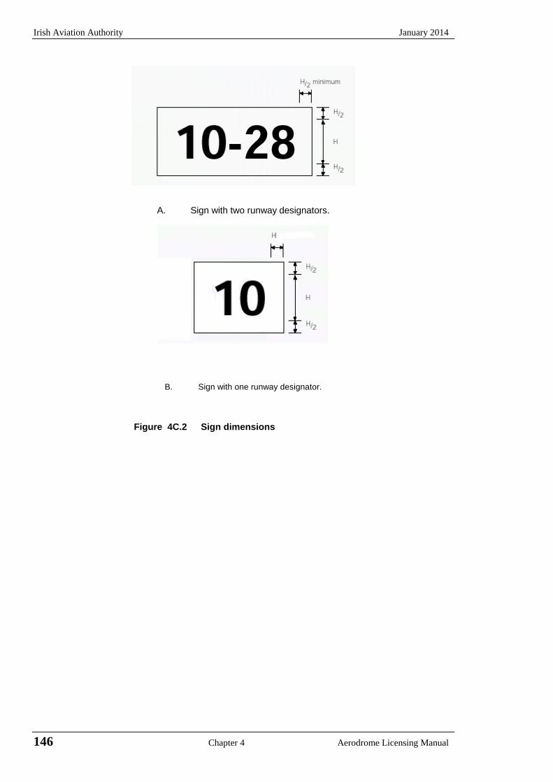
Irish Aviation Authority January 2014
146 Chapter 4 Aerodrome Licensing Manual
A. Sign with two runway designators.
B. Sign with one runway designator.
Figure 4C.2 Sign dimensions
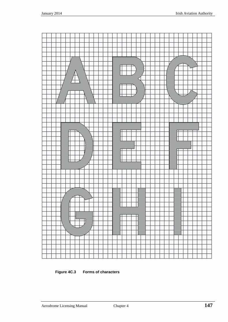
January 2014 Irish Aviation Authority
Aerodrome Licensing Manual Chapter 4 147
Figure 4C.3 Forms of characters
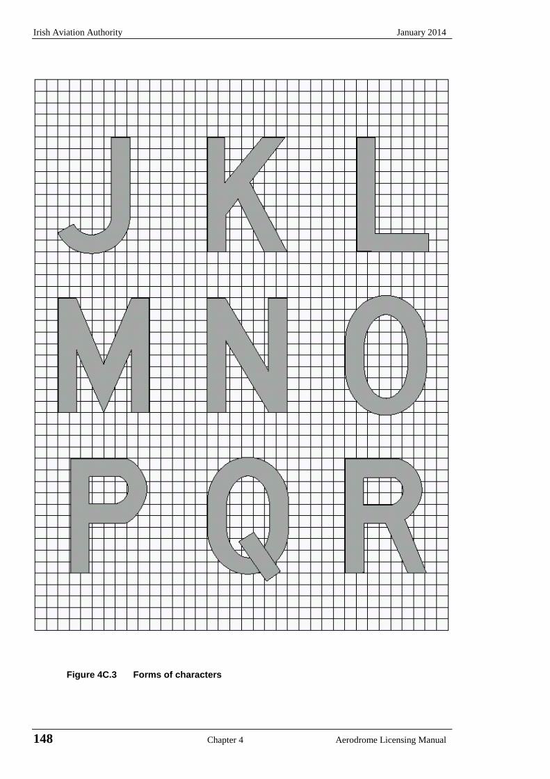
Irish Aviation Authority January 2014
148 Chapter 4 Aerodrome Licensing Manual
Figure 4C.3 Forms of characters
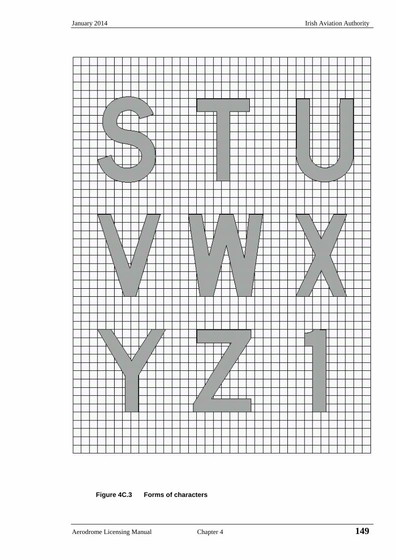
January 2014 Irish Aviation Authority
Aerodrome Licensing Manual Chapter 4 149
Figure 4C.3 Forms of characters
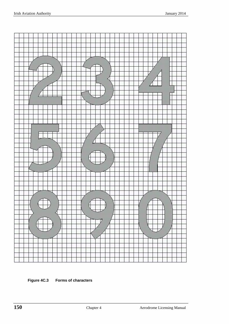
Irish Aviation Authority January 2014
150 Chapter 4 Aerodrome Licensing Manual
Figure 4C.3 Forms of characters
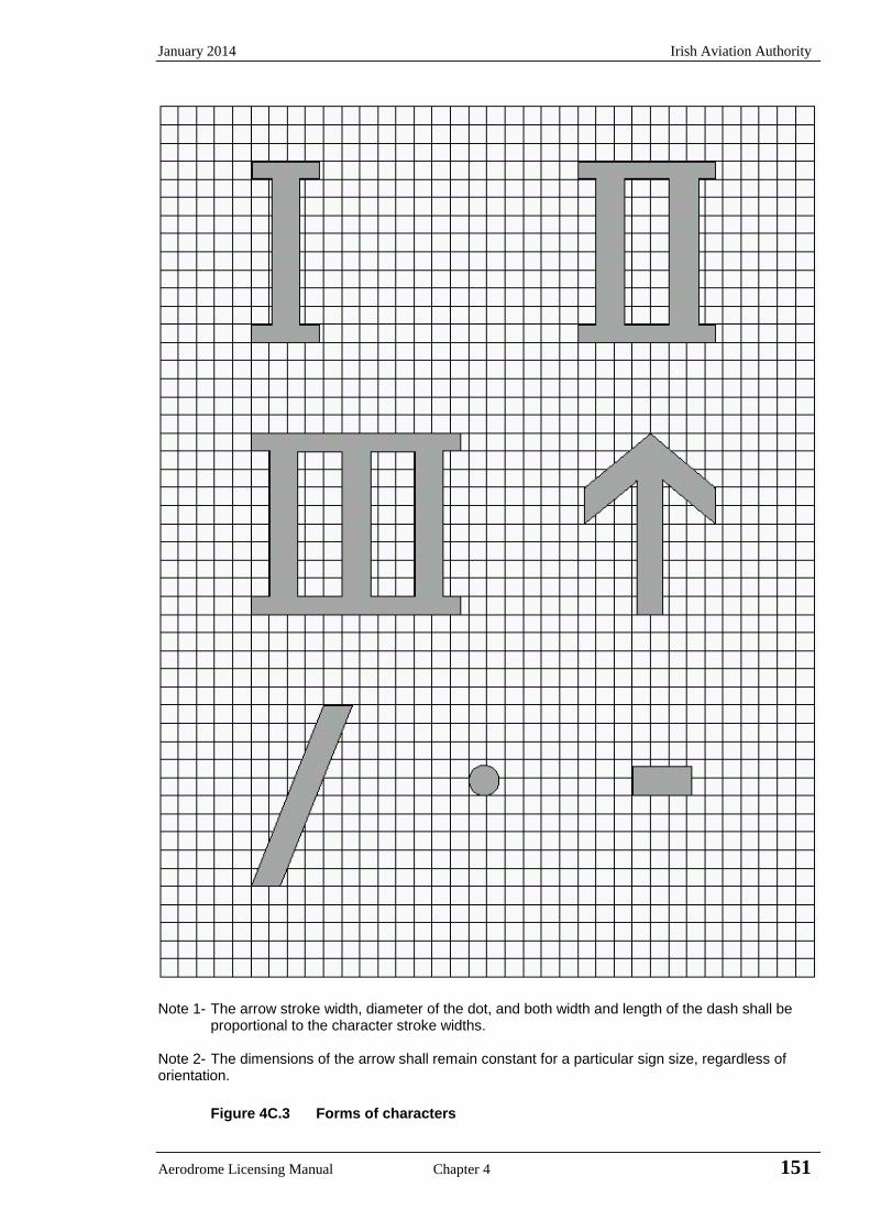
January 2014 Irish Aviation Authority
Aerodrome Licensing Manual Chapter 4 151
Note 1- The arrow stroke width, diameter of the dot, and both width and length of the dash shall be
proportional to the character stroke widths. Note 2- The dimensions of the arrow shall remain constant for a particular sign size, regardless of orientation.
Figure 4C.3 Forms of characters
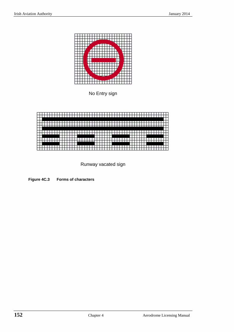
Irish Aviation Authority January 2014
152 Chapter 4 Aerodrome Licensing Manual
No Entry sign
Runway vacated sign
Figure 4C.3 Forms of characters
January 2014 Irish Aviation Authority
Aerodrome Licensing Manual Chapter 5 153
CHAPTER 5 THE ASSESSMENT AND TREATMENT OF OBSTACLES
5.1 Introduction
5.1.1 The effective use of an aerodrome may be considerably influenced by natural features
and man made construction inside and outside its boundary. These may result in limitations on the distances available for take-off and landing and on the range of meteorological conditions in which the take-off and landing can be undertaken. For these reasons certain areas of the local airspace must be regarded as integral parts of the aerodrome environment. The degree of freedom from obstacles in these areas is as important to the safe and efficient use of the aerodrome as are the more obvious physical requirements of the runways and their associated strips.
5.1.2 The method of assessing the significance of any proposed object within the aerodrome
boundary or in the vicinity of an aerodrome is to define obstacle limitation surfaces particular to a runway and its intended use. The purpose of this Chapter is to define these obstacle limitation surfaces and their characteristics and to describe the action to be taken in respect of objects which penetrate them. In ideal circumstances all surfaces will be free from obstacles but when a surface is infringed, any safety measures required by the Authority will have regard to:
a) the nature of the obstacle and its location relative to the surface origin, to the
extended centre line of the runway or normal approach and departure paths and to existing obstructions;
b) the amount by which the surface is infringed; c) the gradient presented by the obstacle to the surface origin; d) the volume and type of air traffic at the aerodrome; and e) the instrument approach procedures published for the aerodrome.
5.1.3 Safety measures could be as follows:
a) promulgation in AIP-Ireland of appropriate information; b) marking and/or lighting of the object; c) variation of the runway distances declared as available; d) limitation of the use of the runway to visual approaches only; and e) restrictions on the type or amount of traffic.
5.1.4 In addition to the requirements prescribed in this Chapter it may be necessary to call for
other restrictions to development on and in the vicinity of the aerodrome in order to protect the performance of visual and electronic aids to navigation and to ensure that such development does not affect instrument approach procedures and associated obstacle clearance limits.
5.2 Obstacle Limitation Surfaces
Note: The conical surface, inner horizontal surface, approach surface, transitional surfaces, and take-off climb surface are illustrated at Figure 5.1. The outer horizontal surface (not illustrated) extends from the periphery of the conical surface to within a specified radius centred on the aerodrome reference point. The obstacle free zone (OFZ) including the inner approach surface, the inner transitional surfaces and the balked landing surface are illustrated at Figure 5.2. Guidance on the obstacle limitation surfaces is contained in the Aerodrome Services Manual, Part 6 (Doc 9137).
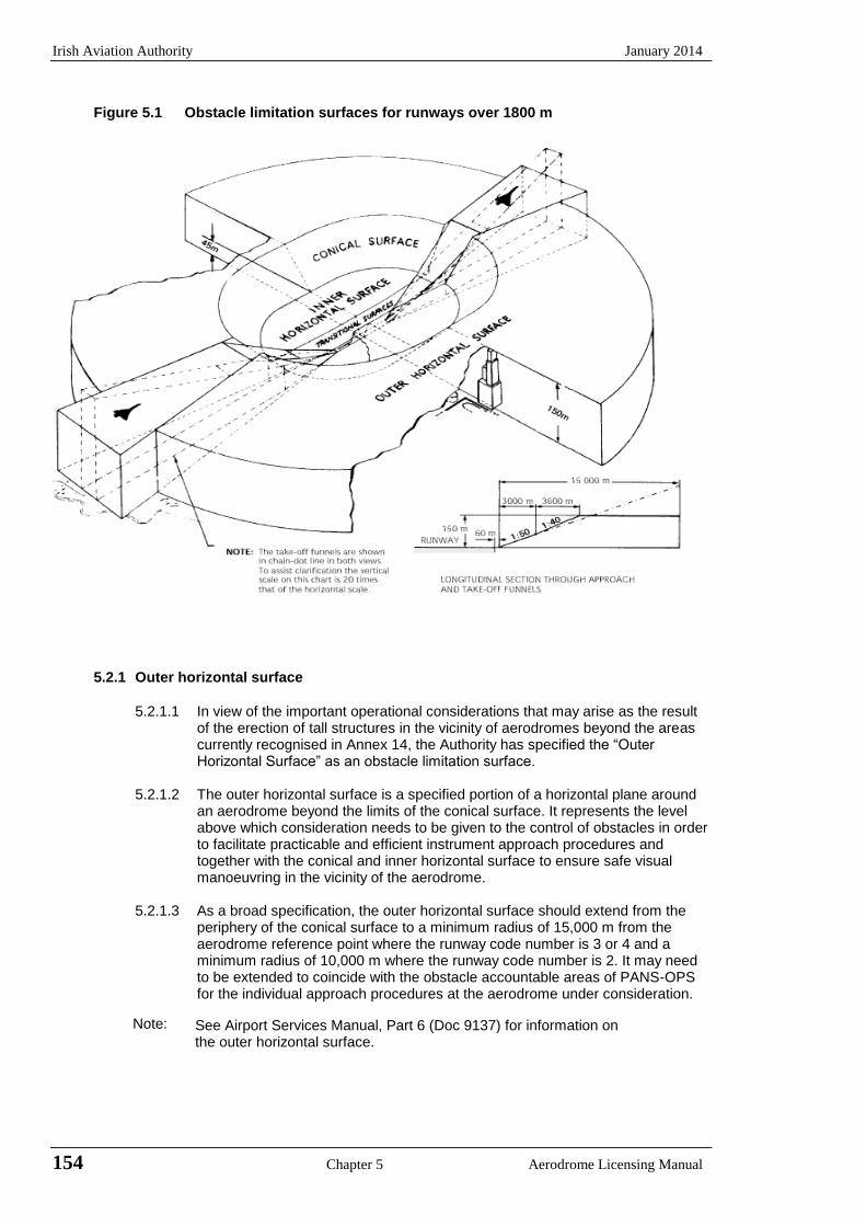
Irish Aviation Authority January 2014
154 Chapter 5 Aerodrome Licensing Manual
Figure 5.1 Obstacle limitation surfaces for runways over 1800 m
5.2.1 Outer horizontal surface
5.2.1.1 In view of the important operational considerations that may arise as the result of the erection of tall structures in the vicinity of aerodromes beyond the areas currently recognised in Annex 14, the Authority has specified the “Outer Horizontal Surface” as an obstacle limitation surface.
5.2.1.2 The outer horizontal surface is a specified portion of a horizontal plane around an aerodrome beyond the limits of the conical surface. It represents the level above which consideration needs to be given to the control of obstacles in order to facilitate practicable and efficient instrument approach procedures and together with the conical and inner horizontal surface to ensure safe visual manoeuvring in the vicinity of the aerodrome.
5.2.1.3 As a broad specification, the outer horizontal surface should extend from the periphery of the conical surface to a minimum radius of 15,000 m from the aerodrome reference point where the runway code number is 3 or 4 and a minimum radius of 10,000 m where the runway code number is 2. It may need to be extended to coincide with the obstacle accountable areas of PANS-OPS for the individual approach procedures at the aerodrome under consideration.
Note: See Airport Services Manual, Part 6 (Doc 9137) for information on the outer horizontal surface.
January 2014 Irish Aviation Authority
Aerodrome Licensing Manual Chapter 5 155
5.2.2 Conical surface
5.2.2.1 The conical surface is a surface sloping upwards and outwards from the periphery of the inner horizontal surface:
5.2.2.2 The limits of the conical surface shall comprise:
a) a lower edge coincident with the periphery of the inner horizontal surface;and
b) an upper edge located at the height above the inner horizontal surfacespecified in Table 5.1
Table 5.1 Height of upper edge above the inner horizontal surface
Runway Code number
Non-instrument approach
Non-precision approach
Precision approach category I
Precision approach
category II and III
1 35 m 60 m 60 m -
2 55 m 60 m 60 m -
3 75 m 75 m 100 m 100 m
4 100 m 100 m 100 m 100 m
Note: The conical surface should be extended upwards to the height of the outer horizontal surface.
5.2.2.3 The slope of the conical surface shall be measured in the vertical plane perpendicular to the periphery of the inner horizontal surface. The slope is 5 % for all combinations of runway code number and types of approach.
5.2.3 Inner horizontal surface
5.2.3.1 The inner horizontal surface is a surface located in a horizontal plane above an aerodrome and its environs.
5.2.3.2 The radius or outer limits of the inner horizontal surface shall be measured by using circular arcs centred on the runway ends and joined tangentially by straight lines, thus producing a racetrack pattern. To protect two or more widely spaced runways, a more complex pattern could become necessary involving four or more circular arcs. The radii of the circular arcs vary with the runway code number and the type of approach and are specified in Table 5.2.
Note: The shape of the inner horizontal surface need not necessarily be circular. Guidance on determining the extent of the inner horizontal surface is contained in the Airport Services Manual, Part 1 (Doc 9137).
5.2.3.3 The height of the inner horizontal surface shall be 45m above the elevation
datum established for that purpose. The location of the datum shall be agreed with the Authority
Note: Guidance on determining the elevation datum is contained in the Airport Services Manual, Part 6 (Doc 9137).
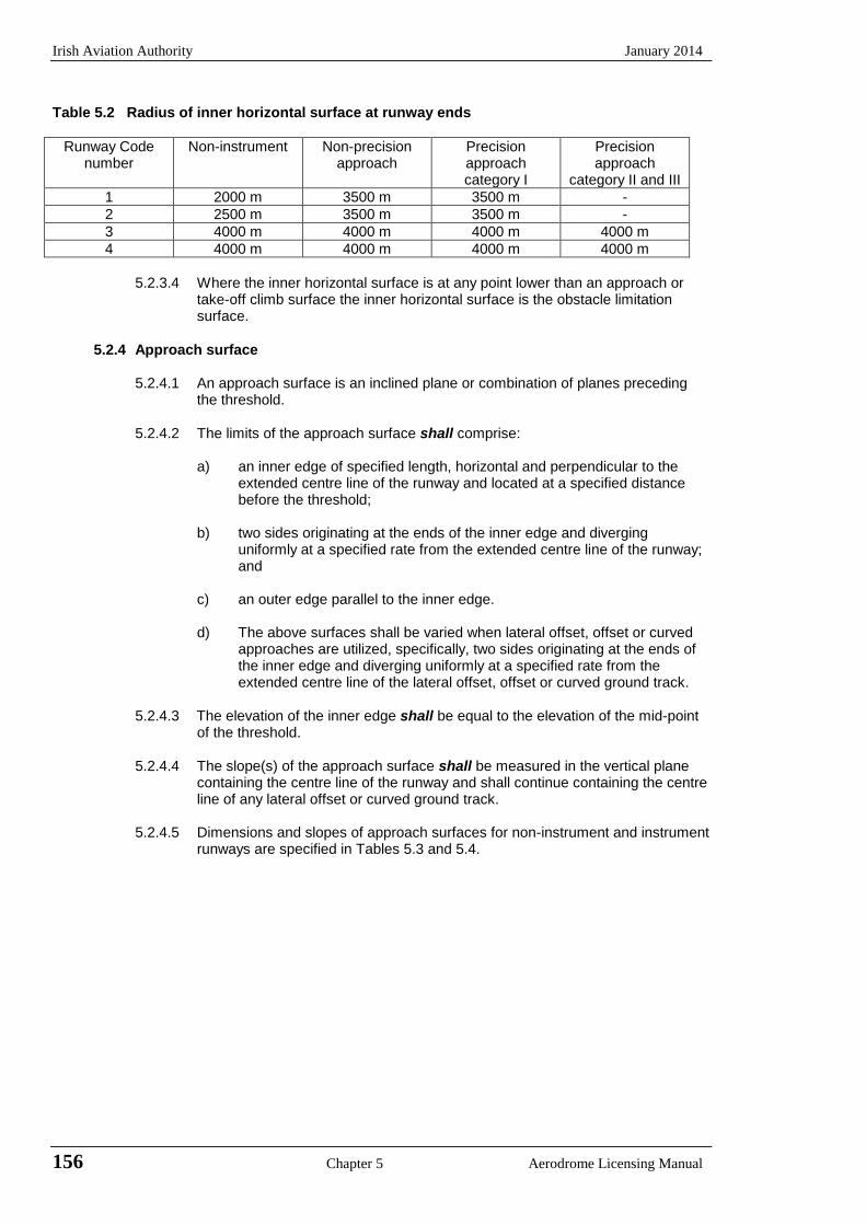
Irish Aviation Authority January 2014
156 Chapter 5 Aerodrome Licensing Manual
Table 5.2 Radius of inner horizontal surface at runway ends
Runway Code number
Non-instrument Non-precision approach
Precision approach category I
Precision approach
category II and III
1 2000 m 3500 m 3500 m -
2 2500 m 3500 m 3500 m -
3 4000 m 4000 m 4000 m 4000 m
4 4000 m 4000 m 4000 m 4000 m
5.2.3.4 Where the inner horizontal surface is at any point lower than an approach or
take-off climb surface the inner horizontal surface is the obstacle limitation surface.
5.2.4 Approach surface
5.2.4.1 An approach surface is an inclined plane or combination of planes preceding the threshold.
5.2.4.2 The limits of the approach surface shall comprise:
a) an inner edge of specified length, horizontal and perpendicular to the extended centre line of the runway and located at a specified distance before the threshold; b) two sides originating at the ends of the inner edge and diverging
uniformly at a specified rate from the extended centre line of the runway; and
c) an outer edge parallel to the inner edge. d) The above surfaces shall be varied when lateral offset, offset or curved
approaches are utilized, specifically, two sides originating at the ends of the inner edge and diverging uniformly at a specified rate from the extended centre line of the lateral offset, offset or curved ground track.
5.2.4.3 The elevation of the inner edge shall be equal to the elevation of the mid-point
of the threshold.
5.2.4.4 The slope(s) of the approach surface shall be measured in the vertical plane containing the centre line of the runway and shall continue containing the centre line of any lateral offset or curved ground track.
5.2.4.5 Dimensions and slopes of approach surfaces for non-instrument and instrument
runways are specified in Tables 5.3 and 5.4.
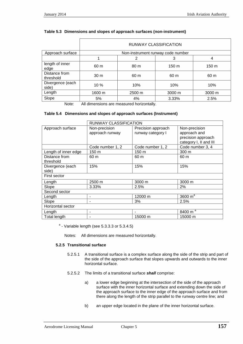
January 2014 Irish Aviation Authority
Aerodrome Licensing Manual Chapter 5 157
Table 5.3 Dimensions and slopes of approach surfaces (non-instrument)
RUNWAY CLASSIFICATION
Approach surface Non-instrument runway code number
1 2 3 4
length of inner edge
60 m 80 m 150 m 150 m
Distance from threshold
30 m 60 m 60 m 60 m
Divergence (each side)
10 % 10% 10% 10%
Length 1600 m 2500 m 3000 m 3000 m
Slope 5% 4% 3.33% 2.5%
Note: All dimensions are measured horizontally.
Table 5.4 Dimensions and slopes of approach surfaces (Instrument)
RUNWAY CLASSIFICATION
Approach surface Non-precision approach runway
Precision approach runway category I
Non-precision approach and precision approach category I, II and III
Code number 1, 2 Code number 1, 2 Code number 3, 4
Length of inner edge 150 m 150 m 300 m
Distance from threshold
60 m 60 m 60 m
Divergence (each side)
15% 15% 15%
First sector
Length 2500 m 3000 m 3000 m
Slope 3.33% 2.5% 2%
Second sector
Length - 12000 m 3600 ma
Slope - 3% 2.5%
Horizontal sector
Length - - 8400 m a
Total length - 15000 m 15000 m
a - Variable length (see 5.3.3.3 or 5.3.4.5)
Notes: All dimensions are measured horizontally.
5.2.5 Transitional surface
5.2.5.1 A transitional surface is a complex surface along the side of the strip and part of the side of the approach surface that slopes upwards and outwards to the inner horizontal surface.
5.2.5.2 The limits of a transitional surface shall comprise:
a) a lower edge beginning at the intersection of the side of the approach surface with the inner horizontal surface and extending down the side of
the approach surface to the inner edge of the approach surface and from there along the length of the strip parallel to the runway centre line; and
b) an upper edge located in the plane of the inner horizontal surface.
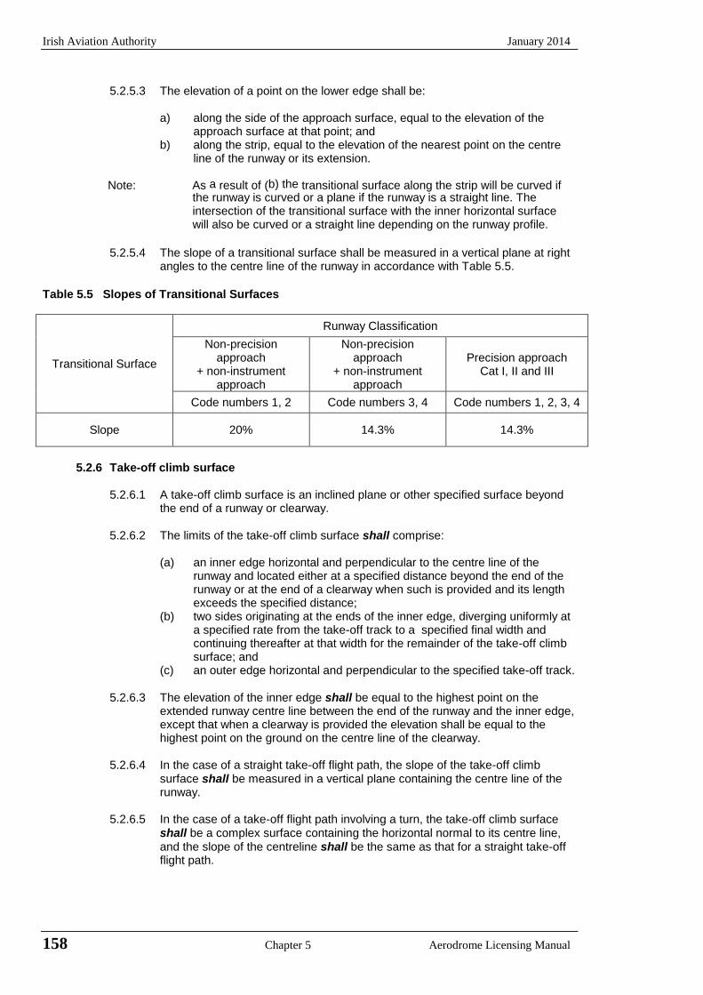
Irish Aviation Authority January 2014
158 Chapter 5 Aerodrome Licensing Manual
5.2.5.3 The elevation of a point on the lower edge shall be:
a) along the side of the approach surface, equal to the elevation of theapproach surface at that point; and
b) along the strip, equal to the elevation of the nearest point on the centreline of the runway or its extension.
Note: As a result of (b) the transitional surface along the strip will be curved if the runway is curved or a plane if the runway is a straight line. The intersection of the transitional surface with the inner horizontal surface will also be curved or a straight line depending on the runway profile.
5.2.5.4 The slope of a transitional surface shall be measured in a vertical plane at right angles to the centre line of the runway in accordance with Table 5.5.
Table 5.5 Slopes of Transitional Surfaces
Transitional Surface
Runway Classification
Non-precision approach
+ non-instrument approach
Non-precision approach
+ non-instrument approach
Precision approach Cat I, II and III
Code numbers 1, 2 Code numbers 3, 4 Code numbers 1, 2, 3, 4
Slope 20% 14.3% 14.3%
5.2.6 Take-off climb surface
5.2.6.1 A take-off climb surface is an inclined plane or other specified surface beyond the end of a runway or clearway.
5.2.6.2 The limits of the take-off climb surface shall comprise:
(a) an inner edge horizontal and perpendicular to the centre line of the runway and located either at a specified distance beyond the end of the runway or at the end of a clearway when such is provided and its length exceeds the specified distance;
(b) two sides originating at the ends of the inner edge, diverging uniformly at a specified rate from the take-off track to a specified final width and continuing thereafter at that width for the remainder of the take-off climb surface; and
(c) an outer edge horizontal and perpendicular to the specified take-off track.
5.2.6.3 The elevation of the inner edge shall be equal to the highest point on the extended runway centre line between the end of the runway and the inner edge, except that when a clearway is provided the elevation shall be equal to the highest point on the ground on the centre line of the clearway.
5.2.6.4 In the case of a straight take-off flight path, the slope of the take-off climb surface shall be measured in a vertical plane containing the centre line of the runway.
5.2.6.5 In the case of a take-off flight path involving a turn, the take-off climb surface shall be a complex surface containing the horizontal normal to its centre line, and the slope of the centreline shall be the same as that for a straight take-off flight path.
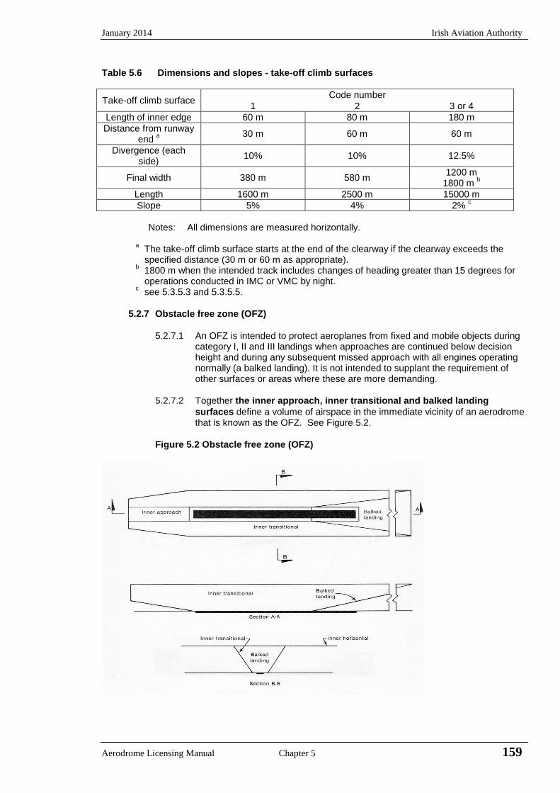
January 2014 Irish Aviation Authority
Aerodrome Licensing Manual Chapter 5 159
Table 5.6 Dimensions and slopes - take-off climb surfaces
Take-off climb surface Code number
1 2 3 or 4
Length of inner edge 60 m 80 m 180 m
Distance from runway end
a
30 m 60 m 60 m
Divergence (each side)
10% 10% 12.5%
Final width 380 m 580 m 1200 m
1800 m b
Length 1600 m 2500 m 15000 m
Slope 5% 4% 2% c
Notes: All dimensions are measured horizontally.
a The take-off climb surface starts at the end of the clearway if the clearway exceeds the
specified distance (30 m or 60 m as appropriate). b 1800 m when the intended track includes changes of heading greater than 15 degrees for
operations conducted in IMC or VMC by night. c see 5.3.5.3 and 5.3.5.5.
5.2.7 Obstacle free zone (OFZ)
5.2.7.1 An OFZ is intended to protect aeroplanes from fixed and mobile objects during
category I, II and III landings when approaches are continued below decision height and during any subsequent missed approach with all engines operating normally (a balked landing). It is not intended to supplant the requirement of other surfaces or areas where these are more demanding.
5.2.7.2 Together the inner approach, inner transitional and balked landing
surfaces define a volume of airspace in the immediate vicinity of an aerodrome that is known as the OFZ. See Figure 5.2.
Figure 5.2 Obstacle free zone (OFZ)
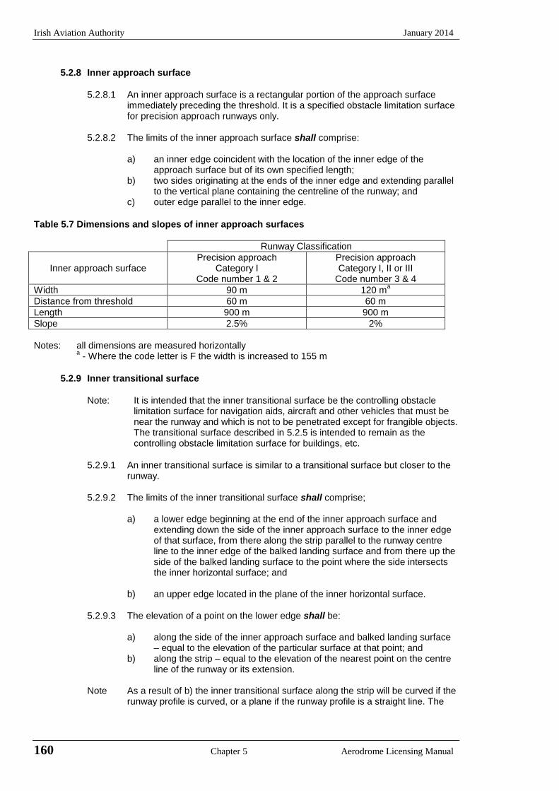
Irish Aviation Authority January 2014
160 Chapter 5 Aerodrome Licensing Manual
5.2.8 Inner approach surface
5.2.8.1 An inner approach surface is a rectangular portion of the approach surface
immediately preceding the threshold. It is a specified obstacle limitation surface for precision approach runways only.
5.2.8.2 The limits of the inner approach surface shall comprise:
a) an inner edge coincident with the location of the inner edge of the
approach surface but of its own specified length; b) two sides originating at the ends of the inner edge and extending parallel
to the vertical plane containing the centreline of the runway; and c) outer edge parallel to the inner edge.
Table 5.7 Dimensions and slopes of inner approach surfaces
Runway Classification
Inner approach surface Precision approach
Category I Code number 1 & 2
Precision approach Category I, II or III
Code number 3 & 4
Width 90 m 120 ma
Distance from threshold 60 m 60 m
Length 900 m 900 m
Slope 2.5% 2%
Notes: all dimensions are measured horizontally
a - Where the code letter is F the width is increased to 155 m
5.2.9 Inner transitional surface
Note: It is intended that the inner transitional surface be the controlling obstacle
limitation surface for navigation aids, aircraft and other vehicles that must be near the runway and which is not to be penetrated except for frangible objects. The transitional surface described in 5.2.5 is intended to remain as the controlling obstacle limitation surface for buildings, etc.
5.2.9.1 An inner transitional surface is similar to a transitional surface but closer to the
runway.
5.2.9.2 The limits of the inner transitional surface shall comprise;
a) a lower edge beginning at the end of the inner approach surface and extending down the side of the inner approach surface to the inner edge of that surface, from there along the strip parallel to the runway centre line to the inner edge of the balked landing surface and from there up the side of the balked landing surface to the point where the side intersects the inner horizontal surface; and
b) an upper edge located in the plane of the inner horizontal surface.
5.2.9.3 The elevation of a point on the lower edge shall be:
a) along the side of the inner approach surface and balked landing surface – equal to the elevation of the particular surface at that point; and
b) along the strip – equal to the elevation of the nearest point on the centre line of the runway or its extension.
Note As a result of b) the inner transitional surface along the strip will be curved if the
runway profile is curved, or a plane if the runway profile is a straight line. The
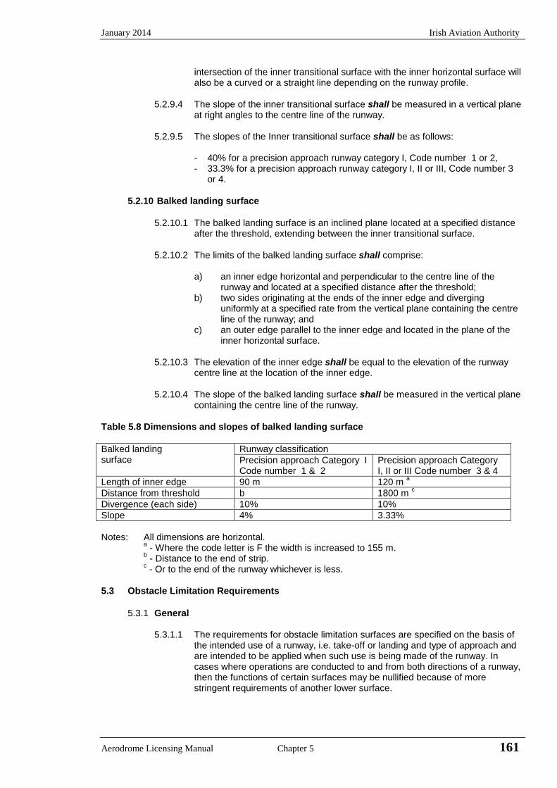
January 2014 Irish Aviation Authority
Aerodrome Licensing Manual Chapter 5 161
intersection of the inner transitional surface with the inner horizontal surface will also be a curved or a straight line depending on the runway profile.
5.2.9.4 The slope of the inner transitional surface shall be measured in a vertical plane at right angles to the centre line of the runway.
5.2.9.5 The slopes of the Inner transitional surface shall be as follows:
- 40% for a precision approach runway category I, Code number 1 or 2, - 33.3% for a precision approach runway category I, II or III, Code number 3
or 4.
5.2.10 Balked landing surface
5.2.10.1 The balked landing surface is an inclined plane located at a specified distance after the threshold, extending between the inner transitional surface.
5.2.10.2 The limits of the balked landing surface shall comprise:
a) an inner edge horizontal and perpendicular to the centre line of therunway and located at a specified distance after the threshold;
b) two sides originating at the ends of the inner edge and diverginguniformly at a specified rate from the vertical plane containing the centreline of the runway; and
c) an outer edge parallel to the inner edge and located in the plane of theinner horizontal surface.
5.2.10.3 The elevation of the inner edge shall be equal to the elevation of the runway centre line at the location of the inner edge.
5.2.10.4 The slope of the balked landing surface shall be measured in the vertical plane containing the centre line of the runway.
Table 5.8 Dimensions and slopes of balked landing surface
Balked landing
surface
Runway classification
Precision approach Category I Code number 1 & 2
Precision approach Category I, II or III Code number 3 & 4
Length of inner edge 90 m 120 m a
Distance from threshold b 1800 m c
Divergence (each side) 10% 10%
Slope 4% 3.33%
Notes: All dimensions are horizontal. a - Where the code letter is F the width is increased to 155 m.
b - Distance to the end of strip.
c - Or to the end of the runway whichever is less.
5.3 Obstacle Limitation Requirements
5.3.1 General
5.3.1.1 The requirements for obstacle limitation surfaces are specified on the basis of the intended use of a runway, i.e. take-off or landing and type of approach and are intended to be applied when such use is being made of the runway. In cases where operations are conducted to and from both directions of a runway, then the functions of certain surfaces may be nullified because of more stringent requirements of another lower surface.
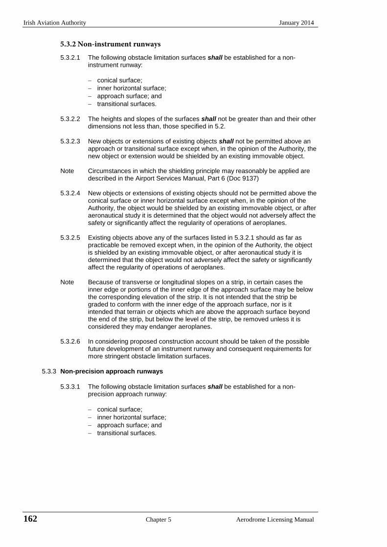
Irish Aviation Authority January 2014
162 Chapter 5 Aerodrome Licensing Manual
5.3.2.1 The following obstacle limitation surfaces shall be established for a non-instrument runway:
conical surface;
inner horizontal surface;
approach surface; and
transitional surfaces.
5.3.2.2 The heights and slopes of the surfaces shall not be greater than and their other dimensions not less than, those specified in 5.2.
5.3.2.3 New objects or extensions of existing objects shall not be permitted above an approach or transitional surface except when, in the opinion of the Authority, the new object or extension would be shielded by an existing immovable object.
Note Circumstances in which the shielding principle may reasonably be applied are described in the Airport Services Manual, Part 6 (Doc 9137)
5.3.2.4 New objects or extensions of existing objects should not be permitted above the conical surface or inner horizontal surface except when, in the opinion of the Authority, the object would be shielded by an existing immovable object, or after aeronautical study it is determined that the object would not adversely affect the safety or significantly affect the regularity of operations of aeroplanes.
5.3.2.5 Existing objects above any of the surfaces listed in 5.3.2.1 should as far as practicable be removed except when, in the opinion of the Authority, the object is shielded by an existing immovable object, or after aeronautical study it is determined that the object would not adversely affect the safety or significantly affect the regularity of operations of aeroplanes.
Note Because of transverse or longitudinal slopes on a strip, in certain cases the inner edge or portions of the inner edge of the approach surface may be below the corresponding elevation of the strip. It is not intended that the strip be graded to conform with the inner edge of the approach surface, nor is it intended that terrain or objects which are above the approach surface beyond the end of the strip, but below the level of the strip, be removed unless it is considered they may endanger aeroplanes.
5.3.2.6 In considering proposed construction account should be taken of the possible future development of an instrument runway and consequent requirements for more stringent obstacle limitation surfaces.
5.3.3 Non-precision approach runways
5.3.3.1 The following obstacle limitation surfaces shall be established for a non-precision approach runway:
conical surface;
inner horizontal surface;
approach surface; and
transitional surfaces.
5.3.2 Non-instrument runways
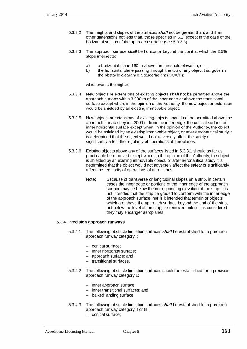
January 2014 Irish Aviation Authority
Aerodrome Licensing Manual Chapter 5 163
5.3.3.2 The heights and slopes of the surfaces shall not be greater than, and their other dimensions not less than, those specified in 5.2, except in the case of the horizontal section of the approach surface (see 5.3.3.3).
5.3.3.3 The approach surface shall be horizontal beyond the point at which the 2.5%
slope intersects:
a) a horizontal plane 150 m above the threshold elevation; or b) the horizontal plane passing through the top of any object that governs
the obstacle clearance altitude/height (OCA/H); whichever is the higher.
5.3.3.4 New objects or extensions of existing objects shall not be permitted above the approach surface within 3 000 m of the inner edge or above the transitional surface except when, in the opinion of the Authority, the new object or extension would be shielded by an existing immovable object.
5.3.3.5 New objects or extensions of existing objects should not be permitted above the
approach surface beyond 3000 m from the inner edge, the conical surface or inner horizontal surface except when, in the opinion of the Authority, the object would be shielded by an existing immovable object, or after aeronautical study it is determined that the object would not adversely affect the safety or significantly affect the regularity of operations of aeroplanes.
5.3.3.6 Existing objects above any of the surfaces listed in 5.3.3.1 should as far as
practicable be removed except when, in the opinion of the Authority, the object is shielded by an existing immovable object, or after aeronautical study it is determined that the object would not adversely affect the safety or significantly affect the regularity of operations of aeroplanes.
Note: Because of transverse or longitudinal slopes on a strip, in certain
cases the inner edge or portions of the inner edge of the approach surface may be below the corresponding elevation of the strip. It is not intended that the strip be graded to conform with the inner edge of the approach surface, nor is it intended that terrain or objects which are above the approach surface beyond the end of the strip, but below the level of the strip, be removed unless it is considered they may endanger aeroplanes.
5.3.4 Precision approach runways
5.3.4.1 The following obstacle limitation surfaces shall be established for a precision approach runway category I:
conical surface;
inner horizontal surface;
approach surface; and
transitional surfaces.
5.3.4.2 The following obstacle limitation surfaces should be established for a precision approach runway category 1:
inner approach surface;
inner transitional surfaces; and
balked landing surface.
5.3.4.3 The following obstacle limitation surfaces shall be established for a precision approach runway category II or III:
conical surface;
Irish Aviation Authority January 2014
164 Chapter 5 Aerodrome Licensing Manual
inner horizontal surface;
approach surface and inner approach surface;
transitional surfaces;
inner transitional surfaces; and
balked landing surface.
5.3.4.4 The heights and slopes of the surfaces shall not be greater than, and their other dimensions not less than, those specified in 5.2 except in the case of the horizontal section of the approach surface (see 5.3.4.5).
5.3.4.5 The approach surface shall be horizontal beyond the point at which the 2.5%
slope intersects:
a) a horizontal plane 150 m above the threshold elevation; or b) the horizontal plane passing through the top of any object that governs
the obstacle clearance limit; whichever is the higher.
5.3.4.6 Fixed objects shall not be permitted above the inner approach surface, the inner transitional surface or the balked landing surface (i.e. the OFZ) except for frangible objects which because of their function must be located on the strip. Mobile objects shall not be permitted above these surfaces during the use of the runway for landing.
5.3.4.7 New objects or extensions of existing objects shall not be permitted above an
approach surface or a transitional surface except when, in the opinion of the Authority, the new object or extension would be shielded by an existing immovable object.
5.3.4.8 New objects or extensions of existing objects should not be permitted above the
conical surface and inner horizontal surface except when, in the opinion of the Authority, the object would be shielded by an existing immovable object, or after aeronautical study it is determined that the object would not adversely affect the safety or significantly affect the regularity of operations of aeroplanes.
5.3.4.9 Existing objects above an approach surface, a transitional surface, the conical
surface and inner horizontal surface should as far as practicable be removed except when, in the opinion of the Authority, the object is shielded by an existing immovable object, or after aeronautical study it is determined that the object would not adversely affect the safety or significantly affect the regularity of operations of aeroplanes.
Note Because of transverse or longitudinal slopes on a strip, in certain cases the
inner edge or portions of the inner edge of the approach surface may be below the corresponding elevation of the strip. It is not intended that the strip be graded to conform with the inner edge of the approach surface, not is it intended that terrain or objects which are above the approach surface beyond the end of the strip, but below the level of the strip, be removed unless it is considered they may endanger aeroplanes.
January 2014 Irish Aviation Authority
Aerodrome Licensing Manual Chapter 5 165
5.3.5 Runways used for take-off
5.3.5.1 The following obstacle limitation surface shall be established for a runway meant for take-off:
take-off climb surface.
5.3.5.2 The dimensions of the surface shall not be less than the dimensions specified in Table 5.6 except that a lesser length may be adopted for the take-off climb surface where such lesser length would be consistent with procedural measures adopted to govern the outward flight of aeroplanes.
5.3.5.3 The operational characteristics of aeroplanes for which the runway is intended
should be examined to see if it is desirable to reduce the slope specified in Table 5.6 when critical operating conditions are to be catered to. If the specified slope is reduced, corresponding adjustment to the length of the take-off climb surface should be made so as to provide protection to a height of 300 m.
Note When local conditions differ widely from sea level standard atmospheric
conditions, it may be advisable for the slope specified in Table 5.6 to be reduced. The degree of this reduction depends on the divergence between local conditions and sea level standard atmospheric conditions, and on the performance characteristics and operational requirements of the aeroplanes for which the runway is intended.
5.3.5.4 New objects or extensions of existing objects shall not be permitted above a
take-off climb surface except when in the opinion of the Authority the new object or extension would be shielded by an existing immovable object.
5.3.5.5 If no object reaches the 2% (1:50) take-off climb surface, new objects should be
limited to preserve the existing obstacle free surface or a surface down to a slope of 1.6 % (1:62.5).
5.3.5.6 Existing objects that extend above the take-off climb surface should as far as
practicable be removed except when, in the opinion of the Authority, the object is shielded by an existing immovable object, or after aeronautical study it is determined that the object would not adversely affect the safety or significantly affect the regularity of operations of aeroplanes.
Note Because of transverse slopes on a strip or clearway, in certain cases portions of
the inner edge of the take-off climb surface may be below the corresponding elevation of the strip or clearway. It is not intended that the strip or clearway be graded to conform with the inner edge of the take-off climb surface, nor is it intended that terrain or objects which are above the take-off climb surface beyond the end of the strip or clearway, but below the level of the strip or clearway, be removed unless it is considered they may endanger aeroplanes. Similar considerations apply at the junction of a clearway and strip where differences in transverse slopes exist.
5.3.6 Outer horizontal surface 5.3.6.1 An outer horizontal surface should be established for an aerodrome where the
code number is 2, 3, or 4.
Note See also 5.2.1
5.3.6.2 It is particularly desirable to review carefully any proposal to erect high masts or
other skeletal structures in areas which would otherwise be suitable for use by aircraft on wide visual circuits, or arrival routes towards the aerodrome or circuit, or on departure or missed approach climb paths. Avoidance by marking
Irish Aviation Authority January 2014
166 Chapter 5 Aerodrome Licensing Manual
or lighting cannot always be relied upon in view of the relatively inconspicuous character of these structures.
5.3.6.3 Existing objects, within the area of the outer horizontal surface should as far as
practicable be removed if they are both higher than 30 m above the local ground level and higher than the outer horizontal surface, except when in the opinion of the Authority the object is shielded by an existing immovable object, or after an aeronautical study it is determined that the objects would not adversely affect the safety or significantly affect the regularity of operations of aeroplanes.
5.3.6.4 Extensions of existing objects, or new objects within the area of the outer
horizontal surface should not be permitted if they are both higher than 30 m above the local ground level and higher than the outer horizontal surface, except when in the opinion of the Authority the object is shielded by an existing immovable object, or after an aeronautical study it is determined that the objects would not adversely affect the safety or significantly affect the regularity of operations of aeroplanes.
5.3.7 Other objects
5.3.7.1 Objects which do not project through the approach surface but which would nevertheless adversely affect the optimum siting or performance of visual or non visual aids should, as far as practicable, be removed.
5.3.7.2 Anything which may, in the opinion of the Authority after aeronautical study,
endanger aeroplanes on the movement area or in the air within the limits of the inner horizontal and conical surfaces should be regarded as an obstacle and should be removed in so far as practicable.
Note In certain circumstances, objects that do not project above any of the obstacle
limitation surfaces may constitute a hazard to aeroplanes as, for example, where there are one or more isolated objects in the vicinity of an aerodrome.
5.3.8 Objects outside aerodrome obstacle limitation surfaces
(En-route obstacles)
5.3.8.1 For obstacles located beyond the limits of the obstacle limitation surfaces of an
aerodrome, reference should be made to the Irish Aviation Authority Order S.I. 423 of 1999 (En Route Obstacles to Air Navigation) as well as S.I. 215 of 1997 (Obstacles to Aircraft in Flight).
5.3.8.2 Arrangements should be made to enable the appropriate authority to be
consulted concerning proposed construction beyond the limits of the obstacle limitation surfaces that extend above a height established by that authority, in order to permit an aeronautical study of the effect of such constriction on the operation of aeroplanes.
5.3.8.3 In areas beyond the limits of the obstacle limitation surfaces, at least those
objects which extend to a height of 150 m or more above ground elevation should be regarded as obstacles, unless a social aeronautical study indicates that they do not constitute a hazard to aeroplanes.
Note This study may have regard to the nature of operations concerned and may
distinguish between day and night operations.

January 2014 Irish Aviation Authority
Aerodrome Licensing Manual Chapter 5 167
5.3.9 Shielding
5.3.9.1 The principle of shielding is employed to permit a more logical approach to
restricting new construction and prescribing obstacle marking and lighting. Shielding principles are applied when some object, an existing building or natural terrain, already penetrates above one of the obstacle limitation surfaces described. If it is considered by the Authority that the nature of the object is such that its presence may be described as permanent, then additional objects within a specified area around it may be permitted to penetrate the surface without being considered as obstacles. The original obstacle is considered as dominating or shielding the surrounding area. No obstacle can be considered as shielded if it is closer to the runway than the shielding obstacle. At other locations, in the application of the shielding principle the Authority will follow the guidance presented in the Airport Services Manual, Part 6 (Doc 9137) supported by an aeronautical study.
5.3.10 Safeguarding
5.3.10.1 The design and operation of aerodromes should take into account, where
appropriate, land use and environmental control measures. Guidance on this matter is given in sections 5.3.10 to 5.3.12 inclusive and is contained in Airport Planning Manual Part 2 (Doc 9184).
5.3.10.2 The requirement for land use planning in the vicinity of an aerodrome is twofold,
namely;
a) to provide for aerodrome needs e.g. obstacle limitation areas and future aerodrome development; and
b) to ensure minimal interference to the environment and to the public (see
Airport Planning Manual, Part 2, Doc 9184). 5.3.10.3 It will be evident that the position, height and nature of obstacles in and near the
take-off and approach paths to an runway and on the aerodrome itself determine to a large extent the distances declared for take-off and landing, the approval for the use of a runway for instrument approaches, the obstacle clearance limits associated with such procedures and the location of visual and electronic aids to navigation.
5.3.10.4 In a Notice to Aerodrome Licence Holders (T.02) issued under the Air
Navigation (Aerodromes and Visual Ground Aids) Order the Authority has directed that for aerodromes licensed for public use ‘Aerodrome Safeguarding Maps’, based on the requirements described hereunder, be prepared by the aerodrome authority and copies lodged with the Authority and with the Local Authority responsible for dealing with planning applications in the vicinity of the aerodrome concerned.
5.3.10.5 For aerodromes licensed for public use, the aerodrome authority shall monitor
the relevant local authority planning lists to identify all proposed construction of objects (within a radial distance of 15 km from the aerodrome reference point for aerodromes whose reference code is 3 or 4 and 10 km for the smaller aerodromes) where the potential exists for conflict with obstacle limitation requirements and the requirements described hereunder. The aerodrome authority shall make their concerns known to the Local Planning Authority within the permitted timescale for making a submission.
5.3.10.6 Operators of licensed aerodromes which are not subject to the safeguarding
direction and operators of unlicensed aerodromes and sites for other aviation activities (e.g. gliding or parachuting) should take steps to protect their locations
Irish Aviation Authority January 2014
168 Chapter 5 Aerodrome Licensing Manual
by establishing an agreed consultation procedure between themselves and the planning authorities.
5.3.10.7 The Authority is available to give advice, on request, to an aerodrome authority
in the preparation of a safeguarding map.
5.3.11 The aerodrome safeguarding map
5.3.11.1 Depending on the aerodrome reference code and runway classification, the following should be illustrated on a runway safeguarding map;
a) a contoured chart of the “obstacle limitation surfaces appropriate to the
aerodrome reference code number and runway classification either existing or planned;
b) the location and height of all existing objects or terrain which infringe the obstacle limitation surfaces;
Note If the aerodrome reference code number is 3 or 4 a 1% and 2% take-off climb
surface should be shown on the safeguarding map. This will be supported with the request that all proposed new objects or extensions of existing objects above the 1% slope or adjacent to the periphery will be referred to the licensee of the aerodrome concerned for comment. The purpose of this is to ensure that any proposed new objects under the take-off climb surface, even if below the 2% slope, will not impose a take-off weight penalty for aeroplanes normally using the aerodrome.
c) the visual approach slope indicator system obstacle protection surface(s); d) the location and height of any existing objects or terrain which infringe
those surface(s). e) the approach light plane(s); and f) bird hazard areas within a distance of 13 km from each active runway (8
km for aerodromes with no runway greater than 1200 m. in length). g) Laser beam free zones
5.3.12 Dangerous and confusing lights
5.3.12.1 A non-aeronautical ground light near an aerodrome which might endanger the
safety of aircraft shall be extinguished, screened or otherwise modified so as to eliminate the source of danger.
5.3.12.2 To protect the safety of aircraft against the hazardous effects of laser emitters,
the following protected zones should be established around aerodromes:
a laser-beam free flight zone (LFFZ)
a laser-beam critical flight zone (LCFZ)
a laser-beam sensitive flight zone (LSFZ)
Notes: 1. Figures 5.3, 5.4 and 5.5 be used to determine the exposure levels and distances that adequately protect flight operations.
2. The restrictions on the use of laser beams in the three protected flight zones, LFFZ, LCFZ and LSFZ, refer to visible laser beams only. Laser emitters operated by the authorities in a manner compatible with flight safety are excluded. In all navigable airspace the irradiance level of any laser beam, visible or invisible, is expected to be less than or equal to the maximum permissible exposure (MPE) unless such emission has been notified to the authority and permission obtained.
3. The protected flight zones are established in order to mitigate the risk of operating laser emitters in the vicinity of aerodromes.
4. Further guidance on how to protect flight operations form the hazardous effects of laser emitters is contained in the Manual on Laser Emitters and
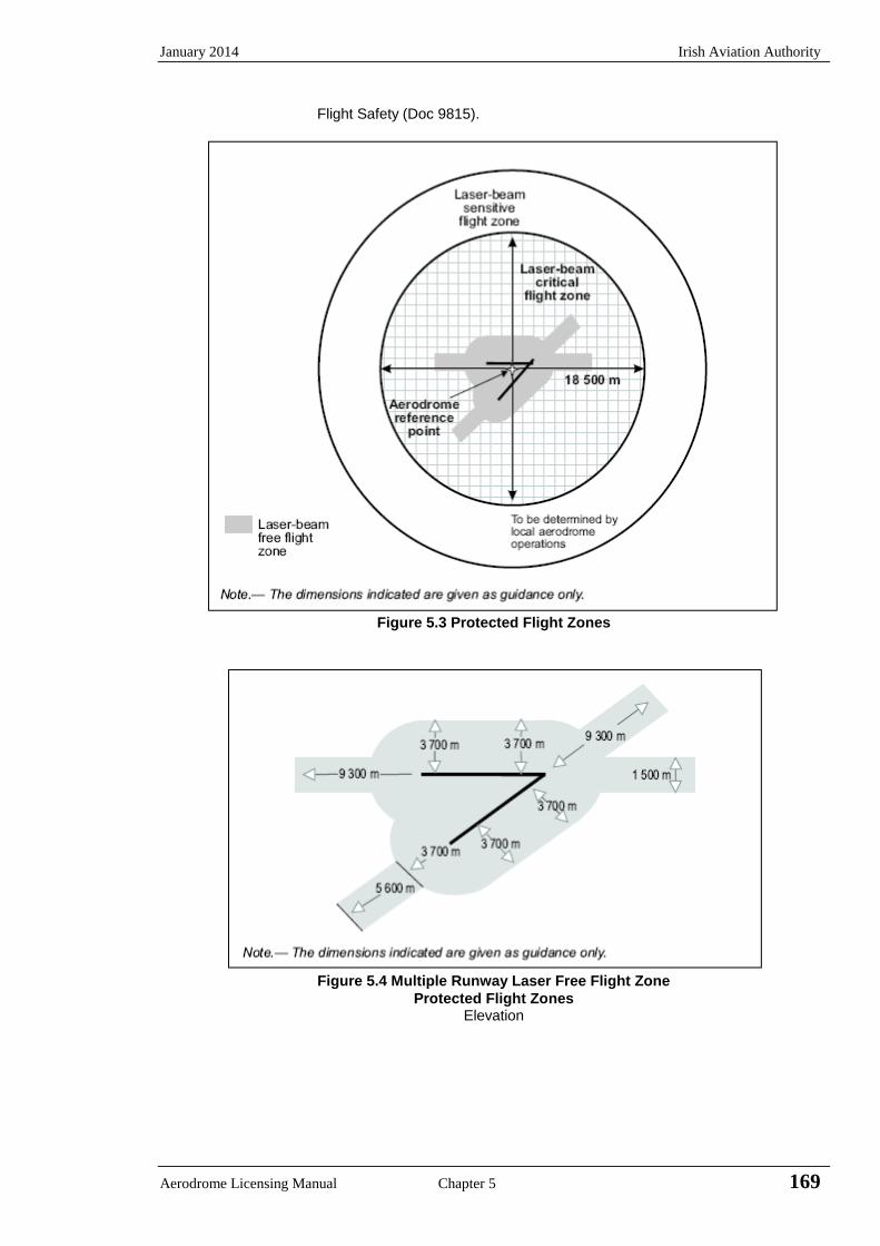
January 2014 Irish Aviation Authority
Aerodrome Licensing Manual Chapter 5 169
Flight Safety (Doc 9815).
Figure 5.3 Protected Flight Zones
Figure 5.4 Multiple Runway Laser Free Flight Zone
Protected Flight Zones Elevation
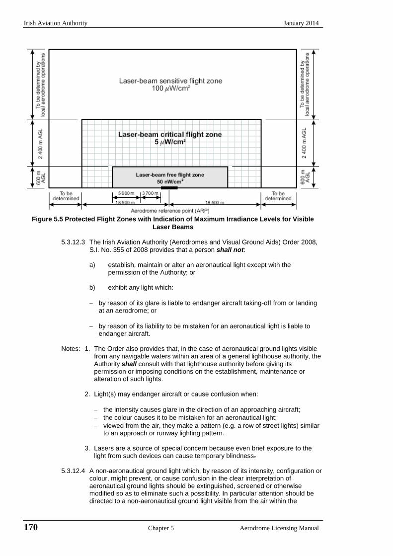
Irish Aviation Authority January 2014
170 Chapter 5 Aerodrome Licensing Manual
Figure 5.5 Protected Flight Zones with Indication of Maximum Irradiance Levels for Visible
Laser Beams
5.3.12.3 The Irish Aviation Authority (Aerodromes and Visual Ground Aids) Order 2008, S.I. No. 355 of 2008 provides that a person shall not:
a) establish, maintain or alter an aeronautical light except with the
permission of the Authority; or
b) exhibit any light which:
by reason of its glare is liable to endanger aircraft taking-off from or landing at an aerodrome; or
by reason of its liability to be mistaken for an aeronautical light is liable to endanger aircraft.
Notes: 1. The Order also provides that, in the case of aeronautical ground lights visible
from any navigable waters within an area of a general lighthouse authority, the Authority shall consult with that lighthouse authority before giving its permission or imposing conditions on the establishment, maintenance or alteration of such lights.
2. Light(s) may endanger aircraft or cause confusion when:
the intensity causes glare in the direction of an approaching aircraft;
the colour causes it to be mistaken for an aeronautical light;
viewed from the air, they make a pattern (e.g. a row of street lights) similar to an approach or runway lighting pattern.
3. Lasers are a source of special concern because even brief exposure to the
light from such devices can cause temporary blindness.
5.3.12.4 A non-aeronautical ground light which, by reason of its intensity, configuration or colour, might prevent, or cause confusion in the clear interpretation of aeronautical ground lights should be extinguished, screened or otherwise modified so as to eliminate such a possibility. In particular attention should be directed to a non-aeronautical ground light visible from the air within the
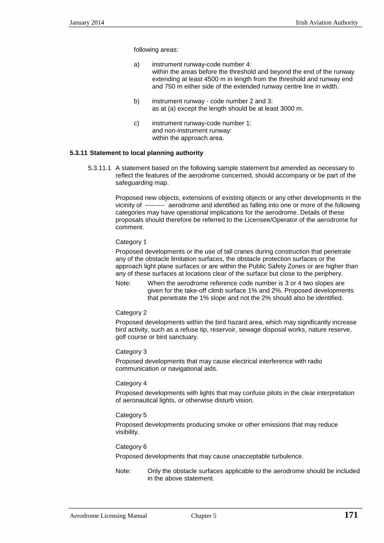
January 2014 Irish Aviation Authority
Aerodrome Licensing Manual Chapter 5 171
following areas:
a) instrument runway-code number 4: within the areas before the threshold and beyond the end of the runway extending at least 4500 m in length from the threshold and runway end and 750 m either side of the extended runway centre line in width.
b) instrument runway - code number 2 and 3:
as at (a) except the length should be at least 3000 m.
c) instrument runway-code number 1: and non-instrument runway: within the approach area.
5.3.11 Statement to local planning authority
5.3.11.1 A statement based on the following sample statement but amended as necessary to
reflect the features of the aerodrome concerned, should accompany or be part of the safeguarding map.
Proposed new objects, extensions of existing objects or any other developments in the vicinity of --------- aerodrome and identified as falling into one or more of the following categories may have operational implications for the aerodrome. Details of these proposals should therefore be referred to the Licensee/Operator of the aerodrome for comment.
Category 1
Proposed developments or the use of tall cranes during construction that penetrate any of the obstacle limitation surfaces, the obstacle protection surfaces or the approach light plane surfaces or are within the Public Safety Zones or are higher than any of these surfaces at locations clear of the surface but close to the periphery.
Note: When the aerodrome reference code number is 3 or 4 two slopes are given for the take-off climb surface 1% and 2%. Proposed developments that penetrate the 1% slope and not the 2% should also be identified.
Category 2
Proposed developments within the bird hazard area, which may significantly increase bird activity, such as a refuse tip, reservoir, sewage disposal works, nature reserve, golf course or bird sanctuary.
Category 3
Proposed developments that may cause electrical interference with radio communication or navigational aids.
Category 4
Proposed developments with lights that may confuse pilots in the clear interpretation of aeronautical lights, or otherwise disturb vision.
Category 5
Proposed developments producing smoke or other emissions that may reduce visibility.
Category 6
Proposed developments that may cause unacceptable turbulence.
Note: Only the obstacle surfaces applicable to the aerodrome should be included in the above statement.
Irish Aviation Authority January 2014
172 Chapter 5 Aerodrome Licensing Manual
5.3.12 Additional protection
5.3.12.1 It is recommended that the licensee acquire property rights to the lands for the first 1000m from the runway thresholds. The purpose of this is to allow the licensee unrestricted access for the erection, maintenance and security of approach lighting, the maintenance of the approach lighting plane, access for rescue and firefighting vehicles and the establishment of a Runway End Safety Area.
5.4 Visual Aids for Denoting Obstacles
5.4.1 General
5.4.1.1 The following paragraphs contain details of the general requirements for the marking and lighting of obstacles on or near aerodromes and objects which the Authority has deemed to be en-route obstacles.
Note: The marking and /or lighting of obstacles is intended to reduce
hazards to aircraft by indicating the presence of the obstacles. It does not necessarily reduce operating limitations that may be imposed by an obstacle. The Authority, in the pursuit of aviation safety, may require the marking and/or lighting of any object.
5.4.1.2 The responsibility for marking and lighting obstacles on and near aerodromes
must be determined between the aerodrome authority and the owners of the structures. The Authority is not concerned with the allocation of responsibility but may impose additional operating restrictions on the airport if the requirements for lighting and/or marking are not met.
5.4.1.3 The aerodrome authority is responsible for ensuring that all obstacles on the
movement area are lighted and /or marked as required, irrespective of ownership.
5.4.2 Objects to be marked and/or lighted
5.4.2.1 A fixed obstacle that extends above a take-off climb surface within 3000 m of
the inner edge of the take-off climb surface should be marked and if the runway is used at night lighted except that:
a) such marking and lighting may be omitted when the obstacle is shielded
by another fixed obstacle; b) the marking may be omitted when the obstacle is lighted by medium
intensity obstacle lights, Type A, by day and its height above the level of the surrounding ground does not exceed 150 m; and
c) the marking may be omitted when the obstacle is lighted by high intensity obstacle lights by day.
d) the lighting may be omitted where the obstacle is a lighthouse and an aeronautical study indicates the lighthouse light to be sufficient.
5.4.2.2 A fixed object, other than an obstacle, adjacent to a take-off climb surface
should be marked and, if the runway is used at night lighted if such marking and lighting is considered necessary to ensure its avoidance, except that marking may be omitted when: a) the object is lighted by medium intensity obstacle lights, Type A, by day
and its height above the level of the surrounding ground does not exceed 150 m; or
b) the object is lighted by high intensity obstacle lights by day.
January 2014 Irish Aviation Authority
Aerodrome Licensing Manual Chapter 5 173
5.4.2.3 A fixed obstacle that extends above an approach or transitional surface within 3000 m of the inner edge of the approach surface shall be marked and if the runway is used at night lighted except that:
a) such marking and lighting may be omitted when the obstacle is shielded
by another fixed obstacle; b) the marking may be omitted when the obstacle is lighted by medium
intensity obstacle lights, Type A, by day and its height above the level of the surrounding ground does not exceed 150 m; and
c) the marking may be omitted when the obstacle is lighted by high intensity obstacle lights by day.
d) the lighting may be omitted where the obstacle is a lighthouse and an aeronautical study indicates the lighthouse light to be sufficient.
5.4.2.4 A fixed obstacle above a horizontal surface should be marked and, if the
aerodrome is used at night, lighted except that:
a) such marking and lighting may be omitted when:
(1) the obstacle is shielded by another fixed obstacle; or (2) for a circuit extensively obstructed by immovable objects or terrain,
procedures have been established to ensure safe vertical clearance below prescribed flight paths; or
(3) an aeronautical study shows the obstacle not to be of operational significance.
b) marking may be omitted when the obstacle is lighted by medium intensity
obstacle lights, Type A, by day and its height above the level of the surrounding ground does not exceed 150 m; and
c) marking may be omitted when the obstacle is lighted by high intensity obstacle lights by day.
d) the lighting may be omitted where the obstacle is a lighthouse and an aeronautical study indicates the lighthouse light to be sufficient.
5.4.2.5 A fixed object that extends above an obstacle protection surface for a visual
approach slope indicator system shall be marked and, if the runway is used at night, lighted.
Note: See 3.5.4 for information on the obstacle protection surface.
5.4.2.6 Following an aeronautical study the Authority may specify requirements
concerning the marking and/or lighting of obstacles, within the area of the outer horizontal surface.
5.4.2.7 Vehicles and other mobile objects, excluding aircraft, on the movement area of
an aerodrome are obstacles and shall be marked and, if the vehicles and aerodrome are used at night or in conditions of low visibility, lighted, except that aircraft servicing equipment and vehicles used only on aprons may be exempt.
5.4.2.8 Elevated aeronautical ground lights within the movement area shall be marked
so as to be conspicuous by day. Obstacle lights shall not be installed on elevated ground lights or signs on the movement area.
5.4.2.9 All obstacles within the distance specified in Table 2.8 column 11 or 12, from
the centre line of a taxiway, apron taxiway or aircraft stand taxilane shall be marked and, if the taxiway, apron taxiway or aircraft stand taxilane is used at night, lighted.
5.4.2.10 Objects that in accordance with 5.3.8 are deemed by the Authority to be en-
route obstacles should be marked and lighted, except that the marking may be omitted when the obstacle is lighted by high-intensity obstacle lights by day.

Irish Aviation Authority January 2014
174 Chapter 5 Aerodrome Licensing Manual
5.4.2.11 Overhead wires, cables, etc. crossing a river, valley or highway identified as obstacles should be marked and their supporting towers marked and lighted if an aeronautical study indicates that the wires or cables could constitute a hazard to aircraft except that the marking of the supporting towers may be omitted when they are lighted by high-intensity obstacle lights by day.
5.4.2.12 When it has been determined that an overhead wire, cable, etc., needs to be
marked but it is not practicable to install markers on the wire, cable, etc., then high-intensity obstacle lights, Type B, should be provided on the supporting towers.
5.4.3 Marking of objects
5.4.3.1 All fixed objects to be marked shall whenever practicable be coloured, but if this is not practicable, markers or flags shall be displayed on or above them, except that objects that are sufficiently conspicuous by their shape, size or colour need not be otherwise marked.
5.4.3.2 All mobile objects to be marked shall be coloured or display flags.
5.4.3.3 An object should be coloured to show a chequered pattern if it has essentially
unbroken surfaces and its projection on any vertical plane equals or exceeds 4.5 m in both dimensions. The pattern should consist of rectangles of not less than 1.5 m and not more than 3 m on a side, the corners being of the darker colour. The colours of the pattern should contrast each with the other and with the background with which they will be seen. Orange and white or alternatively red and white should be used, except where such colours merge with the background. (See Figure 5.6).
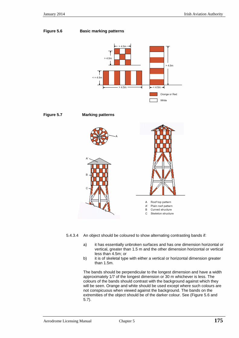
January 2014 Irish Aviation Authority
Aerodrome Licensing Manual Chapter 5 175
Figure 5.6 Basic marking patterns
Figure 5.7 Marking patterns
5.4.3.4 An object should be coloured to show alternating contrasting bands if:
a) it has essentially unbroken surfaces and has one dimension horizontal or
vertical, greater than 1.5 m and the other dimension horizontal or vertical less than 4.5m; or
b) it is of skeletal type with either a vertical or horizontal dimension greater than 1.5m.
The bands should be perpendicular to the longest dimension and have a width
approximately 1/7 of the longest dimension or 30 m whichever is less. The colours of the bands should contrast with the background against which they will be seen. Orange and white should be used except where such colours are not conspicuous when viewed against the background. The bands on the extremities of the object should be of the darker colour. See (Figure 5.6 and 5.7).

Irish Aviation Authority January 2014
176 Chapter 5 Aerodrome Licensing Manual
Note Table 5.9 shows a formula for determining band width and for having an odd number of bands, thus permitting both the top and bottom bands to be of the darker colour.
5.4.3.5 An object should be coloured in a single conspicuous colour if its projection on
any vertical plane has both dimensions less than 1.5 m. Orange or red should be used, except where such colours merge with the background.
Note Against some backgrounds it may be found necessary to use a different colour
from orange or red to obtain sufficient contrast.
Table 5.9 Marking band widths
Longest dimension Band width
Greater than not exceeding
1.5 m 210 m 1/7 of longest dimension
210 m 270 m 1/9 “
270 m 330 m 1/11 “
330 m 390 m 1/13 “
390 m 450 m 1/15 “
450 m 510 m 1/17 “
510 m 570 m 1/19 “
570 m 630 m 1/21 “
5.4.3.6 When mobile objects are marked by colour, a single conspicuous colour, preferably red or yellowish green for emergency vehicles and yellow for service vehicles should be used.
5.4.3.7 Markers displayed on or adjacent to objects shall be located in conspicuous
positions so as to retain the general definition of the object and shall be recognisable in clear weather from a distance of at least 1000 m for an object to be viewed from the air and 300 m for an object to be viewed from the ground in all directions in which the aircraft is likely to approach the object. The shape of markers shall be distinctive to the extent necessary to ensure that they are not mistaken for markers employed to convey other information, and they shall be such that the hazard presented by the object they mark is not increased.
5.4.3.8 A marker displayed on an overhead wire, cable, etc., should be spherical and
have a diameter not less than 60 cm.
5.4.3.9 The spacing between two consecutive markers or between a marker and a supporting tower should be appropriate to the diameter of the marker, but in no case should the spacing exceed:
a) 30 m where the marker diameter is 60 cm progressively increasing with
the diameter of the marker to, b) 35 m where the marker diameter is 80 cm and further progressively
increasing to a maximum of, c) 40 m where the marker diameter is at least 130 cm.
Where multiple wires, cables, etc. are involved a marker should be located not lower than the level of the highest wire at the point marked.
5.4.3.10 A marker should be of one colour. When installed, white and red or white and
orange markers should be displayed alternately. The colour selected should contrast with the background against which it will be seen.
January 2014 Irish Aviation Authority
Aerodrome Licensing Manual Chapter 5 177
5.4.3.11 Flags used to mark objects shall be displayed around, on top of, or around the highest edge of, the object. When flags are used to mark extensive objects or groups of closely spaced objects, they shall be displayed at least every 15 m. Flags shall not increase the hazard presented by the objects they mark.
5.4.3.12 Flags used to mark fixed objects shall not be less than 0.6 m square and flags used to mark mobile objects, not less than 0.9 m square.
5.4.3.13 Flags used to mark fixed objects should be orange in colour or a combination of two triangular sections, one orange and the other white, or one red and the other white, except where such colours merge with the background, other conspicuous colours should be used.
5.4.3.14 Flags used to mark mobile objects shall consist of a chequered pattern, each square having sides of not less than 0.3 m. The colours of the pattern shall contrast each with the other and with the background against which they will be
seen. Orange and white or alternatively red and white shall be used except where such colours merge with the background.
5.4.4 Lighting of objects
5.4.4.1 The presence of objects which must be lighted as specified in 5.4.2 shall be indicated by low, medium or high intensity obstacle lights or a combination of such lights, one of which shall be located as close as practicable to the top of the object.
Note High-intensity obstacle lights are intended for day use as well as night use. Care is needed to ensure that these lights do not create disconcerting dazzle. Guidance on the design, location and operation of high-intensity obstacle lights is given in the Aerodrome Design Manual, Part 4 (Doc 9157).
5.4.4.2 Low intensity obstacle lights, Type A or Type B, should be used where the object is a less extensive one and its height above the surrounding ground is less than 45 m. The type of low intensity obstacle light to use in particular circumstances is as follows:
a) Low-intensity Type A obstacle lights (10 candela minimum, see Table5.11) should be used for obstacles on the movement area or in thevicinity of an aerodrome where low-intensity Type B obstacle lights maycause dazzle to pilots of aircraft and also in areas away from theaerodrome with low levels of background illuminance.
b) Low intensity Type B obstacle lights (32 candela minimum, see Table5.11) should be used in areas on the movement area or in the vicinity ofan aerodrome with high levels of background illuminance and also inareas away from the aerodrome with high levels of backgroundilluminance or where extra conspicuity is required.
5.4.4.3 Where the use of low intensity obstacle lights, Type A or B would be inadequate or an early special warning is required, then medium or high-intensity obstacle lights should be used.
5.4.4.4 Low-intensity obstacle lights, Type C, shall be displayed on vehicles and other mobile objects excluding aircraft.
5.4.4.5 Low-intensity obstacle lights, Type D, shall be displayed on follow me vehicles.
5.4.4.6 Low-intensity obstacle lights, Type B, should be used either alone or in combination with medium intensity obstacle lights, Type B in accordance with 5.4.4.7.
Irish Aviation Authority January 2014
178 Chapter 5 Aerodrome Licensing Manual
5.4.4.7 Medium-intensity obstacle lights, Type A, B, or C, should be used where the object is an extensive one or its height above the level of the surrounding ground is greater than 45 m. Medium-intensity obstacle lights, Type A and C should be used alone, whereas medium-intensity obstacle lights, Type B should be used either alone or in combination with low-intensity obstacle lights, Type B.
Note: A group of trees or buildings is regarded as an extensive object.
5.4.4.8 High-intensity obstacle lights, Type A, should be used to indicate the presence
of an object if its height above the level of the surrounding ground exceeds 150 m and an aeronautical study indicates such lights to be essential for the recognition of the object by day.
5.4.4.9 High intensity obstacle lights, Type B, should be used to indicate the presence
of a tower supporting overhead wires, cables, etc. where:
a) an aeronautical study indicates such lights to be essential for the recognition of the presence of wires; or
b) it has not been found practicable to install markers on the wires, cables, etc.
5.4.4.10 Where, in the opinion of the appropriate authority, the use of high-intensity
obstacle lights, Type A or B, or medium intensity obstacle lights, Type A, at night may dazzle pilots in the vicinity of an aerodrome (within approximately 10 000 m radius) or cause significant environmental concerns, the Authority may require a dual obstacle lighting system to be provided. This system would be composed of high-intensity obstacle lights, Type A and B, or medium-intensity obstacle lights, Type A, as appropriate, for daytime and twilight use and medium intensity obstacle lights, Type B or C, for night-time use.
5.4.4.11 One or more low, medium or high-intensity obstacle lights shall be located as
close as practicable to the top of the object. The top lights shall be so arranged as to at least indicate the points or edges of the object highest in relation to the obstacle limitation surface.
Note Recommendations on how a combination of low, medium or high-intensity lights
on obstacles should be displayed are given in Annex 14, Appendix 6.
5.4.4.12 In the case of a chimney or other structure of like function, the top lights should be placed sufficiently below the top so as to minimise contamination by smoke etc. See Figures 5.8 and 5.9.
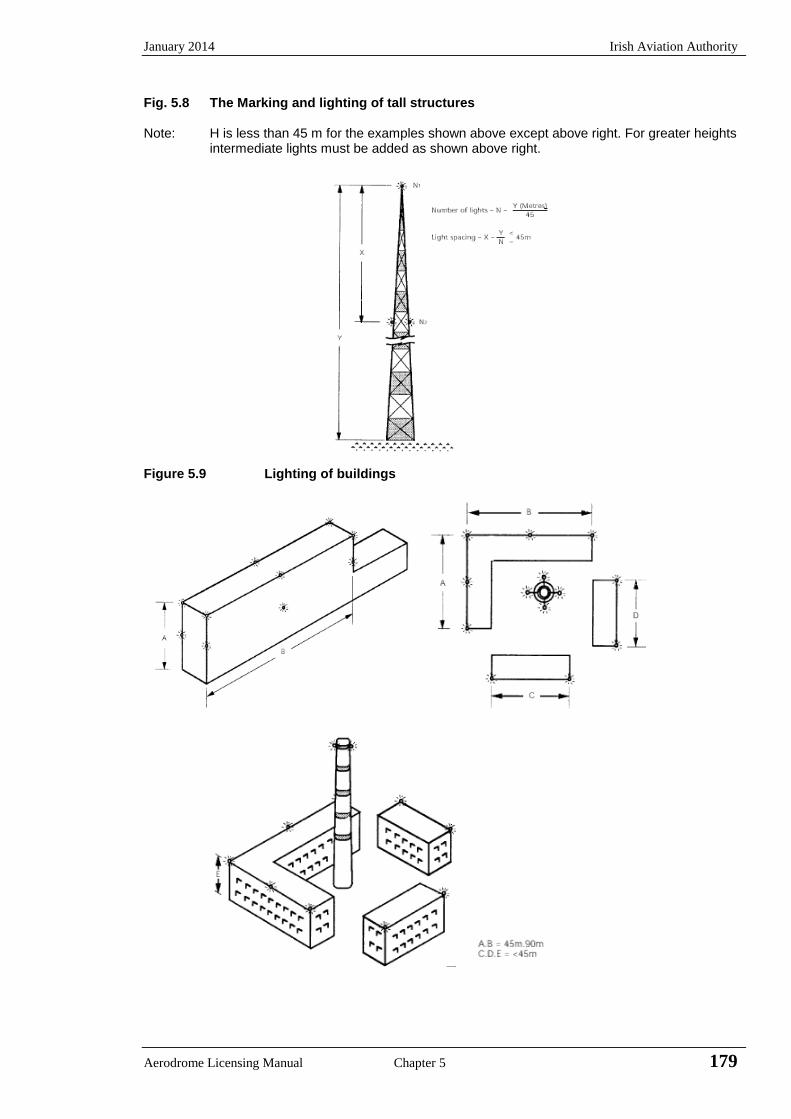
January 2014 Irish Aviation Authority
Aerodrome Licensing Manual Chapter 5 179
Fig. 5.8 The Marking and lighting of tall structures Note: H is less than 45 m for the examples shown above except above right. For greater heights
intermediate lights must be added as shown above right.
Figure 5.9 Lighting of buildings
Irish Aviation Authority January 2014
180 Chapter 5 Aerodrome Licensing Manual
5.4.4.13 In the case of a tower or antenna structure indicated by high-intensity obstacle lights by day with an appurtenance such as a rod or an antenna, greater than 12 m where it is not practicable to locate a high intensity obstacle light on the top of the appurtenance, such a light shall be located at the highest practicable point and, if practicable, a medium-intensity obstacle light, Type A, mounted on the top.
5.4.4.14 In the case of an extensive object or of a group of closely spaced objects top
lights shall be displayed at least on the points or edges of the objects highest in relation to the obstacle limitation surface, so as to indicate the general definition and extent of the objects. If two or more edges are of the same height, the edge nearest the landing area shall be marked. Where low intensity lights are used, they shall be spaced at longitudinal intervals not exceeding 45 m. Where medium intensity lights are used they shall be spaced at longitudinal intervals not exceeding 900 m.
5.4.4.15 When the obstacle limitation surface concerned is sloping and the highest point
above the obstacle limitation surface is not the highest point of the object additional obstacle lights should be placed on the highest point of the object.
5.4.4.16 Where an object is indicated by medium-intensity obstacle lights, Type A, and
the top of the object is no more than 105 m above the level of the surrounding ground or the elevation of the tops of nearby buildings (when the object to be marked is surrounded by buildings) additional lights shall be provided at intermediate levels. These additional intermediate lights shall be spaced as equally as practicable, between the top lights and ground level or the level of the tops of nearby buildings as appropriate with the spacing not exceeding 105 m (see 5.4.4.7).
5.4.4.17 Where an object is indicated by medium-intensity obstacle lights, Type B, and
the top of the object is more than 45 m above the level of the surrounding ground or the elevation of the tops of nearby buildings (when the object to be marked is surrounded by buildings) additional lights shall be provided at intermediate levels. These additional intermediate lights shall be alternately low-intensity obstacle lights, Type B, and medium-intensity obstacle lights, Type B, and shall be spaced as equally as practicable between the top lights and ground level or the level of tops of nearby buildings as appropriate with the spacing not exceeding 52 m.
5.4.4.18 Where an object is indicated by medium-intensity obstacle lights, Type C, and
the top of the object is more than 45 m above the level of the surrounding ground or the elevation of the tops of nearby buildings (when the object to be marked is surrounded by buildings) additional lights shall be provided at intermediate levels. These additional intermediate lights shall be spaced as equally as practicable between the top lights and ground level or the level of tops of nearby buildings as appropriate with the spacing not exceeding 52 m.
5.4.4.19 Where high-intensity obstacle lights, Type A, are used they shall be spaced at
uniform intervals not exceeding 105 m between the ground level and top light(s) specified in 5.4.4.11 except that where an object to be marked is surrounded by buildings, the elevation of the tops of the buildings may be used as the equivalent of the ground level when determining the number of light levels.
5.4.4.20 Where high-intensity obstacle lights Type B are used they shall be located at
three levels:
at the top of the tower,
at the lowest level of the catenary of the wire or cables, and
at approximately midway between these two levels. Note: In some cases this, may require locating the lights off the tower.
January 2014 Irish Aviation Authority
Aerodrome Licensing Manual Chapter 5 181
5.4.4.21 The installation and setting angles for high-intensity obstacle lights, Types A
and B, should be in accordance with Table 5.10.
Table 5.10 Installation setting angles for high-intensity obstacle lights
Height of light unit above terrain Angle of the peak of the beam above the
horizontal
greater than 152 m AGL 0o
122 m to 151 m AGL 1o
92 m to 122 m AGL 2o
less than 92 m AGL 3o
5.4.4.22 The number and arrangement of low, medium or high-intensity obstacle lights at each level to be marked shall be such that the object is indicated from every angle of azimuth. Where a light is shielded in any direction by another part of the object or an adjacent object, additional lights shall be provided on that object in such a way as to retain the general definition of the object to be lighted. If the shielded light does not contribute to the definition of the object to be lighted it may be omitted.
5.4.5 Characteristics of obstacle lights
5.4.5.1 Low-intensity obstacle lights on fixed objects, Types A and B shall be fixed red lights and shall be in accordance with the specifications in Table 5.11.
5.4.5.2 Low-intensity obstacle lights, Types A and B, shall be in accordance with specifications in Table 5.11.
5.4.5.3 Low intensity obstacle lights displayed on vehicles, Type C, associated with
emergency or security shall be flashing blue and those displayed on other vehicles shall be flashing yellow.
5.4.5.4 Low intensity obstacle lights displayed on follow-me vehicles, Type D, shall be
flashing yellow.
5.4.5.5 Low-intensity obstacle lights, Types C and D, shall be in accordance with the specifications in Table 5.11.
5.4.5.6 Low-intensity obstacle lights on objects with limited mobility, such as
aerobridges shall be fixed red. The intensity of the lights shall be sufficient to ensure conspicuity considering the intensity of the adjacent lights and the general levels of illumination against which they would be normally viewed. The intensity of lights shall as a minimum be in accordance with the specifications for low intensity obstacle lights, Type A, in Table 5.11.
5.4.5.7 Low-intensity obstacle lights on objects with limited mobility shall as a minimum be in accordance with the specifications for low-intensity obstacle lights, Type A, in Table 5.11.
5.4.5.8 Medium-intensity obstacle lights, Type A, shall be flashing-white lights, Type B
shall be flashing-red lights and Type C shall be fixed red lights.
5.4.5.9 Medium-intensity obstacle lights, Types A, B, and C shall be in accordance with the specifications in Table 5.11.
5.4.5.10 Medium-intensity obstacle lights, Types A and B, located on an object shall
flash simultaneously. 5.4.5.11 High-intensity obstacle lights, Types A and B, shall be flashing white lights
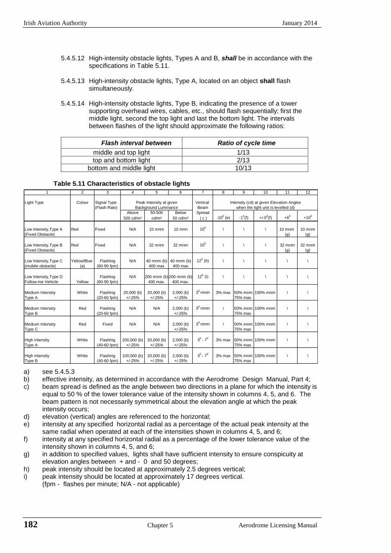
Irish Aviation Authority January 2014
182 Chapter 5 Aerodrome Licensing Manual
5.4.5.12 High-intensity obstacle lights, Types A and B, shall be in accordance with the
specifications in Table 5.11.
5.4.5.13 High-intensity obstacle lights, Type A, located on an object shall flash simultaneously.
5.4.5.14 High-intensity obstacle lights, Type B, indicating the presence of a tower
supporting overhead wires, cables, etc., should flash sequentially; first the middle light, second the top light and last the bottom light. The intervals between flashes of the light should approximate the following ratios:
Flash interval between Ratio of cycle time
middle and top light 1/13
top and bottom light 2/13
bottom and middle light 10/13
Table 5.11 Characteristics of obstacle lights
1 2 3 4 5 6 7 8 9 10 11 12
Light Type Colour Signal Type Peak Intensity at given Vertical Intensity (cd) at given Elevation Angles
(Flash Rate) Background Luminance Beam when the light unit is levelled (d)
Above 50-500 Below Spread
500 cd/m² cd/m² 50 cd/m² ( c ) -100 (e) -1
0(f) +/-0
0(f) +6
0+10
0
Low Intensity,Type A Red Fixed N/A 10 mnm 10 mnn 100
\ \ \ 10 mnm 10 mnm
(Fixed Obstacle) (g) (g)
Low Intensity,Type B Red Fixed N/A 32 mnm 32 mnm 100
\ \ \ 32 mnm 32 mnm
(Fixed Obstacle) (g) (g)
Low Intensity,Type C Yellow/Blue Flashing N/A 40 mnm (b) 40 mnm (b) 120 (h) \ \ \ \ \
(mobile obstacle) (a) (60-90 fpm) 400 max 400 max
Low Intensity,Type D Flashing N/A 200 mnm (b) 200 mnm (b) 120 (i) \ \ \ \ \
Follow-me Vehicle Yellow (60-90 fpm) 400 max. 400 max.
Medium Intensity White Flashing 20,000 (b) 20,000 (b) 2,000 (b) 30
mnm 3% max 50% mnm 100% mnm \ \
Type A (20-60 fpm) +/-25% +/-25% +/-25% 75% max
Medium Intensity Red Flashing N/A N/A 2,000 (b) 30
mnm \ 50% mnm 100% mnm \ \
Type B (20-60 fpm) +/-25% 75% max
Medium Intensity Red Fixed N/A N/A 2,000 (b) 30
mnm \ 50% mnm 100% mnm \ \
Type C +/-25% 75% max
High Intensity White Flashing 200,000 (b) 20,000 (b) 2,000 (b) 30
- 70
3% max 50% mnm 100% mnm \ \
Type A (40-60 fpm) +/-25% +/-25% +/-25% 75% max
High Intensity White Flashing 100,000 (b) 20,000 (b) 2,000 (b) 30
- 70
3% max 50% mnm 100% mnm \ \
Type B (40-60 fpm) +/-25% +/-25% +/-25% 75% max
a) see 5.4.5.3 b) effective intensity, as determined in accordance with the Aerodrome Design Manual, Part 4; c) beam spread is defined as the angle between two directions in a plane for which the intensity is
equal to 50 % of the lower tolerance value of the intensity shown in columns 4, 5, and 6. The beam pattern is not necessarily symmetrical about the elevation angle at which the peak intensity occurs;
d) elevation (vertical) angles are referenced to the horizontal; e) intensity at any specified horizontal radial as a percentage of the actual peak intensity at the
same radial when operated at each of the intensities shown in columns 4, 5, and 6; f) intensity at any specified horizontal radial as a percentage of the lower tolerance value of the
intensity shown in columns 4, 5, and 6; g) in addition to specified values, lights shall have sufficient intensity to ensure conspicuity at
elevation angles between + and - 0 and 50 degrees; h) peak intensity should be located at approximately 2.5 degrees vertical; i) peak intensity should be located at approximately 17 degrees vertical.
(fpm - flashes per minute; N/A - not applicable)
January 2014 Irish Aviation Authority
Aerodrome Licensing Manual Chapter 5 183
5.4.6 Wind turbines
5.4.6.1 A wind turbine shall be marked and/or lighted if it is determined to be an obstacle. 5.4.6.2 The rotor blades, nacelle and upper 2/3 of the supporting mast of wind turbines should be
painted white, unless otherwise indicated by an aeronautical study. 5.4.6.3 When lighting is deemed necessary, medium intensity obstacle lights should be used. In the
case of a wind farm, i.e. a group of two or more wind turbines, it should be regarded as an extensive object and the lights should be installed:
a) to identify the perimeter of the wind farm; b) respecting the maximum spacing, in accordance with 5.4.4.14, between the lights along the
perimeter, unless a dedicated assessment shows that a greater spacing can be used; c) so that, where flashing lights are used, they flash simultaneously; and d) so that, within a wind farm, any wind turbines of significantly higher elevation are also
identified wherever they are located. 5.4.6.4 The obstacle lights should be installed on the nacelle in such a manner as to provide an
unobstructed view for aircraft approaching from any direction.

Irish Aviation Authority January 2014
184 Chapter 5 Aerodrome Licensing Manual
INTENTIONALLY BLANK
January 2014 Irish Aviation Authority
Aerodrome Licensing Manual Chapter 6 185
CHAPTER 6 EMERGENCY SERVICES
6.1 Aerodrome Emergency Planning
6.1.1 Introduction
6.1.1.1 Aerodrome emergency planning is the process of preparing an aerodrome to
cope with an emergency occurring at the aerodrome or in its vicinity. The objective of aerodrome emergency planning is to minimise the effects of an emergency, particularly in respect of saving lives and maintaining aircraft operations. The aerodrome emergency plan sets forth the procedures for co-ordinating the response of different aerodrome agencies or (services) and of those agencies in the surrounding community that could be of assistance in responding to the emergency.
Note: Guidance material to assist in establishing Aerodrome emergency planning is
given in the Airport Services Manual Part 7 (Doc 9137).
6.1.2 The aerodrome emergency plan
6.1.2.1 An aerodrome emergency plan shall be established at an aerodrome, commensurate with the aircraft operations and other activities conducted at the aerodrome.
6.1.2.2 The aerodrome emergency plan shall provide for the co-ordination of the
actions to be taken in an emergency occurring at the aerodrome or in its vicinity.
Notes: 1. Examples of emergencies are: aircraft emergencies, sabotage including bomb threats, unlawfully seized aircraft, dangerous goods occurrences, building fires, natural disaster and public health emergencies.
2. Examples of public health emergencies are increased risk of travellers or
cargo spreading a serious communicable disease internationally through air transport and severe outbreak of a communicable disease potentially affecting a large proportion of aerodrome staff.
6.1.2.3 The plan shall co-ordinate the response or participation of all existing agencies
which, in the opinion of the Authority could be of assistance in responding to an emergency.
Notes: 1 Examples of agencies are: - on the aerodrome: air traffic control units, rescue and fire fighting services,
aerodrome administration, medical and ambulance services, aircraft operators, security services and police;
- off the aerodrome: fire departments, garda, health authorities (including medical, ambulance, hospital and public health services), military, and harbour patrol or coastguard.
2 Public health services include planning to minimise adverse effects to the
community from health related events and deal with population health issues rather than provision of health services to individuals.
6.1.2.4 The plan should provide for co-operation and co-ordination with the rescue co-
ordination centre, as necessary.
Irish Aviation Authority January 2014
186 Chapter 6 Aerodrome Licensing Manual
6.1.2.5 The aerodrome emergency plan document should include at least the following:
a) types of emergencies planned for; b) agencies involved in the plan; c) responsibility and role of each agency, the emergency operations centre
and the command post, for each type of emergency; d) information on names and telephone numbers of offices or people to be
contacted in the case of a particular emergency (Note: this list to be maintained up to date) and
e) a grid map of the aerodrome and its immediate vicinity.
6.1.2.6 The plan shall observe Human Factors principles to ensure optimum response by all existing agencies participating in emergency operations.
Note Guidance material on Human Factors principles can be found in Human
Factors Training Manual, Doc. 9683.
6.1.2.7 A fixed emergency operations centre and a mobile command post should be available for use during an emergency.
6.1.2.8 The emergency operations centre should be part of the aerodrome facilities and
should be responsible for the over-all co-ordination and general direction of the response to an emergency.
6.1.2.9 The command post should be a facility capable of being moved rapidly to the
site of an emergency, when required, and should undertake the local co-ordination of those agencies responding to the emergency.
6.1.2.10 A person should be assigned to assume control of the emergency operations
centre and, when appropriate, another person for the command post.
6.1.2.11 Adequate communication systems linking the command post and the emergency operations centre with each other and with the participating services should be provided in accordance with the plan and consistent with the particular requirements of the aerodrome.
6.1.3 Aerodrome emergency exercise
6.1.3.1 The plan shall contain procedures for periodic testing of the adequacy of the plan and for reviewing the results in order to improve its effectiveness.
Note The plan includes all participating agencies and associated equipment.
6.1.3.2 The plan shall be tested by conducting:
a) a full-scale emergency exercise at intervals not exceeding two years; and
partial emergency exercises in the intervening year to ensure that the deficiencies found during the full-scale aerodrome emergency exercise have been corrected; and
b) a series of modular tests commencing in the first year and concluding in a full-scale aerodrome emergency exercise at intervals not exceeding three years;
and reviewed thereafter, or after an actual emergency, so as to correct any deficiency found during such exercises or actual emergency.
Notes 1 The purpose of a full-scale exercise is to ensure the adequacy of the plan to
cope with different types of emergencies. The purpose of a partial exercise is to ensure the adequacy of the response to individual participating services and components of the plan, such as, the communications system. The purpose of

January 2014 Irish Aviation Authority
Aerodrome Licensing Manual Chapter 6 187
modular tests is to enable concentrated effort on specific components of established emergency plans.
2 The Authority shall be informed at least one month in advance of an
emergency exercise. 3 The emergency plan may be considered adequately tested if a major aircraft
incident occurs at the Airport.
6.2 Emergencies in Difficult Environments
6.2.1.1 The plan shall include the ready availability of and coordination with appropriate specialist rescue services to be able to respond to emergencies where an aerodrome is located close to water and/or swampy areas and where a significant portion of approach or departure operations takes place over these areas.
6.2.1.2 At those aerodromes located close to water and/or swampy areas, or difficult
terrain, the aerodrome emergency plan should include the establishment, testing and assessment at regular intervals of a pre-determined response for the specialist rescue services.
6.2.1.3 An assessment of the approach and departure areas within 1 000 m of the runway threshold should be carried out to determine the options available for intervention.
Note Guidance material on assessing approach and departure areas within 1 000 m of runway thresholds can be found in Chapter 13 of the Airport Services Manual (Doc 9137), Part 1.
6.3 Rescue and Fire Fighting
6.3.1 General
6.3.1.1 The principle objective of a rescue and fire fighting service is to save lives in the event of an aircraft accident or incident occurring at, or in the vicinity of, an aerodrome. The rescue and fire-fighting service is provided to create and maintain survivable conditions, to provide egress routes for occupants and to initiate the rescue of those occupants unable to make their escape without direct aid. The rescue may require the use of equipment and personnel other than those assessed primarily for rescue and fire-fighting purposes.
The most important factors bearing on effective rescue in a survivable aircraft accident are: the training received, the effectiveness of the equipment and the speed with which personnel and equipment designated for rescue and fire fighting purposes can be put into use.
Requirements to combat building and fuel farm fires or to deal with foaming of runways are not taken into account.
6.3.2 Application
6.3.2.1 Rescue and fire fighting equipment and services shall be provided at an aerodrome.
Note: Public or private organisations suitably located and, equipped and trained in
aviation fire fighting, may be designated to provide the rescue and fire fighting service. It is intended that the fire station housing these organisations be normally located on the aerodrome, although an off-aerodrome location is not precluded provided the response times can be met.
Irish Aviation Authority January 2014
188 Chapter 6 Aerodrome Licensing Manual
6.3.2.2 Where an aerodrome is located close to water/swampy areas, or difficult
terrain, and where a significant portion of approach or departure operations takes place over these areas, specialist rescue services and fire fighting equipment appropriate to the hazard and risk shall be available.
Notes: 1 Special fire fighting equipment need not be provided for water areas; this does
not prevent the provision of such equipment if it would be of practical use, such as when the areas concerned include reefs and islands.
2 The objective is to plan and deploy the necessary life-saving flotation
equipment as expeditiously as possible in a number commensurate with the largest aeroplane normally using the aerodrome.
3 Additional guidance is gives in Appendix 6A, Section 6A.2 and in Chapter 13
of Airport Services Manual, Part 1 (Doc 9137).
6.3.3 Level of protection to be provided
6.3.3.1 The level of protection to be provided at an aerodrome for rescue and fire
fighting shall be appropriate to the aerodrome category determined using the principles in 6.2.3.2 and 6.2.3.3, except that, where the number of movements of the aeroplanes in the highest category normally using the aerodrome is less than 700 in the busiest consecutive three months, the level of protection provided shall be not less than one category below the determined category.
Note Either a take-off or a landing constitutes a movement.
6.3.3.2 The level of protection to be provided at an aerodrome for rescue and fire fighting should be equal to the aerodrome category determined using the principles in 6.2.3.2 and 6.2.3.3.
6.3.3.3 The aerodrome category shall be determined from Table 6.1 and shall be
based on the longest aeroplanes normally using the aerodrome and their fuselage width.
Note To categorise the aeroplanes using the aerodrome first evaluate the over-all
length and second their fuselage width.
6.3.3.4 If, after selecting the category appropriate to the longest aeroplane’s over-all length that aeroplane’s fuselage width is greater than the maximum width in Table 6.1 column 3 for that category, then the aerodrome category for that aeroplane shall actually be one category higher.
Note 1 See guidance in the Airport Services Manual, Part 1 (Doc 9137) for
categorising aerodromes, including those for all-cargo aircraft operations, for rescue and fire-fighting purposes.
2 Guidance on training of personnel, rescue equipment for difficult environments and other facilities and services for rescue and fire fighting is given in Annex 14, Attachment A, Section 18, and in the Airport Services Manual (Doc 9137), Part 1.
6.3.3.5 During anticipated periods of reduced activity, the level of protection available
shall not be less than that needed for the highest category of aeroplane planned to use the aerodrome during that time irrespective of the number of movements.
6.3.3.6 The aerodrome rescue and firefighting service shall be available at least 15 minutes prior to the expected arrival of the first aircraft and after the last aircraft has departed the aerodrome
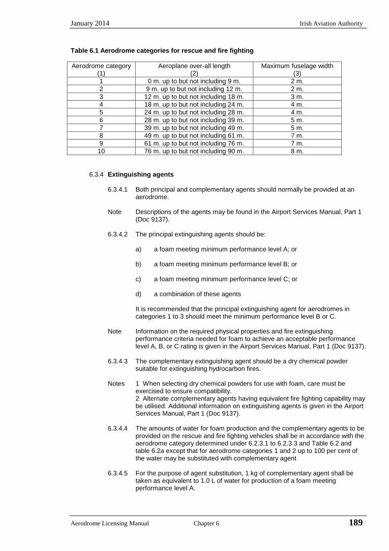
January 2014 Irish Aviation Authority
Aerodrome Licensing Manual Chapter 6 189
Table 6.1 Aerodrome categories for rescue and fire fighting
Aerodrome category Aeroplane over-all length Maximum fuselage width (1) (2) (3) 1 0 m. up to but not including 9 m. 2 m. 2 9 m. up to but not including 12 m. 2 m. 3 12 m. up to but not including 18 m. 3 m. 4 18 m. up to but not including 24 m. 4 m. 5 24 m. up to but not including 28 m. 4 m. 6 28 m. up to but not including 39 m. 5 m. 7 39 m. up to but not including 49 m. 5 m. 8 49 m. up to but not including 61 m. 7 m. 9 61 m. up to but not including 76 m. 7 m. 10 76 m. up to but not including 90 m. 8 m.
6.3.4 Extinguishing agents
6.3.4.1 Both principal and complementary agents should normally be provided at an aerodrome.
Note Descriptions of the agents may be found in the Airport Services Manual, Part 1
(Doc 9137).
6.3.4.2 The principal extinguishing agents should be:
a) a foam meeting minimum performance level A; or
b) a foam meeting minimum performance level B; or
c) a foam meeting minimum performance level C; or
d) a combination of these agents
It is recommended that the principal extinguishing agent for aerodromes in categories 1 to 3 should meet the minimum performance level B or C.
Note Information on the required physical properties and fire extinguishing
performance criteria needed for foam to achieve an acceptable performance level A, B, or C rating is given in the Airport Services Manual, Part 1 (Doc 9137).
6.3.4.3 The complementary extinguishing agent should be a dry chemical powder
suitable for extinguishing hydrocarbon fires.
Notes 1 When selecting dry chemical powders for use with foam, care must be exercised to ensure compatibility.
2 Alternate complementary agents having equivalent fire fighting capability may be utilised. Additional information on extinguishing agents is given in the Airport Services Manual, Part 1 (Doc 9137).
6.3.4.4 The amounts of water for foam production and the complementary agents to be provided on the rescue and fire fighting vehicles shall be in accordance with the aerodrome category determined under 6.2.3.1 to 6.2.3.3 and Table 6.2 and table 6.2a except that for aerodrome categories 1 and 2 up to 100 per cent of the water may be substituted with complementary agent
6.3.4.5 For the purpose of agent substitution, 1 kg of complementary agent shall be taken as equivalent to 1.0 L of water for production of a foam meeting performance level A.

Irish Aviation Authority January 2014
190 Chapter 6 Aerodrome Licensing Manual
Notes 1 The amounts of water specified for foam production are predicated on an
application rate of 8.2 l/min/m2 for a foam meeting performance level A and 5.5
l/min/m2 for a foam meeting performance level B, and 3.75 L/min/m2 for a foam
meeting performance level C 2. When any other complementary agent is used, then the substitution ratios will
need to be checked.
6.3.4.6 At aerodromes where operations by aeroplanes larger than the average size in a given category are planned, the quantities of water shall be recalculated and the amount of water for foam production and the discharge rates for foam solution should be increased accordingly.
Note Guidance on the determination of quantities of water and discharge rates based
on the largest theoretical aeroplane in a given category is available in Chapter 2 of the Airport Services Manual (Doc 9137), Part 1.
6.3.4.7 The quantity of foam concentrates separately provided on vehicles for foam
production shall be in proportion to the quantity of water provided and the foam concentrate selected.
6.3.4.8 The amount of foam concentrates provided on a vehicle should be sufficient to
produce at least two loads of foam solution.
6.3.4.9 Supplementary water supplies, for the expeditious replenishment of rescue vehicles at the scene of an aircraft accident, should be provided.
6.3.4.10 When a combination of different performance level foams are provided at an
aerodrome, the total amount of water to be provided for foam production should be calculated for each foam type and the distribution of these quantities should be documented for each vehicle and applied to the overall rescue and fire fighting requirement.
Table 6.2 Minimum usable amounts of extinguishing agents
Aerodrome category
(1)
Foam meeting performance level A
Foam meeting performance level B
Foam meeting performance level C
Water1
(L) (2)
Discharge rate foam solution L/minute (3)
Water1
(L) (4)
Discharge rate foam solution L/minute (5)
Water1
(L) (6)
Discharge rate foam solution L/minute (7)
1 230 230 160 160
2 670 550 460 360
3 1 200 900 820 630
4 3 600 2 600 2 400 1 800 1700 1100
5 8 100 4 500 5 400 3 000 3900 2200
6 11 800 6 000 7 900 4 000 5800 2900
7 18 200 7 900 12 100 5 300 8800 3800
8 27 300 10 800 18 200 7 200 12800 5100
9 36 400 13 500 24 300 9 000 17100 6300
10 48 200 16 600 32 300 11 200 22800 7900
Note: 1 The quantities of water shown in columns 2, 4 and 6 are based on the
average over-all length of aeroplanes in a given category.
6.3.4.11 The discharge rate of the foam solution shall not be less than the rates shown in Table 6.2.
6.3.4.12 The complementary agent shall comply with the appropriate specifications of the International Organisation for standardisation (ISO).
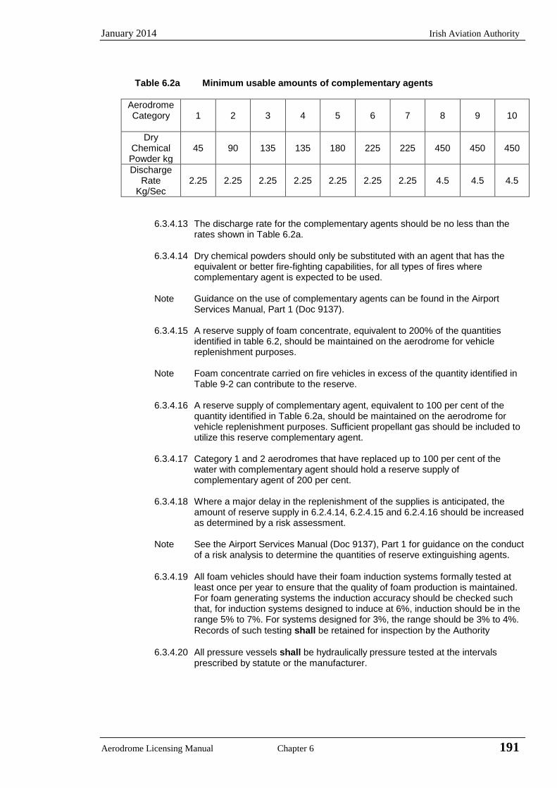
January 2014 Irish Aviation Authority
Aerodrome Licensing Manual Chapter 6 191
Table 6.2a Minimum usable amounts of complementary agents
Aerodrome Category
1
2
3
4
5
6
7
8
9
10
Dry Chemical Powder kg
45
90
135
135
180
225
225
450
450
450
Discharge Rate
Kg/Sec
2.25
2.25
2.25
2.25
2.25
2.25
2.25
4.5
4.5
4.5
6.3.4.13 The discharge rate for the complementary agents should be no less than the rates shown in Table 6.2a.
6.3.4.14 Dry chemical powders should only be substituted with an agent that has the
equivalent or better fire-fighting capabilities, for all types of fires where complementary agent is expected to be used.
Note Guidance on the use of complementary agents can be found in the Airport
Services Manual, Part 1 (Doc 9137).
6.3.4.15 A reserve supply of foam concentrate, equivalent to 200% of the quantities identified in table 6.2, should be maintained on the aerodrome for vehicle replenishment purposes.
Note Foam concentrate carried on fire vehicles in excess of the quantity identified in Table 9-2 can contribute to the reserve.
6.3.4.16 A reserve supply of complementary agent, equivalent to 100 per cent of the quantity identified in Table 6.2a, should be maintained on the aerodrome for vehicle replenishment purposes. Sufficient propellant gas should be included to utilize this reserve complementary agent.
6.3.4.17 Category 1 and 2 aerodromes that have replaced up to 100 per cent of the water with complementary agent should hold a reserve supply of complementary agent of 200 per cent.
6.3.4.18 Where a major delay in the replenishment of the supplies is anticipated, the
amount of reserve supply in 6.2.4.14, 6.2.4.15 and 6.2.4.16 should be increased as determined by a risk assessment.
Note See the Airport Services Manual (Doc 9137), Part 1 for guidance on the conduct
of a risk analysis to determine the quantities of reserve extinguishing agents.
6.3.4.19 All foam vehicles should have their foam induction systems formally tested at
least once per year to ensure that the quality of foam production is maintained. For foam generating systems the induction accuracy should be checked such that, for induction systems designed to induce at 6%, induction should be in the range 5% to 7%. For systems designed for 3%, the range should be 3% to 4%.
Records of such testing shall be retained for inspection by the Authority
6.3.4.20 All pressure vessels shall be hydraulically pressure tested at the intervals prescribed by statute or the manufacturer.
Irish Aviation Authority January 2014
192 Chapter 6 Aerodrome Licensing Manual
6.3.5 Rescue equipment
6.3.5.1 Rescue equipment commensurate with the level of aircraft operations should be
provided on the rescue and fire fighting vehicle(s).
Note Guidance on the rescue equipment to be provided at an aerodrome is given in Appendix 6D. See also the Airport Services Manual, Part 1 (Doc 9137).
6.3.6 Response time
6.3.6.1 The operational objective of the rescue and fire fighting service shall be to achieve response time not exceeding three minutes to any point of each operational runway in optimum visibility and surface conditions.
6.3.6.2 The operational objective of the rescue and fire fighting service should be to
achieve response time not exceeding two minutes to any point of each operational runway in optimum visibility and surface conditions.
6.3.6.3 The operational objective of the rescue and fire fighting service should be to
achieve a response time not exceeding three minutes to any other point of the movement area in optimum visibility and surface conditions
Notes: 1. Response time is considered to be the time between the initial call to the
rescue and fire fighting service, and the time when the first responding vehicle(s) is (are) in position to apply foam at a rate of at least 50 % of the discharge rate specified in Table 6.2.
2. Optimum visibility and surface conditions are defined as daytime, good visibility, no precipitation with normal response route free of surface contamination e.g. water, ice, snow.
6.3.6.4 To meet the operational objective as nearly as possible in less than optimum
conditions of visibility, especially during low visibility operations, suitable guidance, equipment and/or procedures for rescue and fire-fighting services should be provided.
Note: Additional guidance is given in Airport Services Manual Part 1 (Doc 9137).
6.3.6.5 Any vehicles, other than the first responding vehicle(s), required to deliver the
amounts of extinguishing agent specified in Table 6.2 shall ensure continuous
agent application and shall arrive no more than four minutes from the initial call.
6.3.6.6 Any vehicles, other than the first responding vehicle(s), required to deliver the amounts of extinguishing agents specified in Table 6.2 should ensure continuous agent application and should arrive no more than three minutes from the initial call.
6.3.6.7 A system of preventive maintenance of rescue and fire fighting vehicles should
be employed to ensure effectiveness of the equipment and compliance with the specified response time throughout the life of the vehicle. Records of such
maintenance shall be maintained for inspection by the Authority.
6.3.7 Emergency access roads
6.3.7.1 Emergency access roads should be provided on an aerodrome where terrain conditions permit their construction, so as to facilitate achieving minimum response times. Particular attention should be given to the provision of ready access to approach areas up to 1000 m from the threshold, or at least within the aerodrome boundary. Where a fence is provided, the need for convenient access to outside areas should be taken into account.
January 2014 Irish Aviation Authority
Aerodrome Licensing Manual Chapter 6 193
Note: Aerodrome service roads may serve as emergency access roads when they are suitably located and constructed.
6.3.7.2 Emergency access roads should be capable of supporting the heaviest vehicles
which will use them, and be usable in all weather conditions. Roads within 90 m of a runway should be surfaced to prevent surface erosion and the transfer of debris to the runway. Sufficient vertical clearance should be provided from overhead obstructions for the largest vehicles.
6.3.7.3 When the surface of the road is indistinguishable from the surrounding area, or
in areas where snow may obscure the location of the roads, suitable edge markers should be placed at intervals of about 10 m.
6.3.8 Fire stations
6.3.8.1 All rescue and fire fighting vehicles should normally be housed in a fire station.
Satellite fire stations should be provided whenever the response time cannot be achieved from a single fire station.
6.3.8.2 The fire station should be located so that the access for rescue and fire fighting
vehicles into the runway area is direct and clear, requiring a minimum number of turns.
6.3.9 Communications and alerting systems
6.3.9.1 A discrete communication system should be provided linking the fire station with the control tower, any other fire station on the aerodrome and rescue and fire fighting vehicles.
Note: See Appendix 6A, section 6A.3 for additional guidance.
6.3.9.2 An alerting system for rescue and fire fighting personnel, capable of being
operated from that station, should be provided at a fire station, any other fire station on the aerodrome and the aerodrome control tower.
6.3.10 Number of rescue and fire fighting vehicles
6.3.10.1 The minimum number of rescue and fire fighting vehicles provided at an aerodrome should be in accordance with the following tabulation:
Aerodrome category Rescue and fire fighting vehicles
1 1
2 1
3 1
4 1
5 1
6 2
7 2
8 3
9 3
10 3
Note: Guidance on minimum specifications and characteristics of rescue and fire fighting vehicles is given in the Airport Services Manual, Part 1 (Doc 9137).
Irish Aviation Authority January 2014
194 Chapter 6 Aerodrome Licensing Manual
6.3.11 Personnel
6.3.11.1 All rescue and fire fighting personnel shall be properly trained to perform their duties in an efficient manner and shall participate in live fire drills commensurate with the types of aircraft and type of rescue and fire fighting equipment in use on the aerodrome, including pressure-fed fuel fires.
Notes: 1 Guidance to assist in providing proper training is given in Annex 14,
Attachment A, Section 17 and Airport Services Manual, Part 1 (Doc 9137). 2 Fires associated with fuel discharged under very high pressure from a
ruptured fuel tank are known as ‘pressure-fed fuel fires’.
6.3.11.2 The rescue and fire fighting personnel training programme shall include training in human performance, including team coordination.
Note: Guidance material to design training programmes on human performance and
team co-ordination can be found in the Human Factors Training Manual, Doc 9683.
6.3.11.3 During flight operations, sufficient trained personnel should be detailed and be
readily available to ride the rescue and fire fighting vehicles and to operate the equipment at maximum capacity. These trained personnel should be deployed in a way that ensures minimum response times can be achieved and that continuous agent application at the appropriate rate can be fully maintained. Consideration should also be given for personnel to use hand lines, ladders and other rescue and fire fighting equipment normally associated with aircraft rescue and fire fighting operations.
6.3.11.4 In determining the minimum number of rescue and fire fighting personnel
required, a task resource analysis should be completed and the level of staffing documented in the Aerodrome Manual.
Note Guidance on the use of a task resource analysis can be found in the Airport
Services Manual (Doc 9137), Part 1.
6.3.11.5 All responding rescue and fire fighting personnel shall be provided with protective clothing and respiratory equipment to enable them to perform their duties safely and in an effective manner.
6.3.11.6 There shall be an appropriately qualified Officer in Charge of the rescue and fire
fighting crew at all times the aerodrome is open for aircraft operations.
January 2014 Irish Aviation Authority
Aerodrome Licensing Manual Chapter 6 195
APPENDIX 6A Rescue and Fire Fighting: Supplementary Information
6A.1 Administration
6A.1.1 In drawing up the detailed plan for the conduct of search and rescue operations in
accordance with paragraph 4.2.1 of Annex 12, Search and Rescue, the aerodrome authority should co-ordinate its plans with the rescue co-ordination centre to ensure that the respective limits of their responsibilities for an aircraft accident within the vicinity of an aerodrome are clearly delineated.
6A.1.2 Co-ordination between the rescue and fire fighting service at an aerodrome and public
protective services, such as local fire brigade, police force, hospitals, etc. should be achieved by prior agreement for assistance in dealing with an aircraft accident.
6A.1.3 A grid map of the aerodrome and its immediate vicinity should be provided for the use
of the aerodrome services concerned. Information concerning topography, access roads and location of water supplies should be indicated. This map should be conspicuously posted in the control tower and fire station and available on the rescue and fire fighting vehicles and such other supporting vehicles required to respond to an aircraft accident or incident. Copies should also be distributed to public agencies as desirable.
6A.1.4 Co-ordinated instructions should be drawn up detailing the responsibilities of all
concerned and the action to be taken in dealing with emergencies.
6A.2 Rescue Equipment for Difficult Environments
6A.2.1 Suitable rescue equipment and services should be available at an aerodrome where the area to be covered includes water, swampy areas or other difficult environment that cannot be fully served by conventional wheeled vehicles. This is particularly important where a significant portion of approach/departure operations takes place over these areas.
6A.2.2 The rescue equipment should be carried on boats, helicopters and amphibious or
other vehicles, capable of operating in the area concerned. The vehicles should be so located that they can be brought into action quickly to respond to the areas covered by the service.
6A.2.3 If these vehicles are located off the aerodrome, they should preferably be under the
control of the aerodrome rescue and fire fighting service or, if this is not practicable, under the control of another competent public or private organisation (such as police, military, harbour authorities, life boats, etc.) working in close co-ordination with the aerodrome rescue and fire fighting service.
6A.2.4 Boats or other vehicles should have as high a speed as practicable so as to reach an
accident site in minimum time. To reduce the possibility of injury during rescue operations, water jet-driven boats are preferred to water propeller driven boats unless the propellers of the latter boats are ducted. Vehicles used in this service should be equipped with life rafts and life preservers related to the requirements of the largest aircraft normally using the aerodrome, with two-way radio communication and floodlights for night operations. If aircraft operations during periods of low visibility are expected it may be necessary to provide additional guidance to the responding emergency vehicles.
6A.2.5 The personnel designated to operate the equipment should be adequately trained and
regularly drilled for rescue services in the appropriate environment.
Irish Aviation Authority January 2014
196 Chapter 6 Aerodrome Licensing Manual
6A.3 Communications and Alerting Systems
6A.3.1 The provision of a special telephone, two-way radio communication and general
alarms for the rescue and fire fighting service is desirable to ensure the dependable transmission of essential emergency and routine information. Consistent with the individual requirements for each aerodrome these facilities serve the following purposes:
a) direct communication between the activating authority and the aerodrome fire
station in order to ensure the prompt alerting and dispatch of rescue and fire fighting vehicles and personnel in the event of an aircraft accident or incident;
b) direct communication between the rescue and fire-fighting service and the flight crew of an aircraft in emergency;
c) emergency signals to ensure the immediate summoning of designated personnel not on standby duty;
d) as necessary, summoning essential related services on or off the aerodrome; and
e) maintaining communication by means of two-way radio with the rescue and fire-fighting vehicles in attendance at an aircraft accident or incident.
6A.3.2 At airports catering for more than 1 million passengers per annum, the frequency of
121.6 MHz shall be made available for direct communication between an aircraft in distress and the Fire and Rescue services.
6A.4 Aerodrome Medical Services
6A.4.1 All licensed aerodromes should be equipped with a nucleus of medical equipment on
a scale appropriate to their category. First aid training should be undertaken by all aerodrome personnel likely to play an active role in rescuing or assisting persons involved in an aircraft accident. This is to ensure that in the early stages following an accident, qualified assistance will be available. Under normal arrangements the ‘Emergency Plan’ will be activated and the initial effort will be supplemented by professional ambulance, medical and nursing assistance within a short time.
6A.4.2 The aerodrome authority should arrange to have sufficient medical supplies available
on or in the vicinity of the airport and carried to the scene of the accident as quickly as possible. The type and quantity of such supplies, to treat the passenger and crew capacity of the largest aircraft normally using the aerodrome, should be determined by the aerodrome authority using the information available in the Airport Services Manual, Part 7. At remote aerodromes where off aerodrome medical support may not be immediately available additional medical supplies may be required.
6A.4.3 A list of medical supplies retained on or in the vicinity of the aerodrome should be
made available to the Authority.
6A.4.4 The availability of ambulance and medical facilities for the removal and after-care of casualties arising from an aircraft accident should receive careful consideration and form part of the overall emergency plan.
6A.4.5 Buildings should be identified:
a) for casualty reception; b) as temporary mortuary accommodation; c) for safeguarding recovered personnel effects; d) as a reception area for grieved and shocked relatives.
6A.4.6 Working in accident conditions without adequate lighting can be extremely difficult and
supplementary lighting should be provided as required.
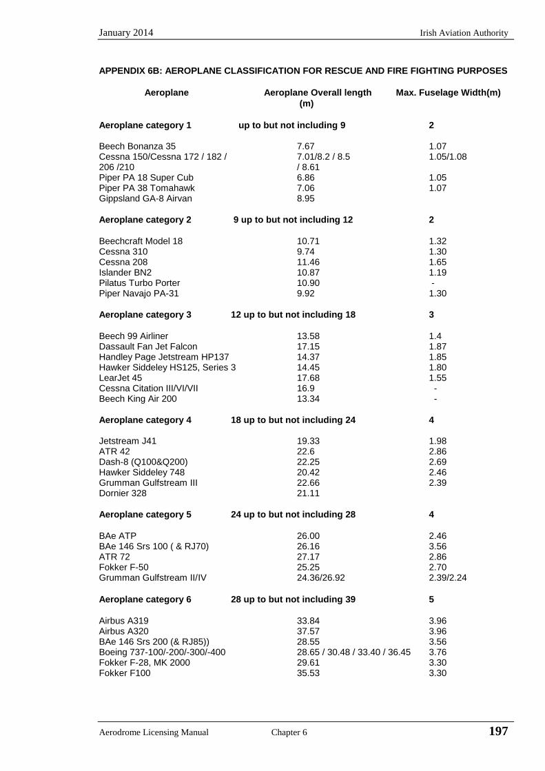
January 2014 Irish Aviation Authority
Aerodrome Licensing Manual Chapter 6 197
APPENDIX 6B: AEROPLANE CLASSIFICATION FOR RESCUE AND FIRE FIGHTING PURPOSES
Aeroplane Aeroplane Overall length Max. Fuselage Width(m)
(m)
Aeroplane category 1 up to but not including 9 2 Beech Bonanza 35 7.67 1.07 Cessna 150/Cessna 172 / 182 / 7.01/8.2 / 8.5 1.05/1.08 206 /210 / 8.61 Piper PA 18 Super Cub 6.86 1.05 Piper PA 38 Tomahawk 7.06 1.07 Gippsland GA-8 Airvan 8.95
Aeroplane category 2 9 up to but not including 12 2
Beechcraft Model 18 10.71 1.32 Cessna 310 9.74 1.30 Cessna 208 11.46 1.65 Islander BN2 10.87 1.19 Pilatus Turbo Porter 10.90 - Piper Navajo PA-31 9.92 1.30
Aeroplane category 3 12 up to but not including 18 3
Beech 99 Airliner 13.58 1.4 Dassault Fan Jet Falcon 17.15 1.87 Handley Page Jetstream HP137 14.37 1.85 Hawker Siddeley HS125, Series 3 14.45 1.80 LearJet 45 17.68 1.55 Cessna Citation III/VI/VII 16.9 - Beech King Air 200 13.34 -
Aeroplane category 4 18 up to but not including 24 4 Jetstream J41 19.33 1.98 ATR 42 22.6 2.86 Dash-8 (Q100&Q200) 22.25 2.69 Hawker Siddeley 748 20.42 2.46 Grumman Gulfstream III 22.66 2.39 Dornier 328 21.11
Aeroplane category 5 24 up to but not including 28 4
BAe ATP 26.00 2.46 BAe 146 Srs 100 ( & RJ70) 26.16 3.56 ATR 72 27.17 2.86 Fokker F-50 25.25 2.70 Grumman Gulfstream II/ IV 24.36/26.92 2.39/2.24
Aeroplane category 6 28 up to but not including 39 5
Airbus A319 33.84 3.96 Airbus A320 37.57 3.96 BAe 146 Srs 200 (& RJ85)) 28.55 3.56 Boeing 737-100/-200/-300/-400 28.65 / 30.48 / 33.40 / 36.45 3.76 Fokker F-28, MK 2000 29.61 3.30 Fokker F100 35.53 3.30
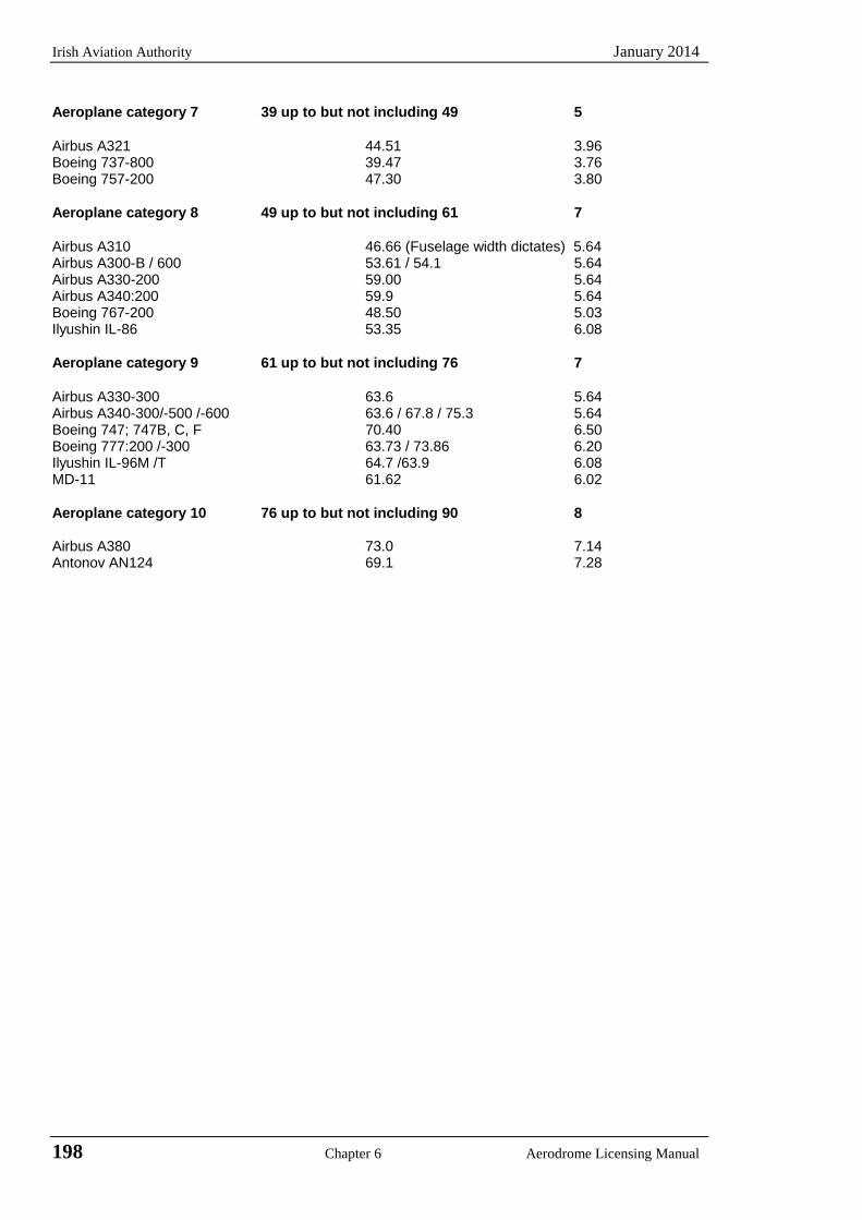
Irish Aviation Authority January 2014
198 Chapter 6 Aerodrome Licensing Manual
Aeroplane category 7 39 up to but not including 49 5
Airbus A321 44.51 3.96 Boeing 737-800 39.47 3.76 Boeing 757-200 47.30 3.80
Aeroplane category 8 49 up to but not including 61 7
Airbus A310 46.66 (Fuselage width dictates) 5.64 Airbus A300-B / 600 53.61 / 54.1 5.64 Airbus A330-200 59.00 5.64 Airbus A340:200 59.9 5.64 Boeing 767-200 48.50 5.03 Ilyushin IL-86 53.35 6.08
Aeroplane category 9 61 up to but not including 76 7
Airbus A330-300 63.6 5.64 Airbus A340-300/-500 /-600 63.6 / 67.8 / 75.3 5.64 Boeing 747; 747B, C, F 70.40 6.50 Boeing 777:200 /-300 63.73 / 73.86 6.20 Ilyushin IL-96M /T 64.7 /63.9 6.08 MD-11 61.62 6.02
Aeroplane category 10 76 up to but not including 90 8 Airbus A380 73.0 7.14 Antonov AN124 69.1 7.28
January 2014 Irish Aviation Authority
Aerodrome Licensing Manual Chapter 6 199
APPENDIX 6C THE PROVISION OF ADDITIONAL WATER FOR USE IN FIRE FIGHTING
OPERATIONS FOLLOWING AN AIRCRAFT ACCIDENT
6C.1 It is considered impractical to require aerodrome authorities to provide quantities of
extinguishing media to deal with the worst situation that may arise using only the appliances located on the aerodrome, hence the requirement for aerodrome emergency plans to include instructions for summoning support from externally based fire services following an emergency. It is not possible to specify an operational requirement that makes adequate provision for all circumstances. With a response time to an accident not exceeding three minutes and the ability to discharge appliances in about two minutes it is clear that a need for additional water may arise in as little as five minutes although in this time the initial fire situation should be greatly reduced. If total extinction has not been achieved the fire can quickly extend and the appliances must be quickly replenished.
6C.2 Aerodromes should consider providing additional water as a support facility. There may be
exceptions where aerodromes have adequate piped, stored or natural water supplies, provided that these are available at an accident site in sufficient quantity and in time to meet the operational requirement.
6C.3 At aerodromes, categories 6 - 10, the aim should be to provide at the earliest possible time a
potential flow of 4540 litres/minute for a minimum period of 30 minutes at the scene of any aircraft accident occurring on the aerodrome.
6C.4 In each case the aerodrome authority should consult closely with the Chief Fire Officer of the
Local Authority Fire Service regarding response and supply of additional water. The aerodrome authority will need to assess the availability of the water resources that can be mobilised to support the aerodrome fire service when a serious and prolonged post accident fire occurs. In this consideration the speed of mobilisation and the rate at which the water can be delivered to the accident site are important factors.
6C.5 The options for providing additional water may include the following:
a) Additional vehicle-borne water on the aerodrome. b) A system that provides for the rapid replenishment of the appliances used in the initial
attack. c) The development of a plan with the externally based fire service which will provide
support by appliances carrying water and /or equipped to deliver water from suitable aerodrome or local sources.
d) The provision of hydrants, static water tanks or overhead static water tanks suitably positioned.
6C.6 The value of supporting facilities to deliver water at an accident site should be tested by
operational exercises.

Irish Aviation Authority January 2014
200 Chapter 6 Aerodrome Licensing Manual
INTENTIONALLY BLANK
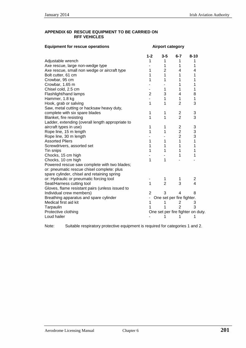
January 2014 Irish Aviation Authority
Aerodrome Licensing Manual Chapter 6 201
APPENDIX 6D RESCUE EQUIPMENT TO BE CARRIED ON
RFF VEHICLES
Equipment for rescue operations Airport category
1-2 3-5 6-7 8-10 Adjustable wrench 1 1 1 1 Axe rescue, large non-wedge type - 1 1 1 Axe rescue, small non wedge or aircraft type 1 2 4 4 Bolt cutter, 61 cm 1 1 1 1 Crowbar, 95 cm 1 1 1 1 Crowbar, 1.65 m - - 1 1 Chisel cold, 2.5 cm - 1 1 1 Flashlight/hand lamps 2 3 4 8 Hammer, 1.8 kg - 1 1 1 Hook, grab or salving 1 1 2 3 Saw, metal cutting or hacksaw heavy duty, complete with six spare blades 1 1 2 3 Blanket, fire resisting 1 1 2 3 Ladder, extending (overall length appropriate to aircraft types in use) 1 1 2 3 Rope line, 15 m length 1 1 2 3 Rope line, 30 m length - - 2 3 Assorted Pliers 1 1 1 1 Screwdrivers, assorted set 1 1 1 1 Tin snips 1 1 1 1 Chocks, 15 cm high - - 1 1 Chocks, 10 cm high 1 1 - - Powered rescue saw complete with two blades; or: pneumatic rescue chisel complete: plus spare cylinder, chisel and retaining spring or: Hydraulic or pneumatic forcing tool - 1 1 2 Seat/Harness cutting tool 1 2 3 4 Gloves, flame resistant pairs (unless issued to Individual crew members) 2 3 4 8 Breathing apparatus and spare cylinder - One set per fire fighter. Medical first aid kit 1 1 2 3 Tarpaulin 1 1 2 3 Protective clothing One set per fire fighter on duty. Loud hailer - 1 1 1 Note: Suitable respiratory protective equipment is required for categories 1 and 2.

Irish Aviation Authority January 2014
202 Chapter 6 Aerodrome Licensing Manual
INTENTIONALLY BLANK
January 2014 Irish Aviation Authority
Aerodrome Licensing Manual Chapter 6 203
APPENDIX 6E RESCUE AND FIRE FIGHTING SERVICE: PERSONNEL
6E.1 Selection of Personnel
6E.1.1 Regard must be given to the arduous nature of rescue and fire fighting activities and personnel selected for this work should be free from any physical disability which may limit their performance or which may be aggravated by prolonged exertion. Fire fighters must have at least average strength and have no abnormalities that could reduce their physical powers during a rescue. Any conditions likely to be induced by smoke, dust, heat, irritants or fumes must be considered a disqualification.
Note For guidance on the selection of personnel for rescue and fire fighting activities, see Airport Services Manual, Part 1 (Doc 9137).
6E.1.2 The Aerodrome Authority is responsible for ensuring appropriate medical standards for its fire fighting personnel.
6E.2 Training
6E.2.1 Training general
6E.2.1.1 Aerodromes should follow a recognised competency based Training Programme that allows for Continuous Professional Development (C.P.D) of the Fire Service members.
6E.2.1.2 Records on a personal basis of all practical and technical instruction should be maintained.
6E.2.1.3 It is the responsibility of the aerodrome authority to ensure that all rescue and fire fighting personnel are properly trained to perform their duties in an efficient manner and participate in fire fighting drills commensurate with the types of aircraft and type of rescue and fire fighting equipment in use on the aerodrome.
Note: See Annex 14, Attachment A, Section 17.2 for further guidance.
6E.2.1.4 The complexity and content of a training programme for rescue and fire fighting personnel varies with the aerodrome category and the assigned rescue and fire fighting duties.
The training and checking of rescue and fire fighting personnel employed on duties at aerodromes in the categories 1 and 2 may be carried out by an appropriately experienced officer suitably qualified to carry out this task. This training should be repeated at intervals not exceeding 3 years.
Rescue and fire fighting personnel employed on duties at aerodromes in the category 3 to 10 shall receive initial training and checking, appropriate to their status and assigned duties, at a recognised rescue and fire service training course and successful candidates certificated. The competence of the personnel shall be maintained by means of formal assessment during hot fire training exercises and formal revalidation of the certificates at intervals not exceeding 4 years.
Supervisory personnel will hold appropriate certification for their function.
6E.2.1.5 All personnel shall receive appropriate regular training in first aid.
Irish Aviation Authority January 2014
204 Chapter 6 Aerodrome Licensing Manual
6E.2.2 Local aerodrome training
6E.2.2.1 In addition to training described in 6E. 2.1.4 above, personnel should be given regular comprehensive, competency based training at their own aerodromes to ensure the efficient use of their appliances and equipment. This local aerodrome training should include dealing with hazardous chemicals and radiological risks, aircraft familiarisation, methods of door operation, seat removal and location and type of escape slides are important aspects of such training. An audit trail of the training received by each member of the Aerodrome Fire Service, including Officers, shall be maintained and provided for inspection by the Authority.
6E.2.2.2 Drivers of a rescue and fire fighting vehicle should be trained and qualified to
operate on the movement area of the aerodrome and be the holder of an appropriate driving licence.
6E.2.3 Breathing apparatus training
6E.2.3.1 At categories 3 to 10 aerodromes all rescue and fire fighting personnel should be trained and competent in the use of breathing apparatus. Adequate arrangements should be made to ensure that all breathing apparatus wearers receive regular practical training in an environment that simulates conditions likely to be encountered during a fire situation in an aircraft fuselage. All wearers should undergo training in heat and smoke and humidity no less than once in a six month period. This training should be under the supervision of a qualified breathing apparatus instructor.
6E.2.4 Aircraft emergency diagrams
6E.2.4.1 Aircraft emergency diagrams showing normal and emergency exits, escape slide stowage and the siting of emergency equipment are obtainable from aircraft operators. It is important to obtain these diagrams since they contain variations from the standard configuration which may have been introduced by individual companies and may therefore have a bearing on rescue procedures.
6E.2.4.2 A further aid in the form of ‘Aircraft Information Cards’ relating to the types of
aircraft using the aerodrome can be produced locally, perhaps using photographs. These should be of a handy size which can conveniently be stowed in appliance cabs. The type of data likely to be useful includes:
a) location and method of operation of doors and emergency exits; b) height of door sill; c) length of fuselage and wing span; d) break-in areas; e) type of fuel and capacity, tank type and disposition; f) type of engine and details of fire access panels (where fitted); g) seating accommodation, seat operation, and removal instructions; and h) seat belt operation.
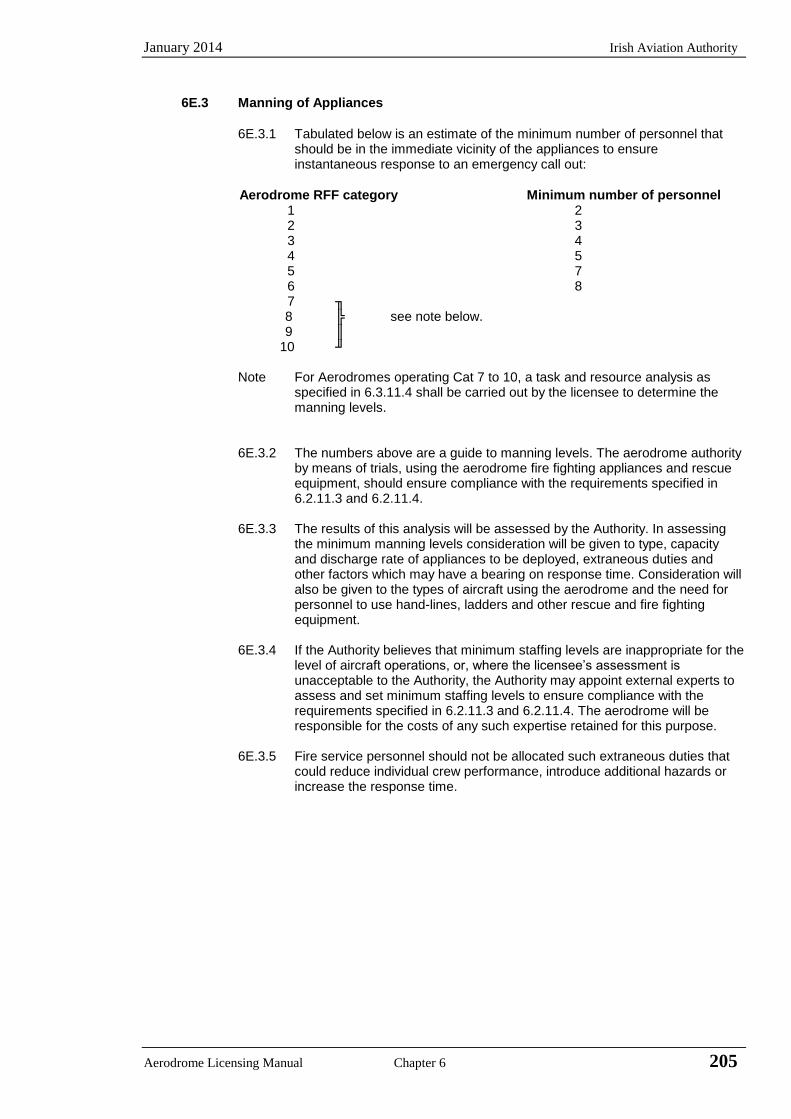
January 2014 Irish Aviation Authority
Aerodrome Licensing Manual Chapter 6 205
6E.3 Manning of Appliances
6E.3.1 Tabulated below is an estimate of the minimum number of personnel that
should be in the immediate vicinity of the appliances to ensure instantaneous response to an emergency call out:
Aerodrome RFF category Minimum number of personnel 1 2 2 3 3 4 4 5 5 7 6 8 7 ╖ 8 ╠ see note below. 9 ║ 10 ╜
Note For Aerodromes operating Cat 7 to 10, a task and resource analysis as specified in 6.3.11.4 shall be carried out by the licensee to determine the manning levels.
6E.3.2 The numbers above are a guide to manning levels. The aerodrome authority by means of trials, using the aerodrome fire fighting appliances and rescue equipment, should ensure compliance with the requirements specified in 6.2.11.3 and 6.2.11.4.
6E.3.3 The results of this analysis will be assessed by the Authority. In assessing
the minimum manning levels consideration will be given to type, capacity and discharge rate of appliances to be deployed, extraneous duties and other factors which may have a bearing on response time. Consideration will also be given to the types of aircraft using the aerodrome and the need for personnel to use hand-lines, ladders and other rescue and fire fighting equipment.
6E.3.4 If the Authority believes that minimum staffing levels are inappropriate for the
level of aircraft operations, or, where the licensee’s assessment is unacceptable to the Authority, the Authority may appoint external experts to assess and set minimum staffing levels to ensure compliance with the requirements specified in 6.2.11.3 and 6.2.11.4. The aerodrome will be responsible for the costs of any such expertise retained for this purpose.
6E.3.5 Fire service personnel should not be allocated such extraneous duties that
could reduce individual crew performance, introduce additional hazards or increase the response time.

Irish Aviation Authority January 2014
206 Chapter 6 Aerodrome Licensing Manual
Intentionally Blank
January 2014 Irish Aviation Authority
Aerodrome Licensing Manual Chapter 7 207
CHAPTER 7 GENERAL SERVICES
7.1 Disabled Aircraft Removal
7.1.1 A plan for the removal of an aircraft disabled on, or adjacent to, the movement area should be established for an aerodrome, and a co-ordinator designated to implement the plan, when necessary.
Note: 1. When a reportable incident or accident occurs, except for the reasons specified in
the Air Navigation (Investigation of Accidents) Regulations, (SI 460 of 2009), the aircraft / wreckage should be left undisturbed until the Investigator-in-Charge of the accident/incident grants permission for the removal of the aircraft / wreckage. Detailed guidance on the initial action at the scene of an accident, preservation of evidence, etc. may be found in the Manual of Air Accident Investigation. 2. Guidance on removal of a disabled aircraft, including recovery equipment, is given in the Airport Services Manual (Doc 9137), Part 5.
7.1.2 The disabled aircraft removal plan should be based on the characteristics of the
aircraft that may normally be expected to operate at the aerodrome and include among other things:
a) A list of equipment and personnel on, or in the vicinity of the aerodrome which
would be available for such purpose; and b) Arrangements for the rapid receipt of aircraft recovery equipment kits available
from other aerodromes.
7.2 Maintenance: General
7.2.1 A maintenance programme, including preventive maintenance where appropriate,
should be established at an aerodrome to maintain facilities in a condition which does not impair the safety, regularity or efficiency of air navigation.
Notes 1 Preventive maintenance is programmed maintenance work done in order to prevent
a failure or degradation of facilities. 2 “Facilities” are intended to include such items as pavements, visual aids, fencing,
drainage systems and buildings.
7.2.2 The design and application of the maintenance programme should observe Human Factors principles.
Note: Guidance material on human factors principles can be found in the Human Factors
Training Manual, Doc 9683, and in the Airport Services Manual (Doc 9137), Part 8.
7.3 Pavements
7.3.1 The surface of all movement areas including pavements (runways, taxiways,
aprons, and adjacent areas) shall be inspected and their conditions monitored regularly as part of an aerodrome preventive and corrective maintenance programme with the objective of avoiding and eliminating any loose objects/debris that might cause damage to aircraft or impair the operation of aircraft systems.
Notes: 1 See 1.3.8.3 for inspections of movement areas. 2 Guidance for carrying out daily inspections of the movement area is given in
Airport Services Manual, Part 8, Manual of Surface Movement Guidance and Control Systems (SMGCS) and the Advanced Surface Movement Guidance and Control Systems (A-SMGCS) Manual.
3 Additional guidance on sweeping/cleaning of surfaces is contained in the Airport Services Manual, Part 9.
Irish Aviation Authority January 2014
208 Chapter 7 Aerodrome Licensing Manual
4 Guidance on precautions to be taken in regard to the surface of shoulders is given in Attachment A, Section 9, and the Aerodrome Design Manual (Doc 9157), Part 2.
5. Where the pavement is used by large aircraft or aircraft with tire pressures in the upper categories referred to in Appendix 2A2.6 c), particular attention should be given to the integrity of light fittings in the pavement and pavement joints
7.3.2 The surface of a runway should be maintained in a condition such as to prevent
formation of harmful irregularities.
Note: See Annex 14, Attachment A Section 5.
7.3.3 A paved runway shall be maintained in a condition so as to provide surface friction characteristics at or above the minimum friction level specified in Chapter 2, Table 2.3.
Note The Airport Services Manual (Doc 9137), Part 2, contains further information on this subject, on improving surface friction characteristics of runways.
7.3.4 Runway surface friction characteristics for maintenance purposes shall be
periodically measured with a continuous friction measuring device using self-wetting features and documented. The frequency of these measurements shall be sufficient to determine the trend of the surface friction characteristics of the runway.
Notes 1 Guidance on evaluating the friction characteristics of a runway is provided in
Annex 14, Attachment A, Section 7. Additional guidance is included in the Airport Services Manual (Doc 9137), Part 2. 2 The objective of 7.3.2 to 7.3.5 is to ensure that the surface friction characteristics for the entire runway remain at or above a minimum friction level specified in Chapter 2, Table 2.3. 3 Guidance for the determination of the required frequency is provided in Attachment A, Section 7 and in the Airport Services Manual (Doc 9137), Part 2, Appendix 5.
7.3.5 Corrective maintenance action shall be taken when the friction characteristics
for either the entire runway or a portion thereof are below a minimum friction level specified in Chapter 2, Table 2.3.
Notes: A portion of the runway in the order of 100 m long may be considered significant for maintenance or reporting action
7.3.6 Corrective maintenance action should be considered when the friction
characteristics for either the entire runway or a portion thereof are below a maintenance planning level specified in Chapter 2, Table 2.3.
7.3.7 When there is a reason to believe that the drainage characteristics of a runway,
or portions thereof, are poor due to slopes or depressions, then the runway friction characteristics should be assessed under natural or simulated conditions that are representative of local rain and corrective maintenance should be taken as necessary.
7.3.8 When a taxiway is used by turbine-engined aeroplanes, the surface of the
taxiway shoulders should be maintained so as to be free of any loose stones or other objects that could be ingested by the aeroplane engines.
7.3.9 The surface of a paved runway shall be maintained in a condition so as to
provide good friction characteristics and low rolling resistance. Snow, slush, ice, standing water, mud, dust, sand, oil, rubber deposits and other contaminants shall be removed as rapidly and as completely as possible to minimise accumulation.
January 2014 Irish Aviation Authority
Aerodrome Licensing Manual Chapter 7 209
Note: The above requirement does not imply that winter operations on compacted snow and ice are prohibited. Guidance on snow removal and ice control and removal of other contaminants is given in the Aerodrome Services Manual (Doc 9137), Parts 2 and 9.
7.3.10 Taxiways should be kept clear of snow slush, ice, etc., to the extent necessary
to enable aircraft to be taxied to and from an operational runway.
7.3.11 Aprons should be kept clear of snow slush, ice, etc., to the extent necessary to enable aircraft to manoeuvre safely or, where appropriate to be towed or pushed.
7.3.12 Whenever the clearance of snow, slush, ice, etc., from the various parts of the
movement area cannot be carried out simultaneously, the order of priority after the runway(s) in use should be set in consultation with the affected parties such as rescue and fire fighting service and documented in a snow plan.
Notes 1 See Annex 15, Appendix 1, Part 3, AD 1.2.2 for information to be promulgated in an AIP concerning a snow plan. The Aeronautical Information Services Manual (Doc 8126), Chapter 5 contains guidance on the description of a snow plan including general policy concerning operational priorities established for the clearance of movement areas. 2 The Airport Services Manual (Doc 9137), Part 8, Chapter 6, specifies that an aerodrome snow plan clearly defines, inter alia, the priority of surfaces to be cleared.
7.3.13 Chemicals to remove or prevent the removal of ice and frost on aerodrome pavements should be used when conditions indicate their use could be effective. Caution should be exercised in the application of the chemicals so as not to create a more slippery condition.
Note: Guidance on the use of chemicals for aerodrome pavements is given in the Airport Services Manual, Part 2 (Doc 9137).
7.3.14 Chemicals which may have harmful effects on aircraft or pavements, or
chemicals which may have toxic effects on the aerodrome environment shall not be used.
7.4 Runway pavement overlays
Note: The following specifications are intended for runway pavement overlay projects when the runway is to be returned to an operational status before the overlay of the entire runway is complete thus normally necessitating a temporary ramp between the new and old runway surfaces. Guidance on overlaying pavements and assessing their operational status is given in the Aerodrome Design Manual, Part 3 (Doc 9157).
7.4.1 The longitudinal slope of the temporary ramp, measured with reference to the
existing runway surface or previous overlay course, shall be;
a) 0.5 to 1.0 per cent for overlays up to and including 5 cm in thickness. b) not more than 0.5% for overlays more than 5cm in thickness.
7.4.2 Overlaying should proceed from one end of the runway toward the other end so
that based on runway utilisation most aircraft operations will experience a down ramp.
7.4.3 The entire width of the runway should be overlaid during each work session. 7.4.4 Before a runway being overlaid is returned to temporary operational status, a
runway centre line marking conforming to the specifications in 4.5.2 shall be
Irish Aviation Authority January 2014
210 Chapter 7 Aerodrome Licensing Manual
provided. Additionally, the location of any temporary threshold shall be identified by a 3.6m wide transverse stripe.
7.4.5 The overlay should be constructed and maintained above the minimum friction
level specified in Table 2.3.
7.5 Wildlife Strike Hazard Reduction
Note The presence of wildlife (birds and animals) on and in the airport vicinity poses
a serious threat to aircraft operational safety.
7.5.1 The wildlife strike hazard on, or in the vicinity of, an aerodrome shall be assessed through: a) the establishment of a procedure for recording and reporting wildlife
strikes to aircraft; b) the collection of information from aircraft operators, airport personnel,
and other sources on the presence of wildlife on or around the aerodrome constituting a potential hazard to aircraft operations; and
c) an ongoing evaluation of the wildlife hazard by competent personnel.
Note See Annex 15, Chapter 8.
7.5.2 Wildlife strike reports shall be collected and forwarded to the National Bird Hazard Committee, who will undertake statistical analysis and forward data to ICAO for inclusion in the ICAO Bird Strike Information System (IBIS) database.
Note: The IBIS is designed to collect and disseminate information on wildlife strikes to
aircraft. Information on the system is included in the Manual on the ICAO Bird Strike Information System (IBIS)(Doc 9332).
7.5.3 Action shall be taken to decrease the risk to aircraft operations by adopting measures to minimize the likelihood of collisions between wildlife and aircraft.
Note: Guidance on effective measures for establishing whether or not wildlife, on or
near an aerodrome, constitute a potential hazard to aircraft operations, and on methods for discouraging their presence, is given in the Airport Services Manual, Part 3 (Doc 9137).
7.5.4 The aerodrome authority shall take action to eliminate or to prevent the establishment of garbage disposal dumps or any other source which may attract wildlife to the aerodrome, or its vicinity, unless an appropriate wildlife assessment indicates that they are unlikely to create conditions conducive to a wildlife hazard problem. Where the elimination of existing sites is not possible,
the aerodrome authority shall ensure that any risk to aircraft posed by these sites is assessed and reduced to as low as reasonably practicable.
7.5.5 Aerodrome Operators should give due consideration to aviation safety concerns
related to land developments in the vicinity of the aerodrome that may attract wildlife as part of the Aerodrome’s safeguarding policy.
7.6 Apron Management
7.6.1 When warranted by the volume of traffic and operating conditions, an
appropriate apron management service should be provided on the apron by an aerodrome ATS unit, by another aerodrome operating authority, or by a co-operative combination of these, in order to:
a) regulate movement with the objective of preventing collisions between
aircraft and between aircraft and obstacles;

January 2014 Irish Aviation Authority
Aerodrome Licensing Manual Chapter 7 211
b) regulate the entry of aircraft into, and co-ordinate exit of aircraft from, the apron with the aerodrome control tower; and
c) ensure safe and expeditious movement of vehicles and appropriate regulation of other activities.
7.6.2 When the aerodrome control tower does not participate in the apron
management service, procedures should be established to facilitate the orderly transition of aircraft between the apron management unit and the aerodrome control tower.
Note: Guidance on an apron management service is given in the Airport Services
Manual, Part 8 (Doc 9137) and the Manual of Surface Movement Guidance and Control Systems (Doc 9476).
7.6.3 An apron management service shall be provided with radio-telephony
communications facilities.
7.6.4 Where low visibility procedures are in effect, persons and vehicles operating on the apron shall be restricted to the essential minimum.
Note: Guidance on related special procedures is given in the Manual of Surface
Movement Guidance and Control Systems (Doc 9476).
7.6.5 An emergency vehicle responding to an emergency shall be given priority over all other surface movement traffic.
7.6.6 A vehicle operating on an apron shall:
a) give way to an emergency vehicle, an aircraft taxiing, about to taxi or
being pushed or towed; and b) give way to other vehicles in accordance with local regulations.
7.6.7 An aircraft stand shall be visually monitored to ensure that the recommended
clearance distances are provided to aircraft using the stand.
7.7 Ground Servicing of Aircraft
7.7.1 Fire extinguishing equipment suitable for at least initial intervention in the event of a fuel fire and personnel trained in its use shall be readily available during the ground servicing of an aircraft, and there shall be a means of quickly summoning the rescue and fire fighting service in the event of a fire or a major fuel spill.
7.7.2 When aircraft refuelling operations take place while passengers are embarking,
onboard or disembarking, ground equipment shall be positioned so as to allow:
a) the use of a sufficient number of exits for expeditious evacuation; and b) a ready escape route from each of the exits to be used in an emergency. c) unobstructed access for rescue and fire-fighting vehicles.
Note: Guidance on aircraft refuelling procedures is given in Airport Services Manual,
Part (Doc 9137).
7.8 Security
7.8.1 In accordance with the International Standards and Recommended Practices,
specified in Annex 17 - Security, the State has established a National Civil Aviation Security Programme. The purpose of this programme is to protect the safety, regularity and efficiency of civil aviation by providing through regulations, practices and procedures, safeguards against acts of unlawful interference. The
Irish Aviation Authority January 2014
212 Chapter 7 Aerodrome Licensing Manual
development, implementation and maintenance of the programme are vested directly in appropriate authorities and compliance is a condition of the licence.
7.8.2 A fence or other suitable barrier should be provided on an aerodrome: to
prevent the entrance to the movement area of animals large enough to be a hazard to aircraft.
7.8.3 A fence or other suitable battier should be provided on an aerodrome to deter
the inadvertent or premeditated access of an unauthorised person onto a non-public area of the aerodrome.
Notes: 1 This is intended to include the barring of sewers, ducts, tunnels, etc. where
necessary to prevent access. 2 Special measures may be required to prevent the access of an unauthorised
person to runways or taxiways which overpass public roads.
7.8.4 Suitable means of protection should be provided to deter the inadvertent or premeditated access of unauthorised persons into ground installations and facilities essential for the safety of civil aviation located off the aerodrome.
7.8.5 The fence or barrier should be located so as to separate the movement area
and other facilities or zones on the aerodrome vital to the safe operation of aircraft from areas open to public access.
7.8.6 When greater security is thought necessary, a cleared area should be provided
on both sides of the fence or barrier to facilitate the work of patrols and to make trespassing more difficult. Consideration should be given to the provision of a perimeter road inside the aerodrome fencing for the use of both maintenance personnel and security patrols.
7.8.7 At an aerodrome where it is deemed desirable for security reasons, a fence or
other barrier provided for the protection of international civil aviation and its facilities should be illuminated at a minimum essential level. Consideration should be given to locating lights so that the ground area on both sides of the fence or barrier, particularly at access points, is illuminated.
7.9 Siting of Equipment and Installations on Operational Areas
7.9.1 Unless its function requires it to be there for air navigation purposes, no equipment or installation shall be:
a) on a runway strip, a runway end safety area, a taxiway strip or within the
distances specified in Table 2.8, column 11, if it would endanger an aircraft; or
b) on a clearway if it would endanger an aircraft in the air.
7.9.2 Any equipment or installation required for air navigation purposes which must be located:
a) on that portion of a runway strip within:
1) 75 m of the runway centre line where the code number is 3 or 4; or 2) 45 m of the runway centre line where the code number is 1 or 2; or
b) on a runway end safety area, a taxiway strip or within the distances
specified in Table 2.8; or c) on a clearway which would endanger an aircraft in the air;
shall be frangible and mounted as low as possible.
January 2014 Irish Aviation Authority
Aerodrome Licensing Manual Chapter 7 213
7.9.3 Any equipment or installation required for air navigation purposes which must be located on the non-graded portion of a runway strip should be regarded as an obstacle and should be frangible and mounted as low as possible.
7.9.4 Unless its function requires it to be there for air navigation purposes, no
equipment or installation shall be located within 240 m of the end of the strip and within:
a) 60 m of the extended centre line where the code number is 3 or 4; or b) 45 m of the extended centre line where the code number is 1 or 2;
of a precision approach runway category I, II or III.
7.9.5 Any equipment or installation required for air navigation purposes which must be located on or near a strip of a precision approach runway category I, II or III and which:
a) is situated on that portion of a strip within 77.5 m of the runway centre
line where the code number is 4 and the code letter is F; or b) is situated within 240 m from the end of the strip and within:
1) 60 m of the extended centre line of the runway where the code
number is 3 or 4; or 2) 45 m of the extended runway centre line where the code number is 1
or 2; or c) penetrates the inner approach surface, the inner transitional surface or
the balked landing surface;
shall be frangible and mounted as low as possible.
7.9.6 Any equipment or installation required for air navigation purposes and which is an obstacle of operational significance in accordance with 5.3.2.4, 5.3.3.5, 5.3.4.9 and 5.3.5.6 should be frangible and mounted as low as possible.
7.10 Aerodrome Vehicle Operations
7.10.1 There is a need for ground vehicles to operate on the movement area for the
purposes of aircraft servicing, aerodrome maintenance and construction work and emergency operations. There are however a number of measures that may be taken to lessen the amount of mixing of aircraft and ground vehicles. Guidance on these measures is contained in the Aerodrome Design Manual, Part 2 (Doc 9157), which include:
a) exclusion: all ground vehicles whose function does not require them to
be on the movement area should be excluded;
b) service roads for ground vehicles: airside service roads for ground vehicles can eliminate or lessen to a great extent the necessity for the use of runways and taxiways by ground vehicles. Such roads should be planned so that at least the critical sections of the movement area for traffic congestion can be bypassed by ground vehicular traffic. For example, these roads may be used as aerodrome perimeter service roads providing access to navigation aids, as temporary roads for construction vehicles or as airside roads between terminal buildings and aprons for the passage of airline vehicles, baggage trains, etc. Every effort should be made to plan airside service roads so that they do not cross runways and taxiways;
c) fixed servicing installations: many apron service vehicles can be
eliminated with the provision of fixed service installations set either within
Irish Aviation Authority January 2014
214 Chapter 7 Aerodrome Licensing Manual
the apron or within the terminal buildings adjacent to the aircraft stands; and
d) markings: paint markings may be used to facilitate the segregation of
traffic on the apron.
7.10.2 A vehicle shall be operated:
a) on a manoeuvring area only as authorised by the aerodrome control tower; and
b) on an apron only as authorised by the appropriate designated authority.
Notes: 1. Guidance on aerodrome vehicle operation is contained in Annex 14; Attachment A, Section 18 and guidance on traffic rules and regulations for vehicles is contained in the Manual of Surface Movement Guidance and Control (SMGCS) (Doc 9476).
2. It is intended that roads located on the movement area be restricted to the
exclusive use of aerodrome personnel and other authorised persons, and that access to the public buildings by an unauthorised person will not require use of such roads.
7.10.3 The driver of a vehicle on the movement area shall comply with all mandatory
instructions conveyed by markings and signs unless otherwise authorised by:
a) the aerodrome control tower when on the manoeuvring area; or b) the appropriate designated authority when on the apron; and
7.10.4 The driver of a vehicle on the movement area shall comply with all mandatory
instructions conveyed by lights. 7.10.5 The driver of a vehicle on the movement area shall be appropriately trained for
the tasks to be performed and shall comply with the instructions issued by:
a) the aerodrome control tower when on the manoeuvring area; and b) the appropriate designated authority when on the apron.
7.10.6 The driver of a radio-equipped vehicle shall establish satisfactory two-way radio communication with the aerodrome control tower before entering the manoeuvring area and with the appropriate designated authority before entering the apron. The driver shall maintain a continuous listening watch on the assigned frequency when on the movement area.
7.10.7 The authorities responsible for the operation of vehicles on the movement area
should ensure that the operators are properly qualified. This may include, as appropriate to the driver’s function, a knowledge of:
a) the geography of the aerodrome; b) aerodrome signs, markings and lights; c) radiotelephone operating procedures; d) terms and phrases used in aerodrome control including the ICAO spelling
alphabet; e) rules of air traffic services as they relate to ground operations; f) airport rules and procedures; and g) specialist skills as required, for example in rescue and fire fighting.
7.10.8 The operator should be able to demonstrate competency, as appropriate, in;
a) the operation or use of vehicle transmit/receive equipment; b) understanding and complying with air traffic control and local procedures;
January 2014 Irish Aviation Authority
Aerodrome Licensing Manual Chapter 7 215
c) vehicle navigation on the aerodrome; and d) special skills required for the particular function.
In addition as required for any specialist function, the operator should be the
holder of a State driver’s licence, a State radio operator’s licence or other licences.
7.10.9 If special procedures apply for operations in low visibility conditions it is
desirable to verify an operator’s knowledge of procedures through periodic checks.
7.11 Surface Movement Guidance and Control Systems
7.11.1 In the broadest sense, a surface movement guidance and control system
(SMGCS) consists of guidance to, and control or regulation of, all aircraft, ground vehicles and personnel on the movement area of an aerodrome. ‘Guidance’ relates to facilities, information and advice necessary to enable the pilots of aircraft or the drivers of ground vehicles to find their way on an aerodrome and to keep the aircraft or vehicles on the surfaces or within the areas intended for their use. ‘Control or regulation’ means the measures necessary to prevent collisions and to ensure that traffic flows freely.
7.11.2 A SMGCS comprises an appropriate combination of visual aids, non-visual
aids, procedures, control, regulation, management and information facilities. Systems range from the very simple at small aerodromes, with light traffic operating in good visibility conditions, to the complex systems necessary at large aerodromes with heavy traffic operating in low visibility conditions. The system selected for an aerodrome will be appropriate to the operational environment in which the aerodrome will operate.
7.11.3 Because of the multi-disciplinary interests in a SMGCS there is a need to co-
ordinate fully all current and planned use of a SMGCS to ensure compatibility with aerodrome engineering, operations, communications, aerodrome air traffic control service, operators and pilot requirements.
7.11.4 A surface movement guidance and control system shall be provided at an
aerodrome.
Note Guidance on surface movement’s guidance and control systems is contained in the Manual of Surface Movement Guidance and Control Systems (SMGCS) (Doc 9476).
7.11.5 The design of a SMGCS system should take into account:
a) the density of air traffic; b) the visibility conditions under which operations are intended; c) the need for pilot orientation; d) the complexity of the aerodrome layout; and e) movements of vehicles.
7.11.6 The visual aid components of a SMGCS, i.e. lights and markings, signs and
markers should be designed to conform with the relevant specifications in Chapters 3 and 4.
7.11.7 A SMGCS should be designed to assist in the prevention of inadvertent
incursions of aircraft and vehicles onto an active runway.
7.11.8 The system should be designed to assist in the prevention of collisions between aircraft, and between aircraft and vehicles or objects, on any part of the movement area.
Irish Aviation Authority January 2014
216 Chapter 7 Aerodrome Licensing Manual
Note: Guidance on control of stop bars through induction loops and on a visual taxiing guidance and control system is contained in the Aerodrome Design Manual, Part 4 (Doc 9157).
7.11.9 Where a SMGCS is provided by selective switching of stop bars and taxiway
centre line lights; the following requirements shall be met;
a) taxiway routes which are indicated by illuminated taxiway centre line lights shall be capable of being terminated by an illuminated stop bar;
b) the control circuits shall be so arranged that when a stop bar located ahead of an aircraft is illuminated the appropriate section of taxiway centre line lights beyond it is suppressed; and
c) the taxiway centre line lights are activated ahead of an aircraft when the stop bar is suppressed.
Notes: 1 See Chapter 3 for specifications on taxiway centre line lights and stop bar
lights respectively. 2 Guidance on installation of stop bars and taxiway centre line lights in a
SMGCS is given in the Aerodrome Design Manual, Part 4 (Doc 9157).
7.11.10 Surface movement radar for the manoeuvring area should be provided at an aerodrome intended for use in RVR conditions less than a value of 350 m.
7.11.11 Surface movement radar for the manoeuvring area should be provided at an
aerodrome other than in 7.11.10 when traffic density and operating conditions are such that regularity of traffic flow cannot be maintained by alternative procedures and facilities.
Note Guidance on the use of surface movement radar is given in the Manual of
SMGCS and in the Air Traffic Services Planning Manual (Doc. 9426).
January 2014 Irish Aviation Authority
Aerodrome Licensing Manual Chapter 8 217
CHAPTER 8 AERODROME MANUAL, SAFETY MANAGEMENT SYSTEM 8.1 General 8.1.1 Prior to granting the aerodrome licence, an Aerodrome Manual shall be submitted by
the applicant which will include all pertinent information on the aerodrome site, facilities, services, equipment, operating procedures, organization and management including a safety management system. The Aerodrome Manual shall conform to the requirements specified in aeronautical Notice T.04. The aerodrome licensee shall be responsible for maintaining the currency of the aerodrome manual for the duration of the aerodrome licence.
Note The intent of a safety management system is to have in place an organized and
orderly approach in the management of aerodrome safety by the aerodrome operator. Annex 19 — Safety Management contains the safety management provisions applicable to certified aerodromes. Guidance on an aerodrome safety management system is given in the Safety Management Manual (SMM) (Doc 9859) and in the Manual on Certification of Aerodromes (Doc 9774).
8.1.2 Aerodrome operators shall establish a safety programme in order to achieve an acceptable level of safety in aerodrome operations.
8.1.3 As part of their safety programme, a certified aerodrome operator shall implement a
safety management system that:
a) identifies safety hazards;
b) ensures the implementation of remedial action necessary to maintain agreed safety performance;
c) provides for continuous monitoring and regular assessment of the safety performance; and
d) aims at a continuous improvement of the overall performance of the safety management system.
Note: Further information on safety management at public licensed aerodromes is contained in Aeronautical Notice T.08.
8.1.4 The safety management system shall clearly define lines of safety accountability throughout a certified aerodrome including a direct accountability for safety on the part of senior management.
Irish Aviation Authority January 2014
218 Chapter 8 Aerodrome Licensing Manual
Appendix 8A Framework for Safety Management Systems (SMS)
8A.1 General 8A.1.1 The framework includes four components and twelve elements representing
the minimum requirements for SMS implementation. The implementation of the framework shall be commensurate with the size of the organization and the complexity of the services provided. The Authority is available for consultation in relation to any aspects of the development of the SMS.
8A.2 Safety policy and objectives 8A.2.1 Management commitment and responsibility
The certified aerodrome authority shall define the organisation’s safety policy which shall be signed by the accountable executive of the organisation. The safety policy shall reflect organizational commitments regarding safety; shall include a clear statement about the provision of the necessary resources for the implementation of the safety policy; and shall be communicated, with visible endorsement, throughout the organisation. The safety policy shall include the safety reporting procedures; shall clearly indicate which types of operational behaviours are unacceptable; and shall include the conditions under which disciplinary action would not apply. The safety policy shall be periodically reviewed to ensure it remains relevant and appropriate to the organisation.
8A.2.2 Safety accountabilities
The certified aerodrome authority shall identify the accountable executive who, irrespective of other functions, shall have ultimate responsibility and accountability, on behalf of the certified aerodrome, for the implementation and maintenance of the SMS. The certified aerodrome shall also identify the accountabilities of all members of management, irrespective of other functions, as well as of employees, with respect to the safety performance of the SMS. Safety responsibilities, accountabilities and authorities shall be documented and communicated throughout the organisation, and shall include a definition of the levels of management with authority to make decisions regarding safety risk tolerability.
8A.2.3 Appointment of key safety personnel
The certified aerodrome authority shall identify a safety manager to be the responsible individual and focal point for the implementation and maintenance of an effective SMS.
8A.2.4 Co-ordination of emergency response planning
The certified aerodrome authority shall ensure that an emergency response plan that provides for the orderly and efficient transition from normal to emergency operations and the return to normal operation is properly coordinated with the emergency response plans of those organisations it must interface with during the provision of its services.

January 2014 Irish Aviation Authority
Aerodrome Licensing Manual Chapter 8 219
8A.2.5 SMS documentation
The certified aerodrome authority shall develop an SMS implementation plan, endorsed by senior management of the organization, which defines the organisation’s approach to the management of safety in a manner that meets the organisation’s safety objectives. The organisation shall develop and maintain SMS documentation describing safety policy and objectives, the SMS requirements, the SMS processes and procedures, the accountabilities, responsibilities and authorities for processes and procedures, and the SMS outputs. Also as part of the SMS documentation, the certified aerodrome shall develop and maintain a safety management system’s manual (SMSM), to communicate its approach to the management of safety throughout the organisation.
8A.3 Safety risk management 8A.3.1 Hazard identification
The certified aerodrome authority shall develop and maintain a formal process that ensures that hazards in operations are identified. Hazard identification shall be based on a combination of reactive, proactive and predictive methods of safety data collection.
8A.3.2 Safety risk assessment and mitigation
The certified aerodrome authority shall develop and maintain a formal process that ensures analysis, assessment and control of the safety risks in aerodrome operations.
8A.4 Safety assurance 8A.4.1 Safety performance monitoring and measurement
The certified aerodrome authority shall develop and maintain the means to verify the safety performance of the organisation, and to validate the effectiveness of safety risk controls. The safety performance of the organisation shall be verified in reference to the safety performance indicators and safety performance targets of the SMS.
8A.4.2 The management of change
The certified aerodrome authority shall develop and maintain a formal process to identify changes within the organisation which may affect established processes and services; to describe the arrangements to ensure safety performance before implementing changes; and to eliminate or modify safety risk controls that are no longer needed or effective due to changes in the operational environment.
8A.4.3 Continuous improvement of the SMS
The certified aerodrome authority shall develop and maintain a formal process to identify the causes of substandard performance of the SMS, determine the implications of substandard performance of the SMS in operations, and eliminate or mitigate such causes.
Irish Aviation Authority January 2014
220 Chapter 8 Aerodrome Licensing Manual
8A.5 Safety promotion 8A.5.1 Training and education
The certified aerodrome authority shall develop and maintain a safety training programme that ensures that personnel are trained and competent to perform the SMS duties. The scope of the safety training shall be appropriate to each individual’s involvement in the SMS.
8A.5.2 Safety communication
The certified aerodrome authority shall develop and maintain formal means for safety communication that ensures that all personnel are fully aware of the SMS, conveys safety critical information, and explains why particular safety actions are taken and why safety procedures are introduced or changed.