
i i - NASA · sneak circuit analysis based on Apollo experience but is ... Apoll9 sneak circuit...
59
. ; � ; ,i ' . I : ? I . . I ' I I I � � t ; : 11 11 . I ' · . : j I I I : '_ · f r ; I d J , . i l l � i I t! ! It , l ! I I I · . . , , ' ' I i; I' i i I . . � . i I , _ . I ' I h ! \ I i t . . \ . 02-11S41-1 SNEAK CIRCUIT ANALYSIS HANDBOOK i . . ' E IING cNv HOUSTON, TEXAS 15 JULY 1970 . . _ t :( -,
Transcript of i i - NASA · sneak circuit analysis based on Apollo experience but is ... Apoll9 sneak circuit...

.. .
; � ; ,i ' .I: ? I
. . I ' I I I
� �
t;: 1111 . I' · . : j I II : '_· f r ; I
d J ,. ill � i I t! ! It , l! I I
I · . . , , ''I i; I'
ii I
. .
�. i I,_. I ' I
h !\I it
.... \ .
02-118341-1
SNEAK CIRCUIT ANALYSIS HANDBOOK i . . '
E IIIIIING cOM.-.Nv HOUSTON, TEXAS
15 JULY 1970
.... _
t :(
-,

•
•
•
• ...
•
CODE !DENT. NO. £s 1205
NUMBER 02·118341-1 DRL 88 (T-587)
-�- -- - � --- �--
REV LTR
MLE: --�SN:.:.=E"'--.A:.K .:.C�I R:.=.C:.:U I:;.:.T...:.A.:.:.:N:.::AL :..:.Y.:.:S I:..:S;...:H�A�ND::::B:;,;:;OO�K=------
MODEL APOLLO
ISSUE NO . ___ _
CONTRACT NAS9: 10364 ISSUED TO: _______ _
1
\ . ·. '
02·118341·1
: _.,... r:u:¢4#JJC44f#i41 . . It $4 4 45 44 ¢ J&&&& au
.,.. i
I
······"•• I
,'r

REVISIONS REV. DESCRIPTION DATE SYM
I
•
•
•
•
..
• •
•
..
•
.
v
.
2
'd[Qliii#AAtt.l Ui! x:: . . coc · r ·- ··· ··
,, v .�,
.. �--------
APPROVED
""
•·
.
92-118341-1

� I ; . I.
•
•
...
•
·�
•
ABSTRACT
The concepts of formal enginee�1ng analysis to detect, and thus prevent, sneak circuits are pre·sented. Sneak ci rcu1 ts are coiTIIlonly known as system "glitches .. or electrical anomalies which are not contingent on component failures. It has been found that such sneak circuits have distinct. classifiable characteristics which make engineering analysis feasible. these characteristics and methods for their recognition are disclosed herein •
KEY WORDS .. --Sneak Circuits
Pathfind i ng
Circuit Topology
Electrical/Electronic Analysis
Computerized Electrical System Analysis
Apollo SpJlcecraft An�lysis
Topological Analysis
Network Trees
Node Topographs
3
!'- . · ... .,., � --
' 02-118341-1
l I J.
I ' , '
I I I � : :.:. I '
..

TABLE OF CONTENTS
SECTION . REVISIONS
ABSTRACT • KEY WORDS
TABLE OF CONTENTS • ILLUSTRATIONS
• REFERENCES
1 .o INTRODUCTION
1 . 1 BACKGROUND
1.2. PURPOSE
1 .. 3 SCOPE
2.0 THEORY OF ANALYSIS
2.1 SNEAK ClRCUIT DEFINITlON .
2.2 SNEAK CIRCUIT EXAMPLE
2.3 CLASSIFICATION OF SNEAKJClRCUITS
2.4 ANALYTICAL TECHNIQUE
2.5 NODE TOPOGRAPHS ·
2.6 SNEAK CIRCUIT CLUES
2.6.1 Power-t�-Power Path
2.6.2 Ground-to-Ground Path
2.6.3 Rever se Current Flow
2.6 . 4 Multiple Controls
2.6.5 Relay Race
2 . 6.6 Ambiguou s Indicators .. 2 . 6 . 7 Misleading lab�1s •
• 3.0 APPLICATION OF CONCEPTS
3.1 DATA 3.1.1 Data Requiremen�s
3.1. 2 Data Control
3.2 SYSTEM PARTITIONING
4
PAGE
2
3 3
4 - 5 6
7 - 8
9
9
10-
to
12
12
12
13
14
.16
11 17
18
18
19 20
20
21
22
22
22
24
24
92-118341�1
. ---" ... , ..
�· .::::
..-.
�� :i .; • '
.. + -� ! .......... . f "' -t
l

SECTION
3.2. 1
3.2.2
3 .2 .3
3 .2 . 4 •
3 .3
3.4 ..
3 .5
.. 3.6
3 .6 . 1
. . 3.6 . 1.1
3 .6 . 1 .2
3 .6 .2
3 .6 .2.1
3.6.2 .2
3.6.2.3
3.6 .2.4
3 .6 .2 .5
3.7
APPENDIX A .
.,
...
•
··• . '!!!fiJI I U I I 24 ; ,: A . r,· _ -� >4/._, 4 II!'A'i'-.h4 .' }jP(j
PAGE --
Upper Power Tree 25
Primary PO\oJer and Contro l 25
Secondary Powe r and Con tro l 25
Si gna l C i rcu i ts 25
NETWO RK TREES ?7
TREE ANALYSIS 29
SNEAK C I RCUIT ANALYS I S REPO RT ING 30
COMPUTER ASS I STANCE I N SNEAK C I RCUIT ANALYS I S 31
Automa ted Fi 11 ng... Program 31
AFP Mas terf il e lnfot"ma t ion 31
AFP Reports 32
Automa ted Sneak Program (ASP ) 33
ASP Inpu ts 33
ASP Processes 34
ASP Reports 34 -
ASP Tree-S ketchi ng Procedu re 36 *
Add i tion� l ASP Capabi l i t i e s 38 . - �
SUMMARY AND CONCLUSIONS 42 ····"'•·
APOLLO BID I NPUT GU IDELINES 45
5 02-118341- t

ILLUSTRATIONS
FIGURE · TITLE PAGE -
2- 1 Or i g i na l Sneak Cir cu i t Example 13
• 2-2 Example of Network Tree 15
2-3 E l ementary Node Topograohs 16
2-4 "H" Topograph/Reverse Current Dome 16 .. 2-5 Power - to-Power Sneak 17
.. 2-6 Ground-to-Ground Sneak 18
2-7 Reverse Current Sneak 19
• 2-8 Mul ti pl e Contro l Sneak 19
2-9 Relay Race Sneak 20
2-lO Amb 1 guou s . I radi c a tor Sneak 20
2-11 Mi s l eading Label Sneak 21
3- 1 Exampl e of System Par ti ti on ing 26
3-2 E lementary Trees 27
3-3 Typi ca l Tree 28
3-4 ' Mode Di agrams of Tree 29
3-5 Interre l ated Network Trees 30
3-6 H i gh Impedance Sub-Tree Par ti tions 37
3-7 Umbi l i cals on Tree 37 ;. '� ...
3-8 Load Symbol s for Tree Ske tches 39
3-9 Sneak C ircu i t Anal ysi s Wor.k Fl ow Diagram 44
A-1 B ID Input Sheet w1 th Typ i cal Bl �nd B2 Entri es 46 ''S I
A-2 Illustrati on of Shorti ng Swi tch 52 w �·
·A-3 Double-Pol e , Double-Throw Ganged Switch 53 <
""' '� '
-· A-4 Load Codi ng Example 54 � ... ' *
• A··5 Codi ng of Para l l e l Branches 56
A-6 Arc-Suppressed Relay Coil 57 •
6 02- 1 18341-1
, • �:: CZI!( R¥ PEJS 4 $(!$¢!Q IQU I ¥4 14$0(SXC4 ee .. IQA4#¥ SWSU: a;;( &jQ !SJS )I I, GW 2 S121 4¥l$#ji$Q:C)$1! 4464 ou ••

•
..
•
•
• •
REFERENCES
. J .. ',f;()U-P-018. "Plan, Apollo Spacecraft �neak Circuit Analysis". Contract No. NASW-1650, National Aeronautics and Space Admi nistration .
2. IJ�-118081-28 .. "Requirements for the Automated Sneak Program" - The Boeing Company.
), rJ�-118211-lA, "Automated Sneak Program System Document /Automated Sneak Program (ASP)" - The Boeing Company.
4. IJt'.-118212-1, "BID Preprocessor/Automated Sneoak Program (ASP)" -The Boeing Company .
f •1• IJ2 ... 118213-1, "North American Preprocessor/Automated Sneak Program (ASP)" - The Boe ing Company .
r,, 1)2-118214-1, "GSE Preprocessor/Automated Sneak Program (ASP)" - The Boe ing Company .
1. IJ2-l18215-1, "Grumman Preprocessor/Automated Sneak Program (ASP)" T he Boe i ng Company .
0. 02-118216-1, 11Grumman Pre-Preprop/Automated Sneak Program (ASP)'1 •
The Boeing Company .
9. 02-118217-1. " BED Update/Automa ted Sneak Program (ASP)" - The Boe i ng • °
Company .
10. D2-118218-l, " In l ine Di sconnect/Automa ted Sneak Program (ASP) -The Boe i ng Company .
11. 02-118219-1, "Merge BID/BED/Automated Sneak Program (ASP)" - The Boe i ng Company .
12. 02-118220-1, " B ranch/Cross Reference Tab l e/Automated Sneak Prog ram {ASP)" - T he Boeing Company
13. 02-118221-lA. " Pa th Deri vation/Automated Sneak Program (ASP)" - T he � Boei ng Company .
0
14. 02-118222-lA, "Regeneration-1/Automa ted Sneak Program (ASP)" - T he . Boeing Company •
15. D2�11S223-1A, "RECFIX/AL•tomated Sneak Program (ASP)" - The Boei ng Company .
7 02·118341-1
I I '·:-I C;t UU41'Jlf4 144414 ,,;;,n 0 l M14¥ I ¥¥f.i#4P# •. ,¥¥ .' ;;; .I UP,C.MMJ$4 4.1 ijll. iJ¥1 i' 0'44 I a, II ;;gay;a;:;o)JJII04 'f .• f
.\

16. D2·118225-1A,
. 17. 02-118226-1A. •
18. 02-118227-lA, •
. . 19. 02-118228-1,
•
20. 02-118305-1,
21. 02•118306-1,
22. 02-118307-1,
23. 02-118308-1,
24. 02-118309-1.
25. 02-118243-1.
26 • 02-11"8209-1.
•
••
•
:;_ '• a --·papA a;: II Nil' :ys 4 _,14, "• 4 1411 Lu .. 7 .
- --- - ---- - --�----�---------.-
"Lega l Path Report/Automated Sneak Pr�Jgram (ASP" -The Boei ng Company,
"Node Report Data Generat ion/Automated Sneak Program (ASP ) " - The Boei ng Company,
" In tersect and Specia l Node Report and Control Sunvnary Report/Automated Sneak Program (ASP)" .. The Boeing Company .
"JSAM Tab l e Generator/Automated Sneak Program (ASP ) ,. -The Boeing Company •
..Path Redunda�cy/Automated Sneak Program (ASP11 -Tbe: .. Boei ng Company.
"Path Redundancy-1/Autumated Sneak Program (ASP)" -The Boeing Company.
11Intersect Node/Automated Sneak Program (ASP)" -The Boeing Company .
11 Sneak Utility Programs/ Automated Sneak Program (ASP) .. - The Boeing Company.
"Dioda/Load-Special Node/Automated Sneak Program (ASP)" - The Boeing Company.
..Automated Filing Program Requirements," - The Boeing Company. .
"Automated Filing Program {AFP)1" - The Boeing Company.
8 02-118341-1
·-·
---"'
�'ir·
. i � ! j i � I
t l t
I.

� ,- .. � . i '
�� � � ,f'•' J J r ,. ,
•
•
·-
•
•
•
..
•
1 .0 INTRODUCTION
1 .1
This handbook describes a sneak circuit analysis method and 1ts app l ica ti on to electrical or e l ec tronic systems. It i s i ntended for use in initiating a sneak circuit analysis task. If the a nalysis is to bC! aided by au tomated cireui t path tracing. then the handbook shou l d bP used in conjuncti on wi th the referenced computer program documents. The handbook is divided into three £ections. The i ntroductory section gives some of the his tory of Apollo sneak circu it analysis and scopes the types of circuits to which the ana� lys i s has been applied. In the next section. Theo ry , a . s neak circuit def i niti on and ensui ng d 1 s cvss 1 on l ead direct ly to some examples of known sneak ci rcui ts. A l so descri bed i s a method of reduci ng system comp l exity to achieve sel ective loss of deta i l for analyti cal pu rpcses . A new techn i que . topol og i cal recogni t ion , and i ts use as an analytica l tool i s d i s cussed , and the secti on i s concluded wi th recogni ti on cl ues to ass i s t the ana lyst i n searchi ng for sneak circuits .
The sect i on enti tl ed 11App l i cat i on11 re l ates the detai l s of s neak c ircui t ana lys is based on Apol lo experi ence but i s i ntended for general app l i catfon to any el ectri ca l or electron i c system . Schemat i c data systems and tracki ng of changes to assure current confi gurations are d i scussed . Data reduct ion to produce network trees and , subsequently. node topographs i s i l l ustrated . Analys i s of system operati ng modes and app l i cat i on of s neak circuit cl ues i s des cr i be d . The secti on i s ended w i th a descr i pt i on o f a new automated method of t raci ng through schemati c i nformati on to fi nd circui t paths--perhaps the most s i gnificant advance i n computer appl i cati on to e l ectr i cal/el ect roni c schemati c i nformation proces s i ng .
Background
Duri ng the Apol l o Lvnar Land i ng Program . offi cial s of the National Aeronauti cs and Space Admi ni s trat i on at the Manned Spacecraft Center i n Houston , Texas, recogn ized sneak ci rcui ts as a l atent type of el ectri cal hardware defi c iency wh i ch could destroy cr i ti cal equ i pment and endanger the astronaut
9 02-1 1 8341 - 1
,•''"•·

crew. According l y , a sneak circuit analysis task was imple� mented on Apollo in early 1968. A team of electrical and electronic ana lysts and data processing specialists was assigned the task of i dentifying sneak circuits in the Apol lo spacecraft. An additional goal established at the outset was to automate as much of the analysis as possible to remove human error and expedite results.
To date. the analysis has uncovered over 60 sneak circuits. most of which could be prevented by crew procedural changes. In addi tion . an operationa l computer program was deve loped to au tomatica l ly search out c ircu i t paths, thus el i mi na ting the burdensome and costly task of tracing from one schema ti c page to the o ther i n order to complete a circuit . As a byproduct, many schematic errors have been found through the use of thi s program.
The mater ia l conta i ned herei n is based who l ly on the experi ence gai ned duri ng the first two years of performi ng the Apo l l9 sneak circu i t analys i s taslc.
1 .2 Purpose
Thi s handbook has been prepared for the sol e purpose of maki ng avai labl e to al l agenci es the exper i ence and techniques gai ned from analys i s and development of sneak c ircu i t technology on Apol lo . It i s pr i mar i ly i ntended for the s neak circuit task manager and provi des an overa l l , yet detai l ed, descr i ption of the s neak circui t ana lys i s method and i ts app l i cation to electr i ca l or e l ectroni c systems . Fur ther , i t gi ves a baseli ne descr i ption o f the Automated Sneak Program (a computeri zed circu i t path fi nder ) wh i ch. i n conjunction wi th the referenced computer documents. may be used to i ni ti ate a computer-as s i s ted analys i s . The handbook may a l so be used by the ana lys t to get a c l ear unders tandir.g o f what a sneak circu i t i s and how to fi nd i t .
1 .3 Scope
T he scope of the handbook i ncl udes a deta i l ed descr ipti on of the theory. data . and methods requ ired to per form a sneak circu it analys i s . I t emphas i zes s neak c i rcuit i denti fi cation through the appl i catisn of topo logi cal c l ues . A general des cr i ption of the Automated Sneak Pro gram i s given.
10 02· 1 1 8341 - 1
•
.·· ··".

•
•
•
•
..
-- - ---------� -� ----�
The origi nal sneak circuit analysis pl an ( Reference 1 ) identified two types of sneak circuits; current sneaks and si gnal sneaks. Thi s hnndbook deal s predominately with current sneaks i n power and control circuitry . Applicati on of the methods to digital l og ic circui ts of computers is not the subject treated here i n even though in some cases l ogic gates and other l og ic e lements are i ncl uded as ch·cuit components initiating or inhibiting control functi ons .
•
1 1 02-1 1 8341 - 1

•
•
•
•
•
2.0 THEORY OF ANALYSIS
This secti on treats the theoreti ca l aspects that evo l ved d ur1ng the course of ana lys i s for sneak c ircu i ts on Apol l o. At the outset o f the analys i s , not even an accurate deftn 1� t i on of a sneak c i rcu i t ex i sted . Later , a genera l ly acceptable def i n i ti on and some c l ues for f i ndi ng s neak c i rcu i ts were establ i she d . The c lues were found emp i ri ca l l y . For exampl e , i t was noted that latent c i rcu it pa ths resu l ti ng from unusua l swi tch confi gura ti ons wh i ch connected two or more power busses or power sources together , often l ed to sneak c i rcui ts . In addi ti on , swi tch i ng modes that a l l owed curren t revers a 1 through one branch of a c i rcuit often caused a sneak c i rcu i t. These c l ues and others noted be low were analyzed i n and of themsel ves . The res u l t l ed di rectly to the fol l owi ng ana lyt i cal theory: E l ectri ca l and e l ectroni c c i rcu i ts , no matter how interconnected and i nterrelated , can be topol ogi ca l ly s i mp l i fi ed us i ng se l ecti ve l os s of deta i l . unti l certai n s neak c l ue patterns can be eas i ly recognized . Ana lysis of ci rcu i t operating characte ri s ti cs in the pattern is used to dete rmine sneak ci rcuit probabi l i ty .
As deta i l ed l ater i n th i s sect i on , some l atent anoma1ous ci rcu i t condi t i ons_.do not resu l t from sneak current paths but rather f rom i ncorrect c i rcui t ti mi ng. fa l se l abe l s on control s , and amb i guous or fal se i nd icati ons of sta tus on n�ters and other readout devi ces . Experi ence has shown that these l atent condi t i ons are a l so more eas i ly uncovered us ing topol og i cal s in� l i ficati on .
2.1 Sneak Ci rcu i t Defi ni tion
2.2
A sneak circuit 1s defined as a path that has i latent anomalous electrical condition resulting from an unapparent stimulus-response relationship which causes an unwanted function or inhibits a wanted function. It should be noted that the electrical condition includes not only electrical and electronic elements but also involves associated operator observations and resultant actions •
Sneak Ci rcui t Examp l e
The orig i na l examp l e prov i ded by NASA to i l l us trate a sneak circui t s hows how an apparently innocent-l ooking c i rcuit
12 02- 118341-l
.... p -'•"'"�' I #C .. '*"" CD. C 4 ;; i; � ' k-
· - ..
,.•''\• -r· .:
l t •
.·

•
•
•
•
•
� GROUND
can lead to a s igni fi cant fai l u re. The c i rcui t a s i l l ustrated i n Figure 2- 1 shows engine ON and OFF commands to a typ ical mi s si le or l aunch vehicle •
r.-- ........... J � ENG S OFF .
COIL LtJ-1!1�--....
SAFETY GROUND .
(TO PREVENT ACCIDENTAL ABORTS )
FIGURE 2�1. Original Sneak C i rcui t Example
The s neak path . as i ndi cate� by the arrows , occurs when the umbil i cal tai l p l ug pu l l s out before the fly- away umb i l i cal pul l s away . T h i s allows electri ca l current to flow in a . reverse di rection through the engi ne OFF coi l causing eng i ne c utoff to occur just after the veh i cl e has l i fted off the l aunch pad •
2.3 Clas s i fi cation o f Sneak Circuits
A sneak ci rcui t can be broken down i nto i ts consti tuent parts in o rder to bette r unders tand the vari ous pos s i bl e mean& by which it w i l l occur. Every s neak ci rcuit i nvo l ves a s timu l us, a path, and a response, and each of these component parts may
13 02-118341-1
� ........

•
•
•
•
•
· ..
be the initiator of an unintended action or function. The stimuli can be manual or automati c and include such actions as switch operations, relay transfers, logic enab l es , etc •
Paths always include electrical-electronic el ements permitting electrical energy flow but may al so require associated non-electrical energy forms for comp l etion. Response s include indications as well as subseque,,t functions wh,ch in turn may act as stimul i. Thus, a sneak circuit driving an indicator, say an abort light, can cause an unnecessary subsequent action which may have far-reaching consequences .
Sneak circuits may be r;lassified into four categories as an aid to analysis. The four categories are based on different sneak conditions whi ch may exist as follows:
1 . Sneak Path -A sneak path may cause current or energy to flow along an unexpected route.
2. Sneak Timing - Sneak timing may cause current or energy to flow or inhibit a fun ction at an unexpected time.
3 • . Sneak Indication - A sneak indication may cause an ambiguous or false display of system operating conditions.
4. Sneak Label - A sneak label m� cause incorrect stimuli to be initiated.
2.4 Analytical Technique
The basis of the sneak circuit analytical technique is topological simplification of circuitry to facilitate clue pattern recognition. Thus, the"first step requires that the system and.detail electrical schematics be simplified to basic circuit continuities showing power sources, nodes, switches. diodes, loads, and grounds. The circuit elements and interconnections are drawn in the fonn of a networ-k tree using selective loss· of detail to show only the important elements. The resultant sketch is not place-oriehted as are-most schematics. All extraneous infonnation is omitted including wiring data. component nomenclature . ..
14 02-118341·1
'•
- .
..·····l·

F
•
•
•
•
• ..
•
. .
and pl ug-jack i denti fi ca ti on . However. swi tch and c i rcu i t breaker l abel� a re i ncl uded and a l l p l ug-jack pa i rs that are interrupted (separated) as part of the no rmal mode of operation are shown as switches. Most importantly, all c i rcuit connecti ons must be shown to enab le �nalysis of the complete circuit and its i nteractions . Functional relations h i ps between c i rcu it components , such as re l ay coi l s in one network tree and the i r contacts in another tree, are noted for composite analys i s . Th i s ter.hnique reduces a c i rcu i t found on many pages of drawi ngs to a representati on on one sma l l sheet of paper , thus p rovi d i ng the sys tem overvi ew requi red for effect i ve analys i s .
I n i ti a l ly. a l l switches are s hown closed in each pos it ion , and the network tree thus i ncl udes a l l poss i b l e current fl ow paths . Later i n the ana lys i s , these switches wi l l be se l ect i vely "opened" to separate real c i rcui ts from those created by impossible swi tch confi gu rat i ons .
The type of network tree used for the analys i s i s i l lu s trated bel ow i n Figure 2-2.
CSM-106 NODAL SET 030
21 VOlt BAt RELAY BUS 0 � ICIIAISitiC,NUll
» C814, c 15- 4at\f0l • •
�--------------�N�· I
CM •t;
llti•&.VI ·
SLV2
CII•IAtQ liAR POl. BS1·1Cic
•
U. CZ2·2A20l EMER 1 NORMAL
FIGURE 2-2. Example of "�f!tWork Tree
15
Note: EMER and NORMAb positi ons of 53 cannot be closed simultaneous ly (impossible switch configuration) •
02-11834:• -1
....... l.tt.t 2£ 2 O�ZP iiPI=, $1Ei(QJ44 I --$11$) CMQ:U�;ewa:p. �� -· .-. '
.':. .. 1/\•, .... 1"''-<-.... . ' --- � - . . - � �( --· . , "·:��.:.,.·.:·��;;_._. ��--;��-�';: -�-:��-:.,�---d:���·�j- ���.<r··=�-- ;.__ �!- �" · ·, ... >-�- ,·_ ·-�· __ ; .. ' ._.._�'!"-.�------· -... ""'!!'- ...... �
,., ... .. ... ' ·• ..
. ���-� ;;·.;�i�-�_i��� . ... "_--:-? Au ·---i-ilt)!f!lf-:lr.;,;;�����.-�� ���-�-----�- -----��-bilii'-II--�IIIUI.Iiliiiiili.�i�"-''iWWIiii-illii.Iilliilili..iii�ililliiir.il--.-..,illlilillilioiti.lliiliiloliliiii..,.'i_ . .ift,..Hfi.iiliiiii.iiii�JiiiliiiRoiU.,-,�illiiiii.lJiiiio-�iiioiiii.io...idiiui-iili oill:.ilili
,.. ..... . . · ".

•
•
•
•
•
•
t.: • ., #
·· .
2. 5 Node TopograRhS
Each netwo rk tree is ana lyzed in detai l fo r current flows by vi s ua 1i zing or drawing a " topograph" fo r each node . The topograph shows the branches attached to the node and oriented toward power or ground. The elementary node topographs are:
Po\'/e r Dome
FIGURE 2-3. Elementary Node TopographsGround Dome
In the topographs , the power source is assumed to be above the nodes , and ground is taken to be bel ow the nodes . Each branch may have impedance , and swi tches are indicated by small slash marks across the branches . In the above cases , each b ranch is a lways oriented either toward power or ground with respect to the node , regard l ess of switching . However , in son� cases a branch can change modes with respect to a node . That is , it :an be o rien ted toward power for some swi tch condi tions and toward ground under other conditions of switching . These cases reqMi��-�-special, compound node topograph :
8
FIGURE 2-4. 11W' Topograph/Reve rse-Current Dome
The "H'' topograph actual ly i s the combi nation of a ground dome and a power dome . However, i t is more descri pti ve as a uni t because it pl a i n ly shows that branch A-B can change modes (between power and ground) with res pect to nodes A and B . The most pecu l i ar aspect of th i s topograph is that current can actually reverse d i rections through the A-B branch as different combinati ons of the switches are opened o r closed .
16 02-118341-1
·-
.,
�··"\•
i i
. �-T,�· � .... :""'" .. ,., -. -,-&i($UP:£.¥t£C !Q,OUil$4)$31&12!.41411:P 1 !@5Ji£$iil4h2$ij\iQPQJJ:S!l4¥ I UOhlhl#ibi \!42 SUJJU q: .. : ua t4 2 ,q

•
..
•
"
•
•
..
The e lemental topographs presented above are qu i te s i mp l e .
perhaps decept ive ly so. The techn i que of break i ng up a tree i nto its component node topographs i s a powerful tool for ana lys i s of even the l a rgest of netwo�k t rees . It provi des an o rderly method of accounting for a 11 current fl O\-IS without gett i ng l ost i n comp l exity . Each node topograph iii therefore an ana lys i s key for app l i cation of sneak c i rcu i t c l ues aga i n st the network t ree . Mu l t ipl e branches compr i:i i nq each part of a node topograph must be app l i ed i ndiv i dua l ly and i n comb i nation i n the patterns . The s�eak c i rcuit c l ues di s cus sed i n the fol l owi ng sect i on are centered around recogn it i on of the topol ogy presented above .
2.6· Sneak Ci rcu it C l ues
The cl ues g i ven i n thi s sect i on a re to be app l i ed aga i nst the network t rees by u s i ng the node topographs and sys tem ope rat i on knowl edge . Genera l lyt each node topograph i s to be l ocated i n the tree and used as the basel i ne from whi ch to check for any pos s i bl e p rob l ems . The prob l ems wi l l fal l i nto one or more of the s neak c i rcu it categori es : sneak path , sneak t i mi ng , s neak i nd i cat i on , or sneak l abel .
2.6.1 Power- to-Power Path
Different voltage sources/levels may be swi tched into parallel through the tree (uni ntentional path).
+2.8 .VaLB SOURCE
.___ __ ·-
Tree
+ltf· ·\I'OL T "] SOURt£
FIGURE 2-5. Power-to-Power Sneak
17
Topographical keys:
Power Dome &
"H'' . Topograph
02-118341-1
�r ·'-..... .._.. " --::- ��� - -·�Q- �-:,·-· --·���.��-�·:.:.��;�-��·�:���.<; .. . ,P. • "' ; , • �:
'\ ····:�
1 .,. .;
"""'f J
.. ........ .

-··
•
•
•
•
•
.� .....
The pOwer dome provi des a l ow i mpedance path to the 14 vo l tdi fferenti a l between batteries for some switch condi ti ons i n the above examp l e •
2.6. 2 Ground-to-Ground Path
The ground poi nts of the tree may be at d i fferent absol ute potenti a l s . For exampl e , even a ground bus may .. floatu off veh i cl e ground due to di s tri buted impedances , thus changing the �ffec�1ve l oad vo l tages.
,. ... .. .. ... ... - ... . · -- - �-, I � !ATTt:l\'(
T , !.J I .i� �-' '•: : '1::.. ... ·t Ci.«O•• ND r•·•t• • .. • •• � •.• •• • • • • • • • • 1 ,&u:i ..&. I t ••, e· · TopoQraph1ca l Key :
� I : Cl'ltUCfllfllco :Diftllllillolf(l) -.. ;: .......... I .... -•., G I'JO. llflrii>A..:. 4£ .; : L : N ; tlr�u�Tc.r�A&.
2.6.3
. .
I \ -=-• t.· ("�OIINII 7� -I. .. .. ' • � "'" 1 :
· ·- . ··· .. ··.··
· .. ·· . . . ·- . . . ... . - .. - .. . ...,
Tree
FIGURE 2-6. Ground-to-Ground Sneak
Ground Dome
In the normal treatment of Bus A i n the tree above , both the ground bus and the ri ght- hand s tructure ground poi nt are cons i dered ground i n the tree . However , the d i s tri buted i mpedance through structural connecti ons can cause GND1 to lift off zero vo l ts , whereupon the Bus A l oads do not get ful l vol tage . This resu l ts from an uni ntenti onal path (through i mpedance ) i n the ground return ci rcu i try.
Reverse Current Fl ow
Swftch1ng modes m� a11ow current reversal through the cross branch of the H. The reverse current aspect of a tree 1s generally the most 11Sneaky" of all. It results from an unintentional path and/or bad t1m1ng. It can encompass misleadi ng labels and/or ambiguous indicators •
18 02-118341-1
-'-A Si.Cq;:t ASIC( I a: ., •• a ·, U.Ali#JZil :.s•• P44YI#hil$AJW4!4P.Q.J ¢Pitx:Ubas;wew;auz:aJJQ t.AIQiP,&JUOJ£ # ¥UP11411 I!Q!!t, :;p:; M'lll .
� ;_ ,. :.:... �= ..... , .. . �·:' ' . -� � : . :�- :-:,.� ;::r; .. =����;:";:_;��.: c:-::�=-:'"�·�::� . ...... : ·•---------�� . .;,;-·· �· ""'·:T�� � -��-�-y-=-:·-�--·-'--.�-�---
,_ . __ - ' .,. ' '"1\j> • );. l,\;.,.. , .. 0 �I , '0 •'
'\.

,
•
2.6.4
•
•
LlM61LIC.IlL 1
Tree
of- AWJ'J(T COMMf\.1,\ll
''""" •Ill l'ft'olltOtJ
FIGURE 2-7. Reverse Current Sneak
Re-verseCurrent Dome
The tree above represents the original sneak circuit example given in Figure 2-1. The "engine on" co11 and the "engine cut--off" coil share a ground node at Nl through Umb11ica11• The design intent 1� for current to flow from N2 to Nl through the engine cut-off coil when the launch abort switch is in the ABORT mode. A safety ground is provided through the switch to prevent accidental aborts from stray line voltages. However, if Umbilica11 opens before Umbilica12, and if the launch abort switch is in the safety ground positfon, then current will reverse through the "H", going from Nl to N2 to ground. This may pick the engine cut-off coil and abort the launch unintentionally. Such a sneak circuit 1s a result of both an unintentional path and bad timing of the umbilical separations.
Multiole Controls
Simultaneous OP.POsing commands may be transmitted through control circuitry in the tree.
ON - -----·--·-, + ,?coNTROL 2. '---�---on....s
Topographical Key:
Tree
FIGURE 2-8 Multiple Control Sneak
19
� .j
r; Power Dome
02·118341-1
'
. -· � '
· ·· ··-
.

The motor switch will cycle continuously for the switching modes shown. This is the result of too many i ndependent controls allowing the possibility of bad timing in the switch operations.
2.6.5 Relay Race Relay operation timing may generate 1ncompat1b11it1es . The illtdstrati.ons given above consist of conducted current paths, but the influence of other links must be considered. For example , relay coils and their associa ted contacts w 11 frequently be found in different trees, but the coil-tocontact relationship can be thought of as a "functional branch .. relating the t\'10 trees . I n fac t, this is the approach used to fi nd re lay races a nd other. bad timing results caused by the interaction of circuit e l ements that are not connected by ha rd wire. The f�nct1onal relation between trees and the equivalent topographical representation are illustrated below.
i - - - --� - . - --. -.J
Tree A Tree B
FIGURE 2-9. Relay Race Sneak
2.6.6 Ambi guous I nd icators
Topographical Key: 1-·- ----1 "Functi ona l H 11 ·
· ropograph
Att�mpts to monitor mu1t1 p1e modes or functions with a single ind1cator endangers the fidelity of the status display.
Valve 1 � .......... Solenoid �
l
� � Valve 2 Ind. .. � Solenoid lamp I
': -
Tree
FIGURE 2-10. Ambiguous I ndicator Sneak
20
Topographical Keys:
y H Power &
nHu Dome Topograph
.
02-118341-1
..... ..... I .
i f 'I
I I I ..

2.6.7
•
•
•
r't " " · ·r·•
--· -� -�-�- -----�-� -�--·�- -- �- --------------·
�-��-- --�-- -
The topogt�aphs and tree above show that either 11SW1 tch .,
(solenoid contacts ) can allow power flow through node N �o ground. The tree illustrates that lhe lamp will indicate valve closure whenever either valve is closed. The lamp cannot conclusively indfcate that both valves are closed.
Misleading Labels
Labels should denote all directly controlled func tions for each switch, circuit breaker, and power source in the tr�e. Circuit breaker and switch labels in the areas of system interconnecti ons are particularly prone to label discrepanci�s.
SYS A HtiiTfifiS
SVSA N�Are/IS
Tree
srs A ltJOIC.ATDt�n 14. LIGHTS'
Topographical Keys:
(All Topographs Apply)
FIGURE 2-11. �isleading Label Sneak
The circuit br-eakers should be labelled 11SYS A SERVICE" because each breaker can power the entire tree. In fact, the tree above should be analyzed for amb.i-guous indicators and reverse current flows.
The examples of sneak circuits presented in the above paragraphs do not attempt to illustrate all aspects of each of the clue types. ·Rather, commonly-encountered examples are given in order to establish an understanding of the clue patterns for each clue type. Specific clues and their most descriptive presentations can be developed for any particular type of system. However, all other such clue presentations should eventually resolve back to one or more of the four cltegories given earlier: sneak path, sn�ak timing, sneak indicat i on or sneak label •
-21-
02-118341-1
..........

•
I
•
•
· -
�·'4"-·· 0
3.0 APPLICATION OF CONCEPTS
Thi s section describes the tasks to be performed in a typ i ca l s neak ci rcui t analysis of an electric.al .. el�ctronic system. Data requirements, acquisition, fi l ing and updating are descr ibed and empha s is is pla ced on the need for s chemati c accuracy. A technique for separating the overall system to be analyzed i nto parts of appropriate size and complexity is described. The construction of network trees us ing suitable symbols and the recognition of patterns and application of clues is discussed. Also, an ope rational computer program for searching through gross amoun ts of circuit interconnections to ass15t i n the analysis is de l ineated . A major benefi t from the use of thts program is the efficient and accurate presenta� ti on of a l l circui t paths thro ugh the use of wire tape data from wh i ch the i nterconnect cabl es are fabri ca ted .
3. 1 Data
3.1.1
Of prime i mportance to the. accuracy of a sneak circuit i nvesti gation of any system , regardl ess of comp l exi ty, i s the exact know l edge of the el ectri cal conductor continuities and the character i s ti cs of e l ectri ca l -electroni c dev ice s . Thus , the f i rs t task i s to determi ne the reQuire�ents and establ i sh the necessary agreements with the data supp l i ers to obtai n and update a l l documentati on .
Data-Requirements
Electr i ca l schemati c and uperat i onal data i s required for the analys i s . Thi s data may cros s the broad s pectrum of national and company secur i ty res tr i ctions . I f c l ass if ied or propr i etary data i s needed , provi s i ons for hand l i ng and mai ntai n i ng these types of data mus t be s uppl i ed .
a. Deta i l ed E l ectr i ca l Schema ti cs : These i nternal b l ack box schemati cs speci fy electrical component i nformat i on such as the val ues of r·es i stors , trans i s tor code name , capaci tor va l ues , etc. These schemati cs are sometimes
· ca l l ed by other terms and can be i n book, sheet drawi ng . or microfi l m form. The�e s chemati cs are often required to comp l ete the p i ctur� of sys tem conti nu ities .
22 ' 02·1 18341 - 1
,.····.,,
�
r

,
•
•
•
•
- � - - - - ��- - --�- --- ---
b. Cable In terconnect Diagrams : These diagrams define the black box interfaces and p rovide the representation of continui ties between operati ng circuit elernents. These cable wiring continuities in many advanced systems are represent�d by computer printout listing5 specifying 11T011 and "From" in formation by pin and plug in the wiring harness assemblies and are sometimes referred to as wire lists . Whatever the form. these data must describe each current·carrying conductor, node and termin al poin t and are usually authoritative sources of sys· tern cable continuity .
c. Integrated System Schematics: System schematics usually take the form of an overall end·to-end drawing from power to ground and show the interconnect continuities for a certain function or subsystem. Within the p articular black box only essen tial information is shown on this type of drawing. Information as detailed as (a) and { b) above may be included depending upon the circumstance. Notes and descriptive data are included to illustrate certain operating conditions such as principal mode, etc . • to aid in system understanding. Due to a tendency to summarize for a specific purpose. the integra ted type schematics that provide a reduced representation of a system may omit information vital to the identification of sneaks . _
Such things might be the omission of wires or plug and pin callout and/or the use of equivalents instead of real circuits for such functions as amplifiers.
d. Design . O�erating, Test. Training Manuals: These- and other documertts describing the connection and operation of each system are u til ized in sneak circuit analysis.
It must be recognized tha t the data available on any particular system will not correspond to the exact listing above,! but equivalents to these data e lements must be present : �
The picture of wire·to·wire continuities may require extraction from any or all of these data sources. Various methods of presenting de tail component and system information must be surveyed in depth before proceeding into analysis because the data is the founda· tion on which a disciplined, effective sneak circuit analysis depends.
23 - 02-11 8341 - 1
1 dlilllA U!ijt 41, il!UW 0 2£21¥ « 1#4,, R£414 4 4 ¥# f WUQ¢ j U#4'4hi¢W,SCU ;;;;.; .WIW)',tt )22 S ¥•fllii.414AM IIAf!CCJJQ ::q; : *.3 I$$UCI4; Cf4 44 :PIS U¥4
; ......... -�'

•
•
•
3 . 1 • 2 Det ta Contro 1
3. 2
Control of data to assure that the s chemati cs refl ect the actual equ i pment i ns ta l l ed requ i res a permanen t fi l i n g system s e t u p i n c l ose p rox i mi ty t o the a na l ys ts . A constant fl ow of s chema t i c and other pe rti nent data w i ll take p l ace je twee n the fi l e and the a na lyst . A fi l ing system for recording i nc�mi ng and outgoi ng drawi ngs and documents i s essenti a l . Records of data source , number and change s are neces s a ry . The �arne sys tem mu s t be s et up for a ny microfilm .cards . c 1 os e 1 i a i son mus t be estab 1 ished wi th the change control group so tha t e l ectri cal changes are 1 �ediately avai l ab l e , Changes i n conti nu i ty wi l l i nva l i date ana lysi s conducted previ ous l y . For a data fi l e wh i ch i s being cons tant l y changed , i t mi ght prove advantageous to use computer as s i stance wh i ch has p roven capab l e of providing a permanen t , qu i ckly avai l ab l e , eas i ly changed record sys tem . Such a system was deve l oped for the Apol l o Program and m i ght s erve as a mode l . See s ecti on 3 . 6 . 1 of thi s document p l us Reference 26 , 02-1 1 8243- 1 11Au tomated Fi 1 i ng Program Requi rements 1 1 and Reference 27 , 02-118209-1 11Automa ted F i l i ng Program (AFP ) 11 •
'
Under the condi ti on that more than one analyst is working i n the same drawing area , it can prove advantageous to provide separate copies of i ntegrated sys tem schematics and operational manuals . However , control of s torage and updati ng multiple copies adds to the data management prob l em .
During the analysi s . data errors w i ll be uncovered and com
munication with authorities responsible for data cerrection i s necessary . Provisions for such vital comnlu�ications shou l d be established in the agreements for obtaining and updati ng data .
Sys tem Partitioning
Thi s section points out some general guideli nes in partitioni ng the total system so that analysis can proceed in an orderly manner. This is particularly required of l arge sys tems .
The fi nd i ng of sneak circuits 1 n any system is l argely the
'
i
24 02- 1 18341 - 1
- i f uti I## A I - ,
- ._

3 . 2 . 1
•
3 . 2 . 2
3 . 2 . 3
• 3 . 2 . 4
•
unders tandi ng of poss i b l e el ectri c a l conti nui ti es and
swi tchi ng condi ti ons . I n order to fac i l i tate the analys i s .
the sys tem may be di vi ded as fol l ows : upper powe r tree ,
pri ma ry pO\'Ie r and control , s econda ry powe r and con trol , and
s i gna l ci rcui ts . These four ti e rs of ope rati ng ci rcu i try a re di s ti nctly i denti fi abl e , a nd coverage of each i s nece s sary
because each may conta i n swi tchi ng e l ements . Each t i e r i s
1 1 1 us tra ted i n F i gure 3- 1 .
Upper Power T ree
The upper power tree cons i s ts of. the power s ources and the
pri nci pal di s tri buti ng e l emen ts to the ma i n b us s es . Th i s
ne twork does not i ncl ude any l oads but usual l y con ta i ns
ci rcu i t i n terrupters such as contactors , ci rcu i t b reake rs .
fus es , and swi tches .
Pri mary Power and Control
The pri mary power and control ci rcu i ts di s tri b ute power from
the mai n bus ses to p ri mary l oads . Thus the ori g i n for th i s
ci rcui try i s the ci rcu i t protector ( ci rcu i t brea ker , fu se ) i nmedi ate l y a fte r the l owes t bus i n the uppe r power tree .
These conti nui t i e s extend from the ci rcui t protector th rough
i nte rconnect wi ri ng and con trol s , such as swi tches tha t
vary the ci rcui t · con ti nui t i e s i n res ponse to ope rati ng
condi ti ons , through l oads for return to the power s ource
or ground . The pri mary s i de of trans forme rs and · the i nput
to de converters are l oads i ncl uded i n th i s ti er .
Secondary Power and Control
Thi s ti er of ci rcui try wi thi n a sys tem con ta i ns el ements
that are del i berate l y i sol ated from p ri mary power . Al l
secondary power from trans formers , de conve rte r outputs
and associ ated c i rcui try are i n thi s t i e r , wi th the excepti on
of the s i gnal ci rcui ts as defi ned i n the next paragraph •
Si gnal Ci rcui ts
Thi s fi nal ti er of system ci rcui try cons i sts of conti nui ties
and other ene rgy pa ths that are used for control d i s pl ay •
recordi ng and s tatus . The � i gnal t i e r of ci rcui t ry i s con
s i de re d necessary i n the anal ys i s because i t conta i ns swi tchi ng
and m�y cause sneak i ndi cati ons or have sneak l abel s .
25 02- 1 18341 - 1
·- · ···· ·=·
..· · · '). , I · :"
. ' -r . ...
,,

•
•
•
-. ..:. ... . . � _ " ·.� -- .! r-=-= -
Q •'il' " ' , ,
D.t' .. o.c.. A.C..
-. ·.
FIGURE 3-1 . Exampl e of System Parti tioning.
26
A .G.
-.
To VOICI 1AIV 'f&o�GI�
SIIIA�CI .'., BAT l t. lt' I I ' ·
,..., .. Gil til I'll ,, ... -;
)-0" Cll llll n Q "J ( IJ (} . . . .. �
02.-1 18341-1
.;
' l ... •' ' \ • � ( i ' <
i
j f

:: ......
..
, ... -;. _
•
• •
•
..
•
3 . 3
Upper Power Tree
logi c c i rc u i ts wh i ch are synchronized wi th timi ng pu l s es are not i nc l uded i n sneak ci rc u i t ana lys i s .
Ne two rk Trees
Afte r the s chema t i c data has been verified and a sys tem of partit i oning es tabl ished , then the network trees ca� be cons truc ted using sel ective l os s of deta i l . Cons truct i on may begin on- the upper power tree and at each circuit bre aker contro l l i ng prima ry powe r . I t a l so may begin at secondary power sources and switches control l ing signal c ircuits •
The goal is to diagram a l l pos s i b l e c i rcui t con t i nu tt.i es , the refo re swi tches are assumed c l osed i n al l positions . Standard symbo l ogy is used where poss i b l e and s uppJ_'-!llertte_d ______ _ _ _ ____ _
by s i mp l ified representa tions as neces s ary .
The network tree presents the continuities a nd components i n a rel ative pos i t i on to d i s p l ay the fl ow of powe r from top to bottom . The si mp l e exampl e bel ow s hows characteri s ti c dendri t i c b ranc h i ng a t nodes to dis tribute power to severa l l ower b uss es or l oads .
Primary or Secondary Power & Control
- - - T&\.&t�tATCC'( ... \.OAO o"
FI GURE 3-2. Elementi'ry Trees
27 02·11 834 1 - 1
•
•
•
•
. •
•
·· �; -. f .$! 11 hl
. .. · .
. IIJI
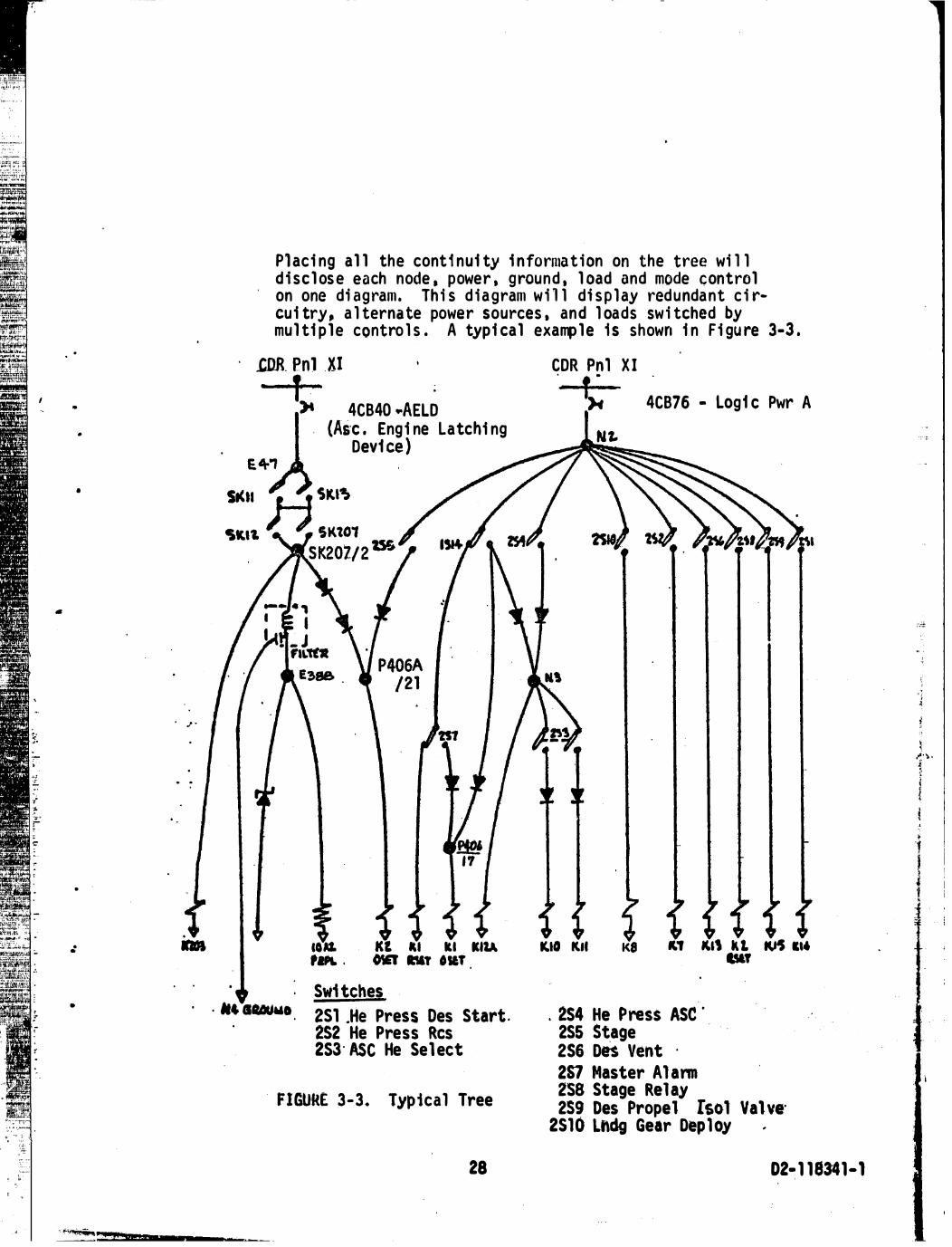
Pl aci ng al l the cont i nui ty i n forma t i on on the tree wi l l d i sc l os e each node . power , ground , l oad and mode control on one di a g ram . Th i s d i a gram w i l l di s p l ay red u nda nt c i rcui try , a l terna te powe r sources . and l oads sw i tched by mul ti p le contro l s . A typi cal examp le 1 s shown i n F i gu re 3-3 •
.cDR. Pnl .XI CDR Pnl X I
' )I 4CB40 ·AELD , . � 4CB76 • Logic Pwr A
. ... ........
(A�c . Engi ne Latchi ng Device )
IOU. Kl IU kl 111.\ raPL . OWf ftT OIIT
Swi tches
2Sl .He Press Des Start . 2S2 He Press Res 2S3· ASc He Sel ect
FIGURE 3-3. Typical Tree
28
K.tO Kll "'' "'' k I. � ,,, .,
. 2S4 He Press ASC . 2S5 Stage 256 Des Vent ·
2S7 Master Al anm 258 Stage Rel ay 259 Des Propel fsol Val ve·
2S10 Lftdg Gear Dep loy .
I
02· 1 18341-1

_, '
' 1': -·
"-· · ' •
i:�:;·
•
· '
3.4 Tree Ana lys i s
Certai n pa tterns wi ll be i mmedi ate l y evi dent from the network trees . However , knowl edge o f the fu nct� on und opera ti on of the ci rc u i t ry i s essenti a l i n the a na l ys i s of these p a tterns . Thi s may be ob ta i ned from the i n teg rated sys tem s c hemati cs and operat i ons manua l s prev i ous l y acq u i red i n the data tas k . Wi th th i s knowl edye . powe,r- to- powe r pa ths and paths pe rmi tt i ng cu rrent reve rsal can be read i l y ana lyzed to ass ure prope r ci rcui t ope ra ti on and t �1i ng . Powe r source or powe r bus i s ol ati on , i f requ i red , can be checked unde r a l l opera t i onal modes . The d i spl ay of comp l ete conti nui ty as su res that no l aten t connecti on can des troy the req u i red i s ol a t i on . Ana l y s i s of reve rse-cu rrent b ranches wi l l s how a ny u n i ntent i on a l c i rcu i ts that exi s t as a re sul t o f certa i n modes of opera t i on . ti mi ng or l ack of d i ode res tri cti on on cu rrent flow. Appl i cati on of the power- to- power and reve rse� cu rrent cl ues i s a fi rs t s tep i n the ana lys i s and i s fac i l i ta ted by the netwo rk tree topol o�.v .
After compl eti ng the analys i s of suspect paths that are evi denced by the topology of the network tree , each node shou.l d be ana lyzed sequent i al ly to assure compl ete 1 n· . .
vesti gation . I n essence thi s requires checki ng each node to assure current fl ow i n the required di recti on a s d i ctated by the operati ons i ntended . The c l ues l i sted i n the pre· vi ous section shoYl d be appl ied i n tyrn to determi ne that no s neak condi ti on exi sts . Th i s must be done for each mode of operatton of the circui try . One method of hi ghl i ghti ng the various modes of operatfon of a �1 ven network tree f s to make copi es of the ori gi nal tree and mark i n the paths that are energi zed for each mode as shown below :
ORIGINAL TREE NORMAL BACKUP EMERGENCY (Al l Conti n�i ti es ) Mode Mode Mode
FIGURE 3-4 . Mode Di agt·ams of Tree
29 02- 1 18341 · 1
·,
� •
; . ·-
,

3.5
- - -�- � - � - - - ---
A fi nal s tep 1 n the analysi s i s the i nves ti gati on of i nterrel ati onshi ps between network trees . Thi s compos i te ana lys i s requ i res thorough unders tandi ng of the functi onal asoects of the total sys tem. Typi cal i nterrel ati onshi ps are re� ay coi l · to-contac t , base-to-emi tter control of trans i s tor swi tches , ga te control of l og i c el ements . and motor swi tch contro l s . An examp le of i nterre l ated network trees i s s hown bel ow . Analys i s of each of these trees depends on operati ons 1 n another tree .
EIGURE 3-5 . Interrel ated Ne twork T rees
Sneak Ci rcui t Analysi s Reporti ng
•
Two el ements of s neak c i rcui t analys i s remai n afte r the sys
tem has been analyzed i n d�ta i t� The� are the reporti ng of s neak c i rcui ts to the res pons i b l e a uthori ties and the certi fi cati on of ana lyzed ci rcui try a s bei ng free of s neak ci rcui ts . The n�twork trees se rve as a record of ana lyzed c i rcu i try . A wri tten report accompan i ed by a s chemati c d i agram showi n g the sneak path o r prob l em s hou l d b e u s ed t o ma ke affected parti es �ware of sneak ci rcui ts and of any requ i red correcti ve acti on .
The s neak reports s houl d be generated and prope rly di spos i ti oned · as each s neak ci rcu i t i s di scove red . I t may a l so be des i rable
to concl ude each major product . mi s s i on . or sys tem wi th a sumnary report descri bi ng a l l the app l i cab l e fi ndi ngs of the sneak c i rcu i t ana lys i s effort . The ove ra l l analys i s and reporti n g may be ass i s ted for l arge . comp l ex e l ec tri cal systems through data proces s i ng as d i s cus sed i n the next sect i on .
30 02- 1 18341 · 1
,•' ' \ •

- .
•
•
•
•
•
3 . 6
3 .6. 1
Comeuter Ass i s tance i n Sneak C i rcui t Ana lys i s 4
Two computer programs h a ve been devel oped to a i d the Apol l o s neak ci rcu i t ana l ys i s tas k . These a re the Auton�ted F i l i ng Program ( AFP ) and the Au toma ted Sneak P rogram ( ASP ) . The Au tomated f i l i n g Prog ram i s an i n fo rma t i on re tri eva l sys tem wh i ch wi l l s tore , sort , and repo rt d raw i ng i ndex i nforma ti on . Th e Automa ted Sneak P rog ram i s a compl ex sys tem i nvo l v i ng a "pathfi nde r" program whj ch traces ci rcui t conti nu i t i es to de ri.ve va ri ous re ports used to a ss i st engi nee ri ng ana lys i s . These two p rograms and thei r use wi l l be d i s cus sed more fu lly i n the fol l owi ng paragraphs .
Automated Fi l i ng Program ( AFP )
The Automa ted fi l i ng Program i s used to establ i sh the schemati c basel i ne for the electri ca l a n a l ys i s by effecti v i tyconfi gurati on l i s ti ngs . Drawi ng and schemati c i�dexi ng deta i l s are i nput to AFP . A master fi l e i s then created from the d rawi ng data . Upon user reques t . the mas te r fi l e i nformati on i s s o rted . and the req u i red outp u t wi l l be pri nted . AFP wil l thereafter p rov i de reca l l capab i l i ty for other us er req ue s ts . Compl ete deta i l s are g i ven i n 02 - 1 1 8243- 1 . "Automated Fi l i ng Program Requi rements 11 •
J .6 . 1 . 1 AFP Mas terfi l e I nformati on
The fol l owi ng · i nformati on i s contai ned i n the AFP mas te rfi l e and i s avai l abl e i n vari ous formats for i ndexi ng the reference d rawi ngs to be found i n the centra l drawi ng fi l es :
a . Reference des i gnator o f the component o r s ubassemb l y
b. Part number of the component or s ubassembly c . Schemati c number
d. Schemati c ti tl e e . Vendor code ( names suppl i er )
f. Propri etary code ( denotes c l ass i fi cati on)
g • Rel eased , but uni ncorporated . Engi neeri ng Orders ( EO ' s ) or Advance Drawi ng Change Noti ces (AOCN ' s )
31 02-1 18341- 't
·�
'
1
· ; ..,. • . .PWA.¢ta: si ;s; 344,¢.: a · st¢M14jf$7 a ;ep '«..C:.#il!#i4P+"fi9AiJ44t'P,.p:¢.*::':::n):qg:;:o;:w;,;:assw:;g;;t$.¥4444!SQCS !Pt'J4Att;;:A!{ Q?ttii

h . Subsys tem codes 1 . Fi l e status ( i n fi l e or not)
j . Veh i c l e or end product effecti vi ty
k . Revi s i on l e tter
3 . 6 . 1 . 2 AFP Reports
The above i nformati on r.an be sorted and reported by the computer i n vari ous formats . The three major sort rout� nes are :
a . Reference des i gnator
b . Part number c. Schemati c number
In each cas e . a report can be provi ded for use i n ascertai ni ng fi l e and schemati c i nformati on . For examp l e , i f only the reference des i gnator of a subassembly is known . the fi rst sort and report rou ti ne gi ven above wi l l show a l l perti nent part numbers and schemati c numbers . L i kewi se . i f only a part number i s known , the part number sort and report wi l l l i s t appl i cabl e schematics and reference des i gnators . The schemati c number sort and report g i ves a l l part numbers and reference des i gnators associ ated wi th each s chemati c . Furthe�ore , these reports may be ordered by i nd iv i dual veh i cl e effecti vi t i es or by a range of �·ffecti vi t1es , wi th the excepti on of the part number report , Whi ch is avai l abl e by a1 1 effecti vi t i es only within the present
. program. Of course , i n each report the appl i cabl e revi s i sn letters and outs tandi ng Engi ne�ri ng Orders a re g i ven for each effecti v i ty .
02- 11834 t - 1
::'IE ·\ ,. ! . . '
�- ,• . .. . . ... . �-� l i �
-I

--.7 ::�. ·.-r �· 'jt ". ' , ., ...... ,.;, , .. ,.�,, ' .
' '
•
..
•
•
•
•
3 .6 . 2 Automated Sneak Program ( ASP )
The Automa ted Sneak Program 1 s des i gned to remove eng i nee ri ng analys i s dependen cy upon i n tegra ted sys tem s chemati cs . I nteg ra ted s c hema t i c s i n he rent l y contai n e rrors because they are h uman l y deri ved from the man u fac tu ri ng i n forma t i on . Hardware produc t i on i s based upon deta i l s chema ti c s and wi re l i s ts . These documents a re mo re accu ra te , comp l e te , and ti me ly than the i n tegra ted schema t i cs , wh ich a re genera l l y produced \-/hen t i me i s ava i l ab l e a nd . . fo r engi nee ri ng refe r@nce only . Even s l i g �t e rrors o r change omi s s i ons i n the i n te g ra ted schemati cs can comp l e te l y i nva l i da te engi nee ri n g ana lyses based upon tnos e schemati c s . T h e a l te rna ti ve i s u se of deta i l s chema t i cs and wi re l i s ts fo r each eng ineeri ng anal ys i s . Usu al l y , the vol ume of s uch i n forma t i on i s so g reat tha t 1 t di s cou rages use by a n eng i.nee r conce rne4 wi th ove ra l l sys tem knowl edge . Moreove r , s uch data i s not i n the format desi red by el ectri c a l sys tem ana lys ts . The Automa ted Sneak P rog ram prov i des a w�y of a l levi a t i n g the meni a l ta s k of traci ng c i rcui t con t i n u ·i ti es th rough deta i l s chehla t ·i cs and wi re l i sts . A gene ra l des cri p t i on of the p rog ram i np u ts , proces ses , and repo rts and the i r u s es i s g i ven i n fol l owi ng paragraphs . Comp l ete deta i l s o ! the program opera t i ons ·are g i ven in 02- 1 1 8081 -28 , 11 Req u i remen ts for the Automated Snea k Prog ram . � and i n 02- 1 1 821 1 - 1 , "Automated Sneak 'rogram Sys tem Documen t . 11
3 . 6 . 2 . 1 ASP I np uts
The Automated Sneak Program processes circu i t data from wi re l i st tapes and from ma·nual ly-prepared keypwnch i nputs whi ch represent conti nui ti es wi th i n equ i pment modul es and panel s . The exact data and formats are d i s cussed in 02-1 18081 -28 , as referenced above . However , any di scuss i on of the fonmats wou1d be uni que to Apol l o and i ts mu l ti -contractor envi ronment ; therefore , only the type of data processed wi l l be di scuss ed here . Appendi x A i l l ustrates Apol l o i nput codi ng techni ques •
The wi re l i sts may al ready exi s t on computer tapes , or they may be generated from whatever producti on wi ri ng records exist . The data must i denti fy wi re segments i n te�s of FROM and TO end points which are usual ly .plugs , jacks . or
� .
33 02- 1 1 834 1 - 1
. , , . . .. j ..... . · • . \

•
•
•
•
• •
•
---- --- - ---
termi na l boa rds . O f cours e , other end te rmin ati ons a re a l l owab l e . T he basic i dea is t hat the wi re l i s t w i l l p rov i de data neces sary to des c r i be circuit con tinu i ty betwe en the externa l connectors on the equ i pment modu l es .
The equi pment modul e interna l data is s uppl ied by conve rti ng the de tai l s chema ti cs i nto poi n t - to�point contin u i t i es in the fo rm o f a ma nua l l y-prepa red 11 i n terna l wi re l i st , " wh i c h i s then keypunched for compute r maste rfi l e ge ne ration . FROM and TO end te rmi nations a re used to de s c ribe ci rcuit con� ti nu i ty s egme n ts , whic h may be modi fied wi th fun ctio n a l and l oca ti on rema rk s , d i ode and impedance nota tions , pl us a vari e ty of othe r i nforma ti on . a s gi ve• t i n Append i x A of thi s document.
3 . 6 . 2 . 2 ASP Processes
The ASP sys tem provi des for updati ng the wi re l i s t mas terfi l e and the equi pment modul e conti nui ty mas te rfi l e . as requi red i n order to ensure accurate and timely c i rcui t i nformati on . · When the data masterfi l es are comp l ete ( or a t any other des i red time ) . the program wi l l merge the wi re l i s t wi th the equ i pment modul e data to provi de tota l c i rcui t cont i nui ty i n one mas terfi l e . The tota l data i s then ass i gned numeri c codes duri ng a data reducti on phase of the program and these numeri c codes are strung together wherever cont i nu i ty exi s ts . I n other words . the data i s searched for comp l ete numeri c "ci rcu i t paths 11 • Any i ncomp lete ci rcui ts ( open-ended wi res ) are a l so found and reported . After a l l the data has been searched . the resu l tant numeri c ci rcui t paths are regenerated back i nto the i nformati on carried on the wi re l i s t and equi pment modu l e mas terfi l es for ease of human i nterpretati on and ana lys i s .
3 . 6 . 2 . 3 ASP Reports
The regenerated c i rcui t paths are reported i n the ASP Path Report ( See exampl es of a l l reports 1 n 02- � 1 8081 -28 ) . Th� Path Report shows the c i rcui t conti nu i ty poi nt-by- poi nt w1 th wi re and equ i pment modu l e ident i fi cati ons . perti nent d rawi ng numbers . d i ode . i mpedance . and remarks i nformati on as ori gi na l ly i nput for each da�a segment . The nami ng conventi on of the poi nts wi l l i denti f� swi tches . c i rcui t breakers . rel ays . motors . and other such ci rcu i t components and l oads . The Path Report therefore represents c i rcu i ts i n a l i s ti ng form rather than p i ctori a l ly . and a l so provi des
34 02· 1 18341 - 1
-·
... ·· · ·• ·

•
•
•
•
•
•
- - -- �� -- �� --- �- ----- � - � - �- � -
reference i nfo• mati on wi th functi ona l remarks . Moreove r , the Path Report fonns the base l i ne for many deri ved reports to ass i s t engi nee ri ng ana lys i s .
The reports de ri ved from the paths are : Nodal Set Ma tri x , Termi na l Branch Report , Swi tch Branch Report , Load Report , Di ode Report , and Spec i a l Node Cros s - Re fe ren ce Report . These reports a re di s cussed be 1 ow , genera l ly as a pa ckage compos i ng a " Nodal Set , " whi ch compl ete ly des cri bes a network t ree .
· a . Noda l Set Mat ri x
Thi s report cons i s ts of a " connecti vi ty array " wh i ch i denti fi es the nodes i n a network tree ( re l ated paths ) and shows thei r rel ati onsh i p to one another wi thi n each path wh i ch forms the tree . Di ode , swi tch , and l oad i nformati on is a l s o contai ned . The report is used to sketch the network tree and provi des " se l ecti ve-suppress i onof-detai l " to s i mp l i fy topol ogi cal analys i s .
b. Termi na l Branch Report
Th i s report l i s ts the fi rs t and l ast branches ( segments ) of �ach path of the Nodal Set matri ces . The i nformat i on i s �sed to l abel the power sou rces and ground points on each network tree . Open end poi n ts , wh i ch show unternli natad wi res or data di sconti nu i ti es , are a l so gi ven .
c . Swi tch Branch Report
Thi s report l i s ts a l l the c i rcui t b reakers . swi tches , and umbi l i cal di sconnects i n each nodal set and references thei r respecti ve paths . Each i tem carri es i ts remarks and othf: t' i nformati on coded i nto the ori g i nal i nput data . The report i s used to compare functi ons of the swi tches wi th i n a tree and to l abel .swi tch setti ngs and functi ons on th£! tree �; ketch . I t a l so ca l l s attenti on to the fact that umb i l i cc1l di sconnects mus t be treated as swi tches ·f n sneak ci rcu i t ana lys i s because they are uncoup 1 ed duri ng the anti ci pated sys tem opera ti on .
d . Load Report
Thi s ASP report l i s ts a l l the i tems wi th i n a nodal set
35
. .
02- 1 1 8341 .. 1

that a re coded i n the ori g i na l i nput da ta a s c i rcu i t l oads ( " L " - i tem names ) . I t i s used to d raw and l abe l perti nen t l oads on the network tree s k e tch . A re»� rk wi l l i denti fy the func ti on of each I oad .
e . Di ode Repo rt
Th i s report l i s ts the d i odes and the i r respec t i ve paths wi th i n each nodal s e t . I t i s used to d raw a n d l abe l a l l d i odes on the network t ree . The i np u t rema rk s wi l l p rovi de any s pec i a l i nfo rmati on rega rd i ng each d i ode .
f . Speci a l Node C ros s- Reference Repo rt
Th i s ASP report p rov ines a functiona l c ros s - refe rence for s peci al ly-coded i tems wi th i n each noda l s e t . For examp l e , Kl may rep resent a re l ay coi l i n Nodal Set 003 . The Spec i al Node C ross- Reference Report for Nodal Set 003 wi l l then show. the · noda l set i denti fi ca ti on of c�ntac ts con t rol l ed by Kl . Mu l ti p l e re l a ti ons h i ps a re a 1 1 owed . and the c ross - reference i s g i ven fo r each s pec i a l node - - i . e . , both for the coi l and fo r the contacts i n the ir res pecti ve noda 1. sets . Of course , the c ros s - re ference techni que i s appl i ed to many_J!�es. i n add i ti on to rel ay coi l s and contacts .
3 . 6 . 2 . 4 ASP T ree- S ketch i ng Procedure
the ASP reports are used pe r the· ·fo l l owi ng p rocedu res to comp l ete l y s ke tch and l abe l the netwo rk trees :
a . Sketch the T ree
Use the Matri x , Tenmi n a l Bra nch Report , Swi tch Report , Load Re port , and Di ode Repo rt . I t i s sugge s ted that a rou gh d ra ft of the tree be made from the ma tri x , then red rawn fo r better l ayout be fo re l abe l i ng the tree . Sub- t ree c ros s connec ti ons through h i gh i mpedance may be s hown as opens wi th nota ti on of i mpedance and refe rences be tween s ub- trees when more than one page i s requ'! red .
36 02- 1 18341 - 1
I I ., �.
..... .. ,. . ,.
.., .. . .. I
, A
•
•
•
•
•
•
e A
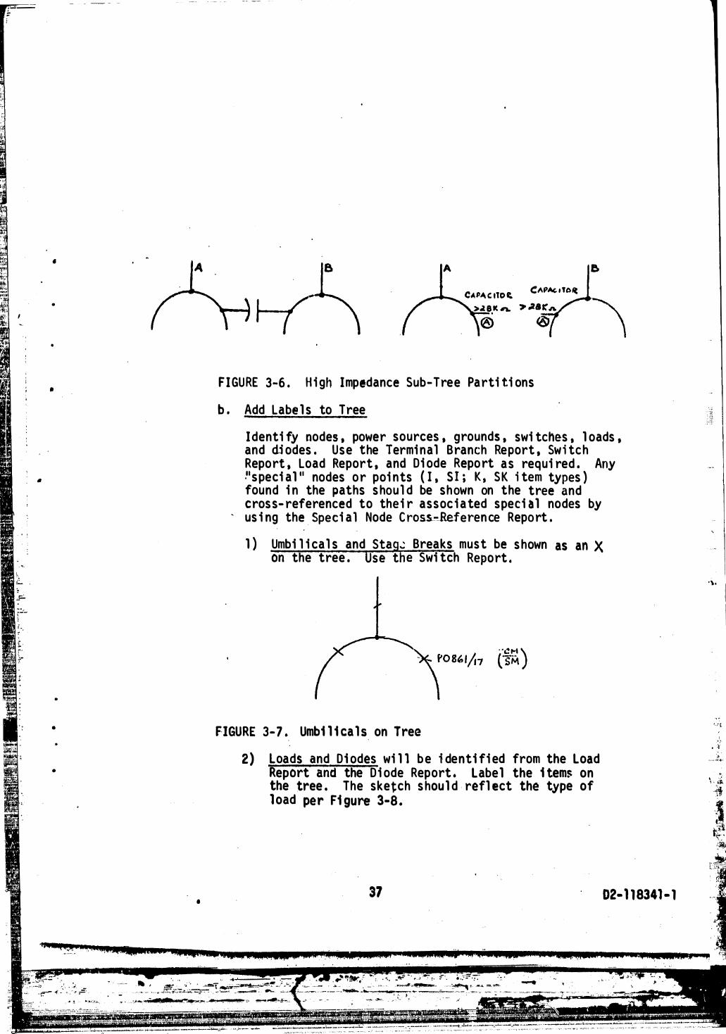
FIGURE 3-6 . H i gh Impedance Sub-Tree Parti ti ons
b . Add Labe l s to Tree
Identi fy nodes , power sources , grounds , swi tches , l oads , and dl odes . Use the Termi nal Branch Report , Swi tch Report , Load Report , and Di ode Report as requi red . Any •11 Speci al 11 nodes or poi nts ( I , S I ; K . S K i tem types ) found i n the paths s hou l d be shown on the tree and cross- referenced to the i r assoc i a ted speci a l nodes by
- us i ng the Spec i a 1 Node C ross.�.Refe ren ce Report .
1 ) Umbi l i ca l s and Stag� Breaks must be shown as an X on the tree . Use the Swi tch Report .
' '&!1"1 ) {"sM
FIGURE 3- 7 . Umbi l i ca l s on Tree
2) Loads and Di odes wi l l be i denti fi ed from the load Report and the Di ode Report . label the i tem$ on the tree . The sketch s hou l d refl ect the type of load per Fi gure 3-8 .
37 02- 1 18341- 1
114 ; IQ��ft:••. stq\44i,@lttlSZU:S WJ4U.¥lll!4 qag p ¥ t .i# $ Q#IOI t!¢.:),¥,¥0 AIIPIC424JQI#OQJI!QfiiL I tA4 Qi"W.US b# i!i i:UOQIA! i.il$0t!l l44PU#t 4 t 4,4®411111.$
'\•
I . ��

•
•
.. .
•
•
•
- - --� - --- - - - - - � �-�--= - � � ----- -
3 ) Swi tches sh ou l d have both p i ns s hown to i nd i c a te pos i ti ons . Functi ona l l abe l s mus t be s hown .
4 ) Notes shou l d be wri tten to exp l a i n the c i rcu i t func t i on and p rov i de other i nformati on to a i d ana lys i s •
5 ) T i tl es shou l d be used on each s k e tch to i denti fy the ne twork a
c . VerifD._he T � agai ns t i ntegra ted a nd deta i 1 schema ti cs where necessary . 1 ) Make any neces s a ry da ta correcti ons on the tree and
1 n the comp u te r data masterfi t E'.
2) ye l l ow- l i ne the areas ...Qf_the i nteg ratt!d s chemati c mas te� that are represented by the tree . Thi s wi l l provTOe a check on ci rcu i t coverage and di s cove r drawi ng e rrors o r data d i s c rep�nc i e s .
d . Show the Operat i onal Modes of the tree confi gurati on by copy i ng the ori g in a l t ree and drawi ng the swi tches i n the i r p rope r pos i tion for each functi on on a separa te copy . T i t l e each copy to defi ne the ope rati ona l functi on . DO NOT ATTEM�T TO SHOW ALL SWI TCH PERMUTAT I ONS OF THE TRE E . An extra copy o f the ori g i nal tree s hou l d be made for future use and fi l i ng .
After the tree i s comp l ete ly drawn and l abe l l ed , analys i s for s neak ci rcui ts proceeds as d i scussed earl i er i n Secti on 3 . 4 of thi s document •
•
3 . 6. 2 . 5 Addi t iona l ASP Capabi l i ties
The Automated Sneak Program i n i ts present state ass i s ts sneak c i rcui t ana lys i s . It a l so s e rves as a data source and base l i ne for vari ous spec i a l tasks . In addi ti on , i t can provi de a foundati on for many deve l opments i n the fi e l d of compute r app l i cati ons to engi neeri ng endeavors . Some of these areas a�e di scussed i n . the fol lowi ng paragraphs •
The data mesterfi l es of the Automated Sneak Program are useful data for sorts to determi ne and l i st such th i ngs
38
f f · : ' " • • •
�- ·- ---�.:·��_;���·�,��·:,_:, . ..__... .. �-� :� ;;:.;.::.-. •, �;::::. . - �-�� ,:��"'- -- �
� -·�••-t''�;lll�y'·'"- �4 IF ""·: .· · ·:-· .-:-- -:: - .. . . -- ,.. - ,...
02·1 18341-t
--
,.� . .... . • J . '

HEATER
RELAY CONTACTS
X 0 c R
1 T
RESI STO R CAPACITO R INDUCTOR ; "CHOKE11
T RANS FO RM ER
DC
DC
RELA'l.- ------- -. .T RANSISTO R T RANS ISTOR D C-TO-DC COI L AMPL I F I ER SW ITCH _ _ - - -- - - · CONVERTER
TRANSDUCER LAMP MOTO R SWIT CH
MOTOR . IRON·CORE SOLENOI D ;
MULTIVIBRATOR
D
POWER DIGITAL-ANALOG GATE SUPPLY CONVERTER POWER
11 BARBER POLE" ; VALVE
GATE INPUT
FIGURE 3-8 . Lo4d Symbol s for Tree Sketche�
39 02- 1 18341 - 1
-. ,. �.l J ... . . .. .
'·
• •

� · !---:
,, .. .
' '
til
..
•
•
•
•
4ACCUW iAV4tll
as al l c i rcu i t b reakers wi th the i r ra ti ngs , functi ons , l ocati ons , and appl i cab l e s c hema ti cs . Such a sort can eas i ly be p roduced for swi tches , umb i l i ca 1 s , 1 oads of va ri ous types , d i odes . moni tor poi nts , etc . The l i s t i ng can a l s o i nc l ude a re fe rence to the perti nen t network tree by n�da l set number •
Engi neeri ng a na lyses othe r than s nea k c i rcu i ts can use the network t ree s ke tches produced through 1\SP . Batte ry a nd bus l oadi ng s tud i es . Fa i l ure Mode E ffe c ts Anal ysi s , \'l i re s i z i ng s tudi es , anoma ly and change a n a l ys i s , and othe r e nginee ri ng tas kS- can use the trees to ga i n qui ck sys tem knowl edge , then suppl ement the tree� wi th the path s and othe r reports f.or acces 3 to s pec i fi c deta il s and- l oca ti on of appl i cab l e schematics . I ndexes a re p roduced to enab l e s peedy l ocati on o f any c i rcui t i tem i n i ts ASP tree , and from the re, re l a ted i n forma t i on may be ob ta i ned through ASP data .
An area that shou l d be pursued w i thi n ASP i s that of Drov i d -
1 ng " c hange package" capab i li ty wile re i n o o l y d i ffe rences a re reported wi thi n trees produced by s ucces s i ve ASP ru ns . ( I n fac t . s u ch a p rogram req u i rement speci fi c a t i on has been p r� pared i n Hous ton : i n ter-depa rtment coord i na t i on sheet 5 - 2933-HOU-065-01 4 , 11 Noda l Set Compa r i s on. P rogram" ) . Even be tte r woul d b e a capabi l i ty to run th e program to p roces s only changed d a ta a nd r�port accord i ngly . (A "cru tch'• me thod of perfo rmi ng tha t functi on i s now ava i l ab l e through s e l ecti ve c i rcu i t sea rches , but th i s p resupposes tha t the changed areas are known . ) Wi th i n presen t s tate-of- the-art i s the capab i l i ty te use data produced by ASP to gene rate network trees d rawn on m i crofi l m/ CRT p l otte rs by a computer . Such trees can e l i-mi nate the manua l s ke tch i ng tas k now requ i red to u ti l i ze ASP output . The computer-produced trees can be expanded to vari ous l evel s of deta i l and rep l ace or supp l ement exi s ti ng i ntegrated schema t i cs . The same tech n i que cou l d l ead to a utomated deta i l s chemati cs . wi th eng i neeri ng i nfo rmati on rel eased enti re ly th rough data p roce s s i ng .
Perhaps the ul ti mate machi ne u t i l i zati on i n engi nee ri ng tas ks wi l l come wi th i nteract i ve graph i cs whe reby an on- l i ne CRT termi na l i s used to di spl aj the trees a t a conti nuous ly
40 02· 1 18341· 1
., 7 � 1.
t
I ' .
....
·+ <

•
..
. .
•
vari ab l e se l ecti ve l evel of deta i l to supply the g reat� s t ass i s tance i n network ana l ys 1 s . Such a te rmi na l cou l d a l s � be used for rea l - ti me change i nput , aualys i s . approval . e ru1 rel ease . It wou l d provi de i nstantaneous data a va i l a b i l i ty and correcti on capabil i ty , and feedback channel s cou l d b e i nc luded from a l l use rs i n the p roduct i on envi ronmen t . A system of such termi na l s cou l d then e vo l ve i nto a re p l a c e ment for ex i s ti ng techn i ques of engi neeri ng con�1un1 cati on on paper through dr.awin.gs . The CRT di s p l ay termi na l sys tem wou l d offer i nherent advantages 1 n data avai l ab i l i ty . qu i c � t! r reacti on ti me for changes , and space/we i ght savi ngs over the exi sti ng drawi ng systems of commun i cati on •
41 02- 1 1834 1 - 1
. '
=-'":. �· .�,..- ::·-· �� .�·�. =�� .:.�-�����;;.;;r�· ·�. ". - . � -� ---������ ... lOO!' ........
' l .,

3 . 1
•
•
..
•
Summary and Conc l usions
Figure 3-9 shows the steps involved in performi ng a s n e "•· c i rcu it analysi s . The flow d i agram i� general i zed , and tt� conversion of data to continuit ·i es , etc . • i s neces sa ry L .. · r t ' �· purely manual or the computer-as s i stooapproach . The d i f f c r t· ' · l "'� arise in formats , techn i ques . and orderliness of record kcep \ � q . The automa ted method offers other advantages over the ma nu" l approach . These are :
·
a . Removes dependency upon "deri ved " system schemati cs . which may not. be.- �'as bu i 1 t"
b . Prov i des d i fferent pE rs pecti ve . forc i ng analyst to see circuitry different from desi gner ' s viewpo i nt
c . Traces detail conti nu ity faster than manual . wi thou t t i r i ng or overlappi ng areas
d . Forms general data base . for other engineeri ng uses
e . Offers development capabilities for new applicati ons and _proce ,;es
Di sadvantages of automation are :
a . Data 2LOcessing equipment requirements
b . L1earning curve for techniques and operat i ng knowledge of program operations
c . Batch processes at present , rather than qu i c� . selective response offered by on-line systems
Sneak circuit analysis has been found to be expensi ve , but worthwhile . One sneak occurrence can cost more than the entire analysis . Ideally , the analysi s should be performed as soon as complete design detai ls are known . and it should be conducted by a team independent from the desi gn organi zati on to avoid prejudi ce in system reliabi l ity . In any event . the analysis must be performed by personnel with total system overvi ew capability, for i t i s the subsystem or assembly i nterconnecti ons whi ch most frequently give rise to sneak probabi lities. Each component and assembl y is usually adequately des i gned and tested to do its job i n a fixed environment , but as the tot a 1 sys tern size and comp 1 ex 1 ty gro\'!S . so does the capabi l ity of the antici pated env ironment to change unexpectedly .
42 02- 1 1 8341 - 1
I .' .. . .. . .. .

•
•
•
•
•
•
•
•
· · �· 1¥QI UQ; ... .
Sneak c i rc u i t ana ly5 i s offe rs an approta ch to mo re con1pl etc l y dete nni ne a l l pos s i bl e sys tem modes , both the expe c ted and the une xpected . T here fo re , s neak ci rcu i t a na l ysi s c an he l p reduce sys tem cos ts by prevent ing unexpected equ i pmen t damage duri ng tes t p l us subsequent rede s i gn .and retes t . Moreove r , s neak c i rcui t ana lys i s can 1 1e l p a ch i eve a more 11 fa i l sa fe " produc t through comp l e te eva l uati on of a 1 1 systen1 responses \·lhic:h may be brough t abou t by p rocedu ra l d i s cre panc i e s . f i n a l l y , through the va ri ous l eve l s o f overvi e\'1 provided by the se l ecti ve- l oss-of-deta i l approach i n sneak c i rcu i t analys i s coupl ed w i th a u toma ted d i s p lay dev i ces , new dimens i ons i n engi neer ing capab i l i ty may a r i se to sue .. cessfu l ly des i gn and i n tegrate ever l a rge r compl ex sys tems •
43 02- 1 18341 - 1
,#" .•• •
l i '·

r: . . -.. t i=-
� .. . . � '
� �
.
·•·
' ,. ( ' ,.
•
•
•
•
. .
•
•
OBTAI N DATA • SCHENAT J CS • MANUALS
� CON VERT CABLE SCHH1A T I CS TO CONT I NU I TY
� CONVE RT BOX SCHE�1AT I CS TO CONT I NU I TY
l ADD DEV I CES t SWI TCHES . . • DI ODES • TR ANS I STORS • LOADS
DETE �I NE NODE S AND TERtUNAT I OtiS
P0\4ER & GROUNDS W NETW RK.
TREES
.__ __ -( DETERt·1i NE PATTERftS]
l·· �s
FIGURE 3-9 . Sneak Ci rcu i t Analys i s W�rk Fl ow Di agram
44 02- 1 18341 - 1
�-------·-· ---� ,._.,.,..._ •. -_. _.,__;' F 44A_QI ;t¥£ . . 4 �-� �·- · ··{£#!£U.i--LLS .. I# 4� ?Ji'=!�?!- . \. ' tP1.'!'*?. ' . . 9t;t;#;zwe UCP 4 * . .' S _ -j . $_! t 4 lb?C ,f j?4 ·£-Qac l ZA t Pc.lj
.�· . .. '
I i •
f.
j

•
•
•
•
•
•
02- 1 1 834 1 ... 1
APPEND I X A
APOLLO B I D I NPUT GU I DEL I NES
Thi s append i x i l l us tra tes bas i c gui de l i nes fo r the Apo l l o Au tomated Sneak Program "bl ack box " i nte rna l da ta ( B I D ) cod i ng . A . l Card T�pe and Forma t
There are two types of B ID i nput . The B l i np u t prov i des genera l i nforma ti on a bou t a part i cu l a r "b l ack box " . whereas each B2 i npu t desc t� i bes a conti nu1 ty s egment w1 th i n the box , equ i pment modu l e • or panel .
a )
b)
Bl I npu t Format , Fi gure A - 1
Every B l i npu t wi l l be compos ed o f fi e l ds con ta i n i ng the fol l owi ng i nformati on : Control F i e l d 1 ) 8 1 . i denti fi cati on code , col . 1 -2 2 ) acti on code . co l . 3 3 ) refe rence des i gnator or mode l numbe r , col . 4- 1 8
Non-Contro1 · Data 4 � contractor code . col . 1 9 5 area code , co l . 20 6 bay numbe r , col . 2 1 -23 7 ) drawi ng number , co l . 24-41 8) part number , col . 42-6 1 9 ) box ti tl e , col . 62-80
The contr·ol fi el d i s that porti on of the data necessary for the record to be uni que and i s genera l l y used i n sorti ng . The i nformation outs i de the control fi e l d of a record i s cons i dered reference data .
After a Bl record for a parti cular bl ack box i s on fi l e , i t wi l l be pos s i bl e to des cr i be the i nterna l wi ri ng of the box wi th 82 i nputs .
82 Forma t , Fi gure A-1
The second type of BID i npu t . 82 . des cri bes the i nterna l wi ri ng of the b l ack box . Every 82 i npu t wi l l be compos ed of fi e l ds con tai ni ng the fol l owi ng i nformat i on :
-45-
· "" �; «;pecu '*'' 41441!* .:e: ; : ac uaa ;;a:$2 rt a ,a ;; a: u: up :. :, ;:a as¢ a ¥ :ea:e ¥ A eaa.:::: P 4::CC414Z ''*'*;; .,, Atot:
·-
11' ' \tr. o ·' J

�:," . . � .; 0
l
J �! J - .•. . : J t
! l
, _ . ; il l : I �· ..
j . �If ; ; 1 r i �: I . l , . ' I · · , . 1 , · I I . , , '·
· i · I � 1 ' 1 .
� , . ' • ' i .• ' ·· l ' , : II •· I ' it I 2 • f.· t ·.
" '
. J . . ,f� .. :l !• i : ' i � .
d ' . ; ' 1, 1, H , • :r ' 1 . • ' I i · .� ·n ·L
.... ;,
'
r· f · [ -\ ' -r : ,·· : 1 ' , �t• I "
; , ; l ' ·· r�W
'
'�
" : '
.
• .
:�. �:
':
" " . .l. t ' · ,. i ..
- .i f ;', . · . · • ., , , ,
,; ' .. � fl, ';l ·, :/: t= · . :tr . ' , . · �. !. . . I I'· , - r rJ . . ·i �: '
: 11 : il· ' 'il .. J --�
"'
.,. �
• • t . . '
, ._ • •
801 ltnt� I!AT� IIPUf F4IM .
� T .,.,. e ,. &AY II " A Rlfltt£Ht!£ ti lt lilt:. DltANIN. NIIMeiR . , T E .. ' e • �&SJGNATIIR
• .p. A It• .
811 A CI I I� •-•AI I I21 t I I I l J l N c. I i vt3l� t- J, tst t lo l3 1zl �Br 1 1
8:2
� l [ '
Cl t llfi-IAI I I2l I I I I I I l
r - · -- ------- - - - -- --- -- - -_ _ _ _ _ _,__,__ - -
--� ---
- -··
---- - · · ------ -j t '
,_ --· ·
.... - - --i - -
· - · -- - - -
•
FRrJM Pill .lT£M � I! I
P o 2Jotta otoJoJL SIF I "·I oto lol2
I r - 1 4 I I I I 'tl J rs11 s1 J ofo�� J ro· r �ru
!LIII / 131 . I l I I lll_�IL I I I 1 1 r f I I l I W I I .L �Lu�·
IKI2 Sf _I I J; l.t J5Z)Il) LU I ! 1 1·-r I ITl J I I l I I I I I I 1 1 ITT IT rl I I
1 1 I 1 1 1 �-=· -. _ ._ _ _ _ . TTI-TT I ' .
T/JJ !TEM Pill It, 1M
SlFI I I'L I ofolofi I I I Itt .I J • • I
Slllll J J nlol ol3 - _l T lil l l l fil l
llfliQ[Jl r J l GINil>l I I I I I IP IWIRI f I I I I IKIZ.ISI I I p� '1�.1@1 £ �Iu_ IGINll>l I I Jl r -lliTT- -1 I I
J I I I I 1, I I ll l lJ I I I I I I I J I I I I I I I I I I 1
n ' (I D !" -
,_
----
UNIT PART NUMB£R Bl)( TITL£ 1-u u r lv 3 ;'-i-17iB,! l01.3lZi-!2JOlll J J J I ] nu!SIE:t jBJ�jX1 lAJSISlYt i 1 I Ji 1
1."1fr'T • Kn f
I I-I
R£MARKS ••
cu�l ! l,t iJJ r .cunTirrJIDlJ1TI-rr t 1 ; . I 1 ' l � � Sl IAI�IPI IAUIS1�1 L t t 1 1 .1 1 l l i l l t l l l l lJ J l l f l I J I
! ! '
-r- � 1 1 • 1 r 1 r i 1 ' ' rTriiiiTIJ1 r 1 1 IT 11 , , 1 , , J , J I
: .r 0)0 1
ti . - I =r 1-
� �&?�Ef iSl�ifiJC1ID i IL.O lll. [ [TJ mJD�L1-l.t l l.llO�Ill�ILL Lil.J rri lTD_ I r rr1 IJll]l
h1Hii!l!!r1Lizi�IH ITJ,]i]iOJZJCIAIDiiilil III! 131 Ill k:.liilJGf� gi;J tti2J$I &iD!cl,! la[iJSll&"fll 11 I fTUi liiLLTJ.ITI - l '
l I l- 1 : I I I _ i , i � f I ; l l I I I l � - , t I I i J I . lJTIJ j 1 J"J II.TITII_t[lTI I I l U_LUlliii.IILUJ _i J 1 1 l . l
al.g l :Pffi�lble:l!>i WrJa\tth.J,U�1NIG!l,.Lt.Jf�l J�� JS17JR1J.l.CJJ'J K;:fm l l "' ·T -
r TT ll�IIJIW _L[ll_O_D�DJIITITITO:TIJ. �Ll._L . I . J I I [ · 1 I I I I ·l l L [ llU l ·J 1 1 1 il] _ L I 1 1 1 . 1 1 1 1 J J 1 .L _ . I I J I I I I _L I . j .U ...L I i i . t�L · 'I I I I I i 1 1 l 1 l � t I I I i ·I
I -, I I I Ll I I J I I I '1 t f I l ! rl T l l i I .LI I ., a t J J LLJ_L T I I I I I I f I J ; � J :1 I I I I I I I 1 � 1 I l 1I1TI-rn I l ·r : I I I fT liJ I I I I · � ·-• l r1 1 11. nn 1 � ,.
FIGURE A-1 . Bid Input Sheet wi th Typical 81 and 82 Entries
·� · .... - ,..... • ..-....--- �·.'$· · � �--- ; ;:t i i�:i . . . . . . . .. . . . -
'0 N l ---·
� w ..:::.. ' --

•
"
II '
. ..
•
:, . l
-� � - ---
Con ti nued
.Contro l Fi e ld
3 refe rence desi gnator or model number . col . 4- l f:
1 ! 82 i denti fi cati on code . col . 1 -2 2 acti 1n code , col . 3
4 From des i gna ti on composed of From i tem co l . 1 9 .. t t� and From pi n . co l . 25-28
•
5 ) To des i gnati on composed of To i tem , co l . 29-34 , and To p i n , col . 35-38
Non-Contro l Data 6 ) d i ode , col . 39 7 ) i mpedance , co l . 40-42 8 ) remarks , co ·l . 43-80
, ..
A . 2 Acti on Codes
The computer wi l l perform one of three pos s i bl e action� wi th each i nput . The a l l owed acti on codes are "A" , 110 11 and "R" . An "A 11 code instructs the computer to add the i nput to the data fi l e . A 110 " code i ns tructs the computer to del ete data from the fi l e , and an " R 11 code i ns tructs the computer to revi se i nformati on beyond
. the control fi e l d of the record , whi ch mus t already be on fi l e .
A del ete acti on code on a Bl i nput card wi l l cause a l l records on fi l e for the box to be de l eted -- the Bl p l us a l l the re l ated B2 records wi l l be removed from the computer mas terfi l e . However , a de l ete acti on code on a 82 i nput card wi l l cause only the correspondi ng 82 record i n the computer mas terfi l e to be del eted . Thus , i f an enti re box needs reworked , a B ID card can be submi tted to remove a l l the o l d data , and a new set of BlA and B2A cards may be i nc l uded i n the same run to re-establ i sh the box i n the des i red confi gurati on on the computer mas terfi l e . When only a few segments need reworked , the 1 ndi vi dua 1 820 and B2A i nputs nray be used wi thout di s turbi ng the remai nder of the box records .
When i t i s not necessary to e l i mi nate a conti nui ty segment s peci fi ed by a g i ven From-To pai r but i t i s des i red to change the d i ode pol ari ty , i mpedance va l ue , or remarks for the s egment , then the revi se acti �n code (R ) shou l d be used . Wi th "R" i n col umn 3 . the computer wi l l repl ace the appl i cabl e fi e l d wi th the new data entered on tne card . A compl ete control fi el d i s requi red to i dent i fy the appropri ate masterfi l e record , of cours e . Thus , i f the mas terfi l e' has a record
(OLD �\STERF ILE RECORD ) 82 C1 5-4A404 P0215 0003 J001 7 OOAl + 001 PWR TO J-BOX
I
-47-
--,. .
'i

A . 2 Conti nued
02- 1 1 834 1 .. 1
- - � - -� - -. � ----;---:- �-. ---;
and an update card as fo l l ows i s submi tted ,
(UPDATE CARD ) B2R C l 5-4A404 P02 1 5 0003 J001 7 OOA l 999
then the rev i sed masterfi � e record wi l l be
( NEW HASTERF I L E RECORD ) 82 C 1 5-4A404 P02 1 5 9003 J00 1 7 OOA l + ggg PWR TO J - BOX
Noti ce that the d i ode pol ari ty (+ ) and the remarks ( PWR TO J - AOX ) were not changed i n the above examp l e becaus e the update card i nd i cated no revi s i on to those fi e lds . Another examp l e w1 1 1 further i l l us trate how the.- rev i s i on code works : OLD MASTERF I LE RECORD :
B2- C 1 5-4A404 P021 5 0003 J001 7 OOAl + 999 PWR TO J-BOX
UPDATE CARD :
82 C1 5-4A404 P021 5 0003 J00 1 7 OOAl @ GND _
NEW MASTERF I LE RECORD :
82 Cl 5-4A404 P021 5 0003 J001 7 OOAl 999 GND
In the above update , the commerci al 11 at 11 ( @ ) was used to revi s e a fi el d to b lank . · I n. fact , the commercial 11at 11 i n the fi rs t col umn of a non-control fi e ld on a revi se update card wi l l cause that enti re fi el d to be rep l aced wi th bl anks , regard l ess of wha tever e l se may be s hown i n the fi eld on the update card . The exampl e a l-so i l l ustrated a remarks._ fi e:l d revi s i on . S i nce updati ng i s done by f1 �l ds on revi s i ons , whatever i s s hown on the upda te card (except b lan ks � of course ) wi l l ent i rely repl ace the correspond i ng fi e ld on the masterfi l e .
A fi nal note on re�1 s 1 ons -- the "R 11 acti on code wi l l not affect data wi thi n the control fi el d . The control fi e ld i s used on the update card so that the computer can match the data on the mas terfi l e tapes . thus i denti fyi ng the record to be changed i n the masterfi l e . Therefore an update card cons i s ti ng sf--
B2R C l 5-4A404 P021 5 0003 J001 7 OOAl
woul d cause no change on the mas terfi l e . The computer wou l d fi nd the corres ponci 1 ng o l d mas terfi l e record , then wri te i t out aga i n on the new mas terfi l e tape wi th no change . s i nce no revi s ions were i ndi cated 1 n the non-control fi e l d areas . A l so , keep in mi nd that
-48-
=-·�¥r��·'=·*2s� -=· =-i:•.ma.c· v��� --�·------------*·��------�------------�--------------�-
. . ·· ' � . . ,.

.. ...
'I
·
..
• '
'
•
•
:· l' J
..
• ..
•
A . 2
A . 3
A . 4
02 ... 1 1 834 1 - 1
Cont i nued the revi s i on code works the s ame way , by fi e l ds , on Bl i nputs . The only d i fference i s tha t the Bl cont rol fi e l d i s shorte r than
· that of a B2 , and the non - contro l 1 i e l ds conta i n d i fferent dd ta . Agai n , eve ry B I D i nput card mu st conta i n a catd type ( Bl or B2 ) , a n act i on code (A , D , or R ) , a nd a box reference des i gna tor ( to i denti fy the box name ) ,
Contractor and Area Codes (8 1 On ly ) -- - __ g
Contr-actor and area codes a re requi red on every B lA card . However , because thev are not i n the con t rol fi el d the codes are not re
. qu1 r.ed on Bl R or Bl D i nputs . The contractor code i denti fi es the hardware pri me contractor . The . codes i n use for Apol l o a re :
N - North Ameri can Rockwe l l
G - Grumman Ai rcraft Corporation
A - AC El ectronj cs Di vi s i on
Area codes s peci fy the general l ocati on of the equi pment i n the spacecraft . The Apol l o codes i n use are :
' A - Spacecraft/Launch Vehi cle Adapter C - Command Modu l e E - Launch · Escape tower G - Ground Su pport Equi pment L • Lunar Modu l e S - Servi ce Modul e
From and To Termi nat ions , .
The Automated Sneak Program detenmi nes · pa ths of e lectri ca l conti nui ty by connect) ng ci rcui t s egments through common end poi nts . 82 i nputs defi ne ci rcui t segments wi th i n a b l ack box i n terms of conti nui ty 11 From" one poi nt "To " another . When the conti nui ty segments of a box reach the external i nterfaces , the pa th i s conti nued through data s uppl i ed by the wi re l i sts , whi ch are a l so i n tenms of From and To des i gnati ons . Therefore , parti cu l arly at the externa l i nterface connecti ons of each box . codi ng convent i ons are requi red to enabl e ci rcu i ts to be fol l owed from the boxes i nto the wi re harnes�es . Other cod i ng conventi ons have been es tabl i shed to provi de for summary report producti on and s pec i a l proces s i ng . These codi ng conventi ons are d i s cussed i n the fol l owi ng paragraph s .
: � . -49-
I . ... ... .. . . . ; . .... . ...,...aaq -qu; aq so &¢ QIIAD4DfA : z-aAA r=•••
•..
- · -
1
-t ... I

02- 1 1 8341 .. 1
A . 4 . 1 Egu ipment Connectors
Pl ugs and · j acks are genera l l y u s ed to conne ct b l ack bo��!S to the wi re ha rnes ses . Therefore . the path tra c i ng program w 1 · � 1 pas s from a box connector i n the B ID ma s terfi l e to a wire 1 · � � t connector of the same name so 1 ong as the con tractor and al"ea co�Ht�s match . For th i s reason i t i s requ i red that the B I D con t i nui ty , pgments
� be coded to the ex terna l ha rnes s connector rather th a n : o the uni t connector wh 1 ch i s a part of the box . L i kewi s c , � : n e harnes s connec tor mu s t be i denti fi ed i n the B I D exa c t ly as i t �1u pears i n
• the wi re l i s t • •
•
•
•
P l ugs and j a cks i n the wi re l i s t wi l l be defi ned wi th 1 1 1 P 11 or 11J 11 chara cter i n the fi rst co 1 umn i mmedi ate l y fo 1 1 owed by f ·nur numer i cs and pos s i b l y another a l phabeti c character . A l s o , p i n · ! l�!s i gnati ons a l ways cons i s t of four charac ters ri ght-j u s t i fi ed wi th ead i ng zeros . W.ith th i s i n mi nd , i f an equ i pme nt deta i l s chem :r t i c s hows an externa l connect i o� to harnes s connector P2 1 p 1 n J , :hen the appropri ate B I D i nput wou l d i dent i fy the connecti on as uo021 pi n OOOJ , a nd th i s wou l d agree wi th the wi re l i s t d a ta . Ll other words . P21 p i n J i s not eq ual to P002 1 p i n OOOJ i n the compu t� ·� . Stri ct adherence to thi s conven t i on i s requ i red wherever the .; :D mu s t · ma te wi th the wi.re l i s t t�ro�gh p l ugs and j acks .
There are i ns tances tn wh i ch the B I D mus t be mated wi t�· the wi re l i st through i tems other than p l ugs and j a cks . To a l l ·:M fo r such cases , the computer program wi 1 1 mate box data wi th w i .... � l i s t data for a l l i denti ca l i tems (wi th matchi ng contractor and a �ea codes ) except the fo l l owi ng :
where
a . SXXXXX - - swi tch des i g nati o ns b . EXXXXX -- . spl i ce des i gnati ons c . NXXXXX -- node or poi nt names d . TBXXXX -- termi nal boards e . CBXXXX -- ci rcui t breakers f . [ speci a l character ] XXXXX - - - arbi trari ly created
refere nce poi n ts
X = any character
and s peci a l characters are : % . ) , * , ( , + , - , . , / , @ , $ . = , numeri cs , and , (comma ) •
Items named wi th any of the above l i s t of excepti or.t rema i n unique wi thi n each box and separate from any s imi l ar i tem i n the wi re l i st . Thus , there can be an SOOOl i n bc,x C 1 4Al • an SOOOl i n box C 1 5-4A404 , and a n SOOOl i n the wi re l i s t ; and each w1 1 1 rema i n separate from the others duri ng the path trace . I n other words , ea ch of the above wi l l be recogni zed a s a unique poi nt by the computer , whereas a po� �t coded C 1 4A 16 i n the BID
- 50-
.. ... I i l j ' I 1·-· · -
.... . .... .
' 1

•
A . 4 . 1 Conti nued
02- 1 1&34 1 - 1
wi l l be taken to be i dent i ca l to a poi nt named C 1 4A1 6 i n the wi re l i s t . Of course , pi n data is a l so matched for every i tem before uni queness or equ i va l ence i s determi ned .
A . 4 . 2 Spl i ces and .. Nod�
Interna l sp l i ces and arbi trari ly-named nodes wi l l be coded wi th • uE " on ly i f the deta i l s chemati c ha s i denti fi ed poi nts....-o.n the
drawi ng wi th s uch names . The "N" code i s common ly used when as s i gni ng a name to an otherwi se un l abel l ed j uncti on of ll nes i n the drawi ng . The use of a rb i tra ry " ftl and " N 11 codes s hou l d be mi n imi zed for . ease of s ubsequent reference from computer paths to
• i n teg r·ated s c hema t i cs . where i n the " E " and " N " i tems wi l l not be found . Fr'equently an un l abel l ed j unction of l i nes on a drawi ng can be named as one of the i tems to wh i ch i t connects -- i . e . , the l ength of a l i ne wi thou t i mpedance . etc . • can be s hortened to zero .
•·
•
A . 4 . 3 Termi na l Boards--and Ci rcui t Breakers
I n ternal termi na l . board connect i on s s hou l d be coded i n the B ID exJctly as s hown on the detai t .. schema ti cs . I t wi l l , however , be necessary to create From-To..-conti nui t i es for the bus sed pi il connecti ons .. Otherwi s.e , each i nterna 1 termi na 1 boar-d- pi n wi 1 1 remai n i so l ated from a l l other pi ns of the termi nal board.
C i rcu i t breakers · \o.Ji th i n a panel should be named as g i ven on the detai l s chemati c , so l ong as the "CB" codes are entered i n the fi rst two col umns of the i tem fi e l� . I t wi l l be necessary to enter each p i n of the breake.r , a l ong wi th the1 r connected 1 tems . and .... then to create a s egment between the pi ns . Thus , to camp 1 ete ly s peci fy conti nu i ty through a ci rcu i t breaker , the · From-To segu•ents woul d be :
From
Poi nt . . X CB5-0002 CBS-0002
A .4 . 4 Swi tches and Fuses
To -
CBS-0001 C BS-0001 Poi nt Y
·,
The computer wi l l treat as a swi tch any seg�ent wi th i dent i cal From and To i tems (and d i fferent pi ns ) thot begi n wi th the l etter 11511 • Thus , many types of swi tches can be speci fi ed by us i ng " 5 11 plus other conventi ons for the rema i nder of the i tem name . For
•5 1 ·

�--
-�· ..
'
.-'
; f L
I
•
•
•
•
•
...
•
4 • ' • . J �·· ·� • #
A.4 . 4 Conti nued examp l e , S- numeri c i s genera l ly accep ted as a ma nual swi tch i n the Apol l o data bas e , whereas SQ- numer i c denotes a tra ns i s tor
· swi tch . L i kewi se , " S K,. ( fo l l owed by n umer i cs ) i s u s ed fot" re l ay contacts , " SLV 11 for va l ves . 11 SCR " for s i l i con - contro l l ed rec ti f i ers . 1 15M" for motor S\'li tches . a nd so forth .
As was the ca se for c i rcu i t brea kers , conti nui ty s egmen ts mu s t be supp l i ed between the p i ns of a swi tch . Thu s , fo r a s imp l e s i ng l e
po 1 e , s 1 ng 1 e- throw swi tch the conti nui ty �10u 1 d be :
From --Poi nt A S l -0002 5 1 -0002
To -Sl - 0001 5 1 -000 1 Poi nt B
For s l i g h t ly more comp l ex swi tch . s uc h -a s the shorting swi tch i l l ustrated i n F i gure A-2 . the co nti nu i ty wou lA be :
From To -Poi nt C 52-0001 52-0002 52-0001 52-0002 Point D 52-0001 52-0003 Potnt E 52-0003 52-000 1 52-0004 Poi nt F 52·0004 52-0002 52-0003 52-0003 52-0004
where the ·r as t two s egments denote the s horti ng feature of the swi tch .
- . . . - - , ___ _ 1
52
"
D 2
- -· ---· -·- · - •
3 . . . . . .. _E •
f' 0 4 - · - · --· ·• . .
- --·-· --
- - - • ·· · · -·
F i gure A-2 . I l l ustrati on of Shorti ng Swi tch
-52-
_ g #£££ A '!t!! _ _ !f4JC#H . . !4i!12f=-'..:__-_fiild&£11 1 2 _ 2-21�-----------iiiiic iiiiiii-- ...-·-;..-· --..·---
.•

•
f
•
. .
•
... '
•
02- 1 1 834 1 - 1
A . 4 . 4 Con t i nued
Mu l t i pl e-po l e , mu l ti - throw ganged swi tches , as i l l us trated i n Fi gure A-3 , can be coded to denote each throw :
From -
Poi n t G S3-02Tl S3-02Tl S3-000 1 Po i n t J Poi nt H S3-05T l S3-05t.l 53-0004 Poi nt L
To -
53-000 1 S3 -0001 Poi nt I S 3-03T2 S3-03T � s3 .. ooo4 53 -0004 Poi nt K S3-06T2 S3-06T2
I � ·-· - - - ·
J . · - · ·-.. . .. - - -
' K
- - . - - �----� 5 . • - - -
�-- - - - - - - · ----1 - - -S3
Fi gure A-3 . Doub l e - Pol e . Doubl e-Throw Ganged Swi tch
In the above cod i ng the " throws " are arbi trari ly numbered as 1 and 2 . The l etter "Tf• i n the pi n fi e l d denotes the throw number (pos i ti on ) , and the fi rs t two d i g i ts of the pi n fi el d are used to s pec i fy the actual pi n number . Such codi ng wi l l a l l ow recogni ti on of the nature of the swi tch i n th0 computer reports and wi l l faci l i ta te subsequent analys i s of the network trees wi th respect to swi tch i ng modes .
Fuses wi � l a l s o be coded as swi tches because they may "ope n " a ci rcui t , and the tree mus t be ana lyzed for such a s i tua ti on . Therefo re , the code " SF " ·: s reserved for fuses , and the conti nu1 ty mus t be speci fi ed 1 n terms of pi n numbers whi ch crea te a •• swi tch branch " :
-53-
I; ..
.,.
_, - � - -'<lit ... ..

•
•
•
•
•
'
•
--���---�����--- ........ .... ...... . . ........... -�-
-�������- �- �- -��
��-�
������
-....
A . 4 . 4 Con ti nued
A . 4 . 5
From
Poi nt M SF l S-0002 SF l S- 0002
To
Sf'l S-0001 SF1 5 .. Q001 Po1 nt N
The Qi n numbers n1us t be suppl i ed and may be arbi trari ly a s s i gned i f none are g i ven on the deta i l schemat i c .
Loads and Re l ay Coi l s
Ci rcu i t l oads other than b i as i ng res i s tors and the l i ke arc to be coded wi th the character "L '' for the From i tem · of--the-S egme n t conta i n i ng the l oad . Ear examp l e , the codes
From
Poi nt P L l ·
To .
L l Poi nt Q
mi ght be used for the examp l e of F i gure A-4 .
p ·· · ··· ··- ··----t..r l_ r t r .... . · ·
L l
. Fi gure A-4 . Load Codi ng Examp l e
•
Q
Vari ous ca tegori es of l oads can be speci fi ed through the- establ i s h ment of add i t i onal cod i ng conventi ons a s was done · for swi tches . Thus . "LM" denotes a motor . 11 LH" denotes a heate r ; "LTF " denotes transformers , and so forth . The remai nder of the i tem and p i n fi e l ds can be used to s peci fy un iqueness wi thi n each box .
Rel ay coi l s are l oads whi ch recei ve a s peci a l code . " K" , for a s peci a l purpose . The use of thi s code a l l ows the computer to report the re l a ti onshi p between a coi l and i ts contacts . even though they may be i n di fferent paths and trees . Thi s is accompl i s hed through matchi ng K- i tems wi th SK- i tems i n the same box . A match wi l l occur i f the K- i tem i s i denti ca l to the SK- i tem wi th· out the "S" . Pi l'ls are not . compared . nor i s the l as t character of the K- i tem fi e l d . whi ch may thus be used to spec i fy un i queness of s everal coi l � rel ated to the same set of contacts . The K- i tem must be i denti fi ed rel ati ve to the segment conta i ni ng the coi l jus t as was done for other l oads .
-54-
... . . .... .
�·-�--���-------------- - - - � -�

A . 4 . 6
•
A . 4 . 7
II
•
•
CJ2- 1 1 831! 1 ,. 1
Seeci a l Nodes
. In addi t i on to the s pec i a l pu rpos e <. · ' i ng of " K" a nd " SK" i tems d i scussed a bove . ano ther set of cod�; have boen reserved for a s i mi l a r pu rpose wherever des i red . T iwse codes a re " I " a nd " S I " , and they may be used to defi ne a re l a t i on s h i p between a ny b�o e l eme n ts . pa ths , or trees . There a re some d i ffe rences , however . The SK- 1 terns were a 1 ways coded as S\'l i tches , \'lhereas the S I ... i tem need not repre s ent a swi tch . Moreove r , the compa r i son of " I " to " S I " tenn i na t i ons wi l l i nclude t he p i n fi e l ds of ea ct'h Tha t i s , the p i ns mus t be i dent i ca l to obta i n a ma tch and cros s - re la t i on . However , the l as t character of the l - i tem i s s t i l l not compa red a nd may be used to prov i de un i quenes s so that sever·a l I - tenn1 rlati ons can be rel a ted to a s i ngl e 5 1 -term i na ti on .
Power and-Ground
Power and g round poi nts are to be coded as "PWR " and "GUO '' , res pecti vely . The pi n fi el ds may be u sed , i f des i red , to i ndi ca te l eve l s or types o f each condi ti on .. The compu ter wi l l begi n tl'·aci ng conti nui ti es from each PWR poi nt un l es s the potnt termi nated a previ ous ly-traced path . I t wi l l s top any g i ven path upon reach i ng a GND poi nt .
level s of power and g round are di scussed i � Secti on 3 . 2 . Sys tem Parti ti oni ng , of th i s document . P i n 000 1 i s u se� for the upper power tree (d i .s tri buti on c i rcu i try ) , pi n 002 for the primary power and contro l ci rcui try (di rect l oads ) . p i n 0003 fo'� secondary power and contro l ci rcui try ( i sol ated l oads ) , a nd p i n 0004 for s i gna l ci rcui try (contro l moni tori ng ) .
General ly , the l ocati on of the poi nt l abe l l ed GND i n the B ID shou l d be as far � P i nto the tree a s pos s i bl e from the actua l grounds wi thou t cross i ng a swi tch , di ode , l oad , or other ci rcui t e l emen t . I n other words . the GND l abel s hou l d be used at the fi rst-encountered cons tant zero potenti a l or vol tage reference poi nt , l ooki ng down from the power source . Thi s techni que wi l l prevent a l l the network trees from bei ng ti ed together i n the data through the ground return ci r�ui try . I f thi s were a l l owed to occur , then a l i the trees wou l d be reported a s one by the computer . Actua l ly , the ground-pushi ng techn i que i s another form of system parti ti on i ng , and the ground c i rcui try can be s eparately coded wi th i ts own "PWRu poi nts so that the "ground tree 11 i s reported for separate ana lys i s •
-55-
'I�

A . 4 . 8
. f
•
•
• •
,
A . S '
•
Para l l e l Bra nches .. . -
02- 1 1 8341 .. 1
Para l l e l bra nches be tween nodes ca l l for s pec i a l hand l i ng . The compu ter sorts un i q ue ly on the from-To Pit i r \'li th i n a box . There ... fore , there can be on ly one of any pa rt i cu l a r F rom - To pai r per box . Tha t i s . on ly one branch ca n be d i rec t l y s peci fi ed between any two poi n ts . There are , of course . work �a round techni ques t o overcome the s i tu r � i on . Fi rs t . para l l e l br�nches s hou l d be re � pt"esented by a s i 11q 1 e equ i v a 1 e n t branch whe rever poss i b 1 e wi thou t l os s of c i rcu i t fea t u res . For examp l e . a s i ng l e l oad to ground may be i npu t \-J i th a coded remark tha t the l oad "occurs 1 0 t i mes " . I f the equ i va l ency approa ch f s not des ired , then dummy da ta po 1 n ts may be i nt roduced i nt � the para l l e l branches to es tabl i s h un i que branch records fo r the compu te r . An examp l e i s g i ven f n F 1 gure A - 5 •
I I ' I -�L1
T
· becomes \ ... .
Fi gure A-5 . Codi r.� of Para l l e l Bra nches
Nl tUa . . - - · - - - -· -1
T. In the above examp l e Nl cou l d not have been coded
,d i rect ly to ground for each of the three branches . By i ntroduci ng the dummy data pOi rlts N lA and Nl B , each . p_oi nt (Nl , N lA , and Nl B } can be coded to ground as a un ique branch , and Nl can be coded to Ml A and N l B through uni que dummy branches . The computer programs wi l l l ater e l i mi nate the dummy poi nts from the network tree data . so that the tree wi l l show only Nl , wi th three branches to ground .
Di odes
The presence of d i odes i n a ci rcu i t segment wi l l be i ndi ca ted by codi ng "+" or " - " i n- col umn 39 . dependi ng upon the d i ode pol ari ty . I f the d i ode a l l ows current f low from the From i tem to the To i tem , then the 11+ " wi'l l be used . Reverse polari ty ( from To to From) i s i nd i cated wi th a " - " . Genera l ly , d i ode i nd i cati ons should be g i ven for uni di recti ona l c i rcu i t components . such as trans i stor swi tches and SCR ' s . The d i ode i ndi cati on f n these cases i s to be gi ven - wi th i n the swi tch branch .
-56-
- -
.. . . . . , , t
' ·· ·
'Y
'
i 1 t

�""''";----_____ ____ ,_----··---··.,---·-·-,.-·---,--.,.-, '
: · ���: _ .. --:-:.--.
4
•
II
·'
... _ � .. -...
.. ... . ·---�·-·····-�····· .... , ... _,�-------·--·--·-·····--·········----·-···"--·-···-·---·······--··-······ · ·-····---'*·--�---------·". ········-------------- ·········----·-··········--·-·········--··· ······-····-�---····· -·-······-····---··-········-······· ...... .
A . 5
0 2 � 1 1 834 1 - 1
Cont i nued
2eners can be shm'ln a s norma l b l ock i ng d i odes w i th a remark to denote the type of d i ode and i ts breakdown vo l tage . A spQc i a l conv�n t 1 on has been estab l i shed for arc�suppress i on d i odes . Ra ther than crett te a dummy pa i n t to code the para l l e l bra nch con ta i n i ng the a rc - s uppres s i on d i ode . the p re s ence of t he d i ode can be i nd i ca ted hy p l ac i ng " 0 1 00 " i n the p f n fi e l d of the f to:n g 1 ven on t lw Jri uh s i de of the s u ppre s s ed co i l . I f otiH� I" p i n ca l l -out rcqu i rcll lc'!n ts ex i s t . " D " i n the f i rs t co l u111n of the p i n fi e l d \•Ji l l be suffi c i en t . I t i s then unders tood tha t a para l l (· l branch ex i s ts \-li th a di ode fa c i ng i nto the i tem catTy i ng the 11 [J 1 1 i n the p i n f1 c l � . f i g�re A-6 i l l us trates an arc-suppressed rel ay coi l .
z
kl Xl < -- ----1
---- �- _] X2
F i gure A-6 . Arc-Suppressed Rel ay Co i l
The cod i ng for the examp l e of Fi gure A-6 wou l d be :
From
Poi nt z GNO
To
Kl -DOXl Kl -DOX l
Oiode
(b l ank ) ( b l ar.k )
The d i ode fi e l d i s not a l so used to i ndJ ca te arc-suppress i on di odes so that the fi e l d rema i ns avai l ab l e for b l ock i ng d i odes whi ch may be p l aced i n seri es wi th the co1 L Thi s cod1 ng techni que add i ti ona l ly serves to prevent arc-suppres� i on d i odes from appeari ng i n the Di ode Report ( see pa ragraph 3 . 6 . 2 . 3e ) . The i ntent of the D i ode Report i s to l i s t b l ocki ng di odes on ly . as these control current f l ows through the network tree .
-57-
-.
�· · · : .�
--�
.·. :·.:.-;'±: . . . . :!..
;1. ··'.) ·it �
I . ' , .J .

...... -.. -·.-
= .
A . 6
A . 7
•
-.
• "
'·
lmpeda nc.e
Very l i ttl e s i gn i fi cance i s atta ched to i mpedance va l ues i n the Automated S neak Program a t thi s t i me . Nomi na l va l ue� may be i ncl uded i n the B I D for s ubsequen t reference . The B I D va l ues are ta ken to be 1 n thou s a nds of ohms . There fo re , the s peci fi ed i mpedance may range ft·om 00 . 1 1<'4 to 99 . 9 K� . I t f s common us age to s pec i fy 00 . 1 K�2 for u nknown va l ues sus pec ted to be o f l ow impedance and 99 . 9 Kn fo r u nknown h i gh i mpedances . T he coded va l ue mus t a l ways be numer i c .
Remarks
the remarks fi el d of the 82 i npu t i s used to prov i de abbre v i a ted notes regard i ng the bra nch or tree for refere nce d ur i ng s ubse� quen t ut i l i zat i on of the reports a nd ana lys 1 s . Remarks s hou l d a lways b e p rovi ded for swi tches , l oads � di odes . re l ay coi l s . s pec ia.l nodes , power and gt•ound poi nts . The r�ma rk shou l d i nd i ca te functi ons , source and type of power , type of g round , o r o the r i nforma ti on pert i nent to the s ubs equ ent ne twork tree analys i s . Rema rks may even be u s ed to expl a i n s pec i a l code tech ni ques and to speci fy reference drawi ng zone l oca t i ons . Whi l e remarks are i mporta nt on a ppropri a te branches , 1 t s hou l d be kept i n mi nd tha t only the P a th Report wi l l s how remfl rks for i ntermed i a te s egments 1 n a tree , and th i s report i s used for re ference only . I t i s not norma l ly used duri ng cons truc t i on o r analys i s of the tree . There fore . remarks s hou l d genera l ly be g i ven on those s egments whi ch wi l l appear i n one of the deri ved reports : Termi na l Branch Report , Swi tch Bra nch Report . Load Report , Di ode Reoo rt . or Sp_ectaL.Nod.e _cross�.Referenr: Report <see Paraqraph . 3 . 6 . 2 . 3b-f ) .
-56-
. . •w ; I , - -- ,.. ._. .... . - . f � .. ,: ... . _. . .
- -. ---- - · !' . - _..........._ -- � � ....,_ ... . --... ..... . ...
. · · · ·;
,.: ..
. � .... ,. ,.. 'l
I