I An Overview of the Antenna Measurement Facilities at the ...An Overview of the Antenna Measurement...
11
I - - --- --- -- - ----- -- --- -------- I tl ?:;jn(p v Iso/ucA. I I I I I • I I NASA/TM-2002-211883 An Overvi ew of the Antenna Measurement Facilities at the NASA Glenn Research Center Kev in M_ Lambert Analex Corporation, Cleveland, Ohio Godfrey Anzic, Robert J. Zakrajsek, and Afroz J. Zaman Glenn Research Center, Cleveland, Ohio October 2002 l I I https://ntrs.nasa.gov/search.jsp?R=20020090933 2020-04-20T06:39:22+00:00Z
Transcript of I An Overview of the Antenna Measurement Facilities at the ...An Overview of the Antenna Measurement...
I - --~--~ -~--- ~---- - --- - - - -- - ~----- ----- -- ~~ - - - --------
I tl ?:;jn(p v Iso/ucA.
I I
I I ~
I • I I
NASA/TM-2002-211883
An Overview of the Antenna Measurement Facilities at the NASA Glenn Research Center
Kevin M_ Lambert Analex Corporation, Cleveland, Ohio
Godfrey Anzic, Robert J. Zakrajsek, and Afroz J. Zaman Glenn Research Center, Cleveland, Ohio
October 2002 l I
I
https://ntrs.nasa.gov/search.jsp?R=20020090933 2020-04-20T06:39:22+00:00Z
The NASA STI Program Office .. . in Profile
Since its founding, NASA has been dedicated to the advancement of aeronautics and space science. The NASA Scientific and Technical Information (STI) Program Office plays a key part in helping NASA maintain this important role.
The NASA STI Program Office is operated by Langley Research Center, the Lead Center for NASA's scientific and technical information. The NASA STI Program Office provides access to the NASA STI Database, the largest collection of aeronautical and space science STI in the world. The Program Office is also NASA's institutional mechanism for disseminating the results of its research and development activities. These results are published by NASA in the NASA STI Report Series, which includes the following report types:
• TECHNICAL PUBLICATION. Reports of completed research or a major significant phase of research that present the results of NASA programs and include extensive data or theoretical analysis. Includes compilations of Significant scientific and technical data and information deemed to be of continuing reference value. NASA's counterpart of peerreviewed formal professional papers but has less stringent limitations on manuscript length and extent of graphic presentations.
• TECHNICAL MEMORANDUM. Scientific and technical findings that are preliminary or of specialized interes t, e.g., quick release reports, working papers, and bibliographies that contain minimal annotation. Does not contain extensive analysis.
• CONTRACTOR REPORT. Scientific and technical findings by NASA-sponsored contractors and grantees.
• CONFERENCE PUBLICATION. Collected papers from scientific and technical conferences, symposia, seminars, or other meetings sponsored or cosponsored by NASA.
• SPECIAL PUBLICATION. Scientific, technical, or historical information from NASA programs, projects, and missions, often concerned with subjects having substantial public interest.
• TECHNICAL TRANSLATION. Englishlanguage translations of foreign scientific and technical material pertinent to NASA's mission.
Specialized services that complement the STI Program Office's diverse offerings include creating custom thesauri, building customized databases, organizing and publishing research results . . . even providing videos.
For more information about the NASA STI Program Office, see the following:
• Access the NASA STI Program Home Page at http://www.sti.nasa.gov
• E-mail your question via the Internet to [email protected] .gov
• Fax your question to the NASA Access Help Desk at 301-621-0134
• Telephone the NASA Access Help Desk at 301-621-0390
• Write to: NASA Access Help Desk NASA Center for AeroSpace Information 7121 Standard Drive Hanover, MD 21076
I
I .
NASA/TM-2002-211883
An Overview of the Antenna Measurement Facilities at the NASA Glenn Research Center
Kevin M. Lambert Analex Corporation, Cleveland, Ohio
Godfrey Anzic, Robert J. Zakrajsek, and Afroz J. Zaman Glenn Research Center, Cleveland, Ohio
Prepared for the 24th Annual Meeting and Symposium of the Antenna Measurement Techniques Association Cleveland, Ohio, November 3- 8, 2002
National Aeronautics and Space Administration
Glenn Research Center
October 2002
Acknowledgments
The authors would like to acknowledge the support of Dr. Felix A. Miranda, Chief, Applied RF Technology Branch, and Mr. Richard C. Reinhart, Manager, Integrated Communications Technologies Project, for thei.r support
in the continued development of the facilities and the presentation of this review. They also wish to thank Ms. Donna J. Clements for her assistance in the preparation of this paper.
Trade names or manufacturers' names are used in this report for identification only. This usage does not constitute an official endorsement, either expressed or implied, by the National
Aeronautics and Space Administration.
Available from
NASA Center for Aerospace Information 7121 Standard Drive
National Technical Information Service 5285 Port Royal Road Springfield, VA 22100 Hanover, MD 21076
Available electronically at http: //gltrs.grc.nasa.gov
Overview of Antenna Measurement Facilities at the NASA Glenn Research Center
Kevin M. Lambert Analex Corporation
Cleveland, Ohio 44135
Godfrey Anzic, Robert J. Zakrajsek, and Afroz J. Zaman National Aeronautics and Space Administration
Glenn Research Center Cleveland, Ohio 44135
Abstract
For the past twenty years, the NASA Glenn Research Center (formerly Lewis Research Center) in Cleveland OH, has developed and maintained facilities for the evaluation of antennas. This effort has been in support of the work being done at the center in the research and development of space communication systems. The wide variety of antennas that have been considered for these systems resulted in a need for several types of antenna ranges at the Glenn Research Center. Four ranges, which are part of the Microwave Systems Laboratory, are the responsibility of the staff of the Applied RF Technology Branch. A general description of these ranges is provided in this paper.
1. Introduction
The Applied RF Technology Branch of the Communications Technology Division (CTD), at the NASA Glenn Research Center (GRC) develops antenna systems, subsystems, components and techniques for advanced communication systems. The advances in technology produced by the branch are used in both NASA and commercial applications. The work done by the branch encompasses antennas and related technologies for space, aeronautical and terrestrial terminals. The branch also works cooperatively with other Glenn divisions, NASA centers, industry, and educational organizations, which require assistance in studies of electromagnetic phenomena. The branch develops, maintains , and operates facilities for the measurement of such phenomena.
For the work involving the use of microwave and millimeter wave antennas, branch members and associates have four facilities available for their use. These facilities
NASAffM-2002-211883 1
include: a planar near-field range, an indoor spherical (far-field) range, a compact range, and a cylindricaJ nearfi eld range. The purpose of this report is to briefly desclibe each of these facilities their capabilities and their typical use. Examples from representative measurements, conducted utilizing the ranges, are provided. Program goals and requirements often reqwre modification and improvement of the faci lities. Current plans to meet future needs are also described.
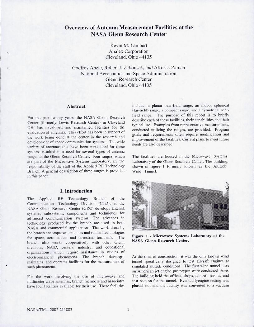
The facilities are housed 111 the Microwave Systems Laboratory of the Glenn Research Center. The building, shown in figure 1 formerly known as the Altitude Wind Tunnel.
Figure 1 - Microwave Systems Laboratory at the NASA Glenn Research Center.
At the time of construction, it was the only known wind tunnel specifically designed to test aircraft engines at simulated altitude conditions. The first wind tunnel tests on American jet engine prototypes were conducted there. The building held the offices, shops, control rooms, and test section for the tunnel. Eventuallyengine testing was phased out and the facility was converted to a vacuum

facility for rocket testing and spacecraft separation tests. This was followed by installation of a multi-axis gimbaling rig for Project Mercury astronaut training. In the early 1980' s, as the center continued its work in satellite communications with the beginning of the Advanced Communication Technology Satelli te Project, the need arose to have the capability to measure full scale, prototype, satellite antenna systems. Since these were planned to be large reflector antennas, a facili ty had to have enough space to accommodate them. The near-field technique fo r antenna measurement had matured by that ti me and the high bay area of the building shop offered ample room fo r a suitable vertical, near-field scanner. Therefore, the decision was made to construct this type of range.
The large near-field test range was completed and operations began in 1983 [1). This began the use of the building as an electromagnetic test facility. Research and development into microstrip patch antennas led to the conversion of the wind tunnel control room into a spherical (far-field) range in 1990. The building was expanded with an addition to the front in 199 1. This allowed for a larger near-field test section, a permanent control room for the near-field range, and offices fo r personnel supporting the acti vity in the building. A compact range was added in a basement storage room in 1994 to perform radar cross-section and antenna measurements. In 2002, due in part to an increasing workload in the far-field range, a cylindrical near-field test range was completed. The cylindrical range was located within the addition to the original building.
2. Planar Near-Field Antenna Facility
Although it has been used for many purposes, the primary function of the Planar Near-Field Antenna Facility is the measurement of large microwave antennas. The test volume envelope that the antenna system under test (AUT) must fit within is approximately 40' x 40' and 60' in height. The dimensions of the verti cal scan plane are 22' x 22' which defines the size of the largest antenna aperture that can be measured. The antennas are mounted to an azimuth over elevation positioner that has a total vertical load capacity of 30,000 lbs. A removable sidewall allows access from the preparation area for large structures. Antenna system installation and removal is assisted by an overhead crane. An image of the test area with a 2.7m reflector antenna installed is shown in figure 2.
NASAfTM-2002-211 883 2
Figure 2 - 2.7m Reflector Antenna in the Planar NearField Facility.
Generally, a typical test uses the AUT as the transmit antenna and a rectangular waveguide as the receiving probe antenna. The aperture fi eld of the AUT is sampled by performing a raster scan of hori zontal steps and continuous vertical movement at each step. The position of the probe at each data point is determined with a laser interferometer system.
An Agi lent 85 10C Network Analyzer is used as the receiver for this range. The basic test configuration, shown in figure 3, can provide measurements over a 4- 40 GHz freq uency range. The RF signal is generated in the range at the AUT. A reference signal is coupled from the RF input to the AUT and is down converted to a 20 MHz IF. The received signal from the probe is also down converted for a test channel of the receiver. To minimize LO phase changes and the weight of a cable as the probe is positioned, the LO is provided via a fi ber optic link from the control room. This room, which is adjacent to the test section, is shown in figure 4. The experiment control and data processing computers are also located there.
~ __ ._~ ___ __ J

AlJf Probe
85 10C Netwo rk An31yter
Figure 3 - Measurement Configuration for the Planar Near-Field Facility.
Figure 4 - View of the Planar Near-Field Facility Control Room from the Test Section.
Currentl y NASA per onnel are in the process of refurbishing the drive motors and controls for the scanner. In addition, the original la er interferometer po itioning system is obsolete and undergo ing an upgrade.
3. Far-Field Facility
The Far-Field Facility was developed to in ves tigate small , prototype microwave antennas such as reflector feeds , individual array elements and small phased arrays. Thu , thi s fac ili ty complements the function of the Planar NearField Facility. The range i located in a rectangular anechoic chamber that is approximately l 8'x 12' in cro -
section and 30' long. The usable range length is 24'. The fac il ity can be readil y configured to support any electromagnetic test ing that can utili ze the chamber. One permanent feature of the chamber is a centrally located,
NASAffM-2002-21l883 3
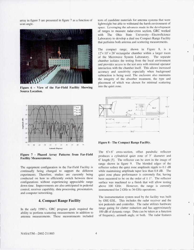
12" teel beam that ex tend through the length of the chamber. A movable cart attached to the beam provides a range di stance that can be continuously varied. Test equipment, including the pedestal for an AUT, can be located on a frame that attaches to the cart. An image which shows the chamber configured for receive pattern mea urements of a phased array antenna is shown in figure 5. Here the movable cart and a porti on of the test equipment are hidden behind the absorber panel. A view of the other end of the range, showing the transmjt source for thi s te t is shown in Figure 6. The location of the beam can be di cerned by the rai ed absorber ections a long the fl oor.
Figure 5 - Far Field Facility Test Zone Configured for Pattern Measurements.
The Far-Field Facil ity is cun'ently being used to support a wide range of tests to characterize the effects of e lectronica lly scanned pha ed array antennas on communication link performance [2-4]. The data requ ired from these te t are varied and thu equipment configurations are ins talled and adapted for each indi vid ual test. For standard antenna pattern and ga in measurements between 2-40 GHz, a configurat ion s imilar to figure 3 is used. The difference are that an HP841 0 Network Analyzer i used fo r the rece iver and rather than the fiber, a conventional microwave cable is u ed for the LO signal. E-pJane pattern at 19.85 GHz of the phased
----_. -- - - --
L
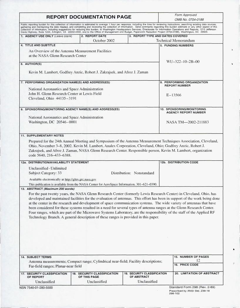
array in fi gure 5 are pre ented in fi gure 7 a a functi on of can angle.
Figure 6 - View of the Far-Field Facility Showing Source Location.
-5
-10
=- - 15
'" ~ "" .~ -20 Q.
~ -25
-30
-35
-40
~f\ ( A
rv I r t'\ II ,I'i1" M
~fll nl
V\ t\
v
II
( ~ ( \"/ I-~ \ \
~20 1' - _0
~
f, '" ,....
Vi~ 77 l~ V ~ 1/1
, rv'1 'r!' V{ ,. I~I j" ~ JI
-75 -60 -45 -30 -15 15 30 45 60 75
Azimuth (DegretS)
Figure 7 - Phased Array Patterns from Far-Field Facility Measurements.
The equipment configurati on in the Far-Field Facili ty is continuall y being changed to support the di fferent experiments. Therefore, studies are currently being conducted on how to effi cientl y witch between these configurati on without experienc ing appreciable range down time . Improvements are also anti cipated in pede tal control, receiver capabili ty, data proce sing, presentation, and computer networking.
4. Compact Range Facility
In the earl y 1990 's, GRC program goals required the abili ty to perform scattering measurements in addition to antenna measurement . The e measurements included
NASAlTM- 2002-2 11 883 4
tests of candidate materi als for antenna sy terns that were lightweight but able to withstand the harsh environment of space. Leveraging the advances made in the development
of range to mea ure radar-eros eetion, GRC worked with The Ohio State Uni versity-ElectroScience Laboratory to deve lop a dual use Compact Range Facili ty that perfo rm both antenna and scattering mea urements.
The compact range, shown in Figure 8, is a j 2'x 10' X 26' rectangular chamber within a larger room of the Microwave System Laboratory. The separate chamber isolate the te ting from the local environment and provides acces to the test area with minimal operator interacti on with the chamber itself. This allows increased accuracy and sen iti vity especiall y when background subtracti on i being u ed. The enclosure also maintains the integrity of the absorber treatment, the type and placement of which was chosen for minimal scatteri ng into the quiet zone.
1--------26.0·--------/
Figure 8 - The Compact Range Facility.
The 6'x 6' cros -secti on, off et paraboli c reflector
produces a cylindrica l quiet zone of 3' di ameter and
6' length [5]. The refl ector can be seen in the image of range hown in figure 9. The blended edges of the refl ector reduce the quiet zone amplitude ripple to 0. 1 dB while maintaining amplitude taper less than 0_8 dB . The quiet zone phase perfo rmance is ex tremely fl at, having been mea ured to be on the order of ± 1°_ The refl ector surface wa machined to a fini h that will allow te ting above 100 GHz. However, the range i current I y in trumented for 2 GHz to 36 GHz operation.
The in trumentati on system used by the fac ili ty was buil t by OSU-ESL. T hi includes the radar receiver and the test pedestals and controller. T he radar utili ze hard ware range gating for clutter reduction and ha approximately lOO dB of dynamic range. Data can be taken as a function of frequency, azimuth angle, or both . The radar feature
_.J

two-chan nel operation between 2-18 GHz, whi ch faci li tates the use of the range for antenna mea urement . The radar has a ingle channel from 18-36 GHz and antenna mea urement are enabled by di sconnecting the receive side of the T/R switch and connecting a cable from the receiving antenna. The polarization of the measu rement is varied by rotating the entire range reflector feed assembly. The a embly can be seen in the center of figure 9. The rotation is performed by a stepping motor that i commanded remote ly which also minimize operator interaction with the range. The foam co lumn shown in figure 9 and an azimuth rotator are used to upport lightweight antennas and material samples . A metal ogive shaped pede tal i used for heavier te t items.
Figure 9 - Interior of the Compact Range Facili ty.
Experiments are contro lled from the area adjacent to the chamber shown in fi gure J O. Computer resource for data torage, processing and presentati on are avai lable there a
well . An example of data measured in the compact range hown in figure 1 J .
NASAlTM-2002-211883 5
Figure 10 - Opera tions Area for the Compact Range Facility.
NASA intends to move the Compact Range Facility to a more accessible, above grade location within the Microwave Sy terns Laboratory. Planning for the move ha only recently been initiated and a time frame ha not been finalized.
-60
-{is
·,0
I I I
e- ·,5
<8 ·80 ~
1 ~ ." -85 = ." ·90 CD
~ -95
. 100
· IOS
/'Y. 1"
1\ F 'Y-+-
I .-
. 110
2
.."c:::. ~ ~
~ I
p; p<"
- Measured I-
- Exact
i - r-
8 10 12 Frequency (Ctlz)
I-
----
14 16 18
Figure 11 - Measured and Exact Radar Cross-Section of a 1116" Diameter Sphere.

5. Cylindrical Near-Field Facility
The Cylindrical ear-Field Facility occupies a
10'x II' x 9' high room within the Planar ear-Field Facility Control Room. The room, which was originally the computer room for the planar near-field range, has been converted into an anechoic chamber. A recently purchased NSI Model 600C-5 Cylindrical ear-Field Scanner System ha been in tailed in the room. A view of thi scanner in the room is hown in figure 12. The range is instrumented with an Agilent system consisting of an 8530A Microwave Receiver, 851lB Frequency Converter and 83650B Swept Signal Generator. This system provides for operation from 2 GHz to 40 GHz with different SI waveguide probes. Checkout of the facility and operator training is currently under way.
Figure 12 - The Cylindrical Near-Field Facility.
Thi faci lity is to be dedicated to ass ist in the re earch and development of small prototype antenna. The aperture size limitation on the AUT is approximately 10". It is expected that printed circuit, waveguide, horn, and wire antenna will be measured.
ASNTM-2002-21 1883 6
6. Summary
A description of the four antenna measurement facilitie in the ASA Glenn Re earch Center, Microwave Sy tem Laboratory has been presented. The e facilities provide NASA programs with a variety of option for obtaining performance information on microwave and millimeter wave antennas. The facilities are a fl ex ible a set that can be utilized by research organizations for not onl y antenna measurements but other types of e lectromagneti c experiment as wel l.
8. References
[I] Sharp, G.R , Zakrajsek, RI. , Kunath , R.R , Raquet, c.A. , Alexovitch, R.E., "Characteristics and Capabilities of the ASA Lewis Re earch Center High Precision 6.7- by 6.7-m Planar ear-Field Scanner", ASA TM-83785, October 1984.
[2] R. Acosta, S. Johnson, O. Sand , K. Lambert, "Characterization of Ka-Band Phased Array System: Modeling and Experimental Verification", AIAA 2(/" International Communication Satellite System Conference, May 2002.
[3] O. S. Sands, "Beam-Switch Transient Effect in the RF Path of the ICAPA Receive Phased Array Antenna", ubmitted for approval as a ASA Technical
Memorandum, NASA GRC, February 2002.
[4] R. Acosta, S. Johnson, O. Sand , K. Lambert, "KaBand Phased Array System Characterization", 1" Ka Band Utilization Conference, Santa Margherita Ligure, Italy, September 26-28, 200 I .
[5] Gupta, LJ., Burn ide, W.D. , "A 6'x 6' Compact Range Refl ector for 2 GHz and Above Frequencies", Technical Report 722657-1, The Ohio State University ElectroScience Laboratory, March 199 1.
I i
I
REPORT DOCUMENTATION PAGE I Form Approved
OMB No. 0704-0 188
Public reporting burden for this collection of information is estimated to average 1 hour per response, including the time for reviewing instructions, searching existing data sources, gathering and maintaining the data needed, and completing and reviewing the collection of information. Send comments regarding this burden estimate or any other aspect of this collection of information, including suggestions for reducing this burden , to Washington Headquarters Services, Directorate for Information Operations and Reports, 1215 Jefferson Davis Highway, Suite 1204, Arlington, VA 22202-4302, and to the Office of Management and Budget, Paperwork Reduction Project (0704-0188), Washington, DC 20503.
1. AGENCY USE ONLY (Leave blank) 12. REPORT DATE 1
3.
REPORT TYP E AND DATES COVERED
October 2002 Technical Memorandum 4. TIT LE A ND SUBTITLE 5. FUNDING NUMBERS
An Overview of the Antenna Measurement Facilities at the NASA Glenn Research Center
VVU- 322-10-2B-OO 6 . AUTHOR(S)
Kevin M. Lambert, Godfrey Anzic, Robert J. Zakrajsek, and Afroz 1. Zaman
7 . PERFORMING ORGANIZATION NA ME(S) AND ADDRESS(ES) 8. PERFORMING ORGANIZATION REPORT NUMBER
National Aeronautics and Space Administration John H. Glenn Research Center at Lewis Field E- 13566 Cleveland, Ohio 44135-3191
9 . SPONSORING/MONITORING AGENCY NAME(S) A ND ADDRESS(ES) 10 . SPONSORINGIMONIT ORING AGENCY REPORT NUMBER
National Aeronautics and Space Administration Washington, DC 20546- 0001 NASA TM-2002-211883
11- SUPPLEMENTARY NOTES
Prepared for the 24th Annual Meeting and Symposium of the Antenna Measurement Techniques Association, Cleveland , Ohio, November 3-8, 2002. Kevin M. Lambert, Analex Corporation, Cleveland, Ohio; Godfrey Anzic, Robert J_ Zakrajsek, and Afroz J. Zaman, NASA Glenn Research Center. Responsible person, Kevin M_ Lambert, organization code 5640, 216-433- 6388_
12a . DISTRIBUTION/AVAILABI LITY STATEMENT 12b. DISTR IBUTION CODE
Unclassified - Unlimited Subject Category: 33 Distribution: Nonstandard
Avai lable electronical ly at http://gltrs.grc.nasa.gov This publication is available from the NASA Center for AeroSpace Infom1ation. 301-62 1-0390.
13. ABSTRACT (Max imum 200 words)
For the past twenty years, the NASA Glenn Research Center (formerly Lewis Research Center) in Cleveland, Ohio, has developed and maintained facilities for the evaluation of antennas_ This effort has been in support of the work being done at the center in the research and development of space communication systems. The wide variety of antennas that have been considered for these systems resulted in a need for several types of antenna ranges at the Glenn Research Center. Four ranges, which are part of the Microwave Systems Laboratory, are the responsibility of the staff of the Applied RF Technology Branch. A general description of these ranges is provided in this paper.
14. SUBJECT TERMS 15. NUMBER OF PAGES
Antenna measurements; Compact range; Cylindrical near-field; Facility descriptions; 12
Far-field ranges; Planar-near field 16. PRICE CODE
17. SECURITY CLASSIFICATION 18. SECURITY CLASSIFICATION 19. SECURITY CLASSIFICATION 20. LIMITATION OF ABSTRACT OF REPORT OFTHIS PAGE OF ABSTRACT
Unclassified U nclassi fi ed Unclassified
NSN 7540-01-280-5500 Standard Form 2 98 (Rev. 2 -89) Prescribed by A N S I S td . Z39-18 2 98-102
--- ---- ----
•


![Design of Ionofree Micro Strip Quad Helix Antenna for ... · antenna, bifilar helices antenna, microstrip antenna, quadrafilar helix antenna. ... Helical antenna [1],[2] is broadband](https://static.fdocuments.in/doc/165x107/5b9506e809d3f2ea5c8b5a04/design-of-ionofree-micro-strip-quad-helix-antenna-for-antenna-bifilar-helices.jpg)