I ALTERNATORI AUTOREGOLATI SERIE ECSO - Mecc Alte · 95 - N°100-95 hergestellt. ... zen für die...
55
I ALTERNATORI AUTOREGOLATI SERIE ECSO ISTRUZIONI PER L’USO E LA MANUTENZIONE GB SELF- REGULATING ALTERNATORS SERIES ECSO OPERATING AND MAINTENANCE INSTRUCTIONS F ALTERNATEURS AUTO - REGULES SERIE ECSO MANUEL D’INSTRUCTION ET DE MAINTENANCE D SELBSTREGELNDER GENERATOR SERIE ECSO BETRIEBS-UND WARTUNGSANLEITUNG E ALTERNADORES AUTOREGULADOS SERIE ECSO INSTRUCCIONES PARA USO Y MANTENIMIENTO ECSO
Transcript of I ALTERNATORI AUTOREGOLATI SERIE ECSO - Mecc Alte · 95 - N°100-95 hergestellt. ... zen für die...

IALTERNATORI AUTOREGOLATI SERIE ECSO
ISTRUZIONI PER L’USO E LA MANUTENZIONEGB
SELF- REGULATING ALTERNATORS SERIES ECSOOPERATING AND MAINTENANCE INSTRUCTIONS
FALTERNATEURS AUTO - REGULES SERIE ECSO
MANUEL D’INSTRUCTION ET DE MAINTENANCED
SELBSTREGELNDER GENERATOR SERIE ECSOBETRIEBS-UND WARTUNGSANLEITUNG
EALTERNADORES AUTOREGULADOS SERIE ECSO
INSTRUCCIONES PARA USO Y MANTENIMIENTO
ECSO

ECSO MANUAL MAY 2009 REVISION 04
DESCRIZIONEMACCHINA
INDICE
La nuova serie di alternatori ECSO ha il si-stema di regolazione ed il regolatore elettronicobrevettati internazionalmente.Sono degli alternatori senza spazzole(brushless); possono essere sia monofasi chetrifasi e funzionare sia a 50 che a 60Hz.Il sistema base di regolazione e’ compoundtrifase, con la possibilita’ di inserire in qualsiasimomento e con semplici operazioni, il regola-tore elettronico AVIR, senza richiedere nes-suna minima modifica o taratura dell’alterna-tore.In questo modo l’alternatore fornisce tramite lacombinazione dei due sistemi di regola-zione,le prestazioni del compound trifase e la preci-sione della regolazione elettronica. Nel caso diun’anomalia al regolatore elettronico, l’alterna-tore continua a funzionare senza nessun inter-vento con la sola regolazione del compoundtrifase.I generatori sono costruiti in conformità alledirettive 98/37, 73/23, 89/336 e loro modifiche,alle norme CEI 2 - 3, EN 60034-1, IEC 34-1,VDE 0530, BS4999 - 5000, EN50081-1,EN50082-1, CAN/CSA-C22 N°14-95 - N°100-95. Le prove per la verifica della compatibilita’elettromagnetica sono state eseguite nellecondizioni prescritte dalle norme con il neutrocollegato a terra. Esecuzioni in accordo ad altrespecifiche possono essere eseguite su richie-sta del cliente.La struttura meccanica, sempre molto robu-sta, consente un facile accesso ai collega-menti e permette di eseguire le verifiche nellediverse parti altrettanto facilmente. La carcas-sa è realizzata in acciaio, gli scudi in ghisa,l’albero in acciaio C45 con ventola calettata. Ilgrado di protezione e’ IP21 (a richiesta è possi-bile realizzare un grado di protezione supe-riore).Gli isolamenti sono eseguiti in classe H, leimpregnazioni con resine epossidiche per leparti rotanti e trattamenti sottovuoto per le partidi piu’ elevata tensione, quali gli statori (a richie-sta trattamenti speciali).Nel campo dei radio disturbi, la produzione diserie soddisfa il grado “N” della norma VDE0875.
DESCRIZIONE MACCHINAPREMESSAIDENTIFICAZIONE MACCHINAVERIFICA ALLA CONSEGNAPRESCRIZIONI DI SICUREZZATRASPORTO E IMMAGAZZINAMENTOACCOPPIAMENTO MECCANICOACCOPPIAMENTO ELETTRICOAVVIAMENTO E ARRESTOPULIZIA E LUBRIFICAZIONEMANUTENZIONEANOMALIE E RIMEDIPARTI DI RICAMBIOTAVOLEDIMENSIONI DI INGOMBROGARANZIACENTRI DI ASSISTENZA
2
2 ÷ 34 ÷ 54 ÷ 54 ÷ 54 ÷ 1314 ÷ 1716 ÷ 2122 ÷ 2728 ÷ 2928 ÷ 2928 ÷ 3334 ÷ 3738 ÷ 3940 ÷ 4647 ÷ 49
5051 ÷ 54
PAG.
The regulating system and the electronic regu-lator of the new series of alternators ECSO areinternationally patended.These are brushless alternators; they can beeither single-phase or three-phase and work at50 or 60Hz. The basic regulation system isthree-phase compound, with the possibility ofconnecting the electronic regulator AVIR at anytime and by simple operations, without neces-sity of any alternator modification or calibration.This way, the alternator gives, by combinationof the two regulation systems, the performanceof the three-phase com-pound and the preci-sion of the electronic regulation.In case of anomaly of the electronic regulator,the alternator continues working without anyintervention with the only regulation of thethree-phase compound.The alternators are made in compliance withthe 98/37, 73/23, 89/336 directives and theiramendments, and the CEI 2 - 3, EN 60034-1,IEC 34 - 1, VDE 0530, BS4999 - 5000, EN50081-1, EN 50082-1, CAN/CSA-C22 N°14-95 - N°100-95 regulations.Tests to verify the electromagnetic compabi-lityhave been carried out in the foreseen condi-tions by the standards with the neutral connec-ted to the earth. On customer’s request alterna-tors can be manufactured according to diffe-rent specifications.The robust mechanical construction givesgood access to the generator output con-nections, and allows the user to inspect thevarious components with ease.The casing is made of steel, the shields of castiron, and the shaft of C45 steel and it has akeyed fan.The mechanical protection level meets stan-dard IP21 (upon request higher levels of pro-tection can be supplied).Insulation materials meet Class H requi-rements, and all rotating components areepossy resins impregnated, higher voltageparts, such as the stators, are vacuum-treated(special treatments are available on request).Radio interference suppression meets the re-quirements of VDE 0875 Grade “N” regula-tions.
MACHINE DESCRIPTIONINTRODUCTIONMACHINE IDENTIFICATIONINSPECTION ON DELIVERYSAFETY REQUIREMENTSTRANSPORT AND STORAGEMECHANICAL COUPLINGELECTRICAL CONNECTIONSSTARTING AND STOPPING OPERATIONSCLEANING AND LUBRICATIONMAINTENANCEDEFECTS AND REMEDIESSPARE PARTSTABLESOVERALL DIMENSIONSWARRANTYAFTER-SALES SERVICE
INDEX
MACHINEDESCRIPTION

ECSO MANUAL MAY 2009 REVISION 04
La nouvelle série d’alternateurs ECSO, pos-sède un système de régulation et un régula-teur electronique brevetés internationnale-ment. C’est une gamme d’alternateurs sansbague ni balais (brushless) qui fonctionne enmonophasé et triphasé aussi bien à 50 Hz qu’à 60 Hz. Le système de base de régulation estcompound triphasé, avec la possibilité d’inser-rer à tous moments avec une extrème simpli-cité le régulateur electronique AVIR, sans ef-fectuer de modification ou de réglage sur l’al-ternateur. De cette manière, l’alternateur four-nit au travers de la combinaison des deuxsystèmes, les prestations du compoundtriphasé avec la précision d’une machine àrégulation electronique. Dans le cas d’uneanomalie sur le régulateur electronique, l’alter-nateur continue à fonctionner sans interven-tion en compound triphasé. Les alternateurssont construits en conformité aux directivesCEE 98/37, 73/23, 89/336 et leurs modifica-tions, aux normes CEI 2 - 3, EN 60034-1, IEC34 - 1, VDE 0530, BS4999 - 5000, EN 50081-1, EN 50082-1, CAN/CSA-C22 N°14-95 -N°100-95. Les essais pour la verification de lacompatibilite electro-magnetique ont etè exe-cutés dans les conditions prescrites par lesnormes avec le neutre connecté à la masse.Les exécutions en accord avec d’autres spéci-fications peuvent être suivies sur demande duclient. La structure mécanique, toujours trésrobuste, permet un accés facile aux raccorde-ments et permet les vérifications des autresparties trés facilement. La carcasse est enacier, les flasques en fonte, l’arbre est en acierC45 avec ventilateur claveté. Le grade de pro-tection est IP21 (sur demande, il est possiblede réaliser un grade de protection supérieur).Les isolements sont de la classe H, les impré-gnations en vernis epoxy pour les parties tour-nantes et les parties plus élevées en tensioncomme les stators sont imprégnées sous videet pression (sur demande, nous pouvons exé-cuter des traitements spéciaux).Dans le domaine des antiparasitages, la pro-duction de série satisfait au grade “N” de lanorme VDE 0875.
Das Selbstregulierungsystem und der elektro-nischen Regler der neue Serie ECSO Gene-ratoren sind Weltpatentiert.Es handelt sich um Generatoren ohne Bür-sten (brushless); sie können einzelphasig oderdreiphasig sein und können mit 50 so wie mit60Hz funktionieren. Der Grundsystem istCompound dreiphasig, mit der Möglichkeit injeden Moment und mit einfache Arbeiten denelektronischen Regler AVIR einzustelen, ohneÄnderungen oder Tarierungen vorzunehmen.So gibt der Generator, durch die Verwendungder zwei Regulierung-systemen, die Dienstlei-stung des dreiphasig Compound und die Prä-zision der elektro-nische Reglung. Im Falle ei-ner Anomalie am elektronischen Regler arbei-tet der Generator weiter ohne Eingriff mit derCompound dreiphasig Regulierung weiter. DieGenera-toren sind in Ubereinstimmung mitden Bestimmungen 98/37 sowie mit 73/23und 89/336 und deren entsprechenden Ände-rungen und den Normen CEI 2 - 3, EN 60034-1, IEC 34 - 1, VDE 0530, BS4999 - 5000, EN50081-1, EN 50082-1, CAN/CSA-C22 N°14-95 - N°100-95 hergestellt.Die elektromagnetische vertraglichkeits prü-fungen wurden in den bei den normen vorge-schriebenen bedingungen mit dem sternpunktgeerdet ausgeführt. Ausführungen, die ande-ren als den angegebenen Spezifikationen ent-sprechen sollen, können auf Kundenanfragehergestellt werden. Die mechanische, sehr wi-derstandsfähige, robuste Struktur ermöglichtleichten Zugang zu den Verbindungen undAnschlüssen und erlaubt eine ebenso leichteKontrolle der verschiedenen Teile. DasGehäuse besteht aus Stahl, die (Schutz)schilde aus Gußeisen, die Welle aus C45-Stahl mit aufgezogenem Lüfterrad. DieSchutzklasse ist IP21 (auf Anfrage kann aucheine hohere Schutzklasse realisiert werden).Die Isolierungen entsprechen der Klasse H,die Imprägnierungen erfolgen mit Epoxidhar-zen für die drehbaren Teile, bzw, durchVakuumverfahren für die Teile, die erhöhterSpannung ausgesetzt sind, wie z.B. Ständer(auf Anfrage auch Sonderverfahren möglich).Bezüglich der Funkstörungen, entspricht dieProduk-tionsserie den Graden “N” der VDE0875 Normen.
La nueva serie de alternadores ECSO poseeel sistema de regulatión y el regulador electró-nico registrados con patente interna-cional.Se trata de alternadores sin escobil-las(brushless); pueden ser monofásicos o trifási-cos y funcionar tanto a 50 Hz como a 60 Hz.El sistema básico de regulación es de tipo“compound” trifásico, con la posibilidad deaplicar, en cualquier momento, y con una sim-ple operación, el regulador electrónico AVIR,sin necesidad de ninguna modifi-cación en elajuste de los parámetros del alternador. Deesta manera el alternador suministra, por me-dio de la combinación de los dos sistemas deregulación, las ventajas del compound trifá-sico junto con la precisión de la regulaciónelectrónica. En caso de un desperfecto en elregulador electrónico, el alternador continuaráa funcionar sin ningún tipo de intervención,con la regulación compound trifásica exclusi-vamente.Los generadores están construidos en confor-midad a las directivas 98/37, 73/23, 89/336 ysus modÍficas, normas CEI 2 - 3, EN 60034-1,IEC 34 - 1, VDE 0530, BS4999 - 5000, EN50081-1, EN 50082-1, CAN/CSA-C22 N°14-95 - N°100-95. Las pruebas de conformidad ala compatibilidad electromagnetica fueron rea-lizadas en las condiciones indicadas por lasnormas en decir con el neutro conectado atierra.Construcciones de acuerdo con otras especÍ-ficas podrán ser realizadas bajo pedido delcliente.La estructura mecánica, siempre de gran con-sistencia, permite un fácil acceso a los co-nexionados, como asÍ también un control delas diferentes partes de la misma. La carcasaestá construida en acero, las tapas en fundi-ción, el eje en acero C45 con ventilador aco-plado. El grado de protección es IP21 (a pe-dido es posible realizar un grado de protec-cÍon superior). Los aislantes son en clase H,las partes rotantes son impregnadas con resi-nas epoxidicas con tratamiento en vacÍo paralas partes que trabajan a mayor tensión,como son los estatores (a pedido tratamien-tos especiales).En el campo de la radio-interferencia, la pro-duccion de serie satisface el grado “N” de lasnormas VDE 0875.
DESCRIPTION DE LA MACHINEINTRODUCTIONIDENTIFICATION ALTERNATEURVERIFICATION A LA LIVRAISONPRESCRIPTIONS DE SECURITETRANSPORT ET STOCKAGEACCOUPLEMENT MECANIQUERACCORDEMENT ELECTRIQUEDEMARRAGE ET ARRETNETTOYAGE ET GRAISSAGEMANUTENTIONANOMALIES ET REPARATIONSPIECES DE RECHANGETABLEAUXENCOMBREMENTGARANTIECENTRES D’ASSISTANCE
DESCRIPCION MAQUINAACLARACIONIDENTIFICACION MAQUINACONTROL A LA ENTREGAPRECAUCIONES DE SEGURIDADTRANSPORTE Y DEPOSITOACLOPAMIENTO MECANICOCONEXION ELECTRICAARRANQUE Y PARADALIMPIEZA Y LUBRIFICACIONMANTENIMIENTOPROBLEMAS Y SOLUCIONESPARTES DE REPUESTOTABLASDIMENSIONES MAXIMASGARANTIACENTROS DE ASISTENCIA
MASCHINENBESCHREIBUNGVORWORTMASCHINENIDENTIFIKATIONÜBERPRÜFUNG BEI LIEFERUNGSICHERHEITSVORSCHRIFTENTRANSPORT UND LAGERUNGMECHANISCHER ANSCHLUßELEKTRISCHER ANSCHLUßANTRIEB UND STILLSETZUNGREINIGUNG UND SCHMIERUNGWARTUNGSTÖRUNGEN UND ABHILFEERSATZTEILETABELLENBAUMASSEGARANTIE / GEWÄHRLEISTUNGSERVICE-CENTER
INDEX INHALT INDICE
DESCRIPCIONMAQUINA
MASCHINENBESCHREIBUNG
DESCRIPTION DELA MACHINE
3

ECSO MANUAL MAY 2009 REVISION 04
PREMESSA
I generatori della serie ECSO, rispondono alledirettive CEE 73/23, 98/37, 89/336 e loro mo-difiche; pertanto non presentano pericolo perl’operatore, se installati, usati, manutenuti se-condo le istruzioni fornite dalla Mecc Alte e acondizione che i dispositivi di sicurezza sianotenuti in perfetta efficienza.
Per questa ragione occorre attenersi scrupo-losamente alle istruzioni indicate in questomanuale.
E’ vietata qualsiasi riproduzione di questomanuale.
Per qualsiasi comunicazione con la Mecc Alteo con i centri di assistenza autorizzati, citaresempre il tipo e il codice del generatore.
VERIFICA ALLACONSEGNA
IDENTIFICAZIONEMACCHINA
Prima di qualsiasi intervento di pulizia, lubri-ficazione o manutenzione, assicurarsi che ilmotore primario a cui e’ collegato il generatorenon sia in funzione, ma fermo e isolato dallesue fonti di energia.
Per fermare il generatore occorre seguire scru-polosamente la procedura di arresto del si-stema di trascinamento; il generatore non e’previsto di Stop/Emergenza, ma si arrestaistantaneamente in funzione al sistema di arre-sto predisposto dall’installatore.
PRESCRIZIONI DISICUREZZA
Alla consegna del generatore controllare conla bolla di accompagnamento che non cisiano danni o parti mancanti; nel caso infor-mare immediatamente lo spedizionere, l’assi-curazione, il rivenditore o la Mecc Alte.
4
The ECSO alternators comply with the 73/23,98/37, 89/336 EEC directives and their amen-dments; therefore they pose no danger to theoperator if they are installed, used and maintai-ned according to the instructions given byMecc Alte and provided the safety devices arekept in perfect working conditions.
Therefore a strict observance of these instruc-tions is required.
Any reproduction of this manual is forbidden.
Always indicate the generator type and codewhen contacting Mecc Alte or the authorizedafter-sales service centres.
When the alternator is delivered, check thatunit conforms with the delivery note and en-sure that there are no damaged or defectiveparts; should there be any, please inform theforwarding agent, the insurance company, theseller or Mecc Alte immediately.
Before any cleaning, lubrication or mainte-nance operation, ensure that the generator isstationary and disconnected from the powersupply.
When stopping the generator, ensure thecompliance with the procedures for stoppingthe prime mover.The generator, in fact, has no EmergencyStop, but is controlled by the device arrangedby the installer.
INTRODUCTION
MACHINEIDENTIFICATION
INSPECTION ONDELIVERY
SAFETYREQUIREMENTS

ECSO MANUAL MAY 2009 REVISION 04
Les alternateurs de la série ECSO répondentaux directives CEE 73/23, 98/37, 89/336 etleurs modifications. Toutefois, ils ne présententaucun danger pour l’utilisateur si l’installation,l’utilisation, les manutentions suivent les in-structions fournies par Mecc Alte et à conditionque les dispositifs de protection soient tenusen parfait état de marche.
Pour cette raison, il faut se conformer scrupu-leusement aux instructions indiquées dans cemanuel.
Il est interdit de reproduire quoique ce soit dece manuel.
Die Generatoren entsprechen den EG - Be-stimmugen 73/23, 98/37, 89/336 und derenentsprechenden Änderungen; aus diesemGrunde stellen sie keinerlei Gefahr für denBediener dar, sofern sie in Übereinstimmungmit den von Mecc Alte vorgeschriebenenAnweisungen installiert, verwendet undgewartet werden und unter der Bedingung,daß die Schutzvorrichtungen stets in einemvoll funktionstüchtigen Zustand gehalten wer-den.Aus den oben genannten Grunden ist es er-forderlich, sich streng an die in diesem Hand-buch angegebenen Anweisungen zu halten.
Jegliche Form der Verbreitung und Repro-duktion dieses Handbuchs ist verboten.
Los generadores de la serie ECSO, respon-den a las directivas CEE 73/23, 98/37,89/336 y a sus respectivas modificaciones,por lo tanto no se presentan peligros para eloperador, si instalados, usados y manteni-dos según las instrucciones dadas por laMECC ALTE y con la condición que losdispositivos de seguridad sean mantenidosen una condición de perfecta eficiencia.
Por esta razón es necesario adecuarse a laperfección a las instrucciónes indicadas eneste manual.
Se prohibe la reproducción total o parcial deeste manual.
Avant une quelconque intervention de net-toyage, lubrification ou manutention, le moteuravec lequel est accouplé l’alternateur ne doitpas être en fonctionnement mais coupé deses sources d’énergie.
Pour arrêter un alternateur, il faut suivre scru-puleusement la procédure d’arrêt du systèmed’entraînement, l’alternateur n’est pas pourvud’arrêt d’urgence, mais il s’arrête instantané-ment en fonction du système d’arrêt prévu parl’installateur.
Vor jedem Eingriff für Reinigung, Schmierungoder Wartung, muß der Hauptmotor, an dender Generator angeschlossen ist, außer Be-trieb gesetzt werden; er muß stillstehen undvon seinen Energiequellen isoliert werden.Um dem Generator zu stoppen, ist es erfor-derlich genauestens das stellverfahren fürdas Zugsystem einzuhalten; der Generator istnicht mit einem Sicherheits-abschalter(“NOTAUS”) versehen, sondern er stoppt un-mittelbar in Abhängigkeit von dem Abschal-tsystem, das vom Hersteller vorgesehen ist.
Antes de cualquier tipo de operación de lim-pieza, lubrificación o mantenimiento, el motorprimario al cual está acoplado el generadorno debe estar en funcionamiento, el mismodeberá estar inmóvil y aislado de sus fuentesde energía.Para detener el generador es necesario se-guir escrupolosamente los procedimientosde detención del sistema de arrastre; el ge-nerador no posee un Stop/Emergencia, puésel mismo se detiene instantaneamente enfunción del sistema de stop preparado por elinstalador.
Pour toute demande auprès de Mecc Alte ouauprès des centres agrées autorisés, citertoujours le type et le code de l’alternateur.
Für Mitteilungen an Mecc Alte oder an dieautorisierten Service-Zentralen, ist derGeneratorentyp und der Code anzugeben.
Para cualquier tipo de comunicación con laMECC ALTE o con los centros de reparaciónautorizados, indicar siempre el tipo y el códigodel generador.
A la livraison de l’alternateur, contrôler avec lebon de livraison qu’il n’y a aucun dommage oude pièces manquantes; si c’est le cas, informerimmédiatement l’expéditeur, l’assu-reur, le re-vendeur ou Mecc Alte.
Bei Lieferung des Generators ist anhand desLieferscheins dieser auf Schäden, bzw. auffehlende Teile hin zu überprüfen; in diesemFalle sind der Spediteur, die Versicherung,der Wiederverkäufer oder Mecc Alte um-gehend darüber zu informieren.
A la entraga del generador, controlar juntocon la factura que no existan defectos o pie-zas faltantes; en caso contrario informar in-mediatamente la empresa de transportes, lacompañia de seguros, el revendedor o laMecc Alte.
INTRODUCTION VORWORT ACLARACION
IDENTIFICATIONDE LA MACHINE
MASCHINENIDENTIFIKATION
IDENTIFICACIONMAQUINA
CONTROL A LAENTREGA
ÜBERPRUFÜNGBEI LIEFERUNG
VERIFICATIONA LA LIVRAISON
PRESCRIPTIONSDE SECURITE
SICHERHEITSVORSCHRIFTEN
PRECAUCIONESDE SEGURIDAD
5

ECSO MANUAL MAY 2009 REVISION 04
6
IMPORTANTThis symbol warns the personnelconcerned that the described operationmay cause damages to the machine if it isnot carried out according to the safetystandards.
CAUTIONThis symbol warns the personnelconcerned that the described operationmay cause damages to the machine and/orinjures to the personnel if it is not carriedout according to the safety standards.
WARNINGThis symbol warns the personnelconcerned that the described operationmay cause serious injuries or death to thepersonnel if it is not carried out accordingto the safety standards.
DANGERThis symbol warns the personnelconcerned that the described operationmay immediately cause serious injuries ordeath to the personnel if it is not carried outaccording to the safety standards.
SAFETYREQUIREMENTS
Symbols having specific meanings have beenused throughout this instruction and mainte-nance manual.
CONVENTIONAL SYMBOLS ANDSYMBOL DESCRIPTION
Durante la consultazione del presentemanuale d’uso e manutenzione troveretealcuni simboli; questi hanno un precisosignificato.
PRESCRIZIONIDI SICUREZZA
SIMBOLOGIA CONVENZIONALEE SUA DEFINIZIONE
IMPORTANTESegnala al personale interessato che l’ope-razione descritta presenta un rischio chepuò avere come conseguenza un dannoalla macchina, se non effettuata nel ri-spetto delle normative di sicurezza.
ACCORTEZZASegnala al personale interessato che l’ope-razione descritta presenta un rischio chepuò avere come conseguenza un dannoalla macchina e/o lesioni al personalestesso, se non effettuata nel rispetto dellenormative di sicurezza.
AVVERTIMENTOSegnala al personale interessato che l’ope-razione descritta presenta un rischio chepuò avere come conseguenza lesioni gravio morte, se non effettuata nel rispetto dellenormative di sicurezza.
PERICOLOSegnala al personale interessato che l’ope-razione descritta presenta un rischio im-mediato che ha come conseguenza lesionigravi o morte, se non effettuata nel rispettodelle normative di sicurezza.
IMPORTANTEIMPORTANT
WICHTIG

ECSO MANUAL MAY 2009 REVISION 047
WICHTIGSignalisieren Sie dem zuständigenPersonal, daß die beschriebene Arbeit einRisiko darstellt, welches Schäden an derMaschine zur Folge haben kann; falls dieArbeit nicht unter voller Beachtung derSicherheitsvorschriften erfolgt.
HINWEISSignalisieren Sie dem zuständigenPersonal, daß die beschriebene Arbeit einRisiko darstellt, welches Schäden an derMaschine und/oder Verletzungen desPersonales selbst zur Folge haben kann;falls die Arbeit nicht unter vollerBeachtung der Sicherheitsvorschriftenerfolgt.
WARNHINWEISWarnsignale der interessierte Personal,daß die beschriebene Operation eineGefahr vorstellt, die er haben kann wiewenn ernste Verletzungen derKonsequenz oder Tote, durchgeführtnicht im Respekt der Notnormen.
GEFAHRHaltesignale der interessierte Personal,daß die beschriebene Operation einesofortige Gefahr vorstellt, die wie wennernste Verletzungen der Konsequenzoder hat Tote, durchgeführt nicht imRespekt der Notnormen.
PRESCRIPTIONSDE SECURITE
IMPORTANTSigne au personnel interessé que l’opera-tion décrite presente, une risque qu’il peutavoir comme conséquence une domageau la machine, si n’effectué pas dans lerespect des normes de securité.
ADRESSESigne au personnel interessé que l’opera-tion décrite presente, une risque qu’il peutavoir comme conséquence une domageau la machine et/ou lésiones graves aupersonnel même, si n’effectué pas dans lerespect des normes de securité.
AVVERTISSEMENTSigne au personnel intéressé que l'exécu-tion décrite présente une risque qu'il peutavoir comme consèquence une domageou lésiones graves ou mort, si n’effectuépas dans le respect des normes de secu-rité.
DANGERSigne au personnel intéressé que l'exécu-tion décrite présente une risque immédiatqu'il a comme consèquence une domageou lésiones graves ou mort, si n’effectuépas dans le respect des normes de secu-rité.
Pendant la consultation du présent manueld’instruction et de mantenance, vous trouverezquelques symboles; ces ont une précis signifi-cation.
SIMBOLIQUE CONVENTIONNELET DEFINITION
Beim Nachschlagen in diesem Handbuchzur Bedienung und Wartung sind hier und daeinige Symbole zu finden; diese haben einebestimmte Bedeutung.
ALLGEMEIN ÜBLICHE SYMBOLIKUND IHRE DEFINITION
SICHERHEITSVORSCRIFTEN
PRECAUCIONESDE SEGURIDAD
IMPORTANTESigna a el personal interesado que eloperation descrita presenta, une riesgoque puede hacer como consecuencia unedaño a la maquina, se no efectuada en elrespecto de les normatives de securidad.
AGUDEZASigna a el personal interesado que eloperation descrita presenta, une riesgoque puede hacer como consecuencia unedaño a la maquina y/ou lésiones a elpersoanl mismo, se no efectuada en elrespecto de les normatives de securidad.
ADVERTIMIENTOSeñales a los personales interesado quela operación descrita introduce un riesgoque él pueda tener como lesiones omuertos serios de la consecuencia, si noestá realizado en el respecto de llesnormatives de securidad.
PELIGROSeñales a los personales interesado quela operación descrita introduce un riesgoinmediato que tenga como lesiones omuertos seriosn de la consecuencia, si noestá realizado en el respecto de lesnormatives de securidad.
Durante la consultaciòn de el presente ma-nual uso y manutention, aquìy allì hallerà algu-nes simbolos; Esos ont une preciso signifi-cado.
SIMBOLOGIA CONVENCIONAL YSUAS DEFINICION
ECSO MANUAL MAY 2009 REVISION 04
8
SAFETYREQUIREMENTS
PRESCRIZIONIDI SICUREZZA
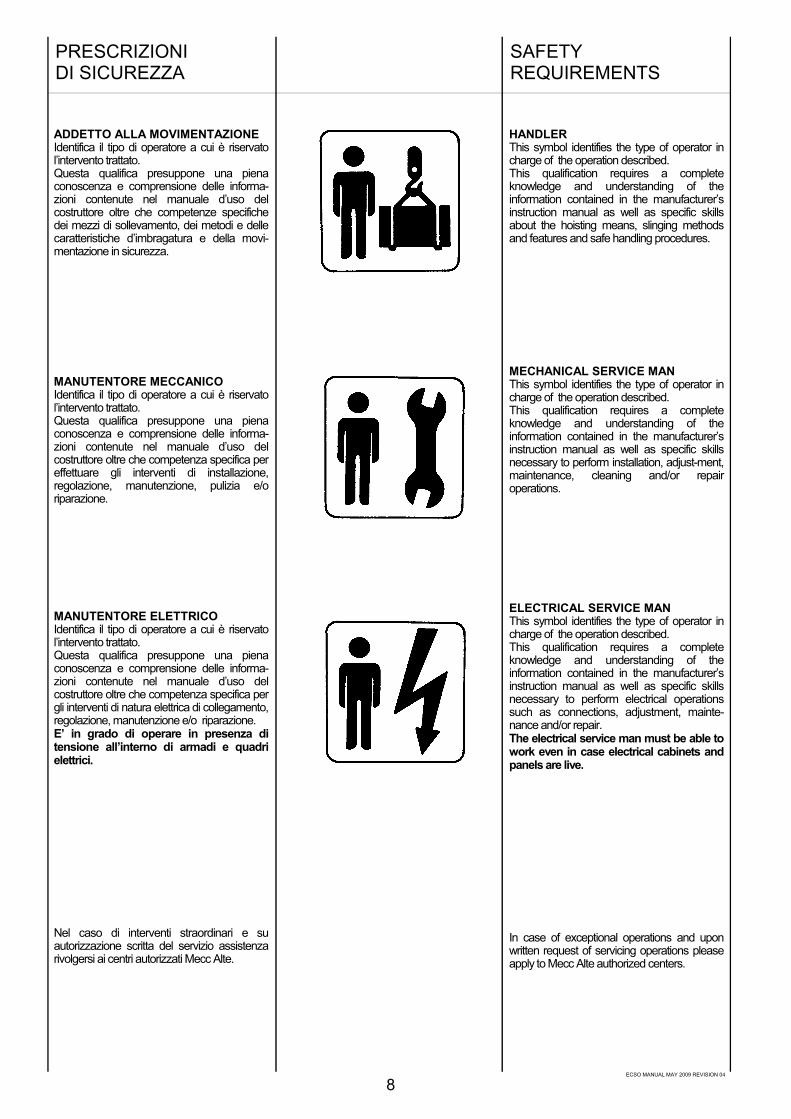
HANDLERThis symbol identifies the type of operator incharge of the operation described.This qualification requires a completeknowledge and understanding of theinformation contained in the manufacturer’sinstruction manual as well as specific skillsabout the hoisting means, slinging methodsand features and safe handling procedures.
MECHANICAL SERVICE MANThis symbol identifies the type of operator incharge of the operation described.This qualification requires a completeknowledge and understanding of theinformation contained in the manufacturer’sinstruction manual as well as specific skillsnecessary to perform installation, adjust-ment,maintenance, cleaning and/or repairoperations.
ELECTRICAL SERVICE MANThis symbol identifies the type of operator incharge of the operation described.This qualification requires a completeknowledge and understanding of theinformation contained in the manufacturer’sinstruction manual as well as specific skillsnecessary to perform electrical operationssuch as connections, adjustment, mainte-nance and/or repair.The electrical service man must be able towork even in case electrical cabinets andpanels are live.
In case of exceptional operations and uponwritten request of servicing operations pleaseapply to Mecc Alte authorized centers.
ADDETTO ALLA MOVIMENTAZIONEIdentifica il tipo di operatore a cui è riservatol’intervento trattato.Questa qualifica presuppone una pienaconoscenza e comprensione delle informa-zioni contenute nel manuale d’uso delcostruttore oltre che competenze specifichedei mezzi di sollevamento, dei metodi e dellecaratteristiche d’imbragatura e della movi-mentazione in sicurezza.
MANUTENTORE MECCANICOIdentifica il tipo di operatore a cui è riservatol’intervento trattato.Questa qualifica presuppone una pienaconoscenza e comprensione delle informa-zioni contenute nel manuale d’uso delcostruttore oltre che competenza specifica pereffettuare gli interventi di installazione,regolazione, manutenzione, pulizia e/oriparazione.
MANUTENTORE ELETTRICOIdentifica il tipo di operatore a cui è riservatol’intervento trattato.Questa qualifica presuppone una pienaconoscenza e comprensione delle informa-zioni contenute nel manuale d’uso delcostruttore oltre che competenza specifica pergli interventi di natura elettrica di collegamento,regolazione, manutenzione e/o riparazione.E’ in grado di operare in presenza ditensione all’interno di armadi e quadrielettrici.
Nel caso di interventi straordinari e suautorizzazione scritta del servizio assistenzarivolgersi ai centri autorizzati Mecc Alte.
ECSO MANUAL MAY 2009 REVISION 04
PRECAUCIONESDE SEGURIDAD
9
PRESCRIPTIONSDE SECURITE
SICHERHEITSVORSCRIFTEN
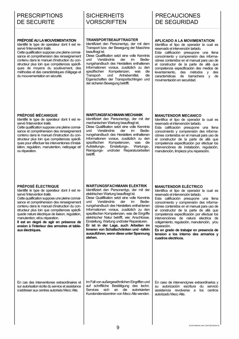
APLICADO A LA MOVIMENTATIONIdentifica el tipo de operador la cual esreservado el intervenciòn tartado.Esta calificaciòn presupone una llenaconocimiento y comprensiòn des informa-ciònes contenidos en el manual para uso deel constructor de la parte de allà quecompetencia especificaciòn des medios deleventamiento, des métodos y descaracterìsticas de barrachera y demovimentaciòn en securidad.
MANUTENDOR MECANICOIdentifica el tipo de operador la cual esreservado el intervenciòn tartado.Esta calificaciòn presupone una llenaconocimiento y comprensiòn des informa-ciònes contenidos en el manual para uso deel constructor de la parte de allà quecompetencia especificaciòn por efectuar losintervenciònes de instalaciòn, regulaciòn,manutenciòn, limpieza y/ou reparaciòn.
MANUTENDOR ELÉCTRICOIdentifica el tipo de operador la cual esreservado el intervenciòn tartado.Esta calificaciòn presupone una llenaconocimiento y comprensiòn des informa-ciònes contenidos en el manual para uso deel constructor de la parte de allà quecompetencia especificaciòn por efectuar losintervenciònes de natura electrica decoligamiento, regulaciòn, manutenciòn, y/oureparaciòn.Es en grado de trabajar en presencia detension a los interno des armarios ycuadros electricos.
En caso de intervenciçnes extraordinarios ysu autorizaciòn escritura du servicioassistencia revolverse a los centrosautorizado Mecc Alte.
TRANSPORTBEAUFTRAGTERIdentifiziert den Personentyp, der mit demTransport bzw. der Bewegung der Maschinebeauftragt ist.Diese Qualifikation setzt eine volle Kenntnisund Verständnis der im Bedie-nungshandbuch des Herstellers enthaltenenInformationen voraus, zusätzlich zu denspezifischen Kompetenzen, was dieTransport- und Anhebemittel, dieEigenschaften der Transportschlingen undder sicheren Bewegung betrifft.
WARTUNGSFACHMANN MECHANIKIdentifiziert den Personentyp, der mit dermechanischen Wartung beauftragt ist.Diese Qualifikation setzt eine volle Kenntnisund Verständnis der im Bedie-nungshandbuch des Herstellers enthaltenenInformationen voraus, zusätzlich zu denspezifischen Kompetenzen, was dieAufstellungs-, Einstellungs-, Wartungs-,Reinigungs- und/oder Reparaturarbeitenbetrifft.
WARTUNGSFACHMANN ELEKTRIKIdentifiziert den Personentyp, der mit derelektrischen Wartung beauftragt ist.Diese Qualifikation setzt eine volle Kenntnisund Verständnis der im Bedie-nungshandbuch des Herstellers enthal-tenenInformationen voraus, zusätzlich zu denspezifischen Kompetenzen, was die Eingriffeelektrischer Natur betrifft, wie: Anschlüsse,Einstellung, Wartung und/oder Reparaturen.Er ist in der Lage, auch Arbeiten imInneren von Schaltschränken und –tafelnauszuführen, wenn diese unter Spannungstehen.
Im Fall von außergewöhnlichen Eingriffen undauf schriftliche Bestätigung des techn.Services sich an die autorisiertenKundendienstzentren von Mecc Alte wenden.
PRÉPOSÉ AU LA MOUVEMENTATIONIdentifié le type de operateur dont il est re-servé l’intervention traité.Cette qualification suppose une pleine connai-sance et compréhension des renseignementcontenu dans le manuel d’instruction du con-structeur plus loin que compétences spécifi-ques de moyens du soulévement, desméthodes et des caractéristiques d’éligage etdu mouvementation en sécurité.
PRÉPOSÉ MÉCANIQUEIdentifié le type de operateur dont il est re-servé l’intervention traité.Cette qualification suppose une pleine connai-sance et compréhension des renseignementcontenu dans le manuel d’instruction du con-structeur plus loin que compétences spécifi-ques pour effectuer les interventiones d’instal-lation, regulation, manutention, nettoyage et/ou réparation.
PRÉPOSÉ ÉLECTRIQUEIdentifié le type de operateur dont il est re-servé l’intervention traité.Cette qualification suppose une pleine connai-sance et compréhension des renseignementcontenu dans le manuel d’instruction du con-structeur plus loin que compétences spécifi-quede nature électrique de liaison, regulation,manutention, et/ou réparation.Il est en degré de agir en présence deension à l’interieur des armoires et table-aux électriques.
En cas des interventiones extraordinaires etsur autorisation écrite du service et assistances’addreser aux centres autorisés Mecc Alte.

ECSO MANUAL MAY 2009 REVISION 04
Al momento dell’installazione le normeprevedono che il generatore sia col-legato a terra.Per questa ragione assicurarsi chel’impianto di messa a terra sia efficienteed in conformita’ con le direttive delpaese dove il generatore sara’ instal-lato.
ATTENZIONEL’INSTALLATORE FINALE E’ RE-SPONSABILE DELLA PREDISPO-SIZIONE DI TUTTE LE PROTEZIONI(DISPOSITIVI DI SEZIONAMENTO,PROTEZIONI CONTRO I CONTATTIDIRETTI E INDIRETTI, PROTEZIONICONTRO SOVRACORRENTI ESOVRATENSIONI, ARRESTO DIEMERGENZA ECC.) NECESSARIEPER RENDERE CONFORME ILMACCHINARIO E L’IMPIANTO UTI-LIZZATORE, ALLE VIGENTI NORMEDI SICUREZZA INTERNAZIONALI /EUROPEE
Per la movimentazione dei generatoridisimballati usare sempre ed esclu-sivamente gli appositi golfari.Utilizzare funi di portata adeguata(tav.11 pag. 46) senza sollevare ilgeneratore troppo dal pavimento (max30 cm.).
Alla fine del periodo di vita dellamacchina, rivolgersi alle agenzie dismaltimento materiali ferrosi e nondisperderne parti nell’ambiente.
Gli addetti all’installazione, conduzionee manutenzione del generatore devonoessere tecnici adeguatamente qualificatie che conoscano le caratteristiche deigeneratori.
Le persone addette alla movimen-tazione devono sempre indossareguanti da lavoro e scarpe antinfortuni-stiche. Qualora il generatore o l’interoimpianto debba essere sollevato daterra, gli operatori devono usare uncasco protettivo.
Il generatore va installato in un ambienteaerato ( tav.11 pag. 46).Se non c’e’ sufficiente aria oltre al malfunzionamento esiste pericolo di surri-scaldamento.Sulla porta di ingresso del locale ci deveessere un cartello indicante il divieto diaccesso alle persone non autorizzate.
Assicurarsi che il basamento delgeneratore e del motore primario siacalcolato per sopportarne il peso e tuttigli eventuali sforzi dovuti al funzio-namento.
L’installatore deve collegare la mac-china perfettamente in asse al motoreprimario; in caso contrario l’insieme puo’generare vibrazioni pericolose.
La macchina e’ stata progettata pergarantire la potenza nominale inambienti con temperatura massima di40 C° e altitudine inferiore ai 1000 metri;per condizioni diverse vedere il catalogocommerciale (depliant).
PRESCRIZIONI DISICUREZZA
10
Before installing the generator, ar-rangements must be made to earth themachine in compliance with anyrelevant electrical regulations. This isthe reason why you must make surethat the grounding system is in goodconditions and in compliance with theregulations of the country where thegenerator will be installed.CAUTIONTHE FINAL INSTALLER IS RE-SPONSIBLE FOR THE INSTAL-LATION OF ALL THE PROTECTIONS(SECTIONING DEVICES, PROTEC-TIONS AGAINST DIRECT ANDINDIRECT CONTACTS, OVERCUR-RENT AND OVERVOLTAGE PRO-TECTIONS, EMERGENCY STOP,ETC.) NECESSARY FOR THEMACHINE TO COMPLY WITH THEEXISTING INTERNATIONAL/EURO-PEAN SAFETY REGULATIONS.
For handling the unpacked generators,always use the special eyebolts only;use ropes having a suitable carryingcapacity (table 11, page 46) and do notlift the generator too much from thefloor (max 30 cm ).
When the machine is worn cut, contactthe companies in charge of the disposalof ferrous material and do not throwaway its parts into the environment.The operators in charge of theinstallation, operation and mainte-nance of the generators must be skilledtechnicians who know the charac-teristics of the generators.The people in charge of the handlingmust always wear work gloves andsafety shoes. In case the generator orthe whole plant must be lifted from thefloor, the operators must wear a safetyhelmet.
The generator must be installed in anairy room (table 11, page 46).If there is not enough air, a malfunctionor an overheating may occur.All entry doors into generator roomshould be clearly marked “Authorizedpersons only”.
Make sure that gen-set foundations andbaseframe are suitable to bear thecombined weight of the alternators andprime mover.
The alternator should be securelyconnected and perfectly aligned withthe prime mover, otherwise dangerousvibrations may occur.
The machine has been designed toensure the rated output when it isinstalled in rooms having a maxtemperature of 40°C and at an altitudenot exceeding 1000 meters; in case ofdifferent conditions, please makereference to our catalogue (brochure).
SAFETYREQUIREMENTS

ECSO MANUAL MAY 2009 REVISION 04
11
Au moment de l'installation, les normesprévoient que l'alternateur soit relié à laterre. Pour cette raison, s'assurer quel'installation de mise à la terre fonctionnebien et soit en conformité avec lesdirectives du pays ou le générateur serainstallé.
ATTENTIONL’INSTALLATEUR FINAL EST RE-SPONSABLE DE LA MISE EN PLACEDE TOUTES LES PROTECTIONSNÉCESSAIRES (DISPOSITIFS DEPROTECTION ET DE COUPURE,PROTECTIONS CONTRE LESCONTACTS DIRECTS ET INDIRECTS,PROTECTIONS CONTRE LES SUR-CHARGES ET LES SURTENSIONS,ARRÊT D’URGENCE ETC.), POURRENDRE CONFORME LE MATÉRIELET SON IMPLANTATION AUXNORMES DE SÉCURITÉ INTERNA-TIONALES ET EUROPÉENNES ENVIGUEUR.
Pour le déplacement des alternateursdesemballés, utiliser toujours et exclu-sivement les points d'encrage, utiliser lesmoyens de levage adéquats (tab. 11, pag.46) sans trop soulever l'alternateur du sol(max. 30 cm).
A la fin de la période de vie de la machine,s'adresser aux organismes de recyclagedu matériel concerné.
Les ouvriers, conducteurs et manu-tentionnaires de l'alternateur doivent êtretechniquement qualifiés et connaître lescaractéristiques du générateur.
Les personnes employées à la manu-tention doivent avoir des gants et deschaussures de sécurité. Dans le cas oul'alternateur ou le groupe électrogènedoivent être soulevé de terre, lesopérateurs doivent utiliser un casque deprotection.
L'alternateur doit être installé dans unendroit aéré (tab.11, pag.46). Si la quantitéd'air n'est pas suffisante, outre un mauvaisfonctionnement, il existe aussi un risquede surchauffe.Sur la porte d'entrée du local il doit y avoirun écriteau indiquant "entrée interdite auxpersonnes non autorisees".
S' assurer que le chassis, support del'alternateur et du moteur, est calculé poursupporter la masse totale.
L'installateur doit monter la machineparfaitement dans l'axe du moteurd'entrainement.Dans le cas contraire, l'ensemble peutgénérer des vibrations dangereuses.
La machine est prévue pour garantir sapuissance nominale à une température ambiantede 40°C max, et pour une altitude inférieure à1000 m.Pour des conditions différentes, voir le cataloguecommercial (dépliant).
Al momento de la instalación, las normaspreveen la conexión a tierra del generador.Por lotanto es necesario que la instalación de puesta atierra sea eficiente y en conformidad con lasdirectivas del país donde el generador serámontado.
ATENCIONEL INSTALADOR FINAL ESRESPONSABLE DEL MONTAJE DETODAS LAS PROTECCIONES(DISPOSITIVOS DE SECCIONA-MIENTO, PROTECCIONES CONTRACONTACTOS DIRECTOS E INDI-RECTOS, PROTECCIONES CONTRASOBRECORRIENTE Y SOBRE-TENSION, PARADA DE EMER-GENCIA, ETC.), NECESARIAS PARAPRODUCIR LA CONFORMIDAD DELAS MAQUINAS Y LA INSTALACIONCON LAS NORMAS VIGENTES DESEGURIDAD INTERNACIONALES YEUROPEAS.Para mover los generadores desembalados,usar siempre y exclusivamente loscorrespondientes ganchos que poseen losmismos. Utilizar correas de resistenciaadecuada (tab. 11, pag. 46) sin necesidad deelevar demasiado el generador del pavimento(max 30 cm).Al final del periodo de vida útil de la máquina,dirigirse a una agencia de reciclaje de materialesferrosos, de manera de no perder partes en elambiente.Las personas dedicadas a la instalación,transporte y mantenimiento del generadordeberán ser técnicos adecuadamentecalificados y que conozcan las características delos generadores.Las personas dedicadas al transporte deberánusar siempre guantes de trabajo y zapatos deseguridad. Siempre que el generador o elequipo completo sea elevado del suelo, losoperadores deberán usar cascos de protección.
El generador debe ser instalado en un ambienteaireado (tab. 11, pag. 46).Si no hoy suficiente ventilación, además del malfuncionamiento existirá el peligro desobrecalentamiento. A la puerta de ingreso dellocal se deberá colocar un cartel que prohiba elacceso a las personas no autorizadas.
Asegurarse que la base de apoyo delgenerador y del motor primario sean calculadaspara soportar el peso total.
El instalador deberá acoplar el generadorcoaxialmente con el motor primario, en casocontrario, todo el conjunto podrá tener peligrosasvibraciones.
La máquina eléctrica fue diseñada paragarantizar la potencia nominal con unatemperatura ambiente máxima de 40 °C unaaltitud inferior a 1000 m; para condicionesdiferentes ver el catálogo comercial (depliant).
Bei der installation ist, gemäß Vorschriften,darauf zu achten, daß der Generator geerdetwird. Aus diesem Grunde ist es erforderlichsicherzustellen, daß die Erdungsanlageleistungsfähig ist und mit den Vorschriften desLandes, in dem der Generator installiert wird,übereinstimmt.
ACHTUNGDER ENDMONTEUR IST VERANT-WORTLICH FÜR DIE VOREINSTEL-LUNG UND VORBEREITUNG ALLERS C H U T Z V O R R I C H T U N G E N( T R E N N V O R R I C H T U N G E N ,SCHUTZVORRICHTUNGEN GEGENDIREKTUND INDIREKTKONTAKT,SCHUTZVORRICHTUNGEN GEGENÜBERSTROM UND ÜBERSPAN-NUNG, NOTAUS, ETC.), DIEMACHINE UND DIE ANLAGE DESANWENDERS AN DIE GÜLTIGENINTERNATIONALEN UND EURO-PÄISCHEN SICHERHEITSVOR-SCHRIFTEN ANZUPASSEN.
Für den Transport der nicht verpacktenGeneratoren sind immer und ausschließlichdie entsprechend geeigneten Transportösenzu verwenden (tabel 11, Seite 46). Es sindSeile mit geeigneter Tragfähigkeit zuverwenden, ohne den Generator zu sehr vonder Bodenfläche anzuheben (max. 30 cm).
Am Ende der Lebendsdauer der Maschinenist sich an die Entsorgungsunternehmen fürEisenmaterialen zu wenden; Teile dürfennicht einfach weggeworfen werden.
Das für installation, Bedienung und Wartungzuständige Personal muß aus entsprechendqualifizierten Technikern bestehen, die dieEigenschaften des Generators genaukennen.
Die für den Transport zuständigen Personenhaben stets Arbeitshandschuhe undSchuhwerk gemäß denUnfallverhütungsvorschriften zu tragen.Sofern der Generator oder die gesamteAnlage vom Boden angehoben werdenmüssen, haben die Arbeiter ein Schutzelm zuverwenden.
Der Generator muß in einem belüftetenRaum installiert werden. (tabel 11, Seite 46)Wenn ausreichende Belüftung nicht gege-ben ist, besteht die Gefahr fehlerhaftenFunktionierens und der Überhitzung.An der Eintrittstür zu diesem Raum ist einSchild anzubringen, das den Eintritt für nichtautorisierte Personen untersagt.
Es ist sicherzustellen, daß der Untergrund fürden Generator und den Hauptmotor soberechnet ist, daß er das Gewicht tragenkann.
Der Aufsteller muß die Maschine genau aufder Mittellinie mit dem Haupmotoranschließen; andernfalls kann dieKonstruktion gefährlich Schwingungenauslösen.
Die Maschinen wurde projektiert, um dieNominalleistung bei einer maximalenUmgebungstemperatur von 40 °C und einerHöhe unterhalb von 1000 Metern zugewährleisten. Sollen andere Voraussetzungerfüllt werden, konsultieren sie bitte unserenHandelskatalog.
PRESCRIPTIONSDE SECURITE
SICHERHEITSVORSCHRIFTEN
PRECAUCIONESDE SEGURIDAD

ECSO MANUAL MAY 2009 REVISION 04
Nelle vicinanze della macchina non cidevono essere persone con indumentisvolazzanti tipo: sciarpe, fular, brac-ciali, etc e qualsiasi indumento deveessere chiuso con elastici alle estre-mità.
I generatori non devono mai e per nes-suna ragione funzionare con le se-guenti protezioni aperte:-) copertura morsetti-) coperchi frontali-) protezioni delle ventole.
I generatori sono rumorosi; anche se illivello acustico è sicuramente inferiorea quello del motore primario, devonoessere installati in ambienti isolati(stanza, sala macchine, etc.) e chi viaccede deve munirsi di cuffie antiru-more.
I generatori sviluppano calore ancheelevato in funzione della potenza gene-rata.Pertanto non toccare il generatore senon con guanti antiscottatura e atten-dere, una volta spento, che esso rag-giunga la temperatura ambiente.
Anche se la macchina e’ protetta intutte le sue parti evitare di sostare nellesue vicinanze.
Per nessuna ragione appoggiarsi o se-dersi sul generatore.
Non togliere per nessuna ragione leetichette, anzi richiederne la sostitu-zione in caso di necessita’.
PERICOLO DI CORTO CIRCUITOIl generatore e’ costruito con grado diprotezione IP21; pertanto e’ fatto di-vieto di spruzzare o di mettere conteni-tori di liquidi sopra le parti elettriche.
In caso di sostituzione di pezzi di ri-cambio richiedere esclusivamente ri-cambi originali.
Per la sostituzione di parti usurate com-portarsi rigorosamente come de-scrittoal capitolo manutenzione; queste ma-nutenzioni devono essere eseguite datecnici adeguatamente qualificati.
PRESCRIZIONI DISICUREZZA
12
No person must wear fluttering clothes(such as scarves, etc.) near the ma-chine and any garment must be faste-ned with elastic bands at its ends.
The generators must never and for noreason run whith following guards remo-ved:-) terminals cover-) front covers-) fan guards.
The generators are noisy; even if thesound level is certainly lower than thatof the prime motor, they must be instal-led in soundproof rooms (room, engineroom, etc.) where it is necessary to wearantinoise car protectors.
The generators produce heat pro-portional to the output.Therefore, do not touch the generator ifyou do not wear antiscorch gloves and,after switching it off, do not touch it untilit has cooled down.
Even if all the machine components areprotected, keep away from the ma-chine.
Do not lean or sit on the generator forwhatever reason.
Do not remove the labels for whateverreason; on the contrary, if necessary,replace them.
DANGER OF SHORT CIRCUITThe degree of protection of the genera-tor is IP21; short circuits may occur ifliquids are spilt onto areas containingelectrical parts.
In case of replacement of spare parts,use original spare parts only.
For the replacement of worn parts,carefully follow the maintenance in-struction; these operations must be car-ried out by skilled technicians.
SAFETYREQUIREMENTS

ECSO MANUAL MAY 2009 REVISION 04
Dans le voisinage de la machine, il ne doity avoir aucune personne portant desv ê t e m e n t s flottants type écharpe,foulard... et quelque soit le vêtement, ildoit être fermé avec un élastique à l'extré-mité.
Les alternateurs ne doivent jamais et pouraucune raison fonctionner avec les pro-tections suivantes ouvertes:-) couvercle de boite à bornes-) fermeture frontale-) protection du ventilateur.
La machine génère du bruit même si sonniveau est inférieur à celui du moteur, ildoit être alors installé dans un local isolé,et il est nécessaire pour les personnesd'être munies de casque antibruit.
Les alternateurs produisent de l'énergiecalorifique directement proportionnelle àla puissance utilisée.Ainsi, ne pas toucher l'alternateur ou bienavec des gants appropriés, et attendreque celui-ci une fois arrêté soit de nou-veau à la température ambiante.
La machine est protégée dans tout sonenvironnement, éviter de rester dans sonvoisinage.
Pour aucune raison, il ne faut s'appuyerou s'asseoir sur l'alternateur.
Ne pas arracher non plus les étiquettesou adhésifs, au contraire, les réclamer encas de nécessité.
DANGER DE COURT-CIRCUITL'alternateur est construit avec un gradede protection IP21; il est formellementdéconseillé d'asperger ou de mettre toutrécipient contenant du liquide sur les par-ties électriques.
En cas de changement de tout compo-sant, il est indispensable de les remplacerpar les pièces d'origine.
Ces modifications doivent être exécutéespar du personnel technique qualifié.
En próximidades de la máquina no deberáhaber personas con indumentaria volantecomo pulseras, bufandas, etc. Qualquierotro tipo de indumentaria deberá ser fijadacon elásticos en las extremidades.
Los generadores no deberán bajo nin-guna condición funcionar con las siguien-tes protecciones descubiertas:-) tapa de bornes-) tapas frontales-) protección de ventilador.
Los generadores son ruidosos, y si biensu nivel acústico es seguramente inferioral motor primario, los mismos deberán serinstalados en ambientes aislados (cabina,sala máquimas, etc.) y las personas queacceden deberán llevar auriculares anti-ruido.
Los generadores producen calor, y el mi-smo puede ser elevado en función de lapotencia generada,por lo tanto no tocar lamáquina si no se posee quantes antique-maduras, después de un tiempo de haberdetenido el generador, hasta que el mi-smo alcance la temperatura ambiente.
Si bien la máquina está protegida en to-das sus partes, evitar de pararse cerca dela misma.
Por ninguna razón apoyarse o sentarsesobre el generador.
No quitar por ninguna razón las etiquetas,por el contrario, pedir la sustitución encaso de necesidad.
PELIGRO DE CORTO CIRCUITOEl generador está construido con gradode protección IP21; por lo tanto se prohibesalpicar o colocar recipientes con líquidosobre las partes eléctricas.
En caso de sustitución de partes de re-puesto, exigir exclusivamente repuestosoriginales.
Para la sustitución de partes usadas,comportarse rigurosamente como de-scripto en el capítulo mantenimiento;estas operaciones deberán ser realizadaspor técnicos adecuadamente calificados.
In der Nähe der Maschinen dürfen sichkeine Personen aufhalten, die nicht anli-gende Kleidungsoder Schmuckstücketragen (wie z.B.Schals,Tücher, Armbän-der, usw.). Jedes Kleidungs-stück mußan den Gelenken durch Gummis ge-schlossen werden.
Die Generatoren dürfen niemals undaus keinem Grund in Betrieb sein, wennfolgende Schutzvorrichten geöffnetsind:-) Klemmenabdeckung-) Frontdeckel, abdeckungen-) Schutzvorrichtungendes Lüfterrades.
Die Generatoren sind laut; auch wennder Geräuschpegel durchaus unterhalbdem Pegel des Hauptmotors liegt, müs-sen sie in isolierten Räumlichkeiten(Räume, Maschinenräume, usw.) auf-gestellt werden. Personen, die dieseRäume betreten, müssen sich mitKopfhöhrern vor dem Lärm schützen.
Die Generatoren entwickeln Wärmeauch in erhöhtem Maße, jeweils inAbhängigkeit von der erzeugten Lei-stung. Aus diesem Grunde ist die Ma-schine nur mit Verbrennungsschutzhan-dschuhen zu berühren.Ist die Maschine ausgeschaltet, ist ab-zuwarten, daß diese wieder Umgebung-stemperatur annimmt.
Auch wenn die Maschine vollständigabgesichert ist, ist der Aufenthalt inihrer Nähe zu vermeiden.
Aus keinem Grunde darf man sich anden Generator lehnen oder sich auf ihnsetzen.
Aus keinem Grunde sind die Etikettenzu entfernen, stattdessen ist bei BedarfErsatz anzufordern.
GEFAHR VON KURZSCHLÜSSENDer Generator ist mit einem SchutzgradIP21 Konstruiert; daher ist es verboten,die elektrischen Teile zu bespritzenoder Behälter mit Flüssigkeiten aufdiese zu stellen.
Müssen Teile ausgewechselt werden,sind ausschließlich originale Ersatzteileanzufordern.
Beim Austausch von Verschleißteilenmüssen die im Kapitel "Wartung" ange-gebenen Vorschriften strengstens ein-gehalten werden; diese War-tungsarbeiten müssen von ntsprechendqualifizierten Technikern durchgeführtwerden.
PRESCRIPTIONSDE SECURITE
SICHERHEITSVORSCHRIFTEN
PRECAUCIONESDE SEGURIDAD
13
ECSO MANUAL MAY 2009 REVISION 04
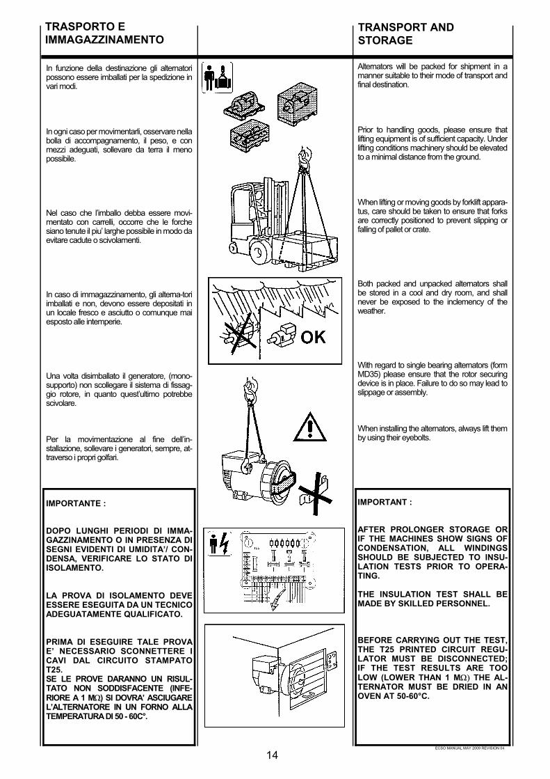
In funzione della destinazione gli alternatoripossono essere imballati per la spedizione invari modi.
In ogni caso per movimentarli, osservare nellabolla di accompagnamento, il peso, e conmezzi adeguati, sollevare da terra il menopossibile.
Nel caso che l’imballo debba essere movi-mentato con carrelli, occorre che le forchesiano tenute il piu’ larghe possibile in modo daevitare cadute o scivolamenti.
In caso di immagazzinamento, gli alterna-toriimballati e non, devono essere depositati inun locale fresco e asciutto o comunque maiesposto alle intemperie.
Una volta disimballato il generatore, (mono-supporto) non scollegare il sistema di fissag-gio rotore, in quanto quest’ultimo potrebbescivolare.
Per la movimentazione al fine dell’in-stallazione, sollevare i generatori, sempre, at-traverso i propri golfari.
IMPORTANTE :
DOPO LUNGHI PERIODI DI IMMA-GAZZINAMENTO O IN PRESENZA DISEGNI EVIDENTI DI UMIDITA’/ CON-DENSA, VERIFICARE LO STATO DIISOLAMENTO.
LA PROVA DI ISOLAMENTO DEVEESSERE ESEGUITA DA UN TECNICOADEGUATAMENTE QUALIFICATO.
PRIMA DI ESEGUIRE TALE PROVAE’ NECESSARIO SCONNETTERE ICAVI DAL CIRCUITO STAMPATOT25.SE LE PROVE DARANNO UN RISUL-TATO NON SODDISFACENTE (INFE-RIORE A 1 MΩ) SI DOVRA’ ASCIUGAREL’ALTERNATORE IN UN FORNO ALLATEMPERATURA DI 50 - 60C°.
TRASPORTO EIMMAGAZZINAMENTO
14
Alternators will be packed for shipment in amanner suitable to their mode of transport andfinal destination.
Prior to handling goods, please ensure thatlifting equipment is of sufficient capacity. Underlifting conditions machinery should be elevatedto a minimal distance from the ground.
When lifting or moving goods by forklift appara-tus, care should be taken to ensure that forksare correctly positioned to prevent slipping orfalling of pallet or crate.
Both packed and unpacked alternators shallbe stored in a cool and dry room, and shallnever be exposed to the inclemency of theweather.
With regard to single bearing alternators (formMD35) please ensure that the rotor securingdevice is in place. Failure to do so may lead toslippage or assembly.
When installing the alternators, always lift themby using their eyebolts.
IMPORTANT :
AFTER PROLONGER STORAGE ORIF THE MACHINES SHOW SIGNS OFCONDENSATION, ALL WINDINGSSHOULD BE SUBJECTED TO INSU-LATION TESTS PRIOR TO OPERA-TING.
THE INSULATION TEST SHALL BEMADE BY SKILLED PERSONNEL.
BEFORE CARRYING OUT THE TEST,THE T25 PRINTED CIRCUIT REGU-LATOR MUST BE DISCONNECTED;IF THE TEST RESULTS ARE TOOLOW (LOWER THAN 1 MΩ) THE AL-TERNATOR MUST BE DRIED IN ANOVEN AT 50-60°C.
TRANSPORT ANDSTORAGE

ECSO MANUAL MAY 2009 REVISION 04
En fonction de la destination des alterna-teurs, ils peuvent être emballés pour l’expédi-tion de différentes manières.
En cas de déplacement des caisses, il estnécessaire de contrôler sur le bordereau delivraison le poids et, avec du materiél adé-quat les soulever de terre le moins hautpossible.
Dans le cas ou l’emballage devra être dé-placé avec des chariots élévateurs, il estnécessaire que les sangles soient tenues leplus large possible de façon à éviter deschutes ou des glissements.
En cas de stockage, les alternateurs embal-lés ou non, doivent être déposés dans unlocal frais et aéré et jamais exposés auxintempéries.
Une fois l’alternateur sortie de l’emballage,(monopalier) ne pas enlever le système defixation du rotor, car dans ce cas, ce dernierpourrait glisser.
Pour les manutentions à la fin de l’installa-tion, soulever les alternateurs, toujours avecleurs propres anneaux de levage.
IMPORTANT :
APRÈS DE LONGUES PÉRIODESDE STOCKAGE OU EN PRÉSENCEDE SIGNES ÉVIDENTS D’HUMIDITÉ/CONDENSATION, VÉRIFIER L’É-TAT D’ISOLEMENT.
L’ESSAI D’ISOLEMENT DOIT ÊTREÉXECUTÉ PAR UN TECHNICIENQUALIFIÉ.
AVANT DE PROCÉDER À UN TELESSAI, IL EST NÉCESSAIRE DE DÉ-CONNECTER LES CABLES DU CIR-CUIT IMPRIME T25; SI LES VA-LEURS MESURÉES SONT INFÈ-RIEURES À CELLES REQUISES(INFÈRIEUR À 1 MΩ) IL EST NÉCES-SAIRE DE SUPPRIMER L’HUMIDITÉEN METTANT L’ALTERNATEURDANS UN FOUR À 50-60°C.
In Abhängigkeit von dem Zielort, können dieGeneratoren entsprechend auf verschiedeneArt und Weise für den Versand verpackt wer-den.
In jedem Fall sind für den Transport die Anga-ben des begleitenden Lieferscheins bezüglichGewicht zu beachten; der Generator soll mitgeeigneter Hilfsmittel so wenig wie möglichvom Boden hochgehoben werden.
Sollte die Verpackung mit dem Generator mitGabelstaplern bewegt werden müssen, ist eserforderilch, die Gabelstellung so weit wie mö-glich einzustellen, umdadurch zu verhindern,daß die Verpackung herunterfallen oder herun-terrutschen kann.
Die Lagerung von verpackten und unverpack-ten Generatoren muß in einem kühlen undtrockenen Raum erfolgen, der keinesfalls Wit-tarungseinflüssen ausgesetz ist.
Sobald der Generator (1 Lager Schild) ausseiner Verpackung entnommen ist, darf dieSicherungsvorrichtung für den Rotor nicht ent-ferntwerden, da dieser abrutschen könnte.
Zum Trasport der Generatoren für installa-tionszwecke, dürfen diese stets ausschließlichan ihren dafür vorgesehenen Ringschraubenaufgehängt werden.
WICHTIG :
NACH EINER LÄNGEREN LAGE-RUNGSZEIT ODER BEI DEUTLICHENANZEICHEN VON FEUCHTIGKEITODER KONDENSAT, IST DER ZU-STAND DER ISOLIERUNGEN ZUÜBERPRÜFEN.
DIE ÜBERPRÜFUNG DER ISO-LIERUNG DARF NUR VON EINEM FA-CHMANN DURCHGEFÜHRT WER-DEN.
VOR DER DURCHFÜHRUNG EINERSOLCHEN PRÜFUNG IST ES ERFOR-DERLICH, DIE KARTE T25 ABZU-TRENNEN; SOLLTE DIE ÜBER-PRÜFUNG EIN ZU NIEDRIGES ER-GEBNIS ERBRINGEN, (UNTERHALBVON 1 MΩ), MUß DER GENERATOR INEINEM OFEN BEI 50-60°C GETROCK-NET WERDEN.
En función del destino final, los alternadorespodrán ser embalados para su expedición envarios modos.
En todos los casos, para moverlos, observaren la factura, el peso y con los medios ade-cuados, elevarlos del piso lo menos posible.
En caso que el embalaje sea movido pormedio de un elevador, será necesario quelas cuerdas del mismo ocupen todo la basede la caja, para evitar caídas o deslizamien-tos.
En caso de depósito, los alternadores con osin embalaje, deberán ser puestos en unlugar fresco y seco o por lo menos nunca serexpuestos a la intemperie.
Una vez desembalado el generador,(Monosoporte) no quitar el sistema de fija-ción del rotor, pues de otra manera el mismopodría deslizarse y caer.
Para mover los generadores antes de suinstalación, elevarlos siempre por medio desus ganchos respectivos.
IMPORTANTE :
DESPUES DE LARGOS PERIODOSDE DEPOSITO O EN PRESENCIA DEEVIDENTES SIGNOS DE HUMEDADO CONDENSACION, CONTROLAREL ESTADO DE AISLACION.
LA PRUEBA DE AISLACION DEBESER EFECTUADA POR UN TECNICOADECUADAMENTE CALIFICADO.
ANTES DE REALIZAR LA PRUEBAES NECESARIO DESCONECTARLOS CABLES DEL CIRCUITO IM-PRESO T25; SI LOS RESULTADOSSON DEMASIADO BAJOS (INFE-RIOR A 1MΩ), SE DEBERA SECAREL ALTERNADOR EN UN HORNO A50-60 °C.
15
TRANSPORT ETSTOCKAGE
TRANSPORT UNDLAGERUNG
TRANSPORTE YDEPOSITO
ECSO MANUAL MAY 2009 REVISION 04
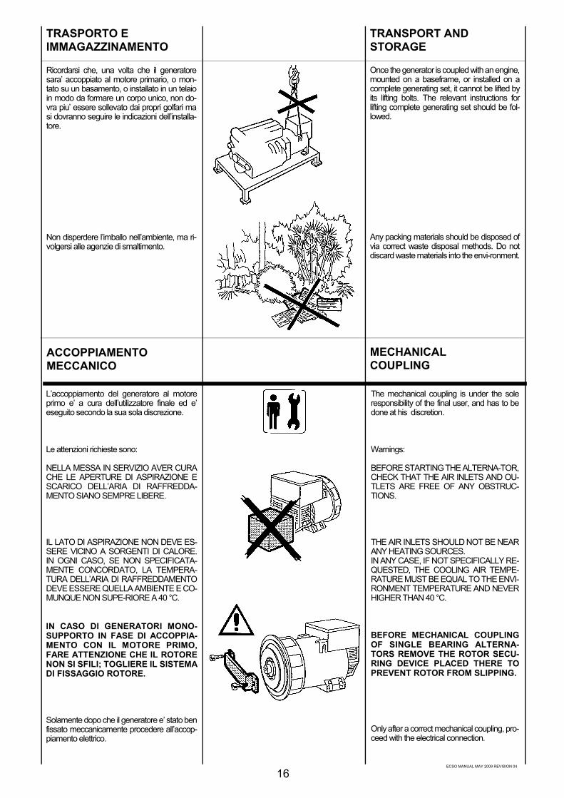
Ricordarsi che, una volta che il generatoresara’ accoppiato al motore primario, o mon-tato su un basamento, o installato in un telaioin modo da formare un corpo unico, non do-vra piu’ essere sollevato dai propri golfari masi dovranno seguire le indicazioni dell’installa-tore.
Non disperdere l’imballo nell’ambiente, ma ri-volgersi alle agenzie di smaltimento.
TRASPORTO EIMMAGAZZINAMENTO
ACCOPPIAMENTOMECCANICO
L’accoppiamento del generatore al motoreprimo e’ a cura dell’utilizzatore finale ed e’eseguito secondo la sua sola discrezione.
Le attenzioni richieste sono:
NELLA MESSA IN SERVIZIO AVER CURACHE LE APERTURE DI ASPIRAZIONE ESCARICO DELL’ARIA DI RAFFREDDA-MENTO SIANO SEMPRE LIBERE.
IL LATO DI ASPIRAZIONE NON DEVE ES-SERE VICINO A SORGENTI DI CALORE.IN OGNI CASO, SE NON SPECIFICATA-MENTE CONCORDATO, LA TEMPERA-TURA DELL’ARIA DI RAFFREDDAMENTODEVE ESSERE QUELLA AMBIENTE E CO-MUNQUE NON SUPE-RIORE A 40 °C.
IN CASO DI GENERATORI MONO-SUPPORTO IN FASE DI ACCOPPIA-MENTO CON IL MOTORE PRIMO,FARE ATTENZIONE CHE IL ROTORENON SI SFILI; TOGLIERE IL SISTEMADI FISSAGGIO ROTORE.
Solamente dopo che il generatore e’ stato benfissato meccanicamente procedere all’accop-piamento elettrico.
16
Once the generator is coupled with an engine,mounted on a baseframe, or installed on acomplete generating set, it cannot be lifted byits lifting bolts. The relevant instructions forlifting complete generating set should be fol-lowed.
Any packing materials should be disposed ofvia correct waste disposal methods. Do notdiscard waste materials into the envi-ronment.
The mechanical coupling is under the soleresponsibility of the final user, and has to bedone at his discretion.
Warnings:
BEFORE STARTING THE ALTERNA-TOR,CHECK THAT THE AIR INLETS AND OU-TLETS ARE FREE OF ANY OBSTRUC-TIONS.
THE AIR INLETS SHOULD NOT BE NEARANY HEATING SOURCES.IN ANY CASE, IF NOT SPECIFICALLY RE-QUESTED, THE COOLING AIR TEMPE-RATURE MUST BE EQUAL TO THE ENVI-RONMENT TEMPERATURE AND NEVERHIGHER THAN 40 °C.
BEFORE MECHANICAL COUPLINGOF SINGLE BEARING ALTERNA-TORS REMOVE THE ROTOR SECU-RING DEVICE PLACED THERE TOPREVENT ROTOR FROM SLIPPING.
Only after a correct mechanical coupling, pro-ceed with the electrical connection.
TRANSPORT ANDSTORAGE
MECHANICALCOUPLING

ECSO MANUAL MAY 2009 REVISION 04
17
Se rappeler qu’une fois l’alternateur accoupléau moteur d’entraînement, ou monté sur socle,ou installé sur un châssis de manière à formerun seul bloc, il ne devra plus être soulevé parses propres anneaux de levage mais il faudrasuivre les indications de l’installateur.
Ne pas jeter l’emballage dans la nature maiss’adresser à un centre de recyclage.
Sobald der Generator eineal an einen An-triebsmotor angeschlossen wird, bzw. aufeinem Unterbau montiert oder in einem Ra-hmen installiert wird, so daß ein einzigerBlock entsteht, darf er nicht mehr an denRingschrauben angehoben werden.Es sind die Vorschriften des Monteurs zubeachten.
Die Verpackung ist durch die entsprechenden Entsorgungsunternehmen zu entsor-gen.
Recordar que, una vez que el generador seráacoplado al motor primario, o montado en subase, o instalado en una estructura de ma-nera de formar un cuerpo único, no deberáser elevado por medio de sus ganchos, sinoque se deberán seguir las indicaciones delinstalador.
No dejar que el embalaje se pierda en elambiente, dirigirse siempre a cualquier agen-cia que trate el reciclaje de residuos.
L’accouplement de l’alternateur au moteurd’entraînement est à la charge de l’utilisateurfinal et est exécuté selon sa propre méthode.
Les précautions requises sont :
DANS LA MISE EN SERVICE, S’ASSURERQUE LES OUVERTURES D’ASPIRATIONSET L’ EVACUATION DE L’AIR DE REFROI-DISSEMENT SOIENT TOUJOURS LIBRES.
LE CÔTÉ DE L’ASPIRATION NE DOIT PASÊTRE PRÈS D’UNE SOURCE DE CHA-LEUR. DANS CHAQUE CAS, S’IL N’Y A PASDE SPÉCIFICATION PARTICULIÈRE, LATEMPÉRATURE DE L’AIR DE REFROIDIS-SEMENT DOIT ÊTRE CELLE AMBIANTE ETDE TOUTE FAÇON, NE DOIT PAS ÊTRESUPÈRIEURE À 40°C.
DANS LE CAS DES ALTERNATEURSMONOPALIER EN PHASE D’ACCOU-PLEMENT AVEC LE MOTEUR D’EN-TRAÎNEMENT, FAIRE ATTENTIONQUE LE ROTOR N’AIT PAS GLISSÉSUR SON AXE. OTER LE SYSTÈMEDE FIXATION DU ROTOR.
Seulement après que l’alternateur soit bien fixémécaniquement, procéder au raccorde-mentélectrique.
El acoplamiento del generador al motor pri-mario es responsabilidad del usuario final, y elmismo será efectuado a propia discreción.
Los puntos de atención requeridos son :
EN LA PUESTA EN SERVICIO ASEGU-RARSE QUE LAS ABERTURAS DE ASPI-RACION Y DESCARGA DEL AIRE DE RE-FRIGERACION SE ENCUENTREN SIEM-PRE LIBRES DE OBSTACULOS.
EL LADO DE ASPIRACION NO DEBEESTAR CERCA A FUENTES DE CALOR.DE CUALQUIER MANERA, SI NO ES PRE-VIAMENTE CONVENIDO, LA TEM-PERATURA DEL AIRE DE RIFREGE-RACION DEBE SER AQUELLA DEL AM-BIENTE, DE TODOS MODOS NO SUPE-RIOR A 40 °C.
EN CASO DE GENERADOR MONO-SOPORTE EN FASE DE ACOPLA-MIENTO CON EL MOTOR PRIMARIO,ASEGURARSE QUE EL ROTOR NOSE DESLIZE; QUITAR EL SISTEMADE FIJACION DEL MISMO.
Solo después que el generador haya sidoconvenientemente fijado mecánicamente,efectuar la conexión eléctrica.
Der Anschluß des Generatores an einen An-triebsmotor obliegt dem Anwender und er-folgt nach eigenen Ermessen.
Folgende Punkte sind zu beachten :
BEI DER INBETRIEBNAHME IST ZUGEWÄHRLEISTEN, DAß DIE ÖFF-NUNGEN FÜR DIE ANSAUGUNG BZW.FÜR DEN AUSTRITT DER KÜHLLUFT IM-MER FREI BLEIBEN.
DIE ANSAUGSEITE DARF SICH NICHT INDER NÄHE VON WÄRMEQUELLEN BE-FINDEN. FALLS NICHT ANDER-WEITIGVEREINBART, MUß DIE KÜHLLUFTRAUMTEMPERATURE AUF-WEISENUND DARF DEN WERT VON 40°C NICHTÜBERSCHREITEN.
BEI EIN LAGER SCHILD GENERA-TOREN IST IN DER PHASE DES AN-SCHLUSSES AN DEN ANTRIEBSMO-TOR DARAUF ZU ACHTEN, DAßSICH DER ROTOR NICHT LÖST;EINE VORHANDENE BEFESTIGUN-GSSICHERUNG DES ROTORS ISTZU ENTFERNEN.
Erst wenn der Generator mechanisch richtigbefestigt ist, kann mit dem elektrischen An-scluß fortgefahren werden.
TRANSPORT ETSTOCKAGE
TRANSPORT UNDLAGERUNG
TRANSPORTE YDEPOSITO
ACCOUPLEMENTMECANIQUE
MECHANISCHERANSCHLUß
ACOPLAMIENTOMECANICO

ECSO MANUAL MAY 2009 REVISION 04
ISTRUZIONI PER MONTAGGIO ECSO28 IN FORMA COSTRUTTIVA MD35.
Per l’accoppiamento del generatoreECSO28 con forma costruttiva MD35,procedere come segue:
a) attraverso una delle due aperturelaterali e ruotando manualmente il ro-tore, individuare sul mozzo della ven-tola, la relativa vite di bloccaggio
b) rendere la ventola libera di ruotareallentando la vite M8 di bloccaggio,utilizzando una chiave esagonale possi-bilmente con testa snodata
c) posizionare uno dei fori dei dischi inprossimita’ della parte alta di una delleaperture laterali e posizionare lo scaricorealizzato su una delle pale della ven-tola, nella stessa posizione.
d) avvicinare l’alternatore al motore diaccoppiamento
e) allineare uno dei fori di fissaggio deidischi del volano con il foro dei dischiprecedentemente posizionato (punto“c”)
ACCOPPIAMENTOMECCANICO
18
MECHANICALCOUPLING
INSTRUCTIONS FOR THE ASSEM-BLING OF ECSO 28 GENERATORSWITH MD35 FORM.
For the coupling of an ECSO 28 gene-rator with MD35 form, proceed as fol-lows:
a) through one of the two lateral ope-nings, and by manually rotating the ro-tor, detect the relevant clamp screw onthe fan hub
b) let the fan be free to rotate by slacke-ning the M8 screw by means of anhexagonal wrench, possibly having anarticulated head
c) position one of the disk holes nearthe upper part of one of the side ope-nings and place the slit that is on one ofthe fan blades, in the same position.
d) move the generator close to thecoupling engine
e) align one of the flywheel disk faste-ning holes with the holes of the previou-sly positioned disks (point c)

ECSO MANUAL MAY 2009 REVISION 04
ACCOUPLEMENTMECANIQUE
MECHANISCHERANSCHLUß
ACOPLAMIENTOMECANICO
INSTRUCTIONS POUR LE MONTA-GE ECSO 28 SOUS LA FORME MD35.
Pour le couplage du générateurECSO28 sous la forme MD35, procéderainsi:
a) à travers une des deux ouvertureslatérales et en tournant manuellementle rotor, repérer la vis de blocage corre-spondante sur le moyeu du ventilateur
b) faire en sorte que l’hélice puissetourner en dévissant la vis M8 de blo-cage en utilisant une clé hexagonale, sipossible avec tête à joint
c) placer un des trous des disques àproximité de la partie haute d’une desouvertures latérales et placer le déle-stage réalisé sur une des pales duventilateur, dans la même position.
d) approcher l'alternateur au moteur decouplage
e) aligner un des trous de fixation desdisques du volant avec le trou des di-sques placé précédemment (point "c").
MONTAGEANWEISUNGEN FÜRECSO 28 IN BAUFORM MD35.
Zur Koppelung des ECSO 28-Generators mit Bauform MD35 ist wiefolgt vorzugehen:
a) Durch eine der zwei seitlichen Öff-nungen und durch manuelles Drehendes Rotors ist die entsprechendeBlockierschraube auf der Gebläsenabezu erkennen
b) Das Gebläse zum freien Drehen brin-gen, indem man die BlockierschraubeM8 mit einem entsprechenden se-chseckigen, möglichst gelenkigenSchlüssel lockert
c) Eines der zwei Scheibenlôcher inNÄhe der höheren Seite einer der seitli-chen Öffnungen in Stellung bringen.Dabei ist der Abfluss, der sich auf ei-nem der Gebläseflügel befindet, in glei-cher Position zu bringen.
d) Den Wechselstromgenerator demKoppelungsmotor annähern
e) Eines der zwei Befestigungslöcherder Schwungradscheiben mit demvorher eingestellten Scheibenloch an-gleichen (Punkt "c").
INSTRUCCIONES PARA MONTAJEECSO 28 EN FORMA COSTRUTIVAMD35.
Para el acoplaje del generadorECSO28 con forma costrutiva MD35,proceder como sigue:
a) a través de una de las dos aberturaslaterales y girando manualmente el ro-tor, individualizar en la placa del ventila-dor, el correspondiente tornillo de blo-queo
b) liberar el ventilador soltando el tornilloM8 de bloqueo, utilizando una llave hexa-gonal posiblemente con cabeza desatada
c) posicionar uno de los agujeros de losdiscos próximos a la parte alta de una delas aperturas laterales y posicionar la de-scarga realizada en una de las palas delventilador, en la misma posición.
d) aproximar el alternador del motor deacoplaje
e) alinear uno de los agujeros de fijaciónde los discos del volante con el agujerode los discos antes posicionado (punto"c").
19

ECSO MANUAL MAY 2009 REVISION 04
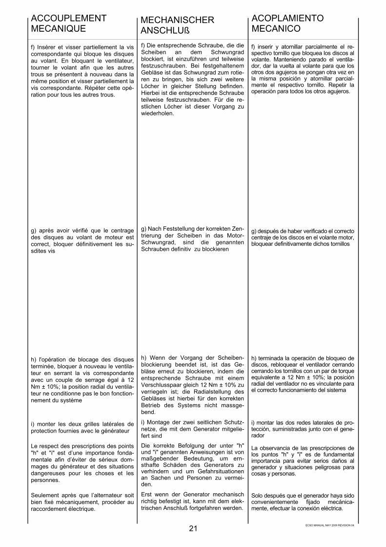
f) inserire ed avvitare parzialmente larelativa vite che blocca i dischi al vo-lano. Tenendo ferma la ventola, ruotareil volano affinchè altri due fori si ripre-sentino nella stessa posizione ed avvi-tare parzialmente la relativa vite. Ripe-tere detta operazione per tutti gli altrifori.
g) dopo aver verificato il corretto cen-traggio dei dischi nel volano motore,bloccare definitivamente dette viti
h) terminata l’operazione di bloccaggiodischi, ribloccare la ventola serrando larelativa vite con una coppia di serraggiopari a 12 Nm ± 10%; la posizione ra-diale della ventola non è vincolante peril corretto funzionamento del sistema
i) montare le due retine laterali di prote-zione, fornite a corredo del generatore.
L’osservanza delle prescrizioni dei punti“h ed “i” è di fondamentale importanzaonde evitare seri danni del generatore esituazioni pericolose per cose e per-sone.
Solamente dopo che il generatore e’stato ben fissato meccanicamente pro-cedere all’accoppiamento elettrico.
ACCOPPIAMENTOMECCANICO
20
MECHANICALCOUPLING
f) Insert and partially tighten the screwsthat lock the disks to the flywheel. Kee-ping the fan still, turn the flywheel untilanother two holes are in the same posi-tion and partially tighten the screw. Re-peat this operation for all the other ho-les.
g) after inspecting the correct centringof the disks on the engine flywheel, thescrews must be completely tightened
h) once the clamping of the disks isover, stop the fan once again by tighte-ning the screw with a torque wrenchsetting adjusted at 12 Nm ± 10%; theradial position of the fan is not bindingfor the correct operation of the system
i) fix the two lateral protection gridssupplied with the generator
Compliance with items "h" and "i" is ofthe utmost consequence in order toavoid serious damages to the generatoror hazardous situations for people orobjects.
Only after a correct mechanical cou-pling, proceed with the electrical con-nections.
ECSO MANUAL MAY 2009 REVISION 04
ACCOUPLEMENTMECANIQUE
MECHANISCHERANSCHLUß
ACOPLAMIENTOMECANICO
f) Insérer et visser partiellement la viscorrespondante qui bloque les disquesau volant. En bloquant le ventilateur,tourner le volant afin que les autrestrous se présentent à nouveau dans lamême position et visser partiellement lavis correspondante. Répéter cette opé-ration pour tous les autres trous.
g) après avoir vérifié que le centragedes disques au volant de moteur estcorrect, bloquer définitivement les su-sdites vis
h) l'opération de blocage des disquesterminée, bloquer à nouveau le ventila-teur en serrant la vis correspondanteavec un couple de serrage égal à 12Nm ± 10%; la position radial du ventila-teur ne conditionne pas le bon fonction-nement du système
i) monter les deux grilles latérales deprotection fournies avec le générateur
Le respect des prescriptions des points"h" et "i" est d’une importance fonda-mentale afin d’éviter de sérieux dom-mages du générateur et des situationsdangereuses pour les choses et lespersonnes.
Seulement après que l’alternateur soitbien fixé mécaniquement, procéder auraccordement électrique.
f) Die entsprechende Schraube, die dieScheiben an dem Schwungradblockiert, ist einzuführen und teilweisefestzuschrauben. Bei festgehaltenemGebläse ist das Schwungrad zum rotie-ren zu bringen, bis sich zwei weitereLöcher in gleicher Stellung befinden.Hierbei ist die entsprechende Schraubeteilweise festzuschrauben. Für die re-stlichen Löcher ist dieser Vorgang zuwiederholen.
g) Nach Feststellung der korrekten Zen-trierung der Scheiben in das Motor-Schwungrad, sind die genanntenSchrauben definitiv zu blockieren
h) Wenn der Vorgang der Scheiben-blockierung beendet ist, ist das Ge-bläse erneut zu blockieren, indem dieentsprechende Schraube mit einemVerschlusspaar gleich 12 Nm ± 10% zuverriegeln ist; die Radialstellung desGebläses ist hierbei für den korrektenBetrieb des Systems nicht massge-bend.
i) Montage der zwei seitlichen Schutz-netze, die mit dem Generator mitgelie-fert sind
Die korrekte Befolgung der unter "h"und "i" genannten Anweisungen ist vonmaßgebender Bedeutung, um ern-sthafte Schäden des Generators zuverhindern und um Gefahrsituationenan Sachen und Personen zu vermei-den.
Erst wenn der Generator mechanischrichtig befestigt ist, kann mit dem elek-trischen Anschluß fortgefahren werden.
f) inserir y atornillar parcialmente el re-spectivo tornillo que bloquea los discos alvolante. Manteniendo parado el ventila-dor, dar la vuelta al volante para que losotros dos agujeros se pongan otra vez enla misma posición y atornillar parcial-mente el respectivo tornillo. Repetir laoperación para todos los otros agujeros.
g) después de haber verificado el correctocentraje de los discos en el volante motor,bloquear definitivamente dichos tornillos
h) terminada la operación de bloqueo dediscos, rebloquear el ventilador cerrandocerrando los tornillos con un par de torqueequivalente a 12 Nm ± 10%; la posiciónradial del ventilador no es vinculante parael correcto funcionamiento del sistema
i) montar las dos redes laterales de pro-tección, suministradas junto con el gene-rador
La observancia de las prescripciones delos puntos "h" y "i" es de fundamentalimportancia para evitar serios daños algenerador y situaciones peligrosas paracosas y personas.
Solo después que el generador haya sidoconvenientemente fijado mecánica-mente, efectuar la conexión eléctrica.
21

ECSO MANUAL MAY 2009 REVISION 04
ACCOPPIAMENTOELETTRICO
L’accoppiamento elettrico e’ a cura dell’utiliz-zatore finale ed e’ eseguito secondo la suasola discrezione.Per l’ingresso nella scatola morsetti si racco-manda di utilizzare passacavi e serracavi inaccordo con le specifiche del paese di espor-tazione.
COLLEGAMENTO AVVOLGIMENTI(tav. 2 pag. 41) .Sono previsti entrambi i collegamenti, stellacon neutro (Y) e triangolo (∆) in tutti gli alterna-tori.Per passare da un collegamento Y a ∆ (es. da400V a 230V) e’ sufficiente spostare i pontisulla morsettiera principale (vedere schematav. 2 pag. 41)Nessun intervento e’ richiesto nel sistema diregolazione.I generatori sono costruiti di serie con 12 cavidi uscita per consentire di ottenere tensionidiverse (es.115 / 200 / 230 / 400V ).I generatori, vanno sempre collegati a terracon un conduttore di adeguata sezione utiliz-zando uno dei due (interno/esterno) appositimorsetti.Dopo aver eseguito il collegamento rimontareil coperchio scatola morsetti.
VERSATILITA’ DI FUNZIONAMENTO50 - 60 HzLa serie ECSO puo’ funzionare indifferente-mente sia a 50 che a 60Hz.Nel generatore ECSO con regolazione solocompound, la tensione generata varia con ilvariare della velocita’. Puo’ essere necessarioche si debba riaggiustare la tensione nel pas-saggio da una frequenza all’altra: a tale propo-sito vedere paragrafo “Regolazione della ten-sione”.
Nel generatore ECSO con AVIR si devonocortocircuitare i previsti terminali per il funzio-namento a 60Hz, come illustrato alla tav. 4pag. 42.La regolazione della tensione si ottieneagendo sul potenziometro “Tensione” comedescritto nel paragrafo “Regolazione della ten-sione”.Passando da 50Hz a 60Hz, la potenza puo’aumentare del 20% (corrente invariata), se latensione aumenta del 20%; se la tensionerimane invariata, la potenza puo’ aumentaredel 5% per effetto della migliore ventilazione.Per generatori costruiti appositamente peruna frequenza di 60Hz nel passaggio a 50Hz,la tensione e la potenza devono necessaria-mente diminuire del 20% rispetto a quelle rife-rite a 60Hz.
REGOLAZIONE DELLA TENSIONE
1) ECSO CON REGOLAZIONESOLO COMPOUND
Regolazione della tensione a vuoto. Per regolare la tensione a vuoto si dovrà agiresull’intraferro del trasformatore (tav. 3 pag. 41)nel seguente modo :
22
All electrical output connections are the respon-sibility of, and are at the discretion of, the enduser.When making terminal box connections, allcable and terminal lugs should meet the rele-vant standards of the country of final destina-tion.
WINDINGS CONNECTION(table 2 pag. 41) .All alternators feature both star with neutral(Y) and delta (∆) connections.To reconnect from a star to delta connection(for ex. from 400V to 230V), modify the linkingarrangements on the output terminal board(see diagram on table 2 page 41).It is not necessary to adjust the voltage regula-tor.Standard alternators are equipped with 12 ca-bles to offer different voltages (ex. 115 / 200 /230 / 400V).The alterrnator must always be earthed by suf-ficiently rated cable, using one of the inside oroutside terminals. After completing output con-nections, ensure that the terminal box cover issecurely in place.
WORKING VERSATILITY 50-60 HzThe ECSO series can work at 50 as wellas at 60 Hz. The ECSO generator withthe only compound regulator varies theoutput voltage by the variation of thespeed. It could be necessary to regulatethe voltage by speed change. To do this,refer to the paragraph "VOLTAGE RE-GULATION".
In the ECSO generator with AVIR theterminals foreseen for the 60 Hz must beshorted, as described in tab. 4 page 42.
The voltage regulation can be operatedthrough the potentiometer marked“Tensione” as described in “Voltage re-gulation” paragraph.
When changing from 50 to 60 Hz thepower can increase by 20% (with nocurrent change), if the voltage increaseby 20%; if the voltage does not change,the power may increase by 5% due toimproved ventilation. For machineswound for 60 Hz, changing to 50 Hz, thevoltage and power values have to decre-ase by 20% of 60 Hz values.
VOLTAGE REGULATION
1) ECSO WITH ONLY COMPOUNDREGULATIONNo-load voltage regulation To regulate the no-load voltage, act onthe air gap of the transformator (table 3page 41) in the following way:
ELECTRICALCONNECTIONS

ECSO MANUAL MAY 2009 REVISION 0423
Le raccordement électrique est à la charge del’utilisateur final et il est exécuté par ses soins.Pour le raccordement à la boite à bornes, il estrecommandé d’utiliser des passe-cables etdes serre cables en accord avec les spécifica-tions du pays d’exportation.
COUPLAGE DES ENROULEMENTS(tab.2 pag. 41).Tous les alternateurs sont prévus pour êtrecouplés soit en étoile avec neutre (Y) soit entriangle (∆).Pour passer de la connexion Y à ∆ (par exem-ple de 400V à 230V) il est suffisant de modifierla position des barettes sur la planchette àbornes (vois schéma Tab. 2 pag. 41).Aucune intervention n’est demandée sur lerégulateur de tension.Les alternateurs sont construits en série de 12fils de sortie afin de permettre d’ obtenir plu-sieurs possibilités de tensions (ex. 115 / 200 /230 / 400V).Les alternateurs doivent toujours être reliés àla terre avec un conducteur de section adé-quat en utilisant une des deux (interne/ex-terne) bornes appropriées.Aprés avoir fait la liaison, remonter le couver-cle de la boite à bornes.
CHANGEMENT DE FONTIONNEMENTDE 50 à 60 HzLes alternateurs de la série ECSO peuventfonctionner indifféremment en 50 ou en 60 Hz.La technologie compound de l’alternateurECSO fait que la tension varie avec la vitesse.De ce fait, il est nécessaire au moment duchangement de la fréquence d’effectuer desmodifications.
Dans l’alternateur ECSO avec AVIR se doi-vent courtcircuiteur les prevus terminales pourle functionnement en 60 Hz, come illustré à latab. 4 pag. 42.
Le réglage de la tension est obtenué en agis-sant sur le potentiomètre “Tension“ commedécrit au paragraphe “Regulation de la ten-sion”.
En passant de 50 Hz à 60 Hz, la puissanceaugmente de 20% (courant constant) si latension augmente de 20%; par contre si latension reste identique, la puissance est aug-mentée de 5% grace à l’augmentation de laventilation.Pour les alternateurs produits à 60 Hz en pas-sant à 50 Hz, la tension et la puissance doi-vent nécessairement diminuer de 20%.
REGULATION DE LA TENSION
1) ECSO AVEC REGULATIONSEULE COMPOUND.Regulation de la tension à vide Pour régler la tension à vide il faut agir sur l’entrefer du trasformateur (tav. 3 pag. 41) de lamanière suivante:
Der elektrische Anschluß obliegt dem En-danwender und erfolgt nach eigenem Ermes-sen.Für den Eingang des Klemmenkastens wirdempfohlen, Kabelführungen und Kabel-schellen zu verwenden, die den Vorschriftenund Spezifikationen des Exportlandes ent-sprechen.
ANSCHLUß WICKLUNGEN(Ab. 2 Seite 41).Für alle Generatoren sind beide Anschlußar-ten vorgesehen: Stern mit Stempunktleiter (Y)und Dreieckschaltung (∆). Um von einer Y-Schaltung auf eine ∆ -Schaltung zu wechseln,(z.B. von 400V auf 230V), ist es ausreichend,die Brücken auf der Hauptklemmleiste zu ver-schieben (siehe Schema Ab.2 Seite 41).Für den Spannungensregler ist keinerlei Ein-griff erforderlich. Bei den Generatoren sindserienmäßig 12 Wicklungsenden auf dasHauptklemmbrett herausgeführt, so daßdurch entsprechendes Umschalten 4 ver-schiedene Spannuhgen möglich sind (z.B.115/200/230/400V). Die Generatoren müs-sen immer mit einem Leiter mit geeignetenQuerschmitt unter Verwendung einer derdafür vorgesehenen Klemmen (innen /außen) geerdet werden.Nach Durchführund des Anschlusses ist dieAbdeckung des Klemmenkastens erneut an-zubringen.
ARBEITSVERSATILITÄT 50-60 HzDie Serie ECSO kann mit 50 sowie mit 60 Hzfunktionieren.Beim Generator ECSO mit nur der Compouddreiphasig Regulierung kann die Spannungmit der Geschwindigkeit ändern.Es kann nötig werden, wenn man die Fre-quenz ändert, die Spannung zu regulieren:Den Abschnitt "SPANNUNG-REGULIERUNG" sehen.
Beim Generator ECSO mit AVIR muß mandie für 60 Hz vorgesehene Armaturen kurz-schließen, wie in Tafel 4 Seite 42 illustriert.
Die Spannungsreglung wird durch den Po-tentiometer "Tensione" erreicht, wie im Ab-schnitt "Spannungsreglung" beschrieben ist.
Beim Übergang von 50 auf 60 Hz darf dieLeistung 20% erhöht werden (selbe Ampere)wenn die Spannung 20% steigert; wenn dieSpannung gleich bleibt darf die Leistung aufGrund einer bessere lüftung 5% steigern.Beim Übergang von 60 auf 50 Hz muussenumgekehrt sowohl die Leistung als auch dieSpannung wieder entsprechend reduziertwerden.
SPANNUNGREGLUNG1) ECSO MIT COMPOUND-REGELUNG
Ladungslose Spannungregulierung Um die Ladungslose Spannung zu regulierenmuß man auf den magnetischen Abstanddes Trasformators handeln (Ab. 3 Seite 41):
La conexión eléctrica es responsabilidad delusuario final y la misma se efectúa a discre-ción de este último.Para la entrada en la caja de bornes se reco-mienda utilizar pasa-cables con su sistema defijación respectivo en conformidad con lasespecificaciones del país de exportación.
CONEXIÓN BOBINADOS(Tab. 2 pag. 41).Se preveen ambas conexiones, estrella conneutro (Y) y triángulo (∆) en todos los alterna-dores.Para pasar de una conexión Y a ∆ (ej. de400V a 230V) es suficiente desplazar lospuentes sobre los bornes principales (veresquema tab. 2 pag. 41).Ningún tipo de intervención es requerido en elregulador de tensión.Los generadores son construidos de serie con12 cables de salida para permitir diferentesvalores de tensión (ej. 115/200/230/ 400V).Los generadores, deben ser siempre conecta-dos a tierra con un conductor de sección ade-quada, utilizando uno de los dos bornes(interno/externo) previstos para la misma.Después de haber realizado la conexión,montar nuevamente la tapa de la caja debornes.
VARIACION DE FRECUENCIA 50-60 HzLa serie ECSO puede funcionar indifferente-mente sea a 50 que a 60 Hz.En el generador ECSO con regulación solocompound, la tensión generada varia con elvariar de la velocidad.Puede ser necesario que se debe rarreglar latension en el paso de una frecuenza el otra: atal pròposito ver el paràgrafo “Regulación de latensión”.En el generadore ECSO con AVIR se debancortocircuito les previstos terminales por el fun-ciònamento a 60 Hz, come illustrado à la tab.4 pag. 42.
La regulaciòn de la tensiòn se consegueagendo sur el potenciòmetro “Tensione” comedescribido en el paràgrafo “Regulaciòn de latensiòn”.
Pasando da 50 a 60 Hz, la potencia puedeaumentar del 20% (corriente invariada), se latensiòn aumenta del 20%, se la tension quedainvariada, la potencia puede aumentar del 5%por efecto de la mejor ventilaciòn.Para generadores construidos a 60 Hz, alpasar a 50 Hz, la tensión y la potencia de-berán disminuir necesariamente un 20% conrespecto a los valores de 60 Hz.
REGULACìON DE LA TENSION1) ECSO CON REGULACION SOLOCOMPOUND
Por ajustar la tensiòn a vaciò Por ajustar la tensión a vaciò se debra rodesur el entrehierro (tav. 3 pag. 41) en el si-guiente modo:
RACCORDEMENTELECTRIQUE
ELEKTRISCHERANSCHLUß
CONEXIONELECTRICA

ECSO MANUAL MAY 2009 REVISION 04
a) regolare la velocita’ del motore a vuoto circa il 4% superiore della velocita’ nominaleb) applicare per un istante un carico non minore del 30% della potenza nominalec) allentare i dadi di serraggio (1)d) aumentare l’intraferro per aumentare la tensione, diminuire l’intraferro per diminuire la tensionee) richiudere bene i dadi di serraggio (1)
Regolazione della tensione a carico Per regolare la tensione a carico si dovra’agire sui ponticelli del circuito stampato T25secondo le posizioni indicate in tav.3 pag. 41.Spostandosi verso la posizione “MAX” la ten-sione aumenta, verso “MIN” la tensione dimi-nuisce.Questa regolazione puo’ leggermente alte-rare anche la tensione a vuoto; se necessa-rio, regolare nuovamente la tensione a vuoto.
2) ECSO CON REGOLAZIONECOUMPOUND + AVIR
Nel generatore ECSO con AVIR la regola-zione della tensione, sia a vuoto che a carico,si ottiene agendo sul potenziometro “TENS.”del regolatore AVIR (tav.4 pag.42).L’AVIR prevede anche una regolazione dellatensione a distanza, inserendo un potenzio-metro da 100 KOhms negli appositi morsettidenominati “POT. ESTER.” come illustrato intav 4 pag. 42.Per fare questo, ridurre la tensione generatacon il potenziometro “TENS.” del regolatore,al 77% del valore nominale, inserire il poten-ziometro esterno e regolare la tensione alvalore desiderato (escursione possibile +6%).Il regolatore AVIR e’ provvisto inoltre di unpotenziometro stabilità “STAB.” (tav.4pag.42) che consente di ottimizzare le presta-zioni del regolatore per ogni alternatore dellaserie ECSO.Nell’AVIR c’e’ anche una protezione di bassavelocita’ che limita l’eccitazione quando talevelocità e’ inferiore del 10% del valore nomi-nale; tale soglia di intervento e’ regolabiletramite il potenziometro “Hz”.
ACCOPPIAMENTOELETTRICO
24
a) regulate the motor speed about 4% more then the nominal speedb) apply for a moment a load not lower than 30% of the nominal powerc) loosen the clamping screws (1)d) increase the air gap to increase the voltage, decrease the gap to lower the voltagee) tighten the clamping screws (1)
Full load voltage regulation To regulate the load voltage act on the bridgesof the T25 printed circuit on the positionsshown on the table 3 page 41.Moving towards the “MAX” position increasesthe voltage, moving towards the “MIN” posi-tion decreases the voltage.This regulation could lightly change the no-load voltage; if necessary, regulate the no-loadvoltage again.
2) ECSO WITH COMPOUND + AVIRREGULATION
With the ECSO provided with AVIR the no-load voltage as well as the load voltage regula-tions are obtained by acting on the "TENS."potentiometer of the AVIR (table 4 page 42).The AVIR is also foreseen for a remote vol-tage regulation, by insertion of a 100 KOhmspotentiometer in the suitable terminals named"POT. ESTER." as illustrated in table 4 page42.To do this, reduce the output voltage using thepotentiometer "TENS." of the regulator, downto 77% of the nominal value, insert the exter-nal potentiometer and regulate the voltage tothe desired value (possible range 6%).The AVIR regulator is also provided with astabilisation potentiometer named "STAB."(table 4 page 42) which allows to optimise theperformances of the regulator for everyECSO series generator.Inside the AVIR is a low speed protection thatlimits the excitation when the speed decrea-ses more then 10% of the nominal value; thisintervention threshold can be regulated by ac-ting on the "Hz" potentiometer.
ELECTRICALCONNECTIONS

ECSO MANUAL MAY 2009 REVISION 04
25
a) régler la vitesse du moteur à vide à environ 4% supèrieure de la vitesse nominaleb) appliquer un instant une charge non moins de 30% de la puissance nominalec) desserer les 3 écrous de serrage (1)d) augmenter l’entrefer pour relever la tension à vide, et diminuer pour reduire la tensione) resserer les écrous de serrage (1)
Regulation de la tension en charge Pour régler la tension en charge, il faut agir surles barettes du circuit imprimé T25 selon lespositions indiquées en tab. 3 pag.41.En déplaçant vers la position “MAX”, la tensionaugmente, vers la position “MIN” la tensiondiminue; ce réglage peut aussi légèrementalterner la tension à vide.
2) ECSO AVEC RÉGLAGE COMPOUND + AVIR
Avec le génerateur ECSO avec AVIR, leréglage de la tension, aussi bien à vide qu’ encharge s’obtient en agissant sur lepotentiomètre “TENS.” du régulateur AVIR.(tab. 4 p. 42).L’ AVIR prévoit également un réglage de latension à distance en inserrant unpotentiomètre de 100 KOhms dans les plotsadéquats dénommes “POT. ESTER.” commeillustré en tab. 4 pag. 42. Pour faire celà,reduire la tension générée avec lePotentiométre “TENS.” dans le regulateur à77% de la valeur nominale, inserrer lepotentiométre externe et régler la tension à lavaleur desirée (plage de reglage +6%).Le regulateur AVIR est en plus pourvu d’ unpotentiométre de stabilité “STAB.” (tab. 4 pag.42) qui sert à optimiser les prestations durégulateur pour chaque alternateur de la serieECSO .Dans l’AVIR il y a aussi une protection debasse vitesse qui limite l’ exitation quand unetelle vitesse est infèrieure aux 10% de la valeurnominale; une telle forme d’intervention n’estrégable que par le potentiométre “Hz”.
a) Die Motorgeschwindigkeit ungefähr 4% höher als die Nominale einstellenb) Eine Ladung mindestens 30% der nominale Ladung für einen Moment anwendenc) Die Mütter (1) lösend) Um die Spannung zu erhöhen muß man den magnetischen Abstand erhöhen, um Ihn zu vermindern muß man den Abstand verminderne) Die Mütter (1) wieder zudrehen
Spannungregulierung unter Ladung Die Ladungspannung wird durch die Brückenauf der elektronische Karte T25 wie auf Tafel3 Seite 41 gezeigt, reguliert.Wenn man auf “MAX” zugeht wird die Span-nung höher, auf “MIN” zu wird die Spannungniedriger; diese Regulierung kann die Ladung-slose Spannung ein wenig austellen, im FallSie wieder einstellen.
2) ECSO MIT COMPOUND + AVIR
Beim ECSO Generator mit AVIR werdenbeide Ladungslose und unter Ladung Span-nungen durch den Potentiometer "TENS."vom AVIR reguliert (Tafel 4 Seite 42).Der AVIR ist auch für entlegene Spannungre-gulierung vorgesehen, mit der einstellung voneinem Potentiometer von 100 KOhms in denversehenen "POT. ESTER." gezeichnete Ar-maturen, wie in Tafel 4 Seite 42 gezeichnet.Um das zu machen, die erziehlte Spannungauf 77% vermindern, den ausseren Potentio-meter einsetzen (Tätigkeitsbereich 6%).Der AVIR Regler hat auch einen Stabilitätpo-tentiometer "STAB." (Tafel 4 Seite 42) der dieLeistungen des Reglers für alle Generatorender ECSO Serie optimisiert.Im AVIR gibt es auch eine Sicherung für nie-drige Geschwindigkeit die die Aufregung be-schränkt wenn Diese mehr als 10% der Nomi-nale Geschwindigkeit niedriger wird; dieseGrenze kann durch den Potentiometer "Hz"eingestellt werden.
a) regular la velocidad del motor a vacìo aprox. el 4% superior de la velocidad nominalb) applicar durante un istante un carga no inferior del 30% de la potencìa nominalc) flojar las tuercas de cerragio (1)d) aumentar el entrehierro por aumentar la tensìón, disminuir el entrehierro por disminuir la tensióne) encerrar bien las tuercas de cerragio (1)
Regulación de la tensiòn a carga Por regular la tensión a carga se tendrà queactuar sobra los puentecillos del enganadoimpreso T25 segundo les posiciòns indicadeen tav. 3 pag. 41.Apartandose verso la posicìon “MAX” la ten-sìon aumenta, verso “MIN” la tensìon diminue;esta regulacìón pueda ligermente alterar tam-bìen la tensìon a vacìo, se necesario, regularnuevamente la tensìón a vacìo.
2)ECSO CON REGULACIÓN COMPOUND+AVIR
En el generador ECSO con AVIR la regula-ción de la tensión, sea a vacìo que a carga,se obtiene agendo sobra el potencìometro“TENS.” de el regulador AVIR (tav. 4 pag. 42).El AVIR preveto tambìen una regulación de latensìón a distancia insertando un potencìome-tro de 100 KOhms en los bornes respectivosllamado “POT. ESTER.” como explicado entav. 4 pag. 42.Por hacer esto reducir la tensìón engendradocon el potencìometro “TENS.” en el reguladoral 77% de el valor nominal, insertar el poten-ciòmetro exsterno y regular la tensión al valordeseato (excursiòn posible +6%).El regulador AVIR es prove ademàs de unpotenciòmetro estable “STAB.” (tav. 4 pag.42) que consente de optimizare les prestatiònde el regulador por cada alternador de la serieECSO.En el AVIR hay tambièn una proteccìon debaja velocidad que limita l’ excitation cuandotal velocidad es inferior de el 10% valor nomi-nal; tal umbral de intervencìon es regulablepassaggio el potenciòmetro “Hz”.
RACCORDEMENTELECTRIQUE
ELEKTRISCHERANSCHLUß
CONEXIONELECTRICA

ECSO MANUAL MAY 2009 REVISION 04
COME INSERIRE O SOSTITUIREIL REGOLATORE AVIRCon riferimento allo schema illustrativo (tav. 4pag. 42) eseguire le seguenti operazioni amacchina ferma :a) aprire la “scatola di regolazione”.Nel caso si debba sostituire il regolatoreAVIR, si dovra’ prima togliere il regolatoreguasto.b) inserire il connettore (1) nella morsettiera del regolatore (2) da montare.c) inserire le viti nella morsettiera (5) del circuito stampato T25.d) inserire il regolatore “AVIR” (2) nell’apposito alloggio infilando il connettore nella morsettiera ( 5) del circuito stampato T25.e) inserire le viti (3) negli appositi fori agli angoli del regolatore “AVIR” (2) e fissare.f) fissare le viti della morsettiera (5) e del regolatore “AVIR” (2).g) inserire il fusibile (4) da 6,3A nell’apposito alloggio sulla scheda T25.L’alternatore puo’ ora funzionare: se neces-sario regolare la tensione e la stabilita’ comeindicato nel paragrafo “regolazione della ten-sione”.
FUNZIONAMENTO IN PARALLELO1) ECSO CON REGOLAZIONE COM-POUND
Nel generatore ECSO senza regolatore elet-tronico AVIR il parallelo e’ possibile per alter-natori dello stesso tipo e preferibilmente diuguale potenza collegando in parallelo con-temporaneamente alle macchine anche icampi delle eccitatrici (morsetti 6 positivo e 7negativo del circuito stampato T25) tramitecavi da 1 mm².
2) ECSO CON AVIRIn questo caso è sufficiente montare il dispo-sitivo di parallelo PD200 ed eseguendo lestesse operazioni del punto 1) è possibile ilparallelo con alternatori oltre che dello stessotipo, anche di tipo diverso e parallelo rete.E’ inoltre possibile il parallelo rete con regola-zione del fattore di potenza inserendo il dispo-sitivo PFR 96/1.
COME ECCITARE L’ALTERNATORELa serie ECSO non dovrebbe presentareproblemi di smagnetizzazione.Se per qualsiasi inconveniente fosse neces-sario rieccitare l’alternatore, attenersi aquanto segue :con l’alternatore funzionante a vuoto alla velo-cita’ nominale inserire per alcuni secondi unabatteria da 12V, tra i morsetti 4 (rosso +) e 5(verde -) del circuito stampato T25 (tav.7-8pag. 44).
Dopo aveseguito tutti i collegamentielettrici e solo dopo aver chiuso tuttele protezioni e’ possibile effettuare laprova di primo avviamento del sistema.
ACCOPPIAMENTOELETTRICO
26
INSERTING O SUBSTITUTING THEAVIR REGULATORReferring to the illustrating scheme (table 4page 42) carry out the following operations bystanding machine:a) open the "regulation box". In case the AVIR regulator must be substituted, the damaged regulator must be removed first.b) insert the connector (1) in the terminal board of the regulator (2) to be mounted.c) insert the screws in the terminal board (5) of the printed circuit T25.d) insert the AVIR regulator (2) in his suitable place, inserting the connector in the terminal board (5) of the printed circuit T25.e) insert the screws (3) in the suitable holes on the edges of the AVIR regulator (2) and tighten.f) tighten the screws of the terminal board (5) and the AVIR regulator (2).g) insert the 6.3A fuse (4) in his suitable place on the printed circuit T25.
The alternator is now ready: if necessary,regulate the voltage and the stability as ex-plained in the paragraph "voltage regula-tion".
WORKING IN PARALLEL1) ECSO WITH COMPOUND REGULATION
ECSO generators without AVIR regulation canwork in parallel if they are all of the same typeand preferably all of same performance, byconnecting in parallel, together with the machi-nes, also the fields of the exciters (terminals 6positive and 7 negative of the printed circuitT25), using 1mm² cables.
2) ECSO WITH AVIRIn this case it is sufficient to mount the paralleldevice PD200 and carry out the same opera-tions as described in point 1, allowing to usealso machines of different type and in mainsparallel.Moreover, inserting the PFR 96/1 can beachieved the mains parallel with power factorregulation.
HOW TO EXCITE THE ALTERNATORThe ECSO series generally do not give dema-gnetisation problems. If it would be necessaryto excite the alternator, act as follows:with the alternator working unloaded at nomi-nal speed, connect for a few seconds a 12Vbattery to the terminals 4 (red +) and 5 (green-) of the printed circuit T25 (table 7-8 page 44).
After all the electric connections havebeen made and only after all the pro-tections have been put in place, canthe system be started.
ELECTRICALCONNECTIONS

ECSO MANUAL MAY 2009 REVISION 04
27
COMMENT INSERER OU REMPLA-CER LE REGULATEUR AVIR.Comme illustré par le schéma, (tab.4p. 42), exécuter les opérations suivantes(ensemble à l’arrêt) :a) ouvrir la” boite de régulation” En cas de substitution du régulateur AVIR, extraire avant tout celui endommagé.b) inserer le connecteur (1) dans le porte-plots du régulateur (2) à monter.c) inserer les vis dans le porte-plots (5) du circuit imprimé T25.d) inserer le régulateur “AVIR” (2) dans le logement adéquat en positionnant le connecteur dans le porte-plots (5) du circuit imprimé T25.e) inserer les vis (3) dans les angles du régulateur “AVIR” (2) et fixer .f) fixer les vis du porte-plots (5) et du régulateur “AVIR” (2).g) mettre le fusible (4) de 6,3 A dans le logement prévu sur la T25.
Vous pouvez alors faire fonctionner l’alter-nateur; si néccessaire, régler la tension et lastabilité comme indiqué dans le paragraphe“régulation de la tension”.
FONCTIONEMMENT ENPARALLELE.1) ECSO AVEC REGULATION COMPOUNDDans l’alternateur ECSO sans régulateurelectronique AVIR, le paralléle est possiblepour des alternateurs du même type et, depréférence de puissance égale, en reliant lesdébits en phase et les excitations (bornes 6positif et 7 négatif du circuit imprimé T25) enutilisant des cables d’1 mm².
2) ECSO AVEC AVIR.Dans ce cas, il est suffisant de monter ledispositif de mise en parallèle PD200 et d'ef-fectuer les mêmes opérations indiquées aupoint 1, permettant ainsi d'utiliser égalementdes alternateurs autres que ceux du mêmetype et en parallèle réseau.De plus, il est possible d'obtenir le parallèleréseau avec régulation du facteur de puis-sance en insérant le dispositif PFR96/1
COMMEMT EXCITER L’ALTERNATEURLa série ECSO ne devrait presenter aucunproblème de démagnétisation.Si pour une quelconque raison, l’alternateurvenait à se désexciter, suivre l’indication sui-vante :l’alternateur fonctionnant à vide, à la vitessenominale, inserer pour quelques secondesune batterie de 12V, entre les bornes 4 (rouge+) et 5 (vert -) du circuit imprimé T25 (tab.7-8p. 44) .
Aprés avoir exécuté tous les raccorde-ments électriques et seulement aprésavoir contrôlé le fonctionnement detoutes les protections, il est possibled’effectuer l’essai de la première miseen marche du système.
COMO INSERTAR O SUSTITUIREL REGULADOR AVIR.Con referencia a lo esquema illustrado,(tav. 4 pag. 42) efectuar les siguientesoperacións a maquina fija:a) abrir la “caja de regulación”. En el caso se debe sostituir el regulador AVIR, se debrà antes de quitar el regulador estopeado.b) insertar el conecto (1) en la borne (5) del regulador (2) desde montar.c) insertar los tornillos en la borne (5) del circuito impreso T25.d) insertar el regulador AVIR (2) en el respectivo alojo ensertando el conecto en la borne (5) y del circuito impreso T25.e) insertar los tornillos (3) en los respectivos ojos a los angulos del regulador “AVIR” (2) y fijar. f) fijar los tornillos de la borne (5) y del regulador “AVIR”(2).g) insertar el fusible (4) desde 6,3 A en el respectivo alojo sobra la ficha T25.
El alternador puedas ahora funcionar; senessario regular la tensión y la establetacomo indicado en el paràgrafo “regulación dela tensión”.
FUNCIONAMENTO EN PARALELO.
1) ECSO CON REGULACION COMPOUNDEn el generador ECSO sin reguladorelectrónico AVIR el paralelo es posible por losalternadores de lo mismo tipo y preferi-blemente de igual potencia conectendo enparalelo contemporàneamente a les màqui-nes tambièn los campos de les excitatriz(bornes 6 positivos y 7 negativo del circuitoimpreso T25) passagio cabos de1 mm².
2) ECSO CON AVIREn esto caso es suficiente montar eldispositivo de paralelo PD200 y efectuandoles mismes operaciònes del punto 1) esposible el paralelo con alternadores màs allàque de lo mismo tipo, tambièn de tipo diversoy paralelo red.Es ademàs possible el paralelo red conregulación de el factor de potencia insertandoel dispositivo PFR 96/1.
COMO EXCITAR EL ALTERNADOR.La serie ECSO no debrìa presentardificultades de desimentar.Se por cualquier inconveniente fue neces-sario autoexcitar el alternador, respetar acuànto sigue.Con el alternador funciònante a vacìo a lavelocidad nominal insertar por alguiensegundos una baterìa de 12V, entre bornes 4(rojo +) y 5 (verde -) del circuito impreso T25.(tav. 7-8 pag.44).
Después de haber realizado todas lasconexiones eléctricas y solo despuésde haber cerrado todas lasprotecciones es posible efectuar elprimer arranque del sistema.
DEN AVIR REGLER EINSETZENODER ERSETZENMit Hilfe der Tafel 4 Seite 42 die folgende Ta-ten it stille Maschine ausführen:a) Die "Regelungskiste" öffnen. Im Fall daß man den AVIR Regler ersetzen muß, ihn erst abnehmen.b) Den Leiter (1) in die Armaturen des Reglers einstecken.c) Die Schrauben in den Armaturen (5) der elektronische Karte T25 einstecken.d) Den AVIR Regler (2) in seinen Sitz und den Leiter in den Armaturen (5) der elektronische Karte T25 einführen.e) Die Schrauben (3) in ihren Löchern an den Ecken des Reglers (2) einstecken und fixieren.f) Die Schrauben der Armaturen (5) und des Reglers (5) zuschrauben.g) Die 6,3A Sicherung in seinem Platz auf der T25 Karte einstecken.
Der Generator kann jetzt funktionnieren: wennes nötig wäre, die Spannung und die Stabilität,wie im Abschnitt "Spannung-sregelung" be-schrieben, einstellen.
BETRIEB IN PARALLEL
1) ECSO MIT COMPOUND
Die Generatoren ECSO ohne AVIR können inParallel montiert werden, wenn sie alle vomselben Typ und vorzugsweise von selbeStärke sind, dann muß man auch die Felderder Aufreger in Parallel mit Kabeln von 1 mm²montieren (Armaturen 6 positiv und 7 negativder elektronische Karte T25).
2) ECSO MIT AVIRIn diesem Fall genügt es, die Vorrichtung fürParallel PD200 zu montieren und wie im Punkt1 vorgehen; das macht den Parallel auch vonverschiedenen Generatoren un den Netz Pa-rallel möglich.Der Netz Parallel mit Potenzfaktorregler wirdmit dem Einsatz der Vorrichtung PFR 96/1möglich.
DEN ALTERNATOR AUFREGENDie Serie ECSO gibt normalerweise keineProbleme von Entmagnetisierung. Wenn esder Fall wäre, folgend vorgehen:Mit dem Generator im Lehrlauf eine 12V Bat-terie für wenigen Sekunden an den Armaturen4 (Rote +) und 5 (Grune -) von der elektroni-sche Karte T25 verbinden (Tafel 7-8 Seite 44).
Nachedem alle elektrischen Anschlüsseansgeführt und nur nachdem alleSchtzvorrichtungen geschlossenwurden, ist es möglich, die Prüfungeines ersten Systemstarts dur-chzuführen.
RACCORDEMENTELECTRIQUE
ELEKTRISCHERANSCHLUß
CONEXIONELECTRICA
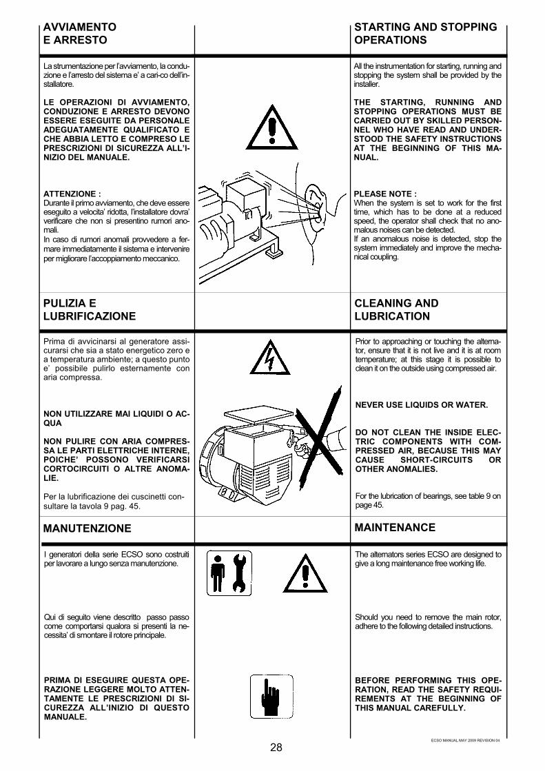
ECSO MANUAL MAY 2009 REVISION 04
La strumentazione per l’avviamento, la condu-zione e l’arresto del sistema e’ a cari-co dell’in-stallatore.
LE OPERAZIONI DI AVVIAMENTO,CONDUZIONE E ARRESTO DEVONOESSERE ESEGUITE DA PERSONALEADEGUATAMENTE QUALIFICATO ECHE ABBIA LETTO E COMPRESO LEPRESCRIZIONI DI SICUREZZA ALL’I-NIZIO DEL MANUALE.
ATTENZIONE :Durante il primo avviamento, che deve essereeseguito a velocita’ ridotta, l’installatore dovra’verificare che non si presentino rumori ano-mali.In caso di rumori anomali provvedere a fer-mare immediatamente il sistema e intervenireper migliorare l’accoppiamento meccanico.
AVVIAMENTOE ARRESTO
PULIZIA ELUBRIFICAZIONE
Prima di avvicinarsi al generatore assi-curarsi che sia a stato energetico zero ea temperatura ambiente; a questo puntoe’ possibile pulirlo esternamente conaria compressa.
NON UTILIZZARE MAI LIQUIDI O AC-QUA
NON PULIRE CON ARIA COMPRES-SA LE PARTI ELETTRICHE INTERNE,POICHE’ POSSONO VERIFICARSICORTOCIRCUITI O ALTRE ANOMA-LIE.
Per la lubrificazione dei cuscinetti con-sultare la tavola 9 pag. 45.
I generatori della serie ECSO sono costruitiper lavorare a lungo senza manutenzione.
Qui di seguito viene descritto passo passocome comportarsi qualora si presenti la ne-cessita’ di smontare il rotore principale.
PRIMA DI ESEGUIRE QUESTA OPE-RAZIONE LEGGERE MOLTO ATTEN-TAMENTE LE PRESCRIZIONI DI SI-CUREZZA ALL’INIZIO DI QUESTOMANUALE.
MANUTENZIONE
28
All the instrumentation for starting, running andstopping the system shall be provided by theinstaller.
THE STARTING, RUNNING ANDSTOPPING OPERATIONS MUST BECARRIED OUT BY SKILLED PERSON-NEL WHO HAVE READ AND UNDER-STOOD THE SAFETY INSTRUCTIONSAT THE BEGINNING OF THIS MA-NUAL.
PLEASE NOTE :When the system is set to work for the firsttime, which has to be done at a reducedspeed, the operator shall check that no ano-malous noises can be detected.If an anomalous noise is detected, stop thesystem immediately and improve the mecha-nical coupling.
Prior to approaching or touching the alterna-tor, ensure that it is not live and it is at roomtemperature; at this stage it is possible toclean it on the outside using compressed air.
NEVER USE LIQUIDS OR WATER.
DO NOT CLEAN THE INSIDE ELEC-TRIC COMPONENTS WITH COM-PRESSED AIR, BECAUSE THIS MAYCAUSE SHORT-CIRCUITS OROTHER ANOMALIES.
For the lubrication of bearings, see table 9 onpage 45.
The alternators series ECSO are designed togive a long maintenance free working life.
Should you need to remove the main rotor,adhere to the following detailed instructions.
BEFORE PERFORMING THIS OPE-RATION, READ THE SAFETY REQUI-REMENTS AT THE BEGINNING OFTHIS MANUAL CAREFULLY.
STARTING AND STOPPINGOPERATIONS
CLEANING ANDLUBRICATION
MAINTENANCE
ECSO MANUAL MAY 2009 REVISION 04
29
La manipulation pour le démarrage, le fonc-tionnement et l’arrêt est à la charge de l’instal-lateur.
LES OPERATIONS DE DEMAR-RAGE, FONCTIONEMENT ET ARRETDOIVENT ETRE FAITES PAR DUPERSONNEL QUALIFIE AYANT LUET COMPRIS LES PRESCRIPTIONSDE SECURITE AU DEBUT DU MA-NUEL.
ATTENTION :Durant le premier démarrage, qui doit êtreexécuté à vitesse réduite, l’installateur doit vé-rifier qu’aucun bruit anormal ne se présente.Dans le cas de bruits anormaux, interrompreimmédiatement le fonctionnement et vérifierl’accouplement mécanique.
Die Instrumentierung für Antrieb, dieNetzführung und die Stillsetzung der Systemeobliegt dem Monteur.
ANTRIEB, NETZFÜHRUNG UND STIL-LSETZUNG DÜRFEN AUS-SCHLIEßLICH VON ENTSPRECHENDQUALIFIZIERTEN FACHPERSONALDURCHGEFÜHRT WERDEN UNDZWAR ERST NACHDEM DIE SI-CHERHEITSVORSCHRIFTEN AM AN-FANG DIESES HANDBUCHS GE-LESEN UND VERSTANDEN WORDENSIND.
ACHTUNG :Während der ersten Inbetriebnahme, die mitreduzierter Geschwindigkeit erfolgen muß, hatder Monteur zu überprüfen, ob Anomalien inder Geräuschentwicklung auftreten. Im Fallevon Anomalien in der Geräuschentwicklung,ist dafür zu sorgen, daß die Anlage unverzü-glich gestoppt wird. Die mechanischen An-schlüsse müssen in diesem Falle verbessertwerden.
La instrumentación para el arranque, la con-ducción y la parada del sistema es a cargo delinstalador.
LAS OPERACIONES DE AR-RANQUE, CONDUCCION Y PARADADEBEN SER REALIZADAS PORPARTE DE PERSONAL ADECUA-DAMENTE CALIFICADO Y QUE HAYALEIDO Y COMPRENDIDO LAS NOR-MAS DE SEGURIDAD AL PRINCIPIODEL MANUAL.
ATENCION :Durante el primer arranque, que deberá efec-tuarse a baja velocidad, el instalador deberácontrolar que no se presenten rumores anor-males.En caso de rumores anormales, detener in-mediatamente el sistema e intervenir paramejorar el acoplamiento mecánico.
Avant tout contact avec l’alternateur, s’assu-rer de sa propreté parfaite et qu’il soit à tem-pérature ambiante; il est alors possible de lenettoyer exterieurement avec de l’air com-primé.
NE JAMAIS UTILISER DE LIQUIDEOU DE L’EAU.
NE PAS NETTOYER AVEC DE L’AIRCOMPRIME LES PARTIES ELECTRI-QUES INTERNES, CAR L’ON POUR-RAIT PROVOQUER UN COURT-CIRCUIT OU AUTRES ANOMALIES.
Pour le graissage des roulements, con-sulterle tableau 9 pag. 45.
Bevor Sie sich dem Generator nähern, ist si-cherzustellen, daß dieser nicht mehrstromführend ist und sich auf Raum-temperatur abgekühlt hat; zu diesem Zeit-punkt ist es möglich, den Generator vonaußen mit Preßluft zu reinigen.
NIEMALS FLÜSSIGREINIGER ODERWASSER VERWENDEN.
DIE INNENLIEGENDEN ELEKTRO-TEILE NIEMALS MIT PRESSLUFTREINIGEN, DA SICH KURZSCHLÜS-SE ODER ANDERE STÖRUNGEN DA-RAUS ERGEBEN KÖNNTEN.
Bezüglich der Schmierung der Lagersind die Angaben in Tabelle 9, Seite 45zu befolgen.
Antes de acercarse al generador, asegurarseque el mismo sea a estado energético cero ya temperatura ambiente; en estas condicio-nes es posible limpiarlo externamente conaire comprimido.
NO UTILIZAR NUNCA LIQUIDOS OAGUA.
NO LIMPIAR CON AIRE COMPRI-MIDO LAS PARTES ELECTRICAS IN-TERNAS, DEBIDO A LA POSIBILI-DAD DE CAUZAR CORTOCIRCUI-TOS O CUALQUIER OTRO TIPO DEPROBLEMA.
Para la lubrificación de los cojinetes consultarla tabla 9 pag. 45.
Les alternateurs de la série ECSO sont con-struits pour fonctionner longtemps sans au-cun entretien.
Ci-après, vous trouverez la marche à suivre sil’on a la nécessité de démonter le rotor princi-pal.
AVANT D’EXECUTER CETTE OPE-RATION, LIRE ATTENTIVEMENT LESPRESCRIPTIONS DE SECURITE AUDEBUT DU MANUEL.
Die Generatoren der Serie ECSO sind so kon-struiert, daß sie einen langen Zeitraum ohneWartung arbeiten können.
Im folgenden wird Schritt für Schritt die Vor-gehensweise beschrieben für den Fall, daßder Hauptrotor demontiert werden muß.
BEVOR DIESE ARBEITEN DURCHGE-FÜHRT WERDEN, SIND DIE AM AN-FANG DIESES HANDBUCHES ANGE-GEBENEN SICHERHEITSVOR-SCHRIFTEN AUFMERKSAM ZU LE-SEN.
Los generadores de las series ECSO sonconstruidos para trabajar por mucho tiemposin mantenimiento.
A continuación se describe paso a paso elmetodo para desmontar el rotor principal.
ANTES DE REALIZAR DICHA OPE-RATION LEER CUIDADOSAMENTELAS NORMAS DE SEGURIDAD ALPRINCIPIO DE ESTE MANUAL.
DEMARRAGEET ARRET
ANTRIEB UNDSTILLSETZUG
ARRANQUE YPARADA
NETTOYAGE ETGRAISSAGE
REINIGUNG UNDSCHMIERUNG
LIMPIEZA YLUBRIFICACION
MANTENIMIENTOWARTUNGMANUTENTION

ECSO MANUAL MAY 2009 REVISION 04
Per smontare l’alternatore della serie 28 - 31 -32 non e’ necessario rimuovere il rotore eccita-trice.
Per quanto riguarda la serie 34 per smontarel’alternatore e’ necessario rimuovere l’ec-citatrice, attenendosi quindi a quanto segue.
Togliere la chiusura posteriore,
sconnettere i cinque fili del ponte diodi rotante“A” e “B”,
togliere le viti di bloccaggio dei settori.
Inserire un adeguato estrattore, facilmente co-struibile o reperibile presso la nostra sede;come illustrato in figura.Tale estrattore consente di togliere l’eccita-tricecon molta rapidita’.
NEL CASO DI SMONTAGGIO DEL RO-TORE PRINCIPALE RICORDARSI DIUSARE UN MEZZO DI SOLLEVA-MENTO CON FUNI MORBIDE MA DIPORTATA ADEGUATA ED ESEGUIREL’ESTRAZIONE MOLTO DELICATA-MENTE.
Per la sostituzione del/i cuscinetto/i utilizzareun estrattore del tipo illustrato in figura.
Per il rimontaggio del cuscinetto, riscaldare lostesso, con un dispositivo magnetico del tipoillustarto in figura.
MANUTENZIONE
30
It is not necessary to extract the excitor rotorfrom the shaft before removing the rotor as-sembly on alternator series 28 - 31 - 32.
As for the series 34, the exciter has to beremoved in order to disassemble the alterna-tor, therefore follow these instruction.
Remove the rear panel,
disconnect the five wires of the rotating diodebridge “A” and “B”,
remove the sectors fixing screws.
Insert a suitable puller, that can be easilymade or supplied by our company, as shownin the picture.This puller will enable to take out the excitervery easily.
WHEN REMOVING THE MAIN RO-TOR, PLEASE REMEMBER TO USE ALIFTING DEVICE EQUIPPED WITHSUITABLE ROPES AND CARRY OUTTHE OPERATION WITH GREATCARE.
To replace the bearing/s, use a puller ofthe type shown in the figure.
To reassemble the bearing, heat it with a spe-cial magnetic device of the type shown in thefigure.
MAINTENANCE

ECSO MANUAL MAY 2009 REVISION 04
Pour démonter l’alternateur de la série 28 - 31- 32, il n’est pas nécessaire d’enlever le rotorde l’ excitatrice.
En ce qui concerne la série 34, pour démon-ter l’alternateur, il est nécessaire d’enlever l’ex-citatrice, et d’opérer comme suit.
Oter la tôle de fermeture,
déconnecter les 5 fils du pont de diodes tour-nant “A” et “B”,
enlever les vies du blocage des zones
Insérer un extracteur adéquat, facilementconstructible comme illustré sur la figure enréférence.Un tel extracteur permet d’ôter l’excitatriceavec beaucoup de rapidité.
DANS LE CAS DU DEMONTAGE DUROTOR PRINCIPAL, UTILISER UNMOYEN DE LEVAGE AVEC DES SAN-GLES SOUPLES MAIS DE DIMEN-SION ADEQUATE ET FAIRE L’EX-TRACTION TRES DELICATEMENT.
Pour le remplacement du/des coussinet/s, uti-liser un extracteur du type illustré sur la figure.
Pour remonter le roulement, réchauffer cedernier avec un dispositif magnétique spécial,du type illustré sur la figure.
Um den Generator der Serie 28 - 31 - 32 zudemontieren, ist es nicht notwendig, den Erre-gerrotor zu entfemen.
Für die Demontage des Generators bezüglichder Serie 34, ist es erforderlich, den Erreger zuentfemen und sich an die nachfolgendenAnweisungen zu halten.
Den hinteren Verschluüß entfemen,
Die fünf Kabel “A” und “B” der rotierendenDiodenbrücke abklemmen,
Durch leichtes Ziehen die Diodenbrücke entfe-men.
Eine geeignete Abziehvorrichtung wie in ne-benstehender Abbildung, ansetzen. Diese Ab-ziehvorrichtung kann leicht selbst angefertigtoder bei uns erhalten werden.Damit kann der Erregerotor rasch herausgezo-gen werden.
WENN DER HAUPTROTOR AUSGE-BAUT WERDEN MUß, IST DAZU EINHEBEWERKZEUG MIT WEICHENSELLEN, DIE EINE GEEIGNETEZUGKRAFT AUFWEISEN, EINZUSET-ZEN. DER AUSBAU HAT MIT GROßERVORSICHT ZU ERFOLGEN.
Für den Austausch des/der Lagers/Lager mußeine wie in der Abbildung dargestellte Ab-ziehvorrichtung verwendet werden.
Für den Wiedereinbau des Lagers ist diesesmit einer Magnetvorrichtung zu erhitzen (sieheAbbildung).
Para desmontar el alternador de la serie 28 -31 - 32 no es necesario quitar el rotor excita-triz.
Para la serie 34, para desmontar el alternadores necesario quitar el rotor excitatriz, por lotanto seguir el procedimiento dado a conti-nuación.
Quitar la tapa posterior,
desconectar los cinco cables del puente dediodos giratorios “A” y “B”,
quitar las vidas del bloqueo de los campos
Introducir un adecuado extractor, fácil de fabri-car o disponible a través de nuestra sede,como se muestra en la figura.Dicho extractor permite de quitar la excitatrizcon mucha rapidez.
PARA EL DESMONTAJE DEL ROTORPRINCIPAL, RECORDAR DE UTILI-ZAR UN MEDIO DE ELEVACION CONCUERDAS FLEXIBLES PERO DE RE-SISTENCIA APROPIADA Y REALIZARLA EXTRACCION EN FORMA DELI-CADA.
Para la sustitución del/de los cojinetes/s utili-zar un extractor, del tipo representado en lafigura.
Para volver a montar el cojinete, calentar esteúltimo por medio de un dispositivo magnéticoadecuado, del tipo representado en la figura.
MANUTENTION WARTUNG MANTENIMIENTO
31

ECSO MANUAL MAY 2009 REVISION 04
Indossare guanti antiscottatura.
Rimontare il/i cuscinetto/i.
Prima di rimontare l’eccitatrice, pulire bene lasede dell’albero e cospargere con un leggerostrato “Permabond AO22” della Angst-Pfister oequivalenti, tale sede.Rimontare seguendo a ritroso le operazioni finqui descritte, facendo attenzione che i cavi dicollegamento diodi siano rivolti verso l’esterno.
Utilizzando un attrezzo simile a quello rappre-sentato in figura, rimontare l’eccitatrice.
SERRARE A FONDO LE VITI.
Se l’alternatore dovesse non eccitarsi, riec-citarlo usando una batteria da 12 Vdc.
RIMONTARE TUTTI I CARTER E LEPROTEZIONI.
MANUTENZIONE
32
Put on anti-scorch gloves.
Reassemble the bearing/s.
Before replacing the exciter, clean the shaftseat thotoughly and cover it with a thin layer of“Permabond A022” of Angst-Pfister or a simi-lar product.Reassemble following these instructionsbackwards paying attention that the connec-tion cables of diodes turned true outside.
Utilizing a tool similar to the one shown in thefigure, reassemble the exciter.
TIGHTEN THE SCREWS PROPERLY.
Should the alternator not be energized, exciteit by using a 12 Vdc battery.
PUT ALL THE COVERS AND THEPROTECTIONS IN PLACE.
MAINTENANCE
IMPORTANTEIMPORTANT
WICHTIG

ECSO MANUAL MAY 2009 REVISION 04
Mettre des gants anti-brûlure.
Remonter le/les roulement/s.
Avant de remonter l’excitatrice, bien nettoyerle siège de l’arbre et passer une couchelégère de “Permabond A022 de l’Angst-Pfister ou équivalent.Procéder au remontage en sens inverse enpositionnant les cables de liaison vers l’extè-rieur.
Utiliser un outil adéquat pour remonter l’exci-tatrice comme montré sur la figure.
SERRER LES VIS A FOND.
Si l’alternateur ne devait pas s’exciter, leréexciter en utilisant une batterie de 12 Vdc.
REMONTER TOUS LES CARTERSET PROTECTIONS.
Schutzhandschuhe tragen.
Das/die Lager wieder montieren.
Vor dem Wiedereinbau des Erregers, ist derSitz der Welle sorgfältig zu reinigen und miteiner dünnen Schicht “Permabond A022” vonAngst-Pfister oder einem ähnlichem Produkt,zu bestreuen. Der Wiedereinbau erfolgt inumgekehrter Reihenfolge der bischer be-schriebenen Arbeitsvorgänge.
Unter Verwendung eines ähnlichen wie in derAbbildung dargestellten Werkzeuges ist derErreger wieder zu montieren.
DIE SCHRAUBEN MÜSSENVOLLSTÄNDIG ZUGEDREHT WERDEN
Wenn sich der Generator nicht erregen sollte,muß er durch Verwendung einer 12 Vdc,Gleichstrombatterie erregt werden.
ALLE ABDECKUNGEN UNDSCHUTZVORRICHTUNGEN WIEDERMONTIEREN.
Ponerse los específicos guantes anti-quemaduras.
Volver a montar el/los cojinete/s.
Antes de montar nuevamente la excitatriz,limpiar adecuatamente la parte del eje enquestión y pasar suavemente una tela esmeril“Permabond A022” de marca Angst-Pfister oequivalente sobre el mismo.Remontar todo nuevamente siguendo en se-cuencia inversa los pasos previamente de-scriptos hacendo atenciòn que les vacìos deconexìon diodes estan volcadi versol‘exsterno.
Utilizando un herramienta semejante a quellorappresentado in figura, remonter la excitatriz.
FIJAR A FOND LOS TORNILLOS.
Si después de todas estas operaciones elalternador no se autoexcita, producir la mismacon una batería de 12 Vdc.
MONTAR NUEVAMENTE TODAS LASTAPAS Y PROTECCIONES.
MANUTENTION WARTUNG MANTENIMIENTO
33
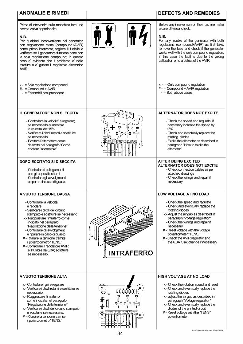
ECSO MANUAL MAY 2009 REVISION 04
ANOMALIE E RIMEDI
34
Prima di intervenire sulla macchina fare unaricerca visiva approfondita.
N.B.Per qualsiasi inconveniente nei generatoricon regolazione mista (compound+AVIR)come primo intervento, togliere il fusibile everificare se il generatore funziona bene conla sola regolazione compound; in questocaso e’ evidente che il problema e’ nellataratura o e’ guasto il regolatore elettronicoAVIR.
x - = Solo regolazione compound# - = Compound + AVIR - = Entrambi i casi precedenti
IL GENERATORE NON SI ECCITA
- Controllare la velocita’ e regolare; se necessario aumentare la velocita’ del 15% - Verificare i diodi rotanti e sostituire se necessario - Eccitare l’alternatore come descritto nel paragrafo “Come eccitare l’alternatore”
DOPO ECCITATO SI DISECCITA
- Controllare i collegamenti con gli appositi schemi - Controllare gli avvolgimenti e riparare in caso di guasto
A VUOTO TENSIONE BASSA
- Controllare la velocita’ e regolare - Verificare i diodi del circuito stampato e sostituire se necessario x - Riaggiustare l’intraferro come indicato nel paragrafo “Regolazione della tensione” - Controllare gli avvolgimenti e riparare in caso di guasto # - Ritarare la tensione tramite il potenziometro “TENS.” # - Controllare il regolatore AVIR e il fusibile da 6,3A; sostituire se necessario.
A VUOTO TENSIONE ALTA
x - Controllare i giri e regolare x - Verificare i diodi rotanti e sostituire se necessario x - Riaggiustare l’intraferro come indicato nel paragrafo “Regolazione della tensione” x - Verificare i diodi del circuito stampato e sostituire se necessario, # - Ritarare la tensione tramite il potenziometro “TENS.”
ALTERNATOR DOES NOT EXCITE
- Check the speed and regulate; if necessary increase the speed by 15% - Check and eventually replace the rotating diodes - Excite the alternator as described in paragraph "How to excite the alternator"
AFTER BEING EXCITEDALTERNATOR DOES NOT EXCITE - Check connection cables as per attached drawings - Check the wirings and repair if necessary
LOW VOLTAGE AT NO LOAD
- Check the speed and regulate - Check and eventually replace the rotating diodes x - Adjust the air gap as described in paragraph "Voltage regulation" - Check the wirings and repair if necessary # - Reset voltage with the voltage potentiometer “TENS.” # - Check the AVIR regulator and the 6.3A fuse; change if necessary
HIGH VOLTAGE AT NO LOAD
x - Check the rotation speed and reset x - Check and eventually replace the rotating diodes x - adjust the air gap as described in paragraph "Voltage regulation" x - Check and eventually replace the diodes of the printed circuit # - Reset voltage with the “TENS.” potentiometer
Before any intervention on the machine makea carefull visual check.
N.B.For any trouble of the generator with bothregulations (compound+AVIR) as first take,remove the fuse and check if the generatorworks well with the only compound regulation;in this case the fault is due to the wrongcalibration or to a defect of the AVIR.
x - = Only compound regulation# - = Compound + AVIR regulation - = Both above cases
DEFECTS AND REMEDIES
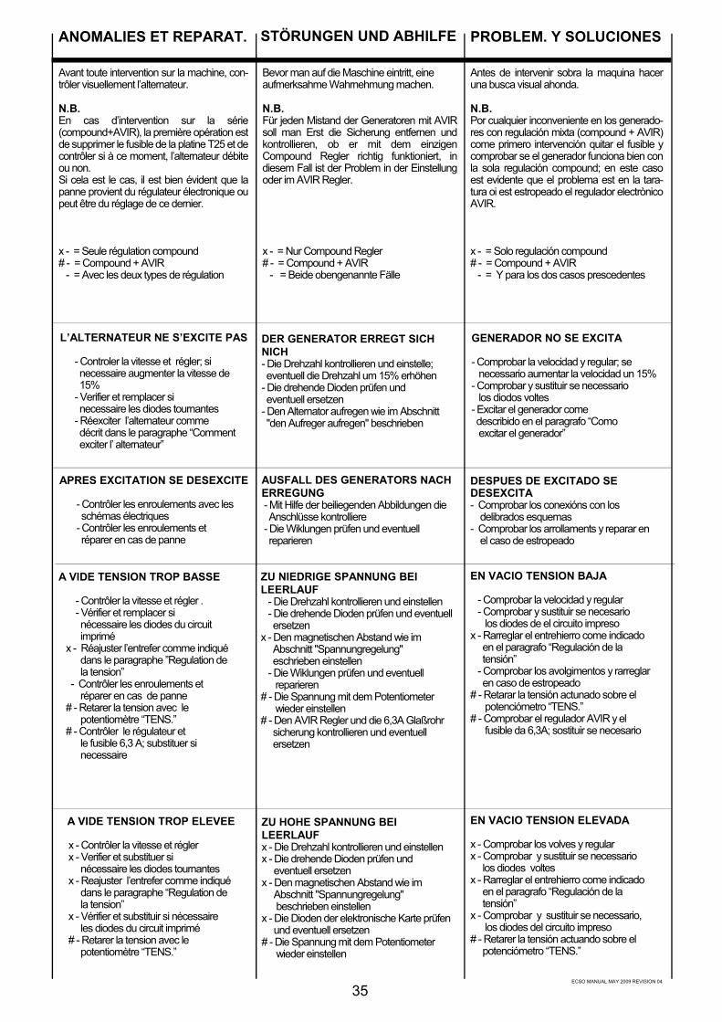
ECSO MANUAL MAY 2009 REVISION 04
35
L’ALTERNATEUR NE S’EXCITE PAS
- Controler la vitesse et régler; si necessaire augmenter la vitesse de 15% - Verifier et remplacer si necessaire les diodes tournantes - Réexciter l’alternateur comme décrit dans le paragraphe “Comment exciter l’ alternateur”
DER GENERATOR ERREGT SICHNICH- Die Drehzahl kontrollieren und einstelle; eventuell die Drehzahl um 15% erhöhen- Die drehende Dioden prüfen und eventuell ersetzen- Den Alternator aufregen wie im Abschnitt "den Aufreger aufregen" beschrieben
GENERADOR NO SE EXCITA
- Comprobar la velocidad y regular; se necessario aumentar la velocidad un 15%- Comprobar y sustituir se necessario los diodos voltes- Excitar el generador come describido en el paragrafo “Como excitar el generador”
APRES EXCITATION SE DESEXCITE
- Contrôler les enroulements avec les schémas électriques - Contrôler les enroulements et réparer en cas de panne
AUSFALL DES GENERATORS NACHERREGUNG - Mit Hilfe der beiliegenden Abbildungen die Anschlüsse kontrolliere - Die Wiklungen prüfen und eventuell reparieren
DESPUES DE EXCITADO SEDESEXCITA- Comprobar los conexións con los delibrados esquemas- Comprobar los arrollaments y reparar en el caso de estropeado
A VIDE TENSION TROP BASSE
- Contrôler la vitesse et régler . - Vérifier et remplacer si nécessaire les diodes du circuit imprimé x - Réajuster l’entrefer comme indiqué dans le paragraphe ”Regulation de la tension” - Contrôler les enroulements et réparer en cas de panne # - Retarer la tension avec le potentiomètre “TENS.” # - Contrôler le régulateur et le fusible 6,3 A; substituer si necessaire
ZU NIEDRIGE SPANNUNG BEILEERLAUF - Die Drehzahl kontrollieren und einstellen - Die drehende Dioden prüfen und eventuell ersetzenx - Den magnetischen Abstand wie im Abschnitt "Spannungregelung" eschrieben einstellen - Die Wiklungen prüfen und eventuell reparieren# - Die Spannung mit dem Potentiometer wieder einstellen# - Den AVIR Regler und die 6,3A Glaßrohr sicherung kontrollieren und eventuell ersetzen
EN VACIO TENSION BAJA
- Comprobar la velocidad y regular - Comprobar y sustituir se necesario los diodes de el circuito impresox - Rarreglar el entrehierro come indicado en el paragrafo “Regulación de la tensión” - Comprobar los avolgimentos y rarreglar en caso de estropeado# - Retarar la tensión actunado sobre el potenciómetro “TENS.”# - Comprobar el regulador AVIR y el fusible da 6,3A; sostituir se necesario
A VIDE TENSION TROP ELEVEE
x - Contrôler la vitesse et régler x - Verifier et substituer si nécessaire les diodes tournantes x - Reajuster l’entrefer comme indiqué dans le paragraphe “Regulation de la tension” x - Vérifier et substituir si nécessaire les diodes du circuit imprimé # - Retarer la tension avec le potentiomètre “TENS.”
ZU HOHE SPANNUNG BEILEERLAUFx - Die Drehzahl kontrollieren und einstellenx - Die drehende Dioden prüfen und eventuell ersetzenx - Den magnetischen Abstand wie im Abschnitt "Spannungregelung" beschrieben einstellenx - Die Dioden der elektronische Karte prüfen und eventuell ersetzen# - Die Spannung mit dem Potentiometer wieder einstellen
EN VACIO TENSION ELEVADA
x - Comprobar los volves y regularx - Comprobar y sustituir se necessario los diodes voltesx - Rarreglar el entrehierro come indicado en el paragrafo “Regulación de la tensión”x - Comprobar y sustituir se necessario, los diodes del circuito impreso# - Retarer la tensión actuando sobre el potenciómetro “TENS.”
Bevor man auf die Maschine eintritt, eineaufmerksahme Wahrnehmung machen.
N.B.Für jeden Mistand der Generatoren mit AVIRsoll man Erst die Sicherung entfernen undkontrollieren, ob er mit dem einzigenCompound Regler richtig funktioniert, indiesem Fall ist der Problem in der Einstellungoder im AVIR Regler.
x - = Nur Compound Regler# - = Compound + AVIR - = Beide obengenannte Fälle
STÖRUNGEN UND ABHILFEANOMALIES ET REPARAT. PROBLEM. Y SOLUCIONES
Avant toute intervention sur la machine, con-trôler visuellement l’alternateur.
N.B.En cas d’intervention sur la série(compound+AVIR), la première opération estde supprimer le fusible de la platine T25 et decontrôler si à ce moment, l’alternateur débiteou non.Si cela est le cas, il est bien évident que lapanne provient du régulateur électronique oupeut être du réglage de ce dernier.
x - = Seule régulation compound# - = Compound + AVIR - = Avec les deux types de régulation
Antes de intervenir sobra la maquina haceruna busca visual ahonda.
N.B.Por cualquier inconveniente en los generado-res con regulación mixta (compound + AVIR)come primero intervención quitar el fusible ycomprobar se el generador funciona bien conla sola regulación compound; en este casoest evidente que el problema est en la tara-tura oi est estropeado el regulador electrònicoAVIR.
x - = Solo regulación compound# - = Compound + AVIR - = Y para los dos casos prescedentes
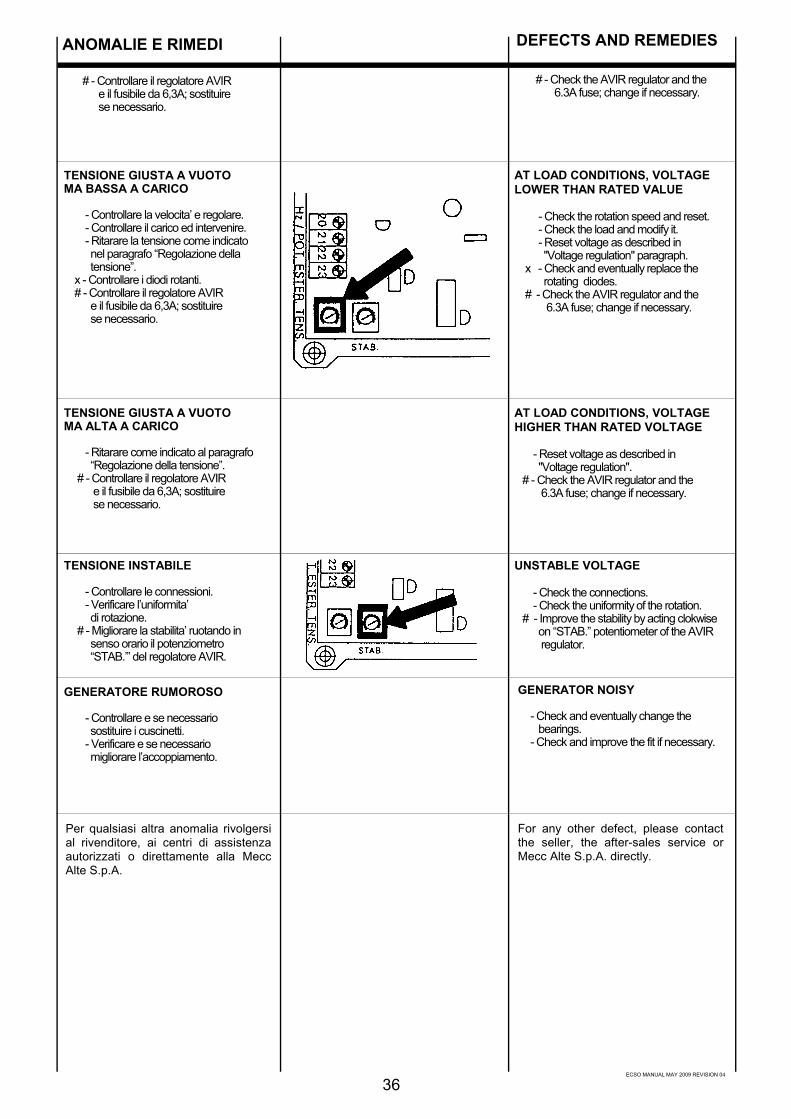
ECSO MANUAL MAY 2009 REVISION 04
ANOMALIE E RIMEDI
36
GENERATORE RUMOROSO
- Controllare e se necessario sostituire i cuscinetti. - Verificare e se necessario migliorare l’accoppiamento.
TENSIONE GIUSTA A VUOTOMA ALTA A CARICO
- Ritarare come indicato al paragrafo “Regolazione della tensione”. # - Controllare il regolatore AVIR e il fusibile da 6,3A; sostituire se necessario.
TENSIONE INSTABILE
- Controllare le connessioni. - Verificare l’uniformita’ di rotazione. # - Migliorare la stabilita’ ruotando in senso orario il potenziometro “STAB.’” del regolatore AVIR.
TENSIONE GIUSTA A VUOTOMA BASSA A CARICO
- Controllare la velocita’ e regolare. - Controllare il carico ed intervenire. - Ritarare la tensione come indicato nel paragrafo “Regolazione della tensione”. x - Controllare i diodi rotanti. # - Controllare il regolatore AVIR e il fusibile da 6,3A; sostituire se necessario.
# - Controllare il regolatore AVIR e il fusibile da 6,3A; sostituire se necessario.
AT LOAD CONDITIONS, VOLTAGELOWER THAN RATED VALUE
- Check the rotation speed and reset. - Check the load and modify it. - Reset voltage as described in "Voltage regulation" paragraph. x - Check and eventually replace the rotating diodes. # - Check the AVIR regulator and the 6.3A fuse; change if necessary.
UNSTABLE VOLTAGE
- Check the connections. - Check the uniformity of the rotation. # - Improve the stability by acting clokwise on “STAB.” potentiometer of the AVIR regulator.
AT LOAD CONDITIONS, VOLTAGEHIGHER THAN RATED VOLTAGE
- Reset voltage as described in "Voltage regulation". # - Check the AVIR regulator and the 6.3A fuse; change if necessary.
# - Check the AVIR regulator and the 6.3A fuse; change if necessary.
GENERATOR NOISY
- Check and eventually change the bearings. - Check and improve the fit if necessary.
DEFECTS AND REMEDIES
Per qualsiasi altra anomalia rivolgersial rivenditore, ai centri di assistenzaautorizzati o direttamente alla MeccAlte S.p.A.
For any other defect, please contactthe seller, the after-sales service orMecc Alte S.p.A. directly.
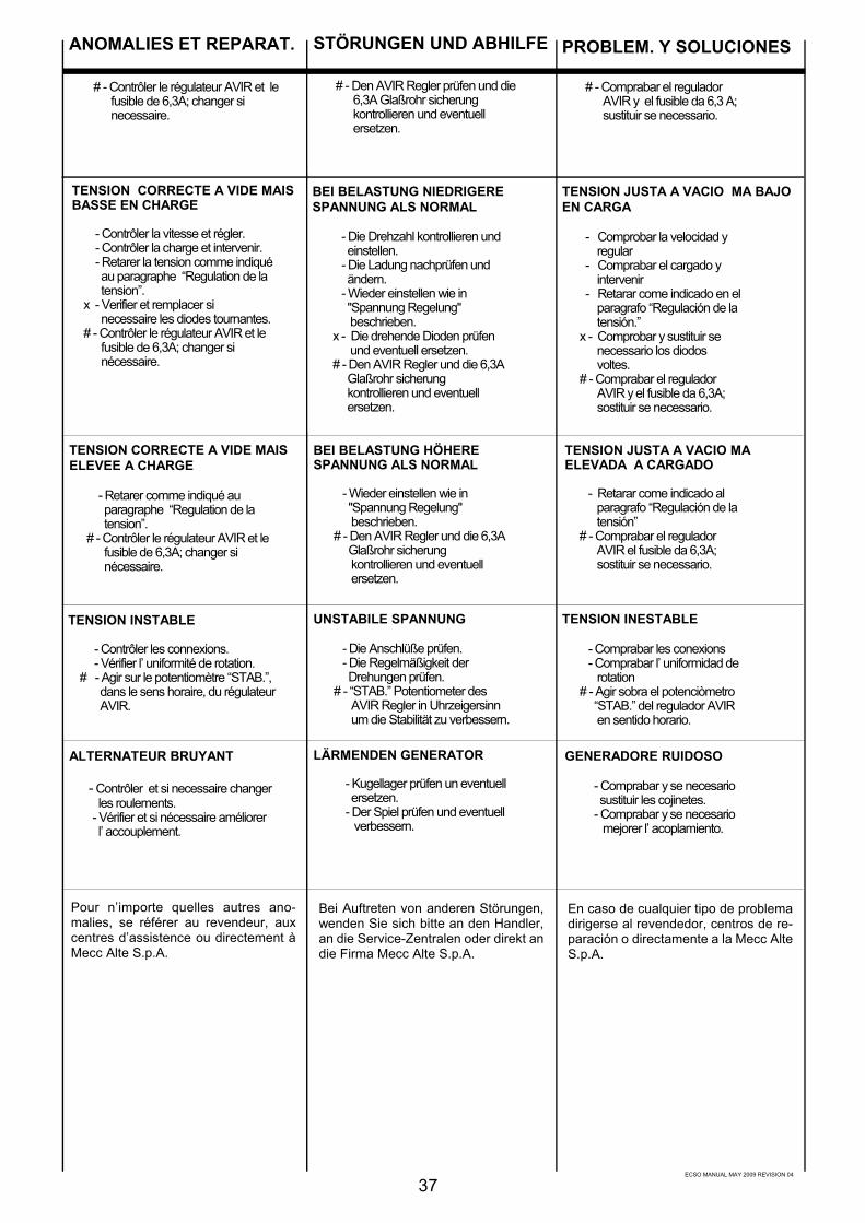
ECSO MANUAL MAY 2009 REVISION 04
37
TENSION CORRECTE A VIDE MAISBASSE EN CHARGE
- Contrôler la vitesse et régler. - Contrôler la charge et intervenir. - Retarer la tension comme indiqué au paragraphe “Regulation de la tension”. x - Verifier et remplacer si necessaire les diodes tournantes. # - Contrôler le régulateur AVIR et le fusible de 6,3A; changer si nécessaire.
BEI BELASTUNG NIEDRIGERESPANNUNG ALS NORMAL
- Die Drehzahl kontrollieren und einstellen. - Die Ladung nachprüfen und ändern. - Wieder einstellen wie in "Spannung Regelung" beschrieben. x - Die drehende Dioden prüfen und eventuell ersetzen. # - Den AVIR Regler und die 6,3A Glaßrohr sicherung kontrollieren und eventuell ersetzen.
TENSION JUSTA A VACIO MA BAJOEN CARGA
- Comprobar la velocidad y regular - Comprabar el cargado y intervenir - Retarar come indicado en el paragrafo “Regulación de la tensión.” x - Comprobar y sustituir se necessario los diodos voltes. # - Comprabar el regulador AVIR y el fusible da 6,3A; sostituir se necessario.
TENSION CORRECTE A VIDE MAISELEVEE A CHARGE
- Retarer comme indiqué au paragraphe “Regulation de la tension”. # - Contrôler le régulateur AVIR et le fusible de 6,3A; changer si nécessaire.
BEI BELASTUNG HÖHERESPANNUNG ALS NORMAL
- Wieder einstellen wie in "Spannung Regelung" beschrieben. # - Den AVIR Regler und die 6,3A Glaßrohr sicherung kontrollieren und eventuell ersetzen.
TENSION JUSTA A VACIO MAELEVADA A CARGADO
- Retarar come indicado al paragrafo “Regulación de la tensión” # - Comprabar el regulador AVIR el fusible da 6,3A; sostituir se necessario.
TENSION INSTABLE
- Contrôler les connexions. - Vérifier l’ uniformité de rotation. # - Agir sur le potentiomètre “STAB.”, dans le sens horaire, du régulateur AVIR.
UNSTABILE SPANNUNG
- Die Anschlüße prüfen. - Die Regelmäßigkeit der Drehungen prüfen. # - “STAB.” Potentiometer des AVIR Regler in Uhrzeigersinn um die Stabilität zu verbessern.
TENSION INESTABLE
- Comprabar les conexions - Comprabar l’ uniformidad de rotation # - Agir sobra el potenciòmetro “STAB.” del regulador AVIR en sentido horario.
# - Den AVIR Regler prüfen und die 6,3A Glaßrohr sicherung kontrollieren und eventuell ersetzen.
LÄRMENDEN GENERATOR
- Kugellager prüfen un eventuell ersetzen. - Der Spiel prüfen und eventuell verbessern.
ANOMALIES ET REPARAT. STÖRUNGEN UND ABHILFE PROBLEM. Y SOLUCIONES
# - Contrôler le régulateur AVIR et le fusible de 6,3A; changer si necessaire.
# - Comprabar el regulador AVIR y el fusible da 6,3 A; sustituir se necessario.
ALTERNATEUR BRUYANT
- Contrôler et si necessaire changer les roulements. - Vérifier et si nécessaire améliorer l’ accouplement.
GENERADORE RUIDOSO
- Comprabar y se necesario sustituir les cojinetes. - Comprabar y se necesario mejorer l’ acoplamiento.
Pour n’importe quelles autres ano-malies, se référer au revendeur, auxcentres d’assistence ou directement àMecc Alte S.p.A.
Bei Auftreten von anderen Störungen,wenden Sie sich bitte an den Handler,an die Service-Zentralen oder direkt andie Firma Mecc Alte S.p.A.
En caso de cualquier tipo de problemadirigerse al revendedor, centros de re-paración o directamente a la Mecc AlteS.p.A.

ECSO MANUAL MAY 2009 REVISION 04
38
ECSO 34
Disegno esploso enomenclativo
Exploded view andterminology
Vue eclaté etnomenclature
Explosionszeichungund Bezeichnung
Dibujo piezas de lamaquina ynomenclatura
ECSO 28N
ECSO 32

ECSO MANUAL MAY 2009 REVISION 0439
N. DENOMINAZIONE NAME DESIGNATION BEZEICHNUNG DENOMINACION
1 chiusura posteriore real seal tole de fermeture hinterer deckel cierre posterior
2 cuffia terminal box lid couvercle deckel tapa
4 trasformatorecompound
compoundingtransformer
transformateur decompoundage
compoundtransformator
transformadorcompound
5 morsettiera diutilizzazione
terminal board planchette àbornes
klemmbrett placa bornesterminal
6 circuito stampatocompound
compound printedcircuit
compound circuitimprimé
gedrucktecompoundschal tung
plaqueta circuitoimpreso compound
7 coperchio posteriore non drive end bracket flasque côté excitatrice hinteres gehause tapa posterior
8 carcassa con statore frame and stator carcasse avec stator gehause mit stator carcaza con estator
9 coperchio anteriore drive end bracket flasque avant vorderer gehause tapa anterior
9A coperchio anteriore MD35 drive end bracket MD35 flasque avant MD35 vorderer gehause MD35 cierre anterior MD35
10 statore eccitatrice exciter stator stator de l’excitatrice erregerstator estator excitatriz
11 ponte diodirotante
rotatingdiode
pont de diodetournant
rotierendediodenbruche
puente diodosgiratorios
12 mozzo hub bague nabe cubo
13 rotore eccitatrice exciter armature induit d’excitatrice erregeranker inducido excitatriz
14 induttore rotante rotor roue polaire rotor inducido rotante
15 ventola fan ventilateur lufter ventilador
16 flangia esterna copricuscinetto
exterior flange -bearing cover
chapeau deroulement ext.
aussenflansch -lagerdeckel
brida externa cubrecojinete
17 cuscinetto anteriore front bearing roulement avant vorderes lager cojinete anterior
18 flangia internacopri cuscinetto
interior flangebearing cover
chapeau de roulementint.
aussenflansch -lagerdeckel
brida externa cubrecojinete
19 cuscinetto posteriore rear bearing roulement arrière hinter lager cojinete posterior
21 morsetto isolatore insulated terminal borné isolée isolierte klemme terminal aislado
23 regolatore elettronicoAVIR
electronicregulatorAVIR
régulateurelectronique AVIR
elektronischer reglerAVIR
regulador electrónicoAVIR
24 morsettiera ausiliaria auxiliary terminal board bornes auxiliaires neben -klemmebrett regleta
28 tirante coperchi - S cover stay bolt - S tige de flasque - S zugstange - S tirante de la tapa - S
28 tirante coperchi - L cover stay bolt - L tige de flasque - L zugstange - L tirante de la tapa - L
39 retina di protezione B14 protection screen B14 grille de protect. B14 schutzgitter B14 rejilla protecciòn B14
39A retina di protez. MD35 protect.screen MD 35 grille de protect. MD35 schutzgitter MD35 rejilla de protec.MD35
40 anello compensatore fixing ring rondelle de bloquage compensator ring anillo compensadores
42 dispositivo di parallelo parallel device dispositif de parallèle statikwandler dispositivo deparalelo
59 mozzo portadischi coupling hub manchon porte disque nabe cubo portadiscos
60 dischi disc plates disques kupplungsscheiben discos
70 soppressore disturbiradio
radio disturbssuppressor
antiparasitage funk-enstorfilter supresor de radiointerferencias
94 carter posteriore rear case carter arrière hinteres gehaeuse carter posterior
95 pannelli laterali scatolamorsetti
terminal boardsidepanels
panneaux laterauxboite à bornes
seitenblecheklemmenkasten
panel lateral caja debornes
96 pannello anteriore scatolamorsetti
terminal board frontpanel
panneau avantboite à bornes
vorderes blechklemmenkasten
panel anterior caja debornes
97 pannello posteriorescatola morsetti
terminal boardrear panel
panneau arriereboite à bornes
hinterers blechklemmenkasten
panel posterior cajade bornes
99 anello bloccaggio dischi-distanziale
disc blocking ring-spacer
anneau blocagedisques
spannringdistanzscheiben
anillo de bloc.discos -separadores
104 pannello portacomponenti
component- carryngpanel
panneau supportcomposants
komponentenblechtafel panel portacomponentes
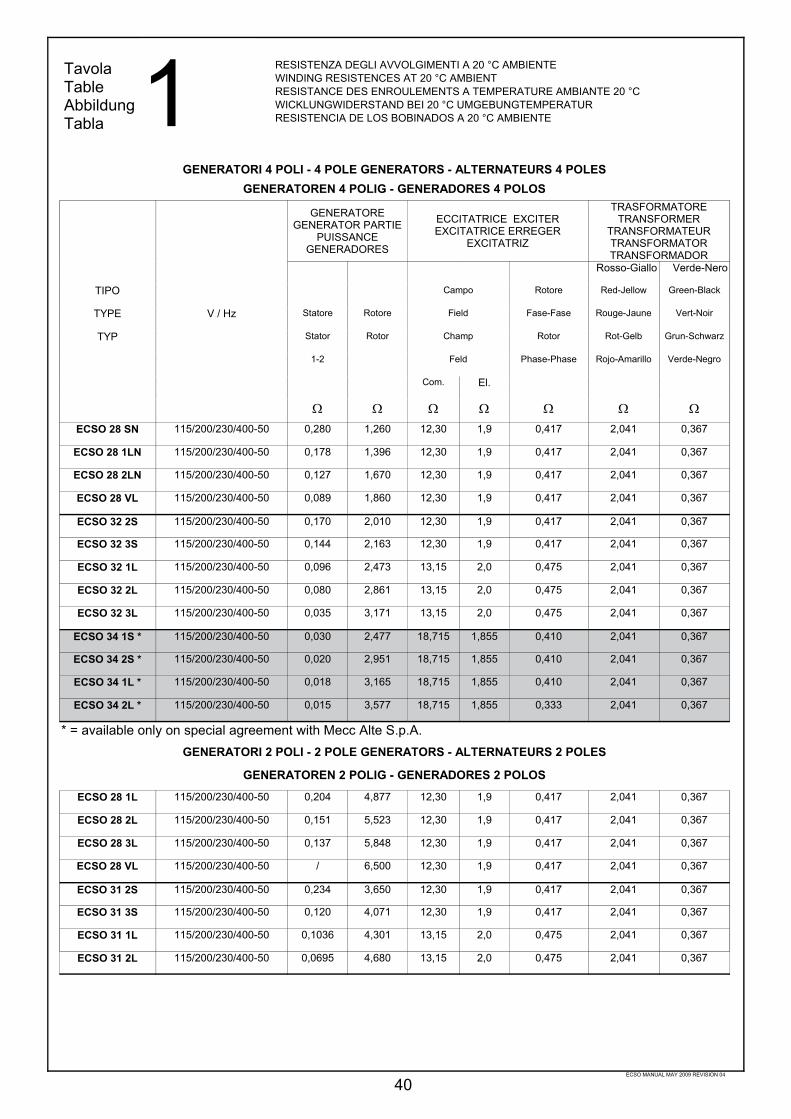
ECSO MANUAL MAY 2009 REVISION 04
40
TavolaTableAbbildungTabla 1 RESISTENZA DEGLI AVVOLGIMENTI A 20 °C AMBIENTE
WINDING RESISTENCES AT 20 °C AMBIENTRESISTANCE DES ENROULEMENTS A TEMPERATURE AMBIANTE 20 °CWICKLUNGWIDERSTAND BEI 20 °C UMGEBUNGTEMPERATURRESISTENCIA DE LOS BOBINADOS A 20 °C AMBIENTE
GENERATORI 4 POLI - 4 POLE GENERATORS - ALTERNATEURS 4 POLESGENERATOREN 4 POLIG - GENERADORES 4 POLOS
GENERATOREGENERATOR PARTIE
PUISSANCEGENERADORES
ECCITATRICE EXCITEREXCITATRICE ERREGER
EXCITATRIZ
TRASFORMATORETRANSFORMER
TRANSFORMATEURTRANSFORMATORTRANSFORMADOR
Rosso-Giallo Verde-Nero
TIPO Campo Rotore Red-Jellow Green-Black
TYPE V / Hz Statore Rotore Field Fase-Fase Rouge-Jaune Vert-Noir
TYP Stator Rotor Champ Rotor Rot-Gelb Grun-Schwarz
1-2 Feld Phase-Phase Rojo-Amarillo Verde-Negro
Com. El.
Ω Ω Ω Ω Ω Ω ΩECSO 28 SN 115/200/230/400-50 0,280 1,260 12,30 1,9 0,417 2,041 0,367
ECSO 28 1LN 115/200/230/400-50 0,178 1,396 12,30 1,9 0,417 2,041 0,367
ECSO 28 2LN 115/200/230/400-50 0,127 1,670 12,30 1,9 0,417 2,041 0,367
ECSO 28 VL 115/200/230/400-50 0,089 1,860 12,30 1,9 0,417 2,041 0,367
ECSO 32 2S 115/200/230/400-50 0,170 2,010 12,30 1,9 0,417 2,041 0,367
ECSO 32 3S 115/200/230/400-50 0,144 2,163 12,30 1,9 0,417 2,041 0,367
ECSO 32 1L 115/200/230/400-50 0,096 2,473 13,15 2,0 0,475 2,041 0,367
ECSO 32 2L 115/200/230/400-50 0,080 2,861 13,15 2,0 0,475 2,041 0,367
ECSO 32 3L 115/200/230/400-50 0,035 3,171 13,15 2,0 0,475 2,041 0,367
ECSO 34 1S * 115/200/230/400-50 0,030 2,477 18,715 1,855 0,410 2,041 0,367
ECSO 34 2S * 115/200/230/400-50 0,020 2,951 18,715 1,855 0,410 2,041 0,367
ECSO 34 1L * 115/200/230/400-50 0,018 3,165 18,715 1,855 0,410 2,041 0,367
ECSO 34 2L * 115/200/230/400-50 0,015 3,577 18,715 1,855 0,333 2,041 0,367
* = available only on special agreement with Mecc Alte S.p.A.GENERATORI 2 POLI - 2 POLE GENERATORS - ALTERNATEURS 2 POLES
GENERATOREN 2 POLIG - GENERADORES 2 POLOS
ECSO 28 1L 115/200/230/400-50 0,204 4,877 12,30 1,9 0,417 2,041 0,367
ECSO 28 2L 115/200/230/400-50 0,151 5,523 12,30 1,9 0,417 2,041 0,367
ECSO 28 3L 115/200/230/400-50 0,137 5,848 12,30 1,9 0,417 2,041 0,367
ECSO 28 VL 115/200/230/400-50 / 6,500 12,30 1,9 0,417 2,041 0,367
ECSO 31 2S 115/200/230/400-50 0,234 3,650 12,30 1,9 0,417 2,041 0,367
ECSO 31 3S 115/200/230/400-50 0,120 4,071 12,30 1,9 0,417 2,041 0,367
ECSO 31 1L 115/200/230/400-50 0,1036 4,301 13,15 2,0 0,475 2,041 0,367
ECSO 31 2L 115/200/230/400-50 0,0695 4,680 13,15 2,0 0,475 2,041 0,367

ECSO MANUAL MAY 2009 REVISION 04
41
TavolaTableAbbildungTabla 3
TavolaTableAbbildungTabla 2
COLLEGAMENTO A STELLASTAR CONNECTION
CONNECTION ETOILESTERNSCHALTUNG
CONEXION EN ESTRELLA
COLLEGAMENTO A TRIANGOLODELTA CONNECTION
CONNECTION TRIANGLEDREIECKSCHALTUNG
CONEXION EN TRIANGULO
COLLEGAMENTI GENERATORI A 12 FILICONNECTIONS FOR 12 LEAD ALTERNATORS
CONNECTIONS ALTERNATEURS 12 FILSANSCHLUSSE DER GENERATOREN MIT 12 WICKLUNSENDEN
CONEXION ALTERNADOR DE 12 HILOS
REGOLAZIONE DELLA TENSIONE ECSO SOLO COMPOUNDVOLTAGE REGULATION OF ECSO COMPOUND ONLYREGLAGE DE LA TENSION ECSO COMPOUND UNIQUEMENTSPANNUNGSEINSTELLUNG FUR NUR COMPOUND ECSOREGULACION DE LA TENSION ECSO SOLAMENTE COMPOUND
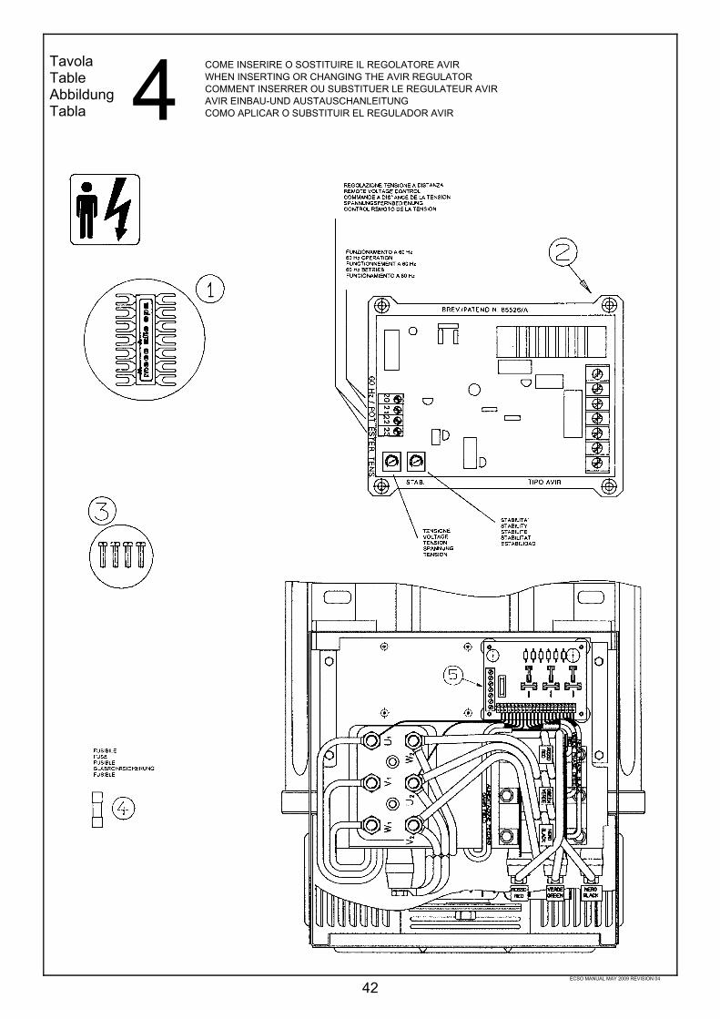
ECSO MANUAL MAY 2009 REVISION 04
42
TavolaTableAbbildungTabla 4 COME INSERIRE O SOSTITUIRE IL REGOLATORE AVIR
WHEN INSERTING OR CHANGING THE AVIR REGULATORCOMMENT INSERRER OU SUBSTITUER LE REGULATEUR AVIRAVIR EINBAU-UND AUSTAUSCHANLEITUNGCOMO APLICAR O SUBSTITUIR EL REGULADOR AVIR

ECSO MANUAL MAY 2009 REVISION 04
43
TavolaTableAbbildungTabla 5 SCHEMA ELETTRICO ECSO 6 MORSETTI (CON AVIR)
ECSO 6 WIRES ELECTRICAL DIAGRAM (WITH AVIR)SCHEMA ELECTRIQUE ECSO 6 BORNES (AVEC AVIR)SCHALT SCHEMA ECSO MIT 6 KLEMMEN (MIT AVIR)ESQUEMA ELECTRICO ECSO 6 HILOS (CON AVIR)
TavolaTableAbbildungTabla 6 SCHEMA ELETTRICO ECSO 12 MORSETTI (CON AVIR)
ECSO 12 WIRES ELECTRICAL DIAGRAM (WITH AVIR)SCHEMA ELECTRIQUE ECSO 12 BORNES (AVEC AVIR)SCHALT SCHEMA ECSO MIT 12 KLEMMEN (MIT AVIR)ESQUEMA ELECTRICO ECSO 12 HILOS (CON AVIR)
Il dispositivo di parallelo PD è opzionale. Il ponticello P abilita o disabilita il dispositivo se presente.The parallel device PD is optional. The link P activates or de-activates the parallel device, if it is present.Le dispositif the parallele PD est en option. Le pont P met ou supprime le circuit du dispositif de parallele.Die Parallelvorrichtung PD ist optional. Die Brucke P deaktiviert die Parallelvorrichtung, sofern vorhanden.El dispositivo de paralelo PD es opcional. El puenticillo P, se esta presente, activa o desactiva el dispositivo de paralelo.

ECSO MANUAL MAY 2009 REVISION 04
44
TavolaTableAbbildungTabla 7
TavolaTableAbbildungTabla 8
SCATOLA REGOLAZIONE 34 34 TERMINAL BOX BOITIER DE REGULATION 34 REGLERKASTEN 34 CAJA DE REGULACION 34
SCATOLA REGOLAZIONE 28-31-32TERMINAL BOX 28-31-32BOITIER DE REGULATION 28-31-32REGLERKASTEN 28-31-32CAJA DE REGULACION 28-31-32

ECSO MANUAL MAY 2009 REVISION 04
45
Tutti i cuscinetti sonoingrassati in fase dimontaggio.Grasso impiegato nor-malmente tipo SKF 28o corrispondente.
All bearings aregreased during as-sembly.Use SKF 28 orequivalent grease fornormal operation.
Tous les roulementssont graissès aumoment de l’assem-blage.Utiliser SKF 28 ouéquivalent pour opera-tion de maintenance.
Alle Lager werdenwährend der Montageeingefettet.Verwendetes Fett: TypSKF 28 oder gleich-wertiges.
Todos los cojinetesson engrasados enfase de montaje.La grasa normalmenteempleada es del tipoSKF 28 o equivalente.
Alternatore tipoAlternator type
Type alternateurGeneratortyp
Alternador tipo
Tipo cuscinettiBearing type
Type roulementLagertyp
Coijnete tipoL.A.D.E.
R.A.R.
L.O.A.O.D.E.R.A.V.
6309.2RS6312.2Z
6312.2RS6314.2Z
6207.2RS6309.2RS6309.2RS6311.2RS
28313234
Cuscinetti stagni:non sono necessariemanutenzioni per tuttoil periodo di funzio-namento (circa 30.000ore).
Sealed bearings:no maintenance isnecessary for theirentire working life(approximately 30.000hours).
Roulements etanches:aucune maintenancen’ est necessaire pourleur fonctionnement(pour approximative-ment 30.000 heures).
Dauergeschmierte la-ger. d.h.:wahrend der gesamtenFunktionszeit (etwa30.000 Studen) ist kei-nerlei Wartung notwen-ding.
Coijnetes sellados:no son necesariosmantenimientos entodo el periodo def u n c t i o n a m e n t o(aproximado 30.000horas).
TavolaTableAbbildungTabla 9 TABELLA CUSCINETTI E MANUTENZIONI PERIODICHE
PERIODIC MAINTENANCE AND BEARING TABLE TABLEAU DE MAINTENANCE DES ROULEMENTS TABELLE DER LAGER UND DER PERIODISCHEN INSTANDHALTUNG TABLA DE MANTENIMIENTO DE LOS COJINETES
TavolaTableAbbildungTabla 10RUMOROSITA’ - Pressione sonora (A) a vuoto
NOISE LEVEL - No load (A) sound pressure levelNIVEAU SONORE - Niveau sonore (A) à videGERÄUSCHPEGEL - Lautstärke (A) bei LeeraufRUIDO - Presion sonora (A) en vacio
50 Hz 60 Hz
1 m 7 m 1 m 7 m
ECSO 28N 69 58 73 62
ECSO 32 75 60 79 64
ECSO 34 79 65 83 69
GENERATORI A 4 POLI - 4 POLE GENERATORS - ALTERNATEURS 4 POLESGENERATOREN 4 POLIG - GENERADORES 4 POLOS
GENERATORI A 2 POLI - 2 POLE GENERATORS - ALTERNATEURS 2 POLESGENERATOREN 2 POLIG - GENERADORES 2 POLOS
50 Hz 60 Hz
1 m 7 m 1 m 7 m
ECSO 28 86 73 91 78
ECSO 31N 87 74 92 79

ECSO MANUAL MAY 2009 REVISION 04
46
VOLUMI D’ARIA E PESIAIR FLOW AND WEIGHTVOLUME D’AIR ET POIDSLUFTMENGE UND GEWICHTVOLUMEN DE AIRE E PESO
Volume d’aria Peso
TIPO Air flow Weight
TYPE Volume d’air Poids
TYP Luftmenge Gewicht
Volumen de aire Peso
m³/min
50 Hz 60 Hz Kg
ECSO 28 SN 110
ECSO 28 1LN 5,4 5,93 125
ECSO 28 2LN 142
ECSO 28 VL 168
ECSO 32 2S 202
ECSO 32 3S 217
ECSO 32 1L 11,7 14 251
ECSO 32 2L 283
ECSO 32 3L 301
ECSO 34 1S * 333
ECSO 34 2S * 399
ECSO 34 1L * 19,3 23 437
ECSO 34 2L * 471
TavolaTableAbbildungTabla 11
GENERATORI A 4 POLI - 4 POLE GENERATORSALTERNATEURS 4 POLES
GENERATOREN 4 POLIG - GENERADORES 4 POLOS
Volume d’aria Peso
TIPO Air flow Weight
TYPE Volume d’air Poids
TYP Luftmenge Gewicht
Volumen de aire Peso
m³/min
50 Hz 60 Hz Kg
ECSO 28 1L 132
ECSO 28 2L 10 11,2 139
ECSO 28 3L 144
ECSO 28 VL 159
ECSO 31 2SN 181
ECSO 31 3SN 22,4 27 207
ECSO 31 1LN 220
ECSO 31 2LN 239
GENERATORI A 2 POLI - 2 POLE GENERATORSALTERNATEURS 2 POLES
GENERATOREN 2 POLIG - GENERADORES 2 POLOS
* = available only on special agreement with Mecc Alte S.p.A.
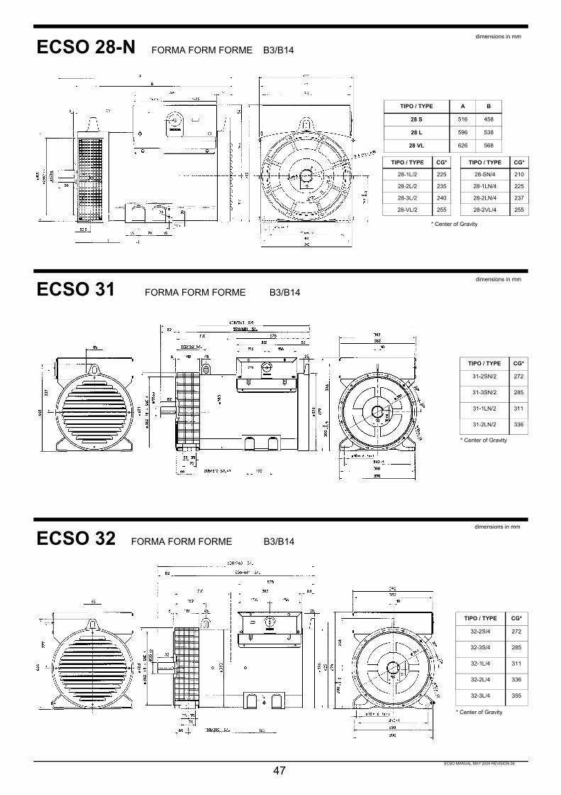
ECSO MANUAL MAY 2009 REVISION 04
47
ECSO 28-N FORMA FORM FORME B3/B14
ECSO 31 FORMA FORM FORME B3/B14
ECSO 32 FORMA FORM FORME B3/B14
TIPO / TYPE CG*
28-SN/4 210
28-1LN/4 225
28-2LN/4 237
28-2VL/4 255
TIPO / TYPE CG*
28-1L/2 225
28-2L/2 235
28-3L/2 240
28-VL/2 255
TIPO / TYPE A B
28 S 516 458
28 L 596 538
28 VL 626 568
* Center of Gravity
TIPO / TYPE CG*
31-2SN/2 272
31-3SN/2 285
31-1LN/2 311
31-2LN/2 336
* Center of Gravity
TIPO / TYPE CG*
32-2S/4 272
32-3S/4 285
32-1L/4 311
32-2L/4 336
32-3L/4 355
* Center of Gravity
dimensions in mm
dimensions in mm
dimensions in mm

ECSO MANUAL MAY 2009 REVISION 04
48
ECSO 28 FORMA FORM FORME MD 35
Flangia / FlangeBride / Flansch
SAEN°
O P Q N°fori
S α
5 356 314,3 333,4 8 11 22°30’4 403 362 381 12 11 15°3 451 409,6 428,6 12 11 15°2 490 447,7 466,7 12 11 15°
Giunti a dischiDisc coupling
Disque de monopalierScheibenkupplung
SAEN°
L d Q1 N°fori
S1 α1
6 ½ 30,2 215,9 200 6 9 60°7 ½ 30,2 241,3 222,25 8 9 45°8 62 263,52 244,47 6 11 60°10 53,8 314,32 295,27 8 11 45°
11 ½ 39,6 352,42 333,37 8 11 45°
TIPOTYPE
CG*
28-1L/2 24828-2L/2 25828-3L/2 26128-VL/2 280
TIPOTYPE
CG*
28-S/4 23528-1L/4 25028-2L/4 26228-VL/4 280
* Center of Gravity
ECSO 31 FORMA FORM FORME MD35dimensions in mm
Flangia / FlangeBride / Flansch
SAEN°
O P Q N°fori
S α
5 356 314,3 333,4 8 11 22°30’4 403 362 381 12 11 15°3 451 409,6 428,6 12 11 15°2 489 447,7 466,7 12 11 15°1 552 511,2 530,2 12 11 15°
Giunti a dischiDisc coupling
Disque de monopalierScheibenkupplung
SAEN°
L d Q1 N°fori
S1 α1
6 ½ 30,2 215,9 200 6 9 60°7 ½ 30,2 241,3 222,25 8 9 45°8 62 263,52 244,47 6 11 60°10 53,8 314,32 295,27 8 11 45°
11 ½ 39,6 352,42 333,37 8 11 45°
TIPOTYPE
CG*
31-2S/2 29631-3S/2 31031-1L/2 33531-2L/2 360
ECSO 32 FORMA FORM FORME MD35dimensions in mm
Flangia / FlangeBride / Flansch
SAEN°
O P Q N°fori
S α
5 356 314,3 333,4 8 11 22°30’4 403 362 381 12 11 15°3 451 409,6 428,6 12 11 15°2 489 447,7 466,7 12 11 15°1 552 511,2 530,2 12 11 15°
Giunti a dischiDisc coupling
Disque de monopalierScheibenkupplung
SAEN°
L d Q1 N°fori
S1 α1
6 ½ 30,2 215,9 200 6 9 60°7 ½ 30,2 241,3 222,25 8 9 45°
8 62 263,52 244,47 6 11 60°10 53,8 314,32 295,27 8 11 45°
11 ½ 39,6 352,42 333,37 8 11 45°
TIPOTYPE
CG*
32-2S/4 29632-3S/4 31032-1L/4 33532-2L/4 36032-3L/4 381
* Center of Gravity
dimensions in mm
* Center of Gravity

ECSO MANUAL MAY 2009 REVISION 04
ECSO 34 FORMA FORM FORME B3/B14
ECSO 34 FORMA FORM FORME MD 35
49
dimensions in mm
dimensions in mm
TIPO / TYPE CG*
34-1S/4 395
34-2S/4 425
34-1L/4 432
34-2L/4 458
TIPO / TYPE A B C I
34 S 809 704 297 227
34 L 909 804 397 317
* Center of Gravity
TIPOTYPE
CG*
34-1S/4 45534-2S/4 48534-1L/4 49034-2L/4 515
TIPO / TYPE A B C I34 S 823 763 346 35634 L 923 863 446 446
Giunti a dischiDisc coupling
Disque de monopalierScheibenkupplung
SAEN°
L d Q1 N°fori
S
10 53,8 314,32 295,27 8 1111½ 39,6 352,42 333,37 8 1114 25,4 466,72 438,15 8 14
Flangia / FlangeBride / Flansch
SAEN°
O P Q N°fori
3 451 409,6 428,6 122 489 447,7 466,7 121 552 511,2 530,2 12 * Center of Gravity

GARANTIEADie Firma Mecc Alte gibt 24Monate Garantie ab demZeitpunkt der Auslieferungvom Stammhaus oder ei-ner ihrer Filialen auf dieeinwandfreie Konstruktionund Qualität ihrer Genera-toren.BWahrend der genanntenPeriode repariert oder er-setzt Mecc Alte zu seinenKosten alle fehlerhaftenTeile, ohne Rucksicht obdirekt oder indirekt.
CMecc Alte behält sich dasRecht vor, die fehlerhaftenTeile frei Mecc Alte Vicenzazurückzufordern, zur Scha-densuntersuchung
DAlle eventuellen Kostenwie Transport, Fahrtkosten,Arbeitslohn für De-undMontage gehen zu Lastendes Kunden.
EDie Garantie in O.A. Zeitwird fur nachstehende Fak-toren ausgeschlossen:
1nicht korrekte Lagerung;
2Reparatur oder Mode-fizierung durch nicht vonMecc Alte autorisiertemPersonal;
3Gebrauch oder Einsatz beiKonditionen die nicht derNorm von Mecc Alte ent-sprechen;
4Überlast Gebrauch oderMontage anders als wofürdas Produkt bestimmt ist.
Die Garantie erlischt auch,wenn aus welchen Grun-den auch immer, derKunde in Zahlung überfälligist.
GARANTIAAMecc alte garantiza labuena construccion y cali-dad de los proprios produc-tos por 24 meses desde lafecha de salida de sus fabri-cas o de sus filiales.
BDurante disho periodo laMecc Alte se obliga a repa-rar o sustituir a su cargo, ensu establecimiento todasacquallas piezas que hubie-ran sido averiadas, sin ha-cerse cargo de otro tipo dedanos, directos o indirectos.
CLa decision acerca del reco-nocimiento de garantia estareservada exclusi-vamentea la Mecc Alte, previo exa-men de las partes averiadasque deberan permaneceren puerto franco o en supropia sede de Vicenza.
DTodos los eventuales ga-stos de transporte, viaje,transferencia o mano deobra, para el desmontaje ynuevo montaje, del alter-nador o elemento accio-nante seran siempre acargo del usuario.
ELa garantia caduca si du-rante el periodo descrito seprodujeran las siguientesanomalias:
1almacenaje en lugar inade-cuado;
2reparacion o modificacionpor personal no autorizadopor Mecc Alte;
3utilizacion o condiciones demanuntencion que contra-vengan las normas estable-cidas por Mecc Alte;
4sobrecarga o empleo enprestaciones distintas deaquellas para las que haestado suministrado.
La garantia cesa igual-mente en el momento queel cliente sea moroso depago, cualquiera que sea larazon.
GARANZIAALa Mecc Alte garantisce labuona costruzione e quali-ta' dei propri alternatori per24 mesi dalla data di spedi-zione dai propri stabilimentio filiali.
BDurante il suddetto periodola Mecc Alte si impegna ariparare o sostituire (a pro-prie spese) nella propriasede, quelle parti che si fos-sero avariate, senza pero’essere tenuta a risarcimentidi danni diretti o indiretti.
CLa decisione sul rico-noscimento o meno dellagaranzia e’ riservata esclu-sivamente alla Mecc Alteprevio esame delle partiavariate che dovranno per-venire in porto franco, allasua sede di Vicenza.
DTutte le eventuali spese diviaggio, trasferta, trasporto,mano d’opera per lo smon-taggio e rimontaggio dell’al-ternatore dall‘ap-parecchiatura azionantesono sempre a carico del-l’utente.
ELa garanzia decade se du-rante il periodo predetto, iprodotti fossero:
1immagazzinati in luogo nonadatto;
2riparati o modificati da per-sonale non autorizzatodalla Mecc Alte;
3usati o sottoposti a ma-nutenzione non in base allenorme stabilite dalla MeccAlte;
4sovraccaricati o impiegati inprestazioni diverse daquelle per le quali sono statiforniti.
La garanzia cessa comun-que qualora il cliente fosseinadempiente nei paga-menti per qualunque ra-gione.
50
GARANTIEALa société Mecc Alte ga-rantit la bonne constructionet qualité de ses produitspour une durée de 24 moisà compter de la date d'ex-pédition de ses usines defabrication ou filiales.
BDurant la période indiquée,Mecc Alte s’engage à répa-rer ou à remplacer (à prixéquivalent) dans la société,la partie qui serait endom-magée sans tou-tefois êtretenue de prendre en consi-dération les frais directs ouindirects.
CLa décision sur la prise encharge ou non de la garan-tie est réservée exclusive-ment à Mecc Alte sur exa-men préalable des piècesendommagées qui devrontparvenir en port Franco àl’usine de Vicenza.
DTout les éventuels frais devoyage, transfert, transport,main d’oeuvre pour le dé-montage de l’alternateursont toujours à la charge del’utilisateur.
ELa garantie ne s’appliquepas si durant la période indi-quée il y a:
1emmagasinement dans unlocal non adapté;
2réparations ou modifi-cations personnelles nonautorisées par Mecc Alte;
3usage et manutentions nonconformes aux normes éta-blies par Mecc Alte;
4surcharges et emplois desfonctions différentes de cel-les pour lequel ils sont four-nis.
Il est bien évident que lagarantie ne s’applique quesur le matériel payé en tota-lité.
WARRANTYAMecc Alte warrants thegood manufacture and qua-lity of all its products for 24months, starting from thetime of shipment from ourfactories or our branches.
BDuring said period MeccAlte obliges to repair re-place at its cost, at its works,all those parts which failedwithout any other liability ofany type, direct or indirect.
CThe decision for warrantyapproval is Mecc Alte’s ex-clusive right and subject to aprevious examination of thefailed parts which are to beforwarded fob Mecc AlteItaly for analysis.
DAll the eventual expensesconcerning travel, board,transport, and labour for as-sembly/disassembly of al-ternator from the drive unitare always at the user’scharge.
EThe warranty shall be void ifduring the above describedperiod the following anoma-lies should occur:
1inadeguate storage;
2repair or modification byunauthorized personnel;
3use or maintenance condi-tions which do not conformwhith norms established byMecc Alte;
4overload or applicationother than what the productwas meant for.
Warranty coverage also ex-pires whenever the client,for whatever reason, is latein payment.

VALLE D’AOSTAO.R.M.E. SNC DI JANIN SILVIA E JEANF.NE CHEZ FORNELLE 1111020 ARNAD (AO)TEL/FAX 0125/966108
PIEMONTER.G. ELECTRIX DI RIBOLDAZZI SNCVIA INDIPENDENZA, 928064 CARPIGNANO SESIANOVARATEL 0321/825740FAX 0321/825912
LOMBARDIAEAM di MARAZIO ANNIBALEVIA GEN.C.A. DALLA CHIESA, 1025017 LONATO DEL GARDA (BS)TEL 030/9913802FAX 030/9913787
ESSE ERRE ESSEVIA PO, 15420032 CORMANO MILANOTEL 02/36527703FAX 02/36527710
VENETOEMANUELE FIORASOVIA MONTE VERALDO, 11536073 CORNEDO (VI)TEL 0445/951190FAX 0445/951454
ITALIAMECC ALTE SPA36051 CREAZZO (VI) ITALIAVIA ROMA,20TEL 0444/396111FAX 0444/396166TELEX 480374 MECCAL I
ALBANIACEMA SH.P.K.RRUGA.KAVAJES ISHKOMBINATI TEKSTIL, FABRIKANGJYROSJESTIRANA - ALBANIATEL/FAX + 355 (0) 4 352562
AUSTRIAMOLL MOTORMECHATRONISCHEANTRIBSTECHNIK GESMBHINDUSTRIESTRASSE 8A-2000 STOCKERAUTEL 02266/63421-0FAX 02266/6342181
BELGIQUELAMBREGT N.VMOLENWEG 97 (IND.Z.4)2830 WILLEBROEKTEL. 00 32 3 844 28 32FAX 00 32 3 888 58 82
CANARY ISLESMECC ALTE ESPANA S.A.POLIGONO INDUSTRIAL CASAGRANDEPARCELA,12 D03180 TORREVIEJA (ALICANTE)TEL 096/6702152FAX 096/6700103
MARCHE - ABRUZZOELETTROMECCANICA FUTURA SRLVIA DEGLI ULIVI 87/165013 CITTA’ S.ANGELO (PE)TEL 085/950120FAX 085/9506859
LAZIO - MOLISEGIANCARLO MOSCATELLIVIA G.MATTEOTTI, 49/5100013 MENTANA (RM)TEL/FAX 06/9060707
CAMPANIAELETTR. REGA S.r.l.VIA MULITIELLO, 8580040 STRIANO (NA)TEL/FAX 081/8276655
CALABRIAA.R.T.E.S. LUCIA SRLTRAV. G. MARAFIOTI, 1288100 CATANZAROTEL 0961/773209FAX 0961/777835
ORIP.EG.VIA GIBERTI, 487100 COSENZATEL 0984/463943FAX 0984/849435
PUGLIACEL ELETTROMEC. DI LOI A. & C.VIA TRESSANTI 1° TRAVERSAVILLAGGIO ARTIGIANI71100 FOGGIATEL 0881/722520FAX 0881/561765
SICILIAELETTROMECCANICAODDO SEBASTIANOVIA ASMARA, SN98076 S.AGATA di MILITELLOMESSINATEL 0941/701171FAX 0941/723066
SARDEGNAFRANCO SAINAS & C. S.N.C.VIA TRENTINO, 16/1809127 CAGLIARITEL 070/290129FAX 070/270274
SAINAS FRANCO & C. S.N.C.C/O DEIANA PIEROZ.I. SETTORE 2 GOLFO ARANCI07026 OLBIA (SS)TEL/FAX 0789/58409
MECC ALTE ESPANA S.A.C/ RIO TAIBILLA, 2POLIG.IND. LOS VALEROS03178 BENIJOFAR (ALICANTE)TEL 096/6702152FAX 096/6700103
ALAVAAYERBE IND, DE MOTORES, S.A.AVDA. DEL ZADORRA, 10, APDO. 68901013 VITORIAALAVATEL 954-292297FAX 954-292298
ALICANTEONCINA ELECTRICIDAD, S.L.SR. JORGE ONCINAAVDA. MARE NOSTRUM, NAVE 2003006 ALICANTETEL Y FAX 96-5100934
ALMERIAOLIVARES DOMENE, S.L.AVDA. 28 DE FERRERO, 2104800 ALBOX (ALMERIA)TEL. 950 43 00 40FAX 950 63 32 95
BADAJOZELECTROMECANICA VAZQUEZ, S.L.FERNANDO MORENO MARQUEZ, 4506300 ZAFRA (BADAJOZ)TEL Y FAX 924-554039
BALEARESAGROSERVICIO BALEARCL. INFANTA PAZ, 5 BAJO07006 PALMA DE MALLORCABALEARESTEL Y FAX 971-460519
BARCELONAFILLS DE ROCHA I LOPEZ, S.L.C/ GOYA, 408903 HOSPITALET DELLOBREGATTEL 93-3333753FAX 93-3337236
BURGOSELECTRO CARCA BURGOSJAIME GARCA CAMARERO YOTRO, C.B.SAN PEDRO DE CARDEÑA, 2809002 BURGOSTEL Y FAX 947-204122
CANTABRIAELECTROCHISPA Y MECANICA DESANTOÑA, S.L.POL.IND. NAVE 3739740 SANTOÑACANTABRIATEL. Y FAX 942-661569
CASTELLONGENERADORES CASTELLON S.L.CARRER D'OSCA, 312530 BURRIANATEL. 964 58 67 18
MECC ALTE SPAIN
MECC ALTE SERVICE NETWORK EUROPE
51
ELETTR.TREVIGIANAVIA SILE,3331067 SILEA (TV)TEL/FAX 0422/360515
TRENTINO ALTO ADIGEELETTROMECC. SVALUTOVIA G. GOER MAHLZ. I. OVEST, 2639031 BRUNICO (BZ)TEL 0474/553033FAX 0474/551955
FRIULINUOVA ELETTROMECCANICACOOP. ARL.VIA TRAVNIK, 1334018 SAN DORLIGO DELLAVALLE - TSTEL 040 - 820120FAX 040 - 825997
LIGURIALEONCINI LUIGI S.N.C.VIA P.PASTORIONO, 128ROSSO16162 BOLZANETTO GENOVATEL 010/7450066FAX 010/7450154
EMILIA ROMAGNAOBERTI SRLVIA CRISTOFORO COLOMBO, 25/2744044 CASSANA (FE)TEL 0532/730219FAX 0532/732137
CENTRI ASSISTENZA AUTORIZZATI ITALIANI
La lista degli indirizzi è aggiornata al :The list of addresses was up-dated on :
La liste des adresses a été mise à jour le :Die Adressenliste wurde erstellt am :
La lista de las direcciones ha sido puesta aldía en fecha :
28/05/2009
Per verifiche successive, pregasi consultare il sito web : www.meccalte.comTo check recent changes, kindly consult our web site: www.meccalte.comVeuillez consulter www.meccalte.com pour les mises à jours regulieres.Aktualisierungen finden Sie unter: www.meccalte.comPara una verificación después de esta fecha, les rogamos consultar nuestro sitio web:www.meccalte.com
ROMANIAS.C. KOZ-SERVICE S.R.L.STR.PIETII Nr.7/C/24100 MIERCUREA-CIUCTel: +40 266 310 468Fax: +40 266 313 402
SPAINMECC ALTE ESPANA S.A.C/ RIO TAIBILLA,2POLIG. IND. LOS VALEROS03178 BENIJOFAR (ALICANTE)TEL 096/6702152FAX 096/6700103
SWEDENBUSCK & CO ABBOX 1600741221 GOETEBORGTEL 031/870900FAX 031/872712E-mail [email protected]
SWITZERLANDGENGA AGKIRCHWEG 129CH - 8102 OBERENGSTRINGENTEL +41/79677-9009FAX +41/434551056
GREECEA.ARGYRIOU & CO.AGIAS ANNIS 6A18233 RENTISTEL/ FAX +30 210 4916601TELEX 224807 VIMA GR
HOLLANDBRINKMANN & NIEMEIJERMOTOREN BVINDUSTRIETERREIN "DEENGELENBURG"ENGELENBURGSTRAAT 267391 AM TWELLOTEL +31(0)571-276900FAX +31(0)571-276800
HUNGARYTRESZEPITOGEP-KERESKEDELMI KFTVAS GEREBEN U. 229/AH - 1194 BUDAPESTATTN. MR. TRESZKAITEL.: +36-1-3480015FAX.: +36-1-3480016
IRELANDShanora PowerShanora LodgeNewtown RoadWexfordS. Ireland.TEL 00 353 53 41414FAX 00 353 53 44560
KOSOVOREFER TO ALBANIA
LATVIARIGAS DIZELISRIGASERVICE DEPARTMENTTEL +371 7381502
LITHUANIAREFER TO LATVIA
MACEDONIAREFER TO ALBANIA
MALTAZAHRA ENTERPRISES LTDST CATHERINE STREETATTARD BZN,12TEL 00356 216431961FAX 00356 216437842
MONTENEGROREFER TO ALBANIA
NORWAYGENETECH NORGE ASRINGSVEIEN 11A1368 STABEKKTEL. 47/675303320FAX 47/67530411POLSKABTH FASTBIURO TECHNICZNO HANDLOWEWALENDOW 5BPL - 05-830 NADARZYNTEL +48/224980698FAX +48/227314130
PORTUGALRIBASADO LDARUA DA SAUDE, 302901-893 SETUBALTEL 00351 265 790 490FAX 00351 265 790 496
PORTUGALTOTALENER LDAAV. ALBERTO VALENTE NO.1022950-313 PALMELATEL 00351 212 338 680FAX 00351 212 338 679
ANTONIOLI LUCIANOVIA DELL’ARTIGIANATO, 14/1643010 FONTANELLE DIROCCABIANCA (PR)TEL.0521/870351FAX 0521/370100
TOSCANAAUTOEL.GROSSETANA S.N.C.VIA NAPOLI, 2/658100 GROSSETOTEL 0564/24505FAX 0564/24891
STUCCHI RINALDOLOCALITA’ CASAGUANTI 105/B57016 ROSIGNANO MARITTIMO (LI)TEL 347/5911645FAX 02700444981
UMBRIAELETTR.F.V.VENTANNI G.& L.Z.I. MADONNA DEL MOROVIA CALABRIA06019 UMBERTIDE (PG)TEL/FAX 075/9415792
ELETTR. BERLIGI E DENTINI S.N.C.ZONA ARTIGIANALE06070 S.ENEA (PG)TEL/FAX 075/607291
CZECH & SLOVAC REPUBLICJAROSLAV VIT ELEKTRORADOVESNICE 186RADOVESNICE IICZ 28128 OKR. KOLINTEL/FAX +420 321 789 104
DENMARKTRANSMOTOR ApSLEMTORPVEJ 13-17DK-7620 LEMVIGTEL+45 9664 0977FAX +45 9664 0982
ENGLANDMECC ALTE U.K. LTD6 LANDS’ END WAYOAKHAM RUTLANDTEL 1572/771160FAX 1572/771161
ESTHONIAREFER TO LATVIAFINLANDHSA OY HOLLOLANSANKOAUTOMATIIKKA OYVIILAAJANKATU 1015520 LAHTITEL 03/884230FAX 03/8842310FRANCEMECC ALTE INTERNATIONAL S.A.Z.E. LA GAGNERIE 16330ST.AMANT DE BOIXETEL 0545/397562FAX 0545/398820
GERMANYMECC ALTE GENERATOREN GmbHENSENER WEG 21D-51149 KÖLNTEL 0 22 03 / 50 38 10FAX 0 22 03 / 50 37 96
MECC ALTE U.K. LTD6 LANDS’ END WAYOAKHAM RUTLANDTEL 1572/771160FAX 1572/771161
A & M GENERATORSUNIT 2KIDWELLY IND. ESTATEPEMBREY ROADKIDWELLY SA17 4TFTEL 01267 237078MOBILE 07814 544019
ASHVALE ENGINEERING LTD54 BELFAST ROADBALLYNAHINCHIRELANDBT24 8EBPHONE: 02897562480FAX: 02897562988
ADDICOTT ELECTRICS LtdQUAY ROADTEIGNMOUTHDEVONTQ14 8ELTEL 01626 774087/772332FAX 01626 778463
HOUGHTON INTERNATIONALUNIT 3FISHER INDUSTRAL ESTATEWALKERNEWCASTLENE6 4LTTEL 0191 234 3000FAX 0191 263 7873
HUTCHINSON POWER PRODUCTS5 GRANGE ROADDRUM RAINEYMAGHERAFELTCO DOWNBT45 5ALPHONE: 02879634440FAX: 02879631211
MERLIN124 WAYHILL ROADANDOVERHANTSSP10 3NPTEL. 08700623349FAX 08700623350
PEDEN POWER PRODUCTSSTATION ROAD IND ESTMAGHERAFELT COLONDONDERRYNORTHERN IRELANDTEL. 0279 632609FAX 02879 633707
POWERSOURCE PROJECTS LTDPOWERPRO HOUSECAPITAL PARK INDUSTRIALESTATECOMBE LANEWORMLEYGODALMING SURREY GU8 5TJTEL +44 (0)1428 684980FAX +44 (0)1428 687979
MECC ALTE UK/EIRE
MECC ALTE GENERATOREN GmbHENSENER WEG 21D-51149 KÖLNTEL 0 22 03 / 50 38 10FAX 0 22 03 / 50 37 96
01468 BOXDORFG. GLASERMOTOREN FRANKERINGSTR. 18TEL 0351/2076810FAX 0351/2076829
03253 DOBERLUG-KIRCHHAINKARL-HEINZ FROESCHKEELEKTROMOTOREN-SERVICESUEDSTR. 45TEL 035322/2624FAX 035322/2635
04129 LEIPZIGA. HENTSCHELELEKTROMASCHINENBAUWERKSTAETTENWEG 6TEL 0341/3015953FAX 0341/3015953
04651 BAD LAUSICKG. LEHMANBLITZSCHUTZANLAGENBORNAER STR.72TEL 034345/723-0FAX 034345/723-20
04758 OSCHATZELEKTRO-MECHANIK GmbHWELLERSWÄLDER WEG 11TEL 03434/622555FAX 03434/622567
08012 ZWICKAURELMA SERVICE GmbHELEKTROMASCHINENAM BAHNHOF 7TEL 0375/81849-0FAX 0375/81849-22
08228 RODEWISCHBERND SCHWABEELEKTROMASCHINENBAUSTIFTSTR., 4TEL 03744/33176FAX 03744/33176
09380 THALHEIM/ERZGEB.ELEKTROM. & TECHNIK GmbHFRIEDRICHSTR. 14ATEL 03721/84313FAX 03721/84256
13053 BERLINKEMNA UND MICHAELISSERVICE GMBHPLAUENER STR. 163TEL. 030/88496906FAX 030/88496908
13405 BERLINHEINZ GRAFELEKTROMEISTERSCHMALENBACHSTR. 10TEL 030/40632661FAX 030/40632663
17321 LÖCKNITZHERR MATZELEKTROMASCHINEN E G.STRAβE D. REPUBLIK 14bTEL 039754/20331FAX 039754/20331
18059 ROSTOCKIBH - ING BURO HARMSCHWAANER LANDSTR, 110TEL 0381/445125FAX 0381/445126
22045 HAMBURGRAMMENZWEIGELEKTROMASCHINENBAU GMBHALBERT-SCHWEITZER-RING 15TEL 040/6682808FAX 040/664902
22848 NORDERSTEDTIBH - ING BURO HARMGUTENBERGRING, 35TEL 040/5230520FAX 040/5281174
27446 SELSINGENPAPEHAAßELER STR. 1TEL: 04284/930410FAX 04284/9304124
30519 HANNOVERHELMKE & CO.HERR VON DER RECKEGARVENSTR, 5TEL 0511/8703128FAX 0511/863930
39126 MAGDEBURGEINBECKELEKTROMOTORENGUTENSWEGER STR. 15TEL 0391/5051722FAX 0391/5051723
48231 WARENDORFTIPPKOTTER GmbHELKTROMASCHINENBAUVELSEN 49TEL 02584/9302-0FAX 02584/930250
50968 KOLNELMOT BOLLIG & BEYENBURG oHGMERTENER STR. 1ATEL 0221/382739FAX 0221/385478
55120 MAINZ-MOMBACHFREY GmbHELEKTROMASCHINENBAUINDUSTRIESTR, 44TEL 06131/969620FAX 06131/684396
56729 KEHRIGFUHRMANNELKTROMOTORENMAYENER STR., 16TEL 02651/3715FAX 02651/76502
66115 SAARBRUCKENKLUG & KAYSER GmbHELEKTROMECH. WERKSTATTEBRUNNENSTR/BAHNGELANDETEL 0681/776191FAX 0681/776460
68169 MANNHEIMMOWITECAUGUSTO AGOSTINORUDOLF-DIESEL-STR. 8-10TEL 0621/3212930FAX 0621/3212931
72762 REUTLINGENG. MAIER GmbHELEKTROTECHNIKGUSTAV-SCHWAB - STR, 14/20TEL 07121/26900FAX 07121/269090
73033 GOPPINGENW. KRAUTER GmbHSTROMAGGREGATESIEMENSSTR., 5TEL 07161/73333FAX 07161/69612
75050 GEMMINGENELMER-ELEKTRO-SERVICEZIEGELEISTR. 22TEL 07267/911163FAX 07267/911165
77652 OFFENBURGBRUNO SCHNEIDERELEKTROMOTORENWINDSCHLAGER STR., 95 ATEL 0781/25701FAX 0781/25698
79108 FREIBURGBOHLER ANTRIEBSTECHNIKHERR PLAGAWEIßERLENSTR., 1GTEL 0761/130970FAX 0761/1309755
82538 GERETSRIEDMAX MOCKELEKTROMASCHINENBAULEITENSTR. 34TEL 08171/18823FAX 0817/26361
85235 WAGENHOFENKISTLERUMBACHER STR. 2TEL. 08143/556655-0FAX 08143/556655-98
93059 REGENSBURGELEKTRO HERMANN WEICHPFAFFENSTEINER WEG, 8/10TEL 0941/85612FAX 0941/897419
97514 OBERAURACHLUDWIG LIPS ELEKTROOT TRETZENDORFWEISBRUNNER WEG 8TEL 09522/1279FAX 09522/7505
98574 SCHMALKALDENANSCHUTZ GmbHELEKTROMOTOREN SERVICEROTHWEG, 4ATEL 03683/402567FAX 03683/62261
WEST SKELSTON SERVICESUNIT 173HEATH HALL IND ESTDUMFRIESSCOTLANDDG1 3PHTEL. 01387 256536FAX 01387 269887
MECC ALTE GERMANY
52
CORDOBABOBINADOS PASTOR S.L.ING. RIVERAS/N (POLIG. AMARGACENA)14013 CORDOBATEL 957 34 31 32FAX 957 34 31 33
CIUDAD REALGEMOSERRONDA DE LA ESTACION, 2313170 MIGUELTURRACIUDAD REALTEL 926-241775
GERONAELECTROMECANIQUES MATA, S.A.SANT ANDREU, 67-6917834 MATAGERONATEL 972-572508FAX 972-582674
GRANADATALLERES ELECTROMECANICOSPEMA S.L.POLIGONO TECNOLOGICO 8818151OGUIJARESGRANADATEL. 958507033FAX 958507160
GUADALAJARAMULTILEC, C.B.FRANCISCO ARITIO, 117, NAVE 2419004 GUADALAJARATEL Y FAX 949-202136
GUIPUZCOAAIZPURU, S.A.ESTACIOKO KALEA, 2120750 ZUMAIAGUIPUZCOATEL 943-861327FAX 943-860020
HUELVACOMERCIAL ELECTRICAONUBENSE, S.A.SR. FCO. GARCIAAVDA. NORTE, S/N21080 HUELVATEL 955-248622
HUESCAAMADEO ORDUNA, S.A.SAN URBEZ, 8-1222005 HUESCATEL. : 974-211176FAX : 974-211206
LA CORUÑAGRUPOS ELEC, LESTON, S.L.CL. GUTEMBERG, 40, P.I.LA GRELA15008 LA CORUÑATEL. : 981-250024FAX : 981-268299
LA RIOJASERLUSPOLIGONO PORTALADACALLE EL CHOZO N° 30LOGROÑOTEL/FAX : 941 244 872
SEVILLAELECTROMECANICA MARTINEZ, S.C.POL, EL PINO, PARCELA 17, NAVE 4741016 SEVILLATEL 95-4255602FAX 95-4251017
VALENCIAHNOS. SALES VALLS, S.A.CL. COLON, 64- PRENTE, N°146290 ALCACERVALENCIATEL 96-1231180FAX 96-1240076
VIGOCERVIMAR, S.L.BEIRAMAR, 117 BAJO36028 VIGOTEL 986-206442FAX 986-204450
ZARAGOZASORILUX, S.L.DEBAJO DE LA VENTA, NAVE 2250410 CUARTE HUERVAZARAGOZATEL 976-503963FAX 976-504515
LUGOUNISOLDA, S.L.CL, ARIAS DE ARQUIETO, S/N27680 SARRIALUGOTEL 982-533406FAX 982-532200
MADRIDVESERTEC, S.L.CL.PLOMO, 17, POL.IND. AIMAYR28330 SAN MARTIN DE LA VEGAMADRIDTEL. : 91-6915704FAX: 91-6920721
MURCIAALCARAZ LARRIBA, MANUELDR. PELAYO SIMARRO, 13, 1°30730 SAN JAVIERMURCIATEL. : 968-190036
NAVARRABOBINADOS LABRIT, S.L.POL. TALLUNTXE, 2, CL. B, N° 8031110 NOAIN (NAVARRA)TEL 948-312031FAX 948-312012
PRAMAC UK LtdCROWN IND PARKDUKESTOWNTREDECARGWENTNP22 4EFTEL. 01495 713300FAX 01495 718766
SHANORA POWERSHANORA LODGENEWTOWN ROADWEXFORDS IRELANDTEL 00 353 53 41414FAX 00 353 53 44560
MECC ALTE SERVICE WORLDWIDE
DPT. 19 VOIR 16
DPT. 20FERRATORUE NICOLAS PERALDI20000 AJACCIOTEL. 04.95.22.42.36FAX 04.95.22.17.67
DPT. 21S.N.J.B.10 RUE J DAGUERRE21300 CHENOVETEL. 03.80.52.373.34FAX 03.80.52.373.62
DPT. 22MOTELEC7 RUE A.LUMIEREZ.I.22000 ST. BRIEUCTEL. 02.96.33.50.60FAX 02.96.61.50.48
DPT. 23 VOIR 16
DPT. 24SUDER & FILS23 AVENUE LOUIS SUDER24430 MARSAC SUR L’ISLETEL. 05.53.02.76.20FAX 05.53.04.79.15
DPT. 25 VOIR 16
DPT. 26ELECTRO BOBINAGEPERRINES & FRERES(SAS)76 AVENUE DE MARSEILLE26000 VALENCETEL. 04.75.78.30.76FAX 04.75.81.23.77
DPT. 27 VOIR 16DPT. 28 VOIR 16
DPT. 29A.R.C.E.M.ZI KERVINRUE MARCELIN BERTHELOT29600 SAINT MARTIN DESCHAMPSTEL. 02.98.88.55.65FAX 02.98.88.78.42
DPT. 30SOBELEC534 AV. DOCTEUR FLEMING30900 NIMESTEL. 04.66..62.14.63FAX 04.66..62.15.71
DPT. 31ETS LAURENT6 RUE ANDRE CITROEN31130 BALMATEL. 05.61.48.42.14FAX 05.61.26.34.99
DPT. 32 VOIR 16
DPT. 33STE NOUVELLE SEMIBEN83 COURS E. VAILLANT33000 BORDEAUXTEL. 05.56.39.68.44FAX 05.56.50.95.22
ALGERIADIESELEC7 RUE KADDOUR RAHIMHUSSEIN - DeyALGERALGERIETel : 00 213 21 49 50 54 - 55 - 56FAX : 00 213 21 23 47 68
ANGOLAMACONANG LDARUA MANUEL AUGUSTO DOSSANTOS, 28 - 1°LUANDATEL 00244-2396017FAX 00244-2330876
CENTRAL AFRICAN REPUBLICREFER TO KENYA (NGINU)
CHADREFER TO KENYA (NGINU)
EGYPTTHE PIPELINES SERVICES CO.BARKI BROS9, EL-KAMEL MOHAMED St.ZAMALEKCAIRO EGYPTTEL ( 02 ) 7365544 / 7369217FAX ( 02 ) 7361373KENYACGM AFRICACOMPANY GENERATORMACHINES (K) LIMITEDP.O. BOX 230 MTWAPATEL +254 +11 473208 - 473170FAX +254 +11 475625NGINU POWER ENGINEERING LTDP.O. Box 33663-00600 NairobiTEL +254 20 783803FAX +254 20 780493
LESOTOREFER TO SOUTH AFRICA
MALAWIREFER TO SOUTH AFRICAMAROCCOCBE34 BOULEVARD BATILI-MED BENMEKHIROCHES NOIRES20300 CASABLANCAFAX 00212.22.40.81.85MOZAMBIQUEREFER TO SOUTH AFRICANAMIBIAELWERE5,BOHR STREETWINDHOEK - NAMIBIAP.O.BOX 80380 - WINDHOEKNAMIBIATEL 061/228298 - 230713FAX 061/33921NIGERREFER TO KENYA (NGINU)
NIGERIAINTERNATIONAL DIESEL SALES LTD198B ISALE EKO AVEDOLPHIN ASTATEIKOYI - LAGOS - NIGERIATEL 01/2694430FAX 01/2694458SOUTH AFRICASALISTER DIESELS (PTY) LTD3 LEEWENHOEK STREETPO BOX 1048VEREENIGING 1930 - RSA.TEL +27 16 422 5501FAX +27 16 422 1697/0607SUDANPOWERPAC COMPANY LTDPOWERPAC HOUSETENNIS COMPLEXAFRICA ROAD-AIR PORT AREAKHARTOUM - SUDANTEL +249 155135941FAX +249 83490783
SWAZILANDREFER TO SOUTH AFRICA
TANZANIAREFER TO SOUTH AFRICA
TUNISIAPROMOTECHNI S.A.Z.I. - CITE DISPENSAIRE2013 BEN AROUSTEL 01/385990FAX 01/383509
ZAMBIAREFER TO SOUTH AFRICA
ZIMBABWEREFER TO SOUTH AFRICA
AFRICA
53
MECC ALTE FRANCEMECC ALTE INTERNATIONAL S.A.Z.E.LA GAGNERIE16330 ST.AMANT DE BOIXETEL 05.45.39.75.62FAX 05.45.39.88.20
DPT. 01FLASHELECZI SEREINE01390 ST.ANDRE DE CORCYTEL. 04.72.26.12.59FAX 04.72.26.45.31DPT. 02 VOIR 16DPT. 03 VOIR 16DPT. 04 VOIR 16DPT. 05ROSTANT SARLZA LA JUSTICE05000 LE GAPTEL. 04.92.53.90.10FAX 04.92.52.04.27DPT. 06LUZORO MOTORZI FUON SANTA06340 NICE LA TRINITETEL. 04.97.00.10.20FAX 04.97.00.10.21
DPT. 07GASCON42 BOULEVARD J. MATHON07200 AUBENASTEL. 04.75.35.07.66FAX 04.75.38.17.04DPT. 08DOSSOT22 RUE DES SOURCES08000 CHARLEVILLES MEZIERESTEL. 03.24.59.75.15FAX 03.24.37.25.80
DPT. 09 VOIR 16
DPT. 10HALLIER57 RUE H. DUNANT10800 ST.JULIEN LES VILLASTEL. 03.25.71.30.29FAX 03.25.82.58.08
DPT. 11 VOIR 16
DPT. 12MASSABUAU SARLRUE ANTOINE12100 MILLAUTEL. 05.65.60.08.90FAX 05.65.61.15.64
DPT. 13 VOIR 16
DPT. 14BORELECAVENUE CARRIERES14760 BRELLEVILLE S/ODONTEL. 02.31.71.13.71FAX 02.31.26.53.81
DPT. 15 VOIR 16
DPT. 16MECC ALTE INTERNATIONAL S.A.ZE DE LA GAGNERIE16330 ST.AMANT DE BOIXETEL. 05.45.39.75.62FAX 05.45.39.88.20
DPT. 17 VOIR 16
DPT. 18SAETRUE ANDRE CHARLES BOULLEZI MALITORNE18230 ST. DOULCHARDTEL. 02.48.70.82.92FAX 02.48.70.71.50
DPT. 34LOCAWATT995 QUAI DES MOULINS34200 SETETEL. 04.67.18.66.00FAX 04.67.18.66.07
DPT. 35ROULINZA MIVOIE35136 ST. JACQUES DE LALANDETEL. 02.99.35.35.35FAX 02.99.35.35.36
DPT. 36EQUIPEMENT ELECTRIQUE30 RUE CANTRELLE36000 CHATEAUROUXTEL 02.54.34.04.59FAX 02.54.22.53.90
DPT. 37LEPRONBP N°1VALLERES37190 AZAY LE RIDEAUTEL. 02.47.45.45.50FAX 02.47.45.35.75
DPT. 38 VOIR 16DPT. 39 VOIR 16
DPT. 40SUD BOBINAGEROUTE DE MONT MARSAN40990 ST. PAUL LES DAXTEL. 05.58.91.69.69FAX 05.58.91.78.81
DPT. 41BEFIM10 RUE INDUSTRIE41400 MONTRICHARDTEL. 02.54.32.25.47FAX 02.54.32.46.43
DPT. 42 VOIR 16DPT. 43 VOIR 16DPT. 44 VOIR 16
DPT. 45OURY48 RUE DE LA BATARDIERE45140 ST JEAN DE LA RUELLETEL. 02.38.43.23.36FAX 02.37.43.49.40
DPT. 46 VOIR 16
DPT. 47BERBIGUIER5 RUE ANDRE BERGER47300 VILLENEUVE SUR LOTTEL. 05.53.70.37.04FAX 05.53.70.61.67
DPT. 48RUBIO8 RUE CARRIERES48000 MENDETEL. 04.66.65.02.70FAX 04.66.49.33.45
DPT. 49 VOIR 16DPT. 50 VOIR 16
DPT. 51NAUDE & FILS15 PLACE ST. NICAISE51100 REIMSTEL. 03.26.85.32.77FAX 03.26.97.85.58
DPT. 52 VOIR 16DPT. 53 VOIR 16DPT. 54 VOIR 16DPT. 55 VOIR 16DPT. 56 VOIR 16DPT. 57 VOIR 16DPT. 58 VOIR 16
DPT. 59PREVOST622 RUE JEAN PERRIN59500 DOUAITEL. 03.27.95.76.96FAX 03.27.95.76.97
DPT. 60SEIBO6, RUE DU CHAMP DESCOSAQUES60400 NOYONTEL 04.44.44.14.96FAX 04.44.09.04.12
DPT. 61 VOIR 16DPT. 62 VOIR 16
DPT. 63CMERUE DES FRERES LUMIERES63430 PONT DU CHATEAUTEL. 04.73.83.38.50FAX 04.73.83.38.51
DPT. 64 VOIR 16DPT. 65 VOIR 16DPT. 66 VOIR 16DPT. 67 VOIR 16DPT. 68 VOIR 16
DPT. 69BEILES PETIT PASSELOUP69400 VILLEFRANCHE SUR SAONETEL. 04.74.62.80.11FAX 04.74.68.41.82
DPT. 70 VOIR 16
DPT. 71BOBINAGE PRUDHOMME39 RUE FLANDINES71000 MACONTEL. 03.85.34.77.76FAX 03.85.34.29.77
DPT. 72SMEM156 AVENUE DU PANORAMA72100 LE MANSTEL. 02.43.84.66.40FAX 02.43.72.34.90
DPT. 73GIRARD330 CHEMIN DE LA ROTONDE73000 CHAMBERYTEL. 04.79.62.00.54FAX 04.79.62.61.65
DPT. 74SECA LOCATION13 RUE CALIFORNIEZI MONT BLANC74100 VILLE LA GRANDTEL. 04.50.43.21.00FAX 04.50.43.21.01
DPT. 75 VOIR 16
DPT. 76SEEM10 RUE CLAUDE CHAPPE76300 SOTTEVILLE LES ROUENSTEL. 02.35.35.73.24.76FAX 02.35.73.88.84
DPT. 77 VOIR 16DPT. 78 VOIR 16
DPT. 79REDIEN374 AVENUE DE PARIS79000 NIORTTEL. 05.49.33.04.42FAX 05.49.33.52.34
DPT. 80 VOIR 16DPT. 81 VOIR 16DPT. 82 VOIR 16
DPT. 83GAY & FILSQUARTIER SAINT HERMENTAIRE83300 DRAGUIGNANTEL. 04.94.68.04.72FAX 04.94.68.82.02
DPT. 84EITB157 ROUTE MONTFAVET84000 AVIGNONTEL. 04.90.87.64.23FAX 04.90.88.91.67
DPT. 85GIRARDZI SUDRUE ARTISANS85000 LA ROCHE SUR YONTEL. 02.51.05.56.29FAX 02.51.05.57.73
DPT. 86 VOIR 16DPT. 87 VOIR 16
DPT. 88TOUSSAINT30 GRANDE RUE88260 SANS VALOISTEL. 03.29.07.52.33FAX 03.29.07.53.89
DPT. 89PICHONZONE DES VAUGUILLETTES89100 SENSTEL. 03.86.65.22.57FAX 03.86.64.18.23
DPT. 90 VOIR 16DPT. 91 VOIR 16DPT. 92 VOIR 16
DPT. 93SOSELEC67 RUE RACINE93320 ROMAINVILLETEL. 01.48.57.30.91FAX 01.48.57.50.78
DPT. 94 VOIR 16DPT. 95 VOIR 16DPT. 96 VOIR 16
DPT. 97SOMATE345 IMPASSE AUGUSTINFRESNEL97122 BAIE MAHAULTTEL. 05.90.26.74.97FAX 05.90.26.88.19
U.S.A. & CANADAMecc Alte Inc.1229 Adams DriveMcHenry, Il. 60051Tel. 815-344-0530 Fax.815-344-0535
EL SALVADORLA CASA CASTRO S.A.CALLE RUBEN DARIO N. 1027SAN SALVADOR C.A.TEL 503/711177FAX 503/229256TELEX 20556 CASTROL
HONDURASAGRINSA1a AV 10 Y 11 CALLE SEBARRIO MEDINASAN PEDRO SULATEL 504/576407FAX 504/576649
MEXICOINDUSTRIAL FUNDIDORA VALSISA DE C.V.HEROES FERROCARRILEROSN 283 COL AURORAC.P. 44440 GUADALAJARAJALISCOTEL 38/119547FAX 38/122236TELEX 683246 COVAME
REPUBLICA DOMINICANAPATIÑO C.ELECTRICIDAD BOBINADOAV.HERMANAS MIRABAL #632VILLA MELLASANTO DOMINGOTEL 809/5695228FAX 908/5687248
CENTRAL AMERICA
ARGENTINACASA FENK SACIFIJ.B. ALBERDI 71381440 BUENOS AIRESTEL 1/6870000FAX 1/6871871
BOLIVIAIMPORTADORA YDISTRIBUIDORA TOAAV.CANHOTO,100SANTA CRUZ DE LA SIERRATEL 03/32 - 1272, 32 - 6303FAX 03/34 - 0485
BRASILEREFER TO FACTORY
CHILELUREYE IND.ELECTROMECANICASS.A.C.E.I.VICUNA MECKENNA 1503 -SANTIAGOTEL 02/5561723 - 5555487FAX 02/5552465TELEX 645529 LUREYE CT
COLOMBIAENERGIA & POTENCIACRA.45 A66 A 100 ITAGUIANYIOQUIACOLOMBIATEL +57 437 86 100FAX +57 437 40 411
EQUADORMAQSUM CIA LTDAAV.J. AROSEMENA, KM 1.1/2GUAYAQUILTEL 04/20 - 1339, 20 - 2618FAX 04/20 - 0953
PARAGUAYGOTZE INGENIERIAMCAL ESTIGARRIBIA, KM 9ASUNCIONTEL 021/50 - 9231, 50 - 9232FAX 021/67 - 2779
PERU’MABECO TRADING SYSTEMAV.AVIACION, 3297LIMATEL 014/75 - 5336FAX 014/76 - 3537
URUGUAYFIVISA - FIERRO VIGNOLI S.A.AV.URUGUAY, 1274MONTEVIDEOTEL 02/92 - 1230FAX 02/92 - 0808
VENEZUELARIMES ELECTRO MECANICA C.A.AV. INTERCOMUNALCIUDAD OJEDA 4019ZULIATEL +58 (265) 641-1763FAX +58 (265) 641-3261web site : www.rimes.com.ve
CYPRUSM.KYRIACOU AND SON LTDP.O.BOX 5460NICOSIA CIPROTEL 02/438123FAX 02/437171TELEX 3838 KYRIACOU CY
IRANDIESEL SAZ CO.N°1, 3TH FLOOR EGHTESADBLDGBOUSHEHRI ALLEY SADI AVETEHRANTEL. 021/301585FAX 021/399349
IRAQHASSANEIN Co.DISTRICT : AL - WIHDAST. 906, ALLEY No. 20BLDG.No. 20/1TEL 00964-1-7183947FAX 00964-1-7183947e-mail : [email protected]
ISRAELSHMERLING SYNCHROHAAVODA STIND. ZONE RAMLA72100 P.O. BOX 347TEL 972 89210080FAX 972 89210087
UNITED ARAB EMIRATESin DUBAI :AIKAH ESTABLISHMENTPO BOX 5804 AIRPORT ROADTEL 00971 4 2955999FAX 00971 4 2955599
in ABU DHABI :UNIVERSAL TRADING CO.PO BOX 4399TEL 00971 2 5559898FAX 00971 2 5554705
YEMENABU ALREAJAL TRADING CO.PoBox 17024 ZUBEIRYSt. SANA’A YEMENTEL 00967-1 272-519FAX 00967-1 279-025e-mail : [email protected]
SAUDI ARABIAAl-Faddaghi Industrial ComplexK.S.A PO Box 26162Riyadh 11486Saudi ArabiaC.R 1010145258Tel 00 966 1 4953000Fax 00 966 1 4954000
SYRIAREFER TO FACTORY
TURKEYAKSA MAKINA SANAYI A.S.BARBAROS BULVARI 9180690 BESIKTAS - INSTANBULTEL 212/2616380FAX 212/5504157TELEX 27382 AKSM TR
MIDDLE EAST
INDIAASIAN POWER CONTROLS LTD96 ARACDIA NARIMAN POINTMUMBAI 400021TEL 9122-22832281-22845232FAX 9122-22025083
NEAR EAST
AUSTRALIAMECC ALTE ALTERNATORS PTY10DUNCAN ROAD, PO BOX 1046DRY CREEK, 5094SOUTH AUSTRALIATEL +61 08/83498422FAX +61 08/83498455
CHINAMECC ALTE ALTERNATOR LTD755 NANHAI EAST ROADJIANGSU HAIMEN ECONOMICDEVELOPMENT AREA, 226100PEOPLE'S REPUBLIC OF CHINATel. +86 513-82325758Fax . +86 513-82325768
HONG KONGREFER TO FACTORY
INDONESIAREFER TO FACTORY
JAPANREFER TO FACTORY
NEW ZEALANDV.M.DIESELS (NZ) LTD107 NELSON STREETP.O. BOX 38 - 370PETONETEL 04/9398586FAX 04/9398588
PHILIPPINESREFER TO FACTORY
SINGAPOREMECC ALTE (F.E.) PTE LTD19 KIAN TECK DRIVE628836 SINGAPORETEL +65 62 657122FAX +65 62 653991
TAIWANJEMMYTEX INTERNATIONAL CORP.3FL, No. 35FU HSING SOUTH ROAD, SEC. 2TAIPEI 106TAIWANTEL +886 2 27549451FAX +886 2 27549213
THAILANDREFER TO FACTORY
VIETNAMMECC ALTE (F.E.) PTE LTD19 KIAN TECK DRIVE628836 SINGAPORETEL +65 62 657122FAX +65 62 653991
NORTH AMERICA
SOUTH AMERICA
FAR EAST
54
PAKISTANREFER TO FACTORY
SRI LANKAREFER TO FACTORY
JORDANCONSOLIDATEDINTERNATIONAL TRADERSPO BOX 925237AMMAN 11110 JORDANTEL 00962 6 5692578FAX 00962 6 5696259
KUWAITREFER TO SAUDI ARABIA
LEBANONHASSANIEN COFOR TRADING & INDUSTRYB.P.380 - SAIDATEL +961 7 222 308FAX +961 7 223 063
RUSSIAGAZTEHNIKA58, KRASNOARMEYSKAYA STR.RUS-KRASNODAR, RUSSIATEL : +7- 861-262-64-22FAX : +7- 861-267-08-43
VETZ POWERSYSTEMS LTD.PUSHKIN STR. 25RUS - VYAZMA, SMOLENSK REG.TEL : +7 48131 54737FAX : +7 48131 61352
VNESHTECHKONTRAKT JSC2ND VYSHESLAVTSEV PER. , 15, BLD.2RUS - 127018 MOSKOWTEL : +7 495790-79-97FAX : +7 495232-40-83
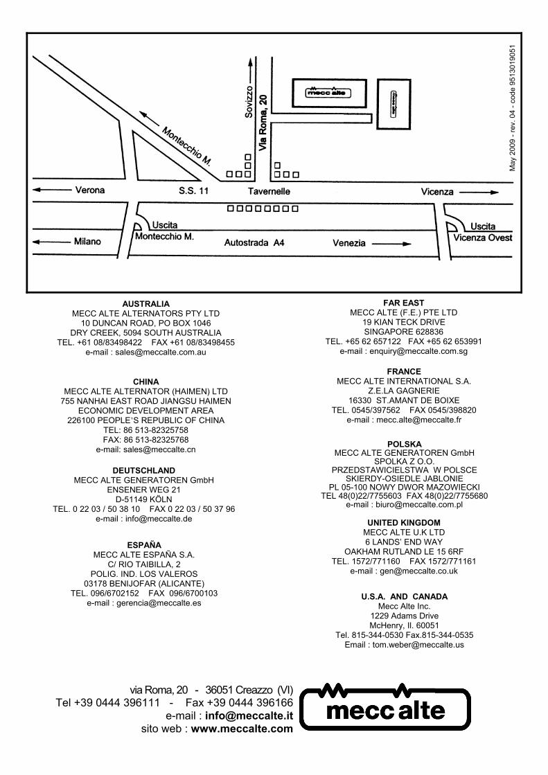
via Roma, 20 - 36051 Creazzo (VI)Tel +39 0444 396111 - Fax +39 0444 396166
e-mail : [email protected] web : www.meccalte.com
FRANCEMECC ALTE INTERNATIONAL S.A.
Z.E.LA GAGNERIE16330 ST.AMANT DE BOIXE
TEL. 0545/397562 FAX 0545/398820e-mail : [email protected]
ESPAÑAMECC ALTE ESPAÑA S.A.
C/ RIO TAIBILLA, 2POLIG. IND. LOS VALEROS
03178 BENIJOFAR (ALICANTE)TEL. 096/6702152 FAX 096/6700103
e-mail : [email protected]
FAR EASTMECC ALTE (F.E.) PTE LTD
19 KIAN TECK DRIVESINGAPORE 628836
TEL. +65 62 657122 FAX +65 62 653991e-mail : [email protected]
UNITED KINGDOMMECC ALTE U.K LTD6 LANDS’ END WAY
OAKHAM RUTLAND LE 15 6RFTEL. 1572/771160 FAX 1572/771161
e-mail : [email protected]
DEUTSCHLANDMECC ALTE GENERATOREN GmbH
ENSENER WEG 21D-51149 KÖLN
TEL. 0 22 03 / 50 38 10 FAX 0 22 03 / 50 37 96e-mail : [email protected]
AUSTRALIAMECC ALTE ALTERNATORS PTY LTD
10 DUNCAN ROAD, PO BOX 1046DRY CREEK, 5094 SOUTH AUSTRALIA
TEL. +61 08/83498422 FAX +61 08/83498455e-mail : [email protected]
U.S.A. AND CANADAMecc Alte Inc.
1229 Adams DriveMcHenry, Il. 60051
Tel. 815-344-0530 Fax.815-344-0535Email : [email protected]
POLSKAMECC ALTE GENERATOREN GmbH
SPOLKA Z O.O.PRZEDSTAWICIELSTWA W POLSCE
SKIERDY-OSIEDLE JABLONIEPL 05-100 NOWY DWOR MAZOWIECKI
TEL 48(0)22/7755603 FAX 48(0)22/7755680e-mail : [email protected]
May
200
9 - r
ev. 0
4 - c
ode
9513
0190
51
CHINAMECC ALTE ALTERNATOR (HAIMEN) LTD
755 NANHAI EAST ROAD JIANGSU HAIMENECONOMIC DEVELOPMENT AREA
226100 PEOPLE’S REPUBLIC OF CHINATEL: 86 513-82325758FAX: 86 513-82325768
e-mail: [email protected]