(I-00102) 1 DOWNLOAD THE LATEST INSTALL MANUALS AT …
18
8 February 2021 BD Universal Remote Mount Vacuum Brake (I-00102) 1 BD Engine Brake Inc. Plant Address: 33541 MacLure Rd. Abbotsford, BC, Canada V2S 7W2 U.S. Shipping Address: 1124 Fir Avenue, Blaine, WA 98230 U.S. Mailing Address: P.O. Box 231, Sumas, WA 98295 Phone: 604-853-6096 | Fax: 604-853-8749 | Internet: www.bddiesel.com DOWNLOAD THE LATEST INSTALL MANUALS AT www.bddiesel.com BD Remote Mount Vacuum Exhaust Brake Part Number Application 1037135 *1989-1998 Dodge Cummins 12V (Micro Switch) 4” Exhaust 1037136 1998-2002 Dodge Cummins 24V (DFIV) 4” Exhaust 1037143 1994-1997 Ford 7.3L Power Stroke 3.5” Exhaust 1037144 1994-1997 Ford 7.3L Power Stroke 4” Exhaust *1989-1993 Dodge trucks must purchase a separate throttle switch bracket (BD PN 1300535) Serial # Date Purchased Purchased from Installed by OWNER’S MANUAL – LEAVE IN GLOVE BOX
Transcript of (I-00102) 1 DOWNLOAD THE LATEST INSTALL MANUALS AT …

8 February 2021 BD Universal Remote Mount Vacuum Brake (I-00102) 1
BD Engine Brake Inc. Plant Address: 33541 MacLure Rd. Abbotsford, BC, Canada V2S 7W2
U.S. Shipping Address: 1124 Fir Avenue, Blaine, WA 98230 U.S. Mailing Address: P.O. Box 231, Sumas, WA 98295 Phone: 604-853-6096 | Fax: 604-853-8749 | Internet: www.bddiesel.com
DOWNLOAD THE LATEST INSTALL MANUALS AT
www.bddiesel.com
BD Remote Mount Vacuum Exhaust Brake
Part Number Application
1037135 *1989-1998 Dodge Cummins 12V (Micro Switch) 4” Exhaust
1037136 1998-2002 Dodge Cummins 24V (DFIV) 4” Exhaust
1037143 1994-1997 Ford 7.3L Power Stroke 3.5” Exhaust
1037144 1994-1997 Ford 7.3L Power Stroke 4” Exhaust
*1989-1993 Dodge trucks must purchase a separate throttle switch bracket (BD PN 1300535)
Serial #
Date Purchased
Purchased from
Installed by
OWNER’S MANUAL – LEAVE IN GLOVE BOX

8 February 2021 BD Universal Remote Mount Vacuum Brake 2
BD Engine Brake Inc. 1-800-887-5030 | https://www.bddiesel.com
TABLE OF CONTENTS
Generic Vacuum Brake Parts .................................................................................... 2
STANDARD REQUIRED PARTS – 40/60 ................................................................ 3
Welcome ................................................................................................................... 3
Options ..................................................................................................................... 4
Additional Required Parts ......................................................................................... 4
Valve Assembly Installation ...................................................................................... 5
Control Valve Assembly ............................................................................................ 6
Throttle Switch/DFIV Installation ............................................................................... 7
Ford Power Strokes (1994-97) ......................................................................... 7
DFIV Wiring Diagram ..................................................................... 7
Dodge 1994-1998 ............................................................................................ 9
Dodge 1988-1993 .......................................................................................... 10
Dodge 1998-2002 (24 valve engines) ............................................................ 10
Dodge DFIV Wiring Diagram (1998½ - 2002) .............................. 10
CRUISE CONTROL WIRING 2000-2002 6-speed MANUAL ONLY ........................ 12
DFIV Calibration (Only for kits using a DFIV module) ............................................. 13
Power and Toggle Switch ....................................................................................... 13
Exhaust Brake Routing Diagram ............................................................................. 14
Optional Manual Shifter (Push-Pull Style) ............................................................... 15
Testing .................................................................................................................... 15
Vacuum Brake Troubleshooting Guide ................................................................... 16
Operating Guidelines .............................................................................................. 17
Generic Vacuum Brake Parts

8 February 2021 BD Universal Remote Mount Vacuum Brake 3
BD Engine Brake Inc. 1-800-887-5030 | https://www.bddiesel.com
STANDARD REQUIRED PARTS – 40/60
Description Part Number Qty
1 Brake Valve 1137000 or
1137005 1 REQ’D
2 Spool Valve 1230001 1 REQ’D
3 Marmon Clamps 1100404 2 REQ’D
STEP #2 – THROTTLE SWITCH SELECTION 4 DFIV module 1321039 1
5 Micro Switch 1300420 1
STEP #3 – EXHAUST PIPE SIZE 6 Pipe Adapter 3” 1100300 2
7 Exhaust Seal Clamp 3” 1100730 2
8 Pipe Adapter 3.5” 1100350 2
9 Exhaust Seal Clamp 3.5” 1100735 2
10 Pipe Adapter 4” 1100400 2
11 Exhaust Seal Clamp 4” 1100740 2
STEP #4 – MAIN SWITCH SELECTION 12 Toggle Switch 1300201 1
13 Push / Pull Switch 5/8” 1300210 1
14 Push / Pull Switch 3/4” 1300211 1
15 Rocker Switch 5/8” 1030900 1
16 Rocker Switch 3/4” 1030910 1
17 Switch Cover (toggle only) 1302250 1
1137005 brake kit uses actuator 1133065 (65 pound spring) 1137000 brake kit uses actuator 1133060 (60 pound spring)
Welcome Thank you for purchasing a BD Engine Exhaust Brake. This manual is to aid you with your installation and operation of your braking unit. We strongly suggest that you fill out the information on the front page and retain this manual for any future reference.

8 February 2021 BD Universal Remote Mount Vacuum Brake 4
BD Engine Brake Inc. 1-800-887-5030 | https://www.bddiesel.com
Options
Description Part #
Manual Transmission Shifter Switch Kit 1300210 / 1030900 AutoLoc Convertor Lock-up Kit 1030390 Torqloc Convertor Lock-up Kit 1030395 Brake Pressure Gauge Kit 1030050 HD Exhaust Valve Springs 1030060
Additional Required Parts To install the microswitch on 1989-1993 Dodge trucks requires a microswitch bracket that is not supplied in this kit. BD part number 1300535.

8 February 2021 BD Universal Remote Mount Vacuum Brake 5
BD Engine Brake Inc. 1-800-887-5030 | https://www.bddiesel.com
Valve Assembly Installation Inspect the vehicles exhaust system between the engine and the muffler. A straight section of pipe will have to be cut to accommodate the exhaust brake assembly - approximately 7 to 8 inches long. On 1994 or newer Dodges, the valve is mounted before the Catalytic Converter, on Ford and Chev/GM vehicles with Catalytic Converters, the valve is mounted between the Cat and muffler. There should be no exhaust-flex pipe between the engine and exhaust brake valve, however, flex pipe is okay after the valve. Cut the exhaust pipe in a straight section of the system, you will need to weld one of the supplied adapters to the section of pipe coming from the front of the vehicle’s engine.
Weld
Here
Use SS
Band ClampUse V
Clamp
Rear of Truck
Temporarily mount the exhaust valve assembly on the adapter, with the supplied V clamp on the valve sliding. From here, cut off as much of the remaining exhaust needed to accommodate the valve and remaining adapter. Remove the exhaust valve assembly and clamp, or weld the rear adapter to the other section of exhaust pipe. Mount the exhaust valve assembly using the two supplied V-clamps, with the vacuum cylinder pointing away from the engine, and tighten the nuts and bolts. NOTE: The arrow on the Exhaust Valve casting indicates exhaust flow, which should be pointed towards the rear of the vehicle (Figure 1).
Plastic button must be facing down.

8 February 2021 BD Universal Remote Mount Vacuum Brake 6
BD Engine Brake Inc. 1-800-887-5030 | https://www.bddiesel.com
Control Valve Assembly The control valve assembly has two hoses attached to it. Push the shorter piece onto the barbed fitting on the front cap of the vacuum cylinder on the exhaust valve assembly (see Diagram 1) and push the longer piece onto the barb fitting on the back cap (Red). With the hoses now attached, locate or drill a new hole on the inner frame rail to mount the control valve assembly within reach of the hoses. Existing holes or new holes will have to be drilled out to 5/16”. Mount the control valve assembly to the frame using the long bolt, spacer and nut provided (Dia. 2). A good ground must be made when bolting bracket to frame rail. There is a loose section of plastic hose that came included with the spool valve kit with a yellow plastic vent filter on it. Attach this to the spool valve (#3) and run to a dry location inside your cab. This vent prevents moisture from entering inside the control (spool) valve. NOTE: If the vehicle has a vacuum assisted hydraulic brake booster or the vacuum pump is located on the driver side, then run the hose and wire along a cross member and up the driver’s side frame rail. In the engine compartment, locate the hose coming from the vacuum pump on the engine or to the vacuum assisted hydraulic Brake Booster. (On newer Chevrolets, the Air Conditioner Pump will have to be unbolted from its bracket and pushed off to one side.) Push the plastic tee (supplied in Application Kit) onto the hose coming from the Control Valve Assembly, and run hose to Vacuum Pump or Brake Booster. Cut the outlet hose of the vacuum pump or brake booster, no closer than 1” from the outlet fitting. Push both ends of the hose onto the plastic tee. Secure the hose with tie wraps and keep it clear of moving or heated parts. Run the wire coming from the Control Valve Assembly though the fire wall (except Dodge and Cummins Trucks & Motorhomes) and to the Throttle Switch; using an electrical connector, hook up wire to the top screw on switch, or on Ford Power Strokes, free terminal (#87a) on relay. For Dodge and Cummins Trucks & Motorhomes, run wire over to Throttle Switch, cut wire and connect to the top terminal with an electrical connector. See microswitch/DFIV wiring diagrams in this manual for more information.
8 February 2021 BD Universal Remote Mount Vacuum Brake 7
BD Engine Brake Inc. 1-800-887-5030 | https://www.bddiesel.com
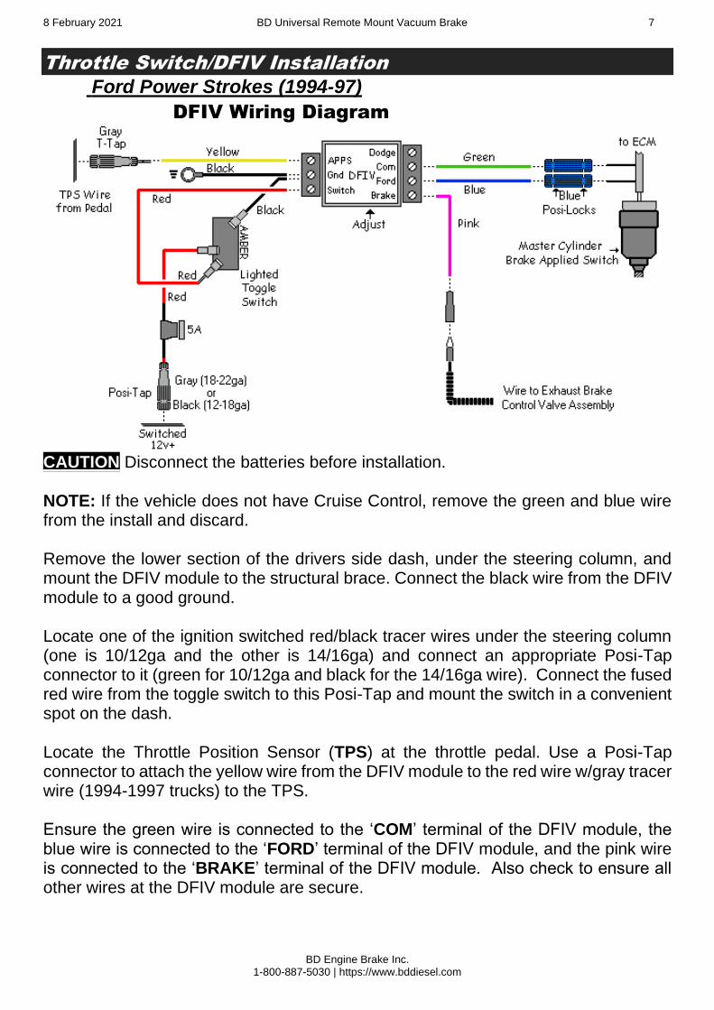
Throttle Switch/DFIV Installation
Ford Power Strokes (1994-97)
DFIV Wiring Diagram
CAUTION Disconnect the batteries before installation. NOTE: If the vehicle does not have Cruise Control, remove the green and blue wire from the install and discard. Remove the lower section of the drivers side dash, under the steering column, and mount the DFIV module to the structural brace. Connect the black wire from the DFIV module to a good ground. Locate one of the ignition switched red/black tracer wires under the steering column (one is 10/12ga and the other is 14/16ga) and connect an appropriate Posi-Tap connector to it (green for 10/12ga and black for the 14/16ga wire). Connect the fused red wire from the toggle switch to this Posi-Tap and mount the switch in a convenient spot on the dash. Locate the Throttle Position Sensor (TPS) at the throttle pedal. Use a Posi-Tap connector to attach the yellow wire from the DFIV module to the red wire w/gray tracer wire (1994-1997 trucks) to the TPS. Ensure the green wire is connected to the ‘COM’ terminal of the DFIV module, the blue wire is connected to the ‘FORD’ terminal of the DFIV module, and the pink wire is connected to the ‘BRAKE’ terminal of the DFIV module. Also check to ensure all other wires at the DFIV module are secure.
8 February 2021 BD Universal Remote Mount Vacuum Brake 8
BD Engine Brake Inc. 1-800-887-5030 | https://www.bddiesel.com
Run the pink, green and blue wires through a grommet on the firewall making sure all wires are secure and away from moving objects and heat sources. Go to page 11 and follow the instructions to calibrate the DFIV module. Cruise Control Disable Wiring Locate the factory black w/yellow tracer wire at the cruise control disable (Brake Applied) switch located on the brake master cylinder and expose the wiring approximately 4-6 inches from the switch to allow for a good length to work with. This wire may be a different color in various applications. If there is no black w/yellow wire going to this switch, then use a test light to check which wire changes state (power to no power) when the brake pedal is applied. Cut the black w/yellow tracer wire (BK/Y), then strip both ends and attach a separate blue Posi-Lock connector on each end of the cut wire. Run the green and blue wires that were brought through the firewall to the Brake Applied Switch at the brake booster and cut off any excess. Attach these wires to the two blue Posi-Lock connectors that you have just installed to the Black wire w/Yellow tracer.

8 February 2021 BD Universal Remote Mount Vacuum Brake 9
BD Engine Brake Inc. 1-800-887-5030 | https://www.bddiesel.com
Dodge 1994-1998 At the throttle pedal, locate the nuts on the large aluminum bracket just up from and to the left of the pedal. Remove the lower nut and loosen off the top nut. Locate the larger microswitch bracket (1300533) included in the control kit. Slide the top of the bracket under the upper loosened nut and the lower stud through the hole. Reinstall the lower nut but don’t tighten them yet. Loosely install the microswitch into the microswitch bracket if not already done. Do not tighten yet as it will need to be adjusted.
Locate the small pedal bracket (1300532). Position this bracket over the throttle pedal arm so that it will line up with the microswitch button as shown in the diagram below.
Ensure sufficient clearance between the long Micro Switch Bracket and the throttle pedal by sliding the bracket as far to the left as possible, to eliminate any possibility of pedal catching on bracket. Adjust both brackets so that the small bracket on the pedal arm will depress the button on the Micro Switch when the pedal is in the idle position.
When satisfied, mark and drill the two holes on the pedal arm and screw or pop rivet pedal bracket to arm. Tighten the nuts for the aluminum bracket and do final adjustments to Micro Switch bracket on the aluminum bracket. Periodic adjustment to the Throttle Switch might be needed to maintain proper contact with bracket on throttle pedal. Connect a length of the supplied wire from the “com” terminal on the micro switch to the red wire on the spool valve. Run another length of wire from the “NO” (Normally Open) terminal through the firewall. This will be connected later. NOTE: If the throttle return springs are weak, they may not be strong enough to depress the button on the micro switch. In this case the springs will have to be replaced or additional springs added. Also, worn throttle linkage can make it difficult to get the micro switch to activate consistently.

8 February 2021 BD Universal Remote Mount Vacuum Brake 10
BD Engine Brake Inc. 1-800-887-5030 | https://www.bddiesel.com
Dodge 1988-1993 The Throttle Switch Bracket mounts behind the throttle linkage using the two bolts used for mounting the throttle linkage to the engine (Diagram 6). On all years, if throttle return spring(s) are weak, another spring may have to be installed. This bracket is not included in this kit. Order BD #1300535. On all microswitch installations, adjustment of the microswitch is needed. Manually move the linkage back and forth to make sure the proper activation to the throttle switch is occurring. The throttle switch may have to be adjusted on occasion. NOTE: With mechanical injection pump systems, the linkage is moved during cruise control and/or fast idle operations, so the brake will not be activated during these occurrences.
Dodge 1998-2002 (24 valve engines)
Dodge DFIV Wiring Diagram (1998½ - 2002)
Mount the DFIV module in a secure location under the dash using the cable ties provided. Route the pink and yellow wires through the firewall into the engine bay,

8 February 2021 BD Universal Remote Mount Vacuum Brake 11
BD Engine Brake Inc. 1-800-887-5030 | https://www.bddiesel.com
there is usually an existing grommet in the firewall behind the brake pedal which can be used for this. Attach the black ground wire to the “Gnd” terminal on the DFIV and attach the ring terminal to a good ground. Route the Yellow wire from the DFIV module along the driver side of the engine to the throttle linkage and APPS Sensor. Remove the cover of the throttle linkage then locate and disconnect the wiring connector for the APPS. NOTE: This connector is located on the underside of the throttle linkage assembly and is in a difficult position. Open the loom and locate the Light Blue w/Black wire and install a supplied Posi-Tap™ to it. Connect the Yellow wire from the DFIV Module to this Posi-Tap™ and reconnect the APPS connector then reinstall the throttle linkage cover.

8 February 2021 BD Universal Remote Mount Vacuum Brake 12
BD Engine Brake Inc. 1-800-887-5030 | https://www.bddiesel.com
CRUISE CONTROL WIRING 2000-2002 6-speed MANUAL ONLY
This step is only for 2000-2002 manual transmission trucks with cruise control. All other vehicles do not need the cruise control wires connected as they use a vacuum servo for cruise control rather than an internal program in the ECM. If your vehicle does not have cruise control you can remove the blue and green wires from the DFIV and discard them. Skip this step and proceed to Switch Installation.
To obtain access to the Cruise Control wiring harness remove the lower steering column panel by removing the mounting screws and unsnapping the panel from the instrument panel.
Under the dash running vertical by the left of the steering column, locate the smaller wiring harness that runs out of the main harness.
Remove some of the black electrical tape to gain access to the smaller wire bundle.
***DANGER***
THERE IS A BLACK WIRE WITH A TWISTED LIGHT BLUE/GREEN TRACER DO NOT CONNECT OR TEST THIS WIRE AS IT IS CONNECTED TO THE AIR BAG AND THE BAG MAY DEPLOY CAUSING DAMAGE AND/OR INJURY
***DANGER***
Remove some of the black electrical tape from the small bundle to gain access to the small Black wire with Light Blue tracer and install a Posi-Tap™ to it. Insert the Blue wire from the DFIV module into this connector. In this same wiring harness, locate the Red wire with Light Green tracer and install another Posi-Tap™. Insert the Green wire from the DFIV module into this connector.

8 February 2021 BD Universal Remote Mount Vacuum Brake 13
BD Engine Brake Inc. 1-800-887-5030 | https://www.bddiesel.com
DFIV Calibration (Only for kits using a DFIV module) Ensure the connections of the corresponding wires to the DFIV Control Module are correct as shown in the wiring diagram. To achieve the correct setting for the activation of the exhaust brake in relation to the throttle pedal the DFIV Module must be calibrated for your vehicle. Connect one end of a test light to the “BRAKE” terminal of the DFIV module and the other end to a good ground. With the throttle at idle, start the engine and turn on brake switch. Then, using a small flat bladed screwdriver, turn the small adjusting screw in the DFIV Module counterclockwise or clockwise until the test light JUST turns on. CAUTION: THE ADJUSTING SCREW IS A MICRO-SWITCH THAT IS VERY DELICATE, SO TURN USING SMALL ADJUSTMENTS. Test by revving up the engine to approximately 1200 RPM and releasing the throttle. As the accelerator pedal is applied the test light should turn off just before the engine starts to rev, indicating proper calibration of the DFIV Module with the APPS. Then the test light should activate again when the throttle pedal returned to idle. If not, readjust the DFIV Module so that it does. Reinstall lower dash cover.
Power and Toggle Switch Mount the toggle switch in a convenient and secure location on the dash. Locate a 12v ignition switched source (fuse panel or wire), then connect the in-line fuse holder to the source line or use the fuse tapper (Diagram 7).
This power wire should be connected to the middle terminal of the toggle switch. Ground the black wire from the upper switch terminal marked amber. Connect the lower switch output terminal to the middle position on the throttle micro switch or to the DFIV “Switch” terminal. Connect the remaining terminal on the micro switch to the exhaust brake control valve you mounted earlier. Route this wire away from any heat sources or moving parts.

8 February 2021 BD Universal Remote Mount Vacuum Brake 14
BD Engine Brake Inc. 1-800-887-5030 | https://www.bddiesel.com
Exhaust Brake Routing Diagram
Fa
cto
ry v
acu
um
lin
e
Ve
nt
line
filt
er
(Mo
un
t in
dry
lo
ca
tio
n)
Direction
of e
xha
ust flow
Te
st
butt
on
fa
ce
s d
ow
n
Bra
ke
activa
tio
n w
ire
(T
o D
FIV
or
mic
rosw
itch
)
Gro
und
Sp
oo
l va
lve
flo
ws c
risscro
ss w
he
n n
ot e
ne
rgiz
ed
, and f
low
s d
irectly a
cro
ss w
he
n e
ne
rgiz
ed.
Ap
ply
ing v
acu
um
to t
he r
ed e
nd o
f th
e c
ylin
de
r w
ill
rele
ase th
e b
rake. A
pp
lyin
g v
acu
um
to t
he b
lue e
nd
w
ill a
pp
ly th
e b
rake.

8 February 2021 BD Universal Remote Mount Vacuum Brake 15
BD Engine Brake Inc. 1-800-887-5030 | https://www.bddiesel.com
Optional Manual Shifter (Push-Pull Style) Mount the push/pull switch on the shifter lever (Diagram 10), using the switch clamp, and secure the cable on to the lever. NOTE: Keep cable away from spots where it could get pinched during shifting. Strip the ends of the wires and attach male blade connectors to each. Slip off the Red wire from Toggle Switch and attach to Black wire of Manual Shifter Switch cable, and, slip off the Yellow wire from Toggle Switch and attach to White wire of cable. Discard Toggle Switch and its black wire. Attach the Yellow wire to the middle terminal of Throttle pedal Switch or the 12V Switched input of the DFIV.
Testing Start up the engine and turn the toggle switch on to make sure the brake activates. Depress the throttle pedal and let up on it to check that operation of the throttle switch, allowing the brake to engage when the throttle is in the resting/idle position. Using a standard pressure gauge, follow the list below for proper setting, with the engine running at idle and brake turned on. Install the pressure gauge into the NPT port on the side of the exhaust brake casting to measure exhaust pressure.
Vehicle Lbs. Pressure @ Idle
Chevy 6.2/6.5L & Ford 6.9/7.3L 32lbs. 8-10 lbs.
Ford Powerstroke & Dodge Cummins 40lbs. 10-12 lbs.
Dodge Cummins w/ 60lb. exhaust springs 60lbs. 18-20 lbs.
If the brake pressure does not fall within these limits, please call the BD
Engine Brake technical hotline at (800) 887-5030.
Be sure to test the cruise control disconnect system (where applicable) while test-driving. Set the cruise at a safe speed and then turn the exhaust brake on, which should turn the Cruise Control off right away. If the cruise control does not disengage right away, then turn the exhaust brake off immediately. If the cruise control did disengage, then turn the exhaust brake off and hit the resume function on the cruise control switch to see if the cruise will re-engage.

8 February 2021 BD Universal Remote Mount Vacuum Brake 16
BD Engine Brake Inc. 1-800-887-5030 | https://www.bddiesel.com
Vacuum Brake Troubleshooting Guide This guide assumes that your exhaust brake system is using a DFIV. If you system uses a microswitch for throttle activation, the operation of the spool valve is the same as with the DFIV. Always check to make sure the vehicles vacuum system is operating correctly and is free of leaks. Most systems will produce approximately 15in/Hg (inches of mercury), or 7.5psi absolute, at sea level.
When I let off the throttle nothing happens.
No Yes
Check vacuum supply to the spool valve. Is the DFIV powering the “brake” output wire when the throttle is at idle and brake switch and ignition are both on?
Check that DFIV has good power, ground and throttle signal. Check DFIV adjustment. If all these things check out, but the DFIV won’t power the “brake” wire, the DFIV is likely faulty. Also check for a good ground at the spool valve.
Check that when spool valve is powered it switches vacuum output from the hose going to the rear of the vacuum cylinder to the hose going to the front of the cylinder (the end that the rod comes out of).
The brake comes on but there’s little or no holdback
No Yes
Check that torque converter is staying locked up. If it is not, the engine RPM will fall to idle when the throttle is released. Check off-idle brake backpressure. Are you getting maximum allowable backpressure? (See backpressure chart)
Check for exhaust leaks. A small leak can result in a significant decrease in brake backpressure. Check for vacuum leaks.
Try down shifting more aggressively. More RPM will give more holdback. Vacuum systems will decrease in effectiveness with an increase in altitude. For example at 5000ft a 60psi brake will only make about 50psi exhaust backpressure. Transmission or torque converter could be slipping internally.
Everything seems to work, but the brake valve won’t close.
No Yes
Check that vacuum is reaching the front hose (near where the rod comes out) of the brake cylinder.
Spool valve stuck, plugged or faulty. Clean or replace as required.
Cylinder or brake valve are seized. Remove the clevis pin on the end of the cylinder rod & see if the valve lever can be moved freely.
The valve lever can be moved freely.
Try dismounting the brake & cleaning the carbon out of it. If this does not work the brake valve will need to be replaced.
The cylinder is stuck and will need to be replaced.
Problem Solution
Air compressor runs in short bursts and brake is slow to apply.
There is a restriction in the air system, normally in the regulator or air solenoid. Remove the fittings from the regulator and air solenoid, you will likely find some corrosion or debris caught in them. Clean this out with a pick, small brush, compressed air and WD40 or similar lubricant.
Air compressor runs continually. Pump relay is likely stuck on. Check operation of relay & replace as required.
Brake is slow to release. Debris or corrosion is restricting the quick release valve or air solenoid. Clean as required. Air solenoid could be too far from brake.

8 February 2021 BD Universal Remote Mount Vacuum Brake 17
BD Engine Brake Inc. 1-800-887-5030 | https://www.bddiesel.com
Operating Guidelines Thank you for taking interest in the BD Engine Exhaust Brake. As a driver, you probably already know the need for extra braking power that your vehicle requires on the hills and long grades. With loads being towed behind you, the extra push when slowing down or maintaining speed on downward grades can prove to be a great strain on your vehicles chassis’s braking system, even to the point of “burn-up”. These guidelines were designed to offer you a better understanding of the benefits of exhaust brakes and are partly based upon material developed by the U.S. Department of Transportation National Highway Traffic Safety Administration. The emphasis on today’s vehicles is to give the consumer a product that can give them usable power with fuel efficiency. But, in the transition, the vehicles have lost their natural braking power, making it easier for the vehicle to continue to roll and harder to stop. Of course, this gets more noticeable with the increase of weight, on or behind the vehicle. This is where an exhaust brake becomes a useful tool for increasing the driveline drag of the vehicle without the use of the chassis’s brakes. A tool, which with maximum or even occasional use can reduce wear on chassis’ braking parts and at the same time increase safety. The BD Exhaust Brake can be used to help maintain a controlled vehicle speed on a downward grade, as well as slowing the vehicle down for such times as turns or exit ramps, without you using your chassis’s brakes. The exhaust brake cannot be used as a parking brake or will not bring your vehicle to a complete stop. By using a BD Exhaust Brake, the life and effectiveness of your chassis’s brakes will increase. This is because of the decreased use of the chassis’s brakes in situations like hills, the wear factor is reduced and there is less opportunity for your chassis’s brakes to heat up which would reduce the efficiency. When you ride your chassis’s brakes, make hard stops or have poorly adjusted brakes, this creates high temperatures and as your brakes get hotter, the more chance there is for fade or failure. When the toggle switch is turned to the “On” position, the valve is activated every time the driver takes their foot off of the throttle pedal. When the driver puts pressure back on the throttle pedal, the throttle switch is deactivated and the valve opens again. Exhaust brakes are designed to operate with the throttle at idle, not to be used in conjunction with cruise controls, and not designed to aid in gear shifting. Such cases could cause damage to engine and/or the exhaust brake. Incorporated with the BD Exhaust Brake, there is a pressure regulating system that will control the created backpressure. If the backpressure reaches the set limit, the exhaust valve will open slightly to relieve the excess pressure.

8 February 2021 BD Universal Remote Mount Vacuum Brake 18
BD Engine Brake Inc. 1-800-887-5030 | https://www.bddiesel.com
The brake pressure at idle is required to be checked and adjusted at time of installed, two weeks after installed, and on a regular twice a year interval. For Ford IDI and Chevy vehicles adjust the brake pressure to 8-10lb at idle; and Ford PowerStrokes, adjust to 10-12lb at idle. On Dodge 6BTA (1989-98) with the stock exhaust valve springs, adjust the idle pressure to 10-12lb at idle, and if the heavy duty valve springs have been installed, adjust idle pressure to 18-20lb at idle. Dodge ISB (1998-up), adjust idle pressure to 18-20lb at idle. Never adjust the brake to the 60 lb. setting on an engine that has not had the heavy-duty engine exhaust valve springs installed first. With the normal mounting position of the Control Valve Assembly being on the frame rail, it would make it exposed to water if driven through rivers, creeks, or deep bodies of water. If the Exhaust Brake is being used during these situations, water could be sucked through the venting filter and eventually into the Vacuum Cylinder, damaging booth. For the best prevention of this damage, do not operate the brake during these occurrences. The best scenario for exhaust braking is when going down hill, select a gear that lets you maintain a constant speed with little or no use of the chassis’s brakes, or the same gear that would be used to go up the same grade of hill. This also depends on the weight, load or road conditions that the vehicle will come upon. So, in summary, by using the BD Exhaust Brake, you reduce the need for use of your chassis’s brakes in situations where you need to slow down or maintain (i.e. hills, off ramps, approaching speed changes or traffic lights). By reducing the use of your chassis’ brakes, in these situations, the heat build up is reduced, as well as wear and damage to linings and drums. And, when you reduce these factors, you save your chassis’s brakes for when you really need them (i.e. for stopping or emergencies). The BD Exhaust Brake is not a substitute for your chassis’s brakes and, cannot correct or compensate for poorly maintained or misadjusted brakes. But, when you need to slow down or maintain a constant speed, the BD Exhaust Brake will be a valuable and effective tool. Exhaust Brakes are more efficient at preventing than correcting an over speed condition. To increase the life of your exhaust brake we recommend daily operation. This could simply be switching it on and off a couple times a day. This will prevent the butterfly from sticking due to carboning up. Thank you and happy motoring, BD Engine Brake, Inc.