The 74ZC has two manuals - Chimney Sweep Columbusnewbucksweep.com/BuckStoveImages/Wood and Coal...
67
The 74ZC has two manuals: 1. The Model 74 Stove manual 2. The 51ZC Cabinet manual (covering 51ZC & 74ZC installations) For your convenience, these two manuals have been combined into one file to make it easier to download and review. If you wish to have ONLY the cabinet manual, please download the 51ZC cabinet manual from the stove manuals download page. Thank you!
Transcript of The 74ZC has two manuals - Chimney Sweep Columbusnewbucksweep.com/BuckStoveImages/Wood and Coal...

The 74ZC has two manuals: 1. The Model 74 Stove manual 2. The 51ZC Cabinet manual (covering 51ZC & 74ZC installations)
For your convenience, these two manuals have been combined into one file to make it easier to download and review. If you wish to have ONLY the cabinet manual, please download the 51ZC cabinet manual from the stove manuals download page. Thank you!

The following manual is the Model 74 Stove manual…

FIREPLACE INSERT & FREESTANDING
MODEL 74 NON-CATALYTIC UNIT
FEATURES PREPARATIONS INSTALLATION
OPERATION MAINTENANCE SAFETY
SAFETY NOTICE
IF THIS HEATER IS NOT PROPERLY INSTALLED, A HOUSE FIRE MAY RESULT. FOR YOUR SAFETY, FOLLOW THE INSTALLATION INSTRUCTIONS. CONTACT THE AUTHORITY HAVE JURISDICTION ( SUCH AS MUNICIPAL BUILDING DEPARTMENT, FIRE DEPARTMENT, FIRE PREVENTION BUREAU, ect.) SHOULD BE CONSULTED BEFORE INSTALLATION TO DETERMINE THE NEED TO OBTAIN A PERMIT. KEEP THESE INSTRUCTIONS FOR FUTURE USE. TESTED AND LISTED BY: ITS/WARNOCK HERSEY, MIDDLETON, WI
MANUFACTURED BY NEW BUCK CORPORATION - SPRUCE PINE, NC 28777
Revised January 2010
Buck Stove

TABLE OF CONTENTS
Important Instructions ......................................................................................................... 2 SECTION I: Introduction ................................................................................................... 3 Type of wood and loading procedures …………………………………….. ……………..3 SECTION II: Masonry Insert Installation ........................................................................... 4 Installation Preparation-Fireplace ....................................................................................... 5 Mounting the Trim Panels .................................................................................................. 7 SECTION III: Pre-Fab Insert Installation ......................................................................... 10 SECTION IV: Residential Freestanding Installation ........................................................ 11 Clearances To Combustibles Freestanding Without Close Clearance Shields and Using Single Wall Pipe…………………………………………………….. 19 Residential / Mobile Home Double Wall or Shielded Single Wall Connector With Close Clearance Shields……………………….……………………….20 Residential / Mobile Home Double Wall or Shielded Single Wall Connector Without Close Clearance Shields……………………….…………………....21 Installation of Close Clearance Shields (Optional) ........................................................... 22 Alcove Installation Double or Shielded Single Wall Connector With Close Clearance Shields ............................................................................................................. 23 SECTION V: Freestanding Mobile Home Installation ..................................................... 24 SECTION VI: Wood Heater Safety .................................................................................. 30 SECTION VII: Operation ................................................................................................. 31 SECTION VIII: Troubleshooting ..................................................................................... 32 Warranty………………………………………………………………………………… 34

INSTALLATION, OPERATION, AND MAINTENANCE INSTRUCTIONS
MODEL 74
BEFORE INSTALLING YOUR NEW BUCK STOVE, READ THE ENTIRE INSTRUCTION MANUAL
IMPORTANT INSTRUCTIONS
WARNING THESE UNITS GENERATE A LOT OF HEAT, SO TREAT THEM WITH CARE. HOT WHILE IN OPERATION! KEEP CHILDREN, CLOTHING AND FURNITURE AWAY. CONTACT MAY CAUSE SKIN BURNS.”DO NOT USE CHEMICALS OR FLUIDS TO START THE FIRE.” “DO NOT BURN GARBAGE OR FLAMMABLE FLUIDS.” DO NOT CONNECT TO ANY DISTRIBUTION DUCT OR SYSTEM. READ ALL INSTRUCTIONS BEFORE INSTALLING AND USING THE APPLIANCE. FAILURE TO FOLLOW INSTRUCTIONS MAY RESULT IN PROPERTY DAMAGE, BODILY INJURY, OR EVEN DEATH. SAVE THESE INSTRUCTIONS FOR FUTURE REFERENCES.
The New Buck Corp. non-catalytic Model 74 has been tested by ITS, Warnock Hersey to ANSI/UL Standards 1482.
Install and operate your unit according to instructions provided in this manual. Local building codes may apply; therefore, contact your local building inspector or fire marshal for necessary installation requirements and permits which may go beyond these instructions. Contact your insurance company for coverage and installation inspection.
If MODEL 74 is installed in a mobile home: “DO NOT INSTALL IN SLEEPING ROOMS.”
NOTE: When burning any unit or appliance that combust fuel for heat, such as coal, oil, wood or natural and (L.P.) liquid petroleum gas. We highly recommend the use of smoke and carbon monoxide detectors in your home.
The Model 74 is approved for use in specified Zero Clearance fireplaces (ZCF’s).
Examine the masonry fireplace and chimney prior to installation of the fireplace accessory to determine that the construction meets the minimum fireplace construction requirements illustrated in the instructions, that it is free from cracks, loose mortar, creosote deposits and other blockage, or other signs of deterioration.
CAUTION DO NOT USE MORE THAN ONE STOVE TO A CHIMNEY. DO NOT USE A FLUE INTENDED FOR A GAS APPLIANCE.
Page 2

CAUTION YOUR CHIMNEY MUST BE CORRECTLY SIZED. A CHIMNEY THAT IS TOO SMALL OR LARGE IN DIAMETER, OR TOO SHORT, CAN CAUSE YOUR STOVE TO SPILL SMOKE WHEN THE DOOR IS OPENED.
SECTION I
INTRODUCTION Your new MODEL 74 is a non-catalytic unit designed to meet the most stringent emissions standards without the use of a catalytic combustor. This effect is achieved through the use of secondary air which is mixed with primary air in the unit’s firebox. For peak performance, we suggest the use of natural seasoned hard wood, loading wood length way from front to rear. NOTE: Soft woods such as pine, create more creosote, clogging of chimney, and produce a less efficient burn performance. You should not burn trash or garbage, artificial or paper logs, gift wrapping, treated or painted wood or any type of coal, or flammable fluids. The primary air, which is controlled by the user, burns the wood. Secondary air is admitted into the firebox through the secondary air tubes at the top of the firebox. This secondary air burns the impurities in the smoke released from the initial wood burning. The temperature necessary for this combustion is maintained through the firebrick refractory. If any more technical information is necessary, contact your local dealer. Under specific test conditions this heater has been shown to deliver heat at rates ranging from approximately 11,800 to 40,900 BTU/HR. This unit may also be used with optional room air blower. To order optional motor assembly you must specify the stove model number and give the following part number: *Model 74: Motor Assembly—MA 5126715 For operation and use of this electrical assembly, see instructions provided with the motor assembly kit.
Page 3

SECTION II
MASONRY INSERT INSTALLATION The Model 74 may be installed using an all masonry fireplace built in accordance with the Uniform Building Code and National Fire Protection Association (NFPA). The first step in this type of installation is to determine the acceptability of the fireplace and chimney for use with a woodstove. Both the construction and condition of the fireplace are important consid-erations when installing a woodstove. The chimney should extend at least 3' above the roof and at least 2' above any point of the roof within 10'.
CAUTION
REMEMBER TO HAVE YOUR CHIMNEY INSPECTED FOR LEAKS AND BLOCKAGE BEFORE YOU INSTALL YOUR STOVE. ”DO NOT CONNECT THIS UNIT TO A CHIMNEY FLUE SERVING ANOTHER APPLIANCE.”
MINIMUM CLEARANCE MASONRY INSERT
A. Side Wall Combustible B. Front Floor Protector C. Side Floor Protector D. Side Wood Trim E. Top Wood Trim F. Mantel or Brackets
16" 20" 8" 10" 10" 24"
MODEL 74
1. The hearth must be of masonry construction and must extend a minimum of 20" in front of
the firebox opening and a minimum of 8" to either side of the firebox opening. 2. If there is not minimum hearth protection from the front of the firebox opening and the front of the masonry hearth, a floor protector must be used in front of the hearth to protect combustible materials. The floor protector must be 3/8" minimum thickness non- combustible material or equivalent.(See Page 12,13.)
F
B
A
E
C
D
Page 4

POSSIBLE TOOLS NEEDED FOR INSTALLATION If you decide to install your own stove, there are several hand tools you may need to do the job. If you do not already have them, they are readily available at most hardware stores. Caulking gun Large adjustable wrench (may not be needed) Drop cloths or newspapers Vacuum cleaner or whisk broom Flashlight 1 tube of RTV silicone, Code 103 or 106, or high temperature rubber cement rated between 450o F- 600o F 7/32" drill bit and drill Socket/Rachet Set
INSTALLATION PREPARATION Fireplace: 1. Locate furniture and other materials away from the front of the fireplace to allow free access
to the fireplace. 2. Cover the hearth and adjacent floor areas with a drop cloths to protect from soiling or
marring the surface. 3. Remove the existing fireplace damper plate. 4. Thoroughly clean the fireplace of ashes and soot. 5. Check the chimney and smoke chamber for excessive buildup of creosote or soot. Also,
check for obstructions, such as bird’s nests. If the chimney is excessively dirty, clean it, or have someone clean it professionally BEFORE installing or using the room heater.
6. If the fireplace has an ash dump or outside air provision, these must be sealed off with metal or tightly packed non-combustible insulation to prevent cold air from entering the fireplace chamber.
MASONRY INSERT INSTALLATION INSTALLATION OPTIONS
This unit (appliance) may be installed into an all masonry fireplace, built in accordance with the Uniform Building Code and the National Fire Protection Association (NFPA 211). NOTE: Check with local building officials for any permits required for installation of this unit and notify your insurance company before proceeding with installation In some cases such as improperly drawing fireplaces , oversize flue liners, or to meet codes in certain areas it is recommended that one of the flowing procedures be followed. A. A Chimney Connector be installed from the appliance flue exit through the damper and a air-tight face seal. See option (A) page 6. B. A listed Direct Connect be installed from the appliance flue exit through the damper into the first section of the flue liner with air-tight seal. See option (B) page 6. C. A Positive Connect be installed from the appliance flue exit continuing up through the entire chimney and exiting at the top of the chimney. See option (C) page 6.
Page 5

OPTION (B)
REMOVE DAMPER OR WIRE IT OPEN
AIRTIGHT INSULATED CLEAN-
BLOCK-OFF PLATE OR DAMPER ADAPTER
SEAL TRIM PANELS WITH INSULATION OR HIGH TEMPERATURE CAULK
STAINLESS STEEL CHIMNEY CONNEC-TOR MUST EXTEND 1’ PAST THE BLOCK-OFF PLATE OR TO THE FLUE LINER
NOTE: Follow installation instruction with Direct Connection Kit. (Kit sold separately)
SAFETY NOTICE
If this appliance is not properly installed, a house fire may result. For your safety, follow the installation directions. Contact local building or fire officials about restrictions and installation inspection requirements in your area.
STARTER PIPE
SEAL TRIM PANELS AND UNDER FRONT OF STOVE UNIT WITH INSULATION OR HIGH TEMPERATURE CAULK
OPTION (A)
REMOVE DAMPER OR WIRE IT OPEN
AIRTIGHT INSU-LATED CLEAN-OUT
NOTE: New Buck Corporation grants no warranty, implied or stated, for the installation or maintenance of your appliance, and assumes no responsibility of any consequential damage
OPTION (C)
NOTE: Follow installation instruction with Positive Connection Kit. (Kit sold separately)
TRIM PANELS
CAP(PREVENTS WATER FROM ENTERING)
FLUE LINER
THE LINER MUST BE STAINLESS STEEL CONNEC-TOR OR FLEXIBLE VENT. FOLLOW THE LINER MANU-FACTURE’S IN-STRUCTIONS FOR INSTALLATION AND SUPPORT.
AIRTIGHT INSULATED CLEAN-OUT
REMOVE DAMPER OR WIRE IT OPEN
INSTALL A NON-COMBUSTIBLE COVER PLATE TO PREVENT WATER FROM ENTERING THE CHIMNEY
Page 6

INSTALLATION PROCEDURE
(Use a chimney connector or a Listed Direct or Positive Connect) (See Page 6.)
POSITIONING THE HEATER When positioning the heater, the following conditions MUST be met! (See Figure 2.) 1. The front of the damper opening must be positioned
BEHIND the rear edge of the lintel to ensure proper draft. (See Figure 2.)
2. Center the heater in the fireplace opening. MOUNTING THE TRIM PANELS
After the unit is positioned, mark the mounting position of the trim panels as follows: 1. Set the side trim panels in place, flat against the
face of the fireplace. Mark down the front edge of the trim panel with a pencil to make a vertical reference line. (See Figure 3.)
2. Set the top (long) trim panel in place on top of the unit. The panel should be flat against the outside face of the fireplace, and standing vertically. Mark along the lower edge of the trim panel with a pencil to make a reference line for mounting.
3. Slide the unit out of the fireplace far enough to work behind the trim panel reference lines.
FIGURE 3 MOUNTING TRIM PANELS
FIGURE 2 POSITIONING
4. Mount the side trim panels. (See Figure 3.) a. Position the trim panel on the reference line. b. Drill mounting holes in center of trim panel mounting brackets to allow for adjustment in
and out if necessary. c. Mount the trim panel using the self-tapping screws provided.
5. Place top panel back on reference mark. Take top trim panel mounting bracket supplied with unit. Position bracket so it overlaps rear lip of top trim panel. Drill mounting holes in top of stove using holes in bracket as guide. Tighten down screws.
6. Now, follow the installation procedures in the listed direct connect or positive connect kit you are using and install the heater and connect kit in the fireplace. If not using one of the installation methods shown on
(Page 6.) continue. 7. Slide the unit back into the fireplace. Check to be sure that the trim panels are properly positioned and lie flat
against the front of the fireplace. If one or more of the panels is out of position, slide the unit out and reset by loosening the mounting screws and repositioning in the slot. reinstall the top trim panel by sliding the rear lip of the top trim panel underneath the front lip of the mounting bracket already secured to top of unit.
Page 7

Page 8
NOTE: Mount the top trim panel so that it sits in front of the top of the side trim panels..
9. Obtain the brass trim kit provided with insert kit and slip over the top and sides of trim panels. (Top ends of brass may need to be trimmed to fit.)
10. Using insulation provided, peel and stick to back of panels overlapping fireplace dimensions by 1" on each side and top. (See Figure 4.) 11. Next using high heat silicone or furnace cement run heavy bead of caulking around where panels meet the stove. (See Figure 4.) 12. Slide the unit back into the fireplace. Check to be sure that the trim panels (and brass) are properly positioned and lie flat against the front of the fireplace. If panels are out of position, slide the unit out and reset by loos ening the mounting screws and repositioning in the slot. With bar lift stove up in front. Place insulation across front and the surface of hearth or bottom of fireplace to make complete seal. 13. To check seal of panels, use candle flame and go around the entire area sealed by silicone and insulation. If
flame leans toward inside of fireplace, add additional insulation. This ensures an airtight seal.
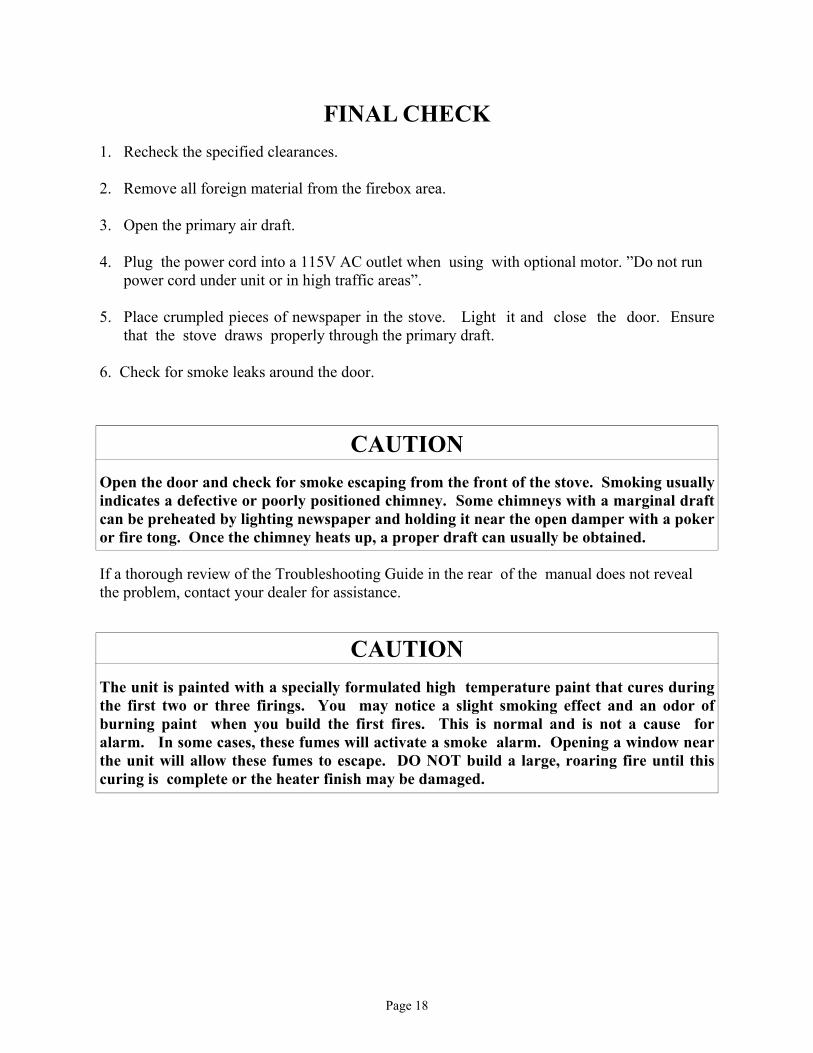
FINAL CHECK 1. Recheck the specified clearances. 2. Remove all foreign material from the firebox area. 3. Open the primary air draft. 4. Plug the power cord into a 115V AC outlet if optional motor is being used. “Do not run power cord under unit or in high traffic areas. 5. Place rumpled pieces of newspaper in the stove. Light it and close the door. Ensure that the
stove draws properly through the primary draft. NOTE: “Do not use grate or elevate fire. Build wood fire directly on hearth.” 6. Check for smoke leaks around the door. 7. Open the door and check for smoke escaping from the front of the stove. Smoking usually indicates
a defective or poorly positioned chimney. Some chimneys with a marginal draft can be pre-heated by lighting newspaper and holding it near the open damper with a poker or fire tong. Once the chimney heats up, a proper draft can usually be obtained.
If a thorough review of the Troubleshooting Guide in the rear of the manual does not reveal the problem, contact your dealer for assistance.
FIGURE 4

CAUTION
THE UNIT IS PAINTED WITH A SPECIALLY FORMULATED HIGH TEMPERATURE PAINT THAT CURES DURING THE FIRST TWO OR THREE FIRINGS. YOU MAY NOTICE A SLIGHT SMOKING EFFECT AND AN ODOR OF BURNING PAINT WHEN YOU BUILD THE FIRST FIRES. THIS IS NORMAL AND IS NOT A CAUSE FOR ALARM. IN SOME CASES, THESE FUMES WILL ACTIVATE A SMOKE ALARM. OPENING A WINDOW NEAR THE UNIT WILL ALLOW THESE FUMES TO ESCAPE. DO NOT BUILD A LARGE, ROARING FIRE UNTIL THIS CURING IS COMPLETE OR THE HEATER FINISH MAY BE DAMAGED. The connector and/or chimney should be inspected at least once a month during the heating season to determine if a creosote buildup has occurred.
CAUTION
NEVER USE GASOLINE, GASOLINE-TYPE LANTERN FUEL, KEROSENE, CHARCOAL LIGHTER FLUID OR SIMILAR LIQUIDS TO START OR "FRESHEN UP" A FIRE IN THE HEATER. KEEP ALL SUCH LIQUIDS WELL AWAY FROM THE STOVE WHEN IT IS IN USE. ALL FLUIDS OF THIS TYPE GIVE OFF VOLATILE FUMES AND CAN AND WILL EXPLODE!! DON'T TAKE A CHANCE WITH THE SAFETY OF YOUR HOME AND FAMILY.
Page 9

SECTION III PRE-FAB INSERT INSTALLATION
The Model 74 has been tested with the following UL listed manufactured Pre-Fab Fireplaces: Heatilator Security Tempco Preway Marco FMI Woodside Majestic The Model 74 will fit any of the models that are large enough to accept them. NOTE: A full chimney liner is required in a Zero Clearance or pre-fab fireplace. NOTE: The ash lip, smoke baffle, and smoke shelf may be removed if necessary to provide room for these models. Any other alteration to the unit will void ALL NBC manufacturer's responsibility and liability. The warning label below must be attached to the back of the fire -place. Except for the “NOTES” above, please follow the instructions for Masonry Insert Installation including Minimum Clearances for stove and floor protector in Section II.
WARNING: This fireplace must be restored to its original condition for safe use, if the fireplace insert is removed.
Page 10

SECTION IV RESIDENTIAL FREESTANDING
INSTALLATION Select an installation location that will give the best airflow from the front of the
heater to the remainder of the home.
PREPARING THE STOVE FOR INSTALLATION
1. Inspect the unit for any obvious physical damage.
2. Plug the power cord into a 115V AC outlet to test the motor and fan when optional motor is being used. “Do not run power cord under unit or in high traffic areas”.
3. Check the primary air draft control to ensure that it slides freely.
4. Remove any items from within the firebox. Spread a dropcloth on the floor behind the heater. Next, tilt the heater so that the back is on the drop cloth.
5. If leg kit is to be used follow steps 1-4.
6. Then obtain four legs, attach the legs to holes in bottom of unit with bolts and washers supplied with the leg kit. (See Figure 4.)
7. If pedestal kit is being used,(and out side air is required See Page 25) open the corresponding freestanding kit and obtain the stand. Place the stand against the bottom of
the heater (angle side to heater).Center stand front to rear ,and also center the stand left and right ,and mark screw locations on bottom of the stove through outer holes of stand mounting angles. Set stand aside and drill four 7/32" holes in heater bottom.Then mount stand to bottom of heater with screws provided. (See Figure 4A.)
8. Obtain four (4) 3/16" self-tapping screws and secure the stand to the heater.
9. Reposition the heater to the upright position. Figure 4 Figure 4A
FOUR NEW HOLES
Page 11

Chimney This model is designed for connection to any listed 2100º UL103 HT chimneys and parts. Follow chimneys manufacturer's instructions carefully. This room heater must be converted to (1) a chimney complying with the requirements for Type HT chimneys in the Standard for chimneys, Factory-Built, Residential, Type and Building Heating Appliance, UL 103, or (2) a code approved masonry chimney with a flue liner.
Floor Protection: Floor protection must be 3/8” minimum thickness non-combustible material or equivalent. How to use alternate materials and how to calculate equivalent thickness. An easy means of determining if a proposed alternate floor protector meets requirements listed in the appliance manual is to follow this procedure: 1. Convert specification to R-value: R-value is given—no conversion is needed. K– factor is given with a required thickness (T) in inches: C-factor is given: R=1/C 2. Determine the R-value of the proposed alternate floor protector. Use the formula in step (1) to convert values not expressed as “R” For multiple layers, add R-values of each layer to determine the overall R-value. 3. If the overall R-value of the system is grater than the R-value of the specified floor
protector, the alternate is acceptable. Example: The specified floor protector should be 3/4” thick material with a K-factor of 0.84. The proposed alternate is 4” brick with a C-factor of 1.25 over 1/8” mineral board with a K-factor of 0.29. Step (a): Use formula above to convert specification to R-value. R= 1/K x T = 1/0.84 x .75 = 0.893
Page 12

Step (b): Calculate R of proposed system. 4” brick of C=1.25, therefore Rbrick = 1/C = 1/1.25 =0.80 1/8” mineral board of K = 0.29, therefore Rmin.bd. =1/029 x0.125 = 0.431 Step (c): Compare proposed system R of 1.231 to specified R of 0.893. Since proposed system R is greater than required , the system is acceptable. Definitions: Thermal conductance = C = Btu = W (hr)(ft²)(°F) (m²)(°K) Thermal conductance = K = (Btu)(inch) = W = (Btu) (hr)(ft²)(°f) (m)(°K) (hr)(tf)(°F) Thermal conductance = R = (ft²)(hr)(°F) = (m²)(°K) Btu W Install in accordance with 24 CFR, Part 3280 (HUD).
CAUTION
SPECIAL METHODS ARE REQUIRED WHEN PASSING THROUGH A WALL OR CEILING. SEE INSTRUCTIONS AND BUILDING CODES. “DO NOT CONNECT THIS UNIT TO A CHIMNEY FLUE SERVING ANOTHER APPLIANCE.” DETERMINING THE CHIMNEY LOCATION A. CEILING EXIT (USING SINGLE WALL (minimum 24ga.) pipe and 2100° UL 103 HT type chimney system listed with manufacturer in this section of manual.) (See Page 12.)
1. Suspend a plumb bob from the ceiling above the unit so that the weight is hanging in the center of the flue exit. (A small weight on a string will serve as a plumb bob.) Mark the ceiling where the string is suspended to locate the center of the chimney.
2. After locating the center of the hole, install the ceiling support box, chimney flashing
and rain cap per the chimney manufacturer’s instructions.
Now connect the stove and ceiling support box using #24 ga. minimum blue or black steel connector pipe (DO NOT USE GALVANIZED PIPE). Connect each section so the crimped end faces downward, and secure each section to each other using at least three (3) sheet metal screws or rivets. Also use three (3) sheet metal screws to fasten pipe to collar on heater. (See Figure 5. Page 14.)
Page 13

B. Wall Exit Into Metal Tee-Box 1. Mark the plumb line on the wall directly behind the center of the heater. (See Figure 6.) NOTE: When using 24# ga. minimum blue or black steel pipe, maintain 18" between pipe and ceiling. NOTE: Floor protector must be under horizontal pipe exit (See Figure 9. Page 19. ) 2. Place the vertical portion of the heater pipe and the elbow in position and project a
point onto the plumb line level with the center of the elbow.
Figure 6
ATTIC
CEILING
"TEE" BOX ASSEM.CENTER LINEOF ELBOW
MARK PLUMB LINEWALL
WALL PASS-THROUGH CONNECTOR
18" MIN.
TEE BOX ASSEM. CLEAN OUT ACCESS
FLOOR PROTECTOR
3 SHEET METAL SCREWS OR RIVETS
CEILING
ROOF
Figure 5
COLLAR
3 SHEET METAL SCREWS
Figure 5
COLLAR
3 SHEET METAL SCREWS
Page 14

3. Measure up so there will be at least 1/4" rise per foot of horizontal connector pipe,
maintaining clearances to the ceiling as noted in (Figure 6 Page 14.) This will give you the center of the hole for the chimney penetration.
4. After locating the center of the penetration, install the tee-box and chimney as per the
chimney manufacturer's specifications. 5. Connect the chimney connector to the tee-box using #24 ga. minimum blue or black steel
connector pipe. DO NOT use galvanized pipe. Connect each section so the crimped end faces downward, and secure each section to each other using three (3) sheet metal screws or rivets. (See Figure 7.)
C. Wall Exit Into Masonry Flue (Using Single Wall Pipe.) 1. Before connecting these units to a masonry chimney, determine that the masonry flue pass
-through connector thimble meets the NFPA-211 Code and local building codes and is a minimum of 18" from the ceiling. If the connector thimble does not meet these codes, the pass-through connector must be modified.
Figure 7
CEILING CENTER LINE OF ELBOW SECURE WITH (3) SHEET METAL SCREWS
1/4” RISE PER FT’
MASONRY CHIMNEY
FLOOR PROTECTOR See Figure 9. Page 19.
CLEAN OUT DOOR
MASONRY FLUE LINERS
MARK PLUM LINE SEAL AROUND PIPE TO THIMBLE OR PASS-THROUGH CONNECTOR WITH NON-COMBUSTIBLE MATERIAL WALL
Page 15

Connectors may pass through walls or partitions constructed of combustible material if the connector is:
(a) Either listed for wall pass-through or is routed through a device listed for wall pass-through and is installed in accordance with the conditions of the listing.
(b) Selected or fabricated in accordance with the conditions and clearances as stated in the NFPA-211 Code. Any unexposed metal that is used as part of a wall pass-through system and is exposed to flue gases shall be constructed of stainless steel or other equivalent material that will resist corrosion, softening, or cracking from flue gases at temperatures up to 1800o F.
In addition, a connector to a masonry chimney shall extend through the wall to the inner face or liner but not beyond, and shall be firmly cemented to masonry.
EXCEPTION: A thimble may be used to facilitate removal of the chimney connector for cleaning, in which case the thimble shall be permanently cemented in place with high-temperature cement. 2. Once the through-the-wall thimble codes are met, simply connect the chimney collar to
the wall pass-through connector using #24 ga. minimum, blue or black steel connector pipe as follows: (a) Maintain 1/4" rise per foot (horizontal length) from the appliance to the chimney.
(b) Connect each section so the crimped end faces downward.
(c) Secure each section to each other using at least three (3) sheet metal screws or rivets.
(d) Use three (3) sheet metal screws to fasten pipe to connector collar on heater.
D. Ceiling Exit-Close Clearance 1. Suspend a plumb bob from the ceiling above the unit so that the weight is hanging in the
center of the flue exit (A small weight on a string will serve as a plumb bob). Mark the ceiling where the string is suspended to locate the center of the chimney hole.
2. After locating the center of the hole, install the ceiling support box, chimney flashing
and rain cap. 3. Install Double Wall Connector and close clearance chimney systems per manufacturer’s
written instructions. See stove manufacturer's list of tested pipes in this manual. (See Page 17.)
Page 16

Figure 8
This unit may be installed using the following double wall close clearance chimney systems: (1) 6" Simpson Dura-Vent double wall chimney connector “Type DVL” and 6" Simpson Dura-Vent 2100º HT. “Type DP” chimney. (2) 6" Security Type DL double wall connector and 6" Security Type "ASHT" High Temp Chimney. (3)6" Selkirk Metal Bestos Model “DS” double wall connector- 6" Selkirk Metal Bestos Model SSII Type HT Chimney System. (4) 6" Metal Fab Type “DW” double wall connector– 6" Metal Fab 2100 HT chimney. (5) 6" Air Jet. (6) Jakes Evans. For minimum clearances (see pages 19,20,21.) Alcove Installation Clearances
Alcove installation must use 6" Double Wall Connector and 6" Type 2100° UL 103 HT Pipe listed for close clearance reduction that is listed in this manual. For measurements and minimum clearances (See Page 23.)
CEILING
ROOF
CHIMNEY CONNECTOR
CEILING
ROOF
COLLAR
Page 17
FINAL CHECK 1. Recheck the specified clearances. 2. Remove all foreign material from the firebox area. 3. Open the primary air draft. 4. Plug the power cord into a 115V AC outlet when using with optional motor. ”Do not run power cord under unit or in high traffic areas”. 5. Place crumpled pieces of newspaper in the stove. Light it and close the door. Ensure
that the stove draws properly through the primary draft. 6. Check for smoke leaks around the door.
CAUTION Open the door and check for smoke escaping from the front of the stove. Smoking usually indicates a defective or poorly positioned chimney. Some chimneys with a marginal draft can be preheated by lighting newspaper and holding it near the open damper with a poker or fire tong. Once the chimney heats up, a proper draft can usually be obtained. If a thorough review of the Troubleshooting Guide in the rear of the manual does not reveal the problem, contact your dealer for assistance.
CAUTION The unit is painted with a specially formulated high temperature paint that cures during the first two or three firings. You may notice a slight smoking effect and an odor of burning paint when you build the first fires. This is normal and is not a cause for alarm. In some cases, these fumes will activate a smoke alarm. Opening a window near the unit will allow these fumes to escape. DO NOT build a large, roaring fire until this curing is complete or the heater finish may be damaged.
Page 18

CLEARANCES FOR MODEL 74 MINIMUM CLEARANCES TO COMBUSTIBLES
RESIDENTIAL/ SINGLE WALL CONNECTOR WITHOUT OPTIONAL CLOSE CLEARANCE SHIELDS
AND PIPE SHIELD
Figure 9
MODEL A B C D E F G H MODEL 74 25" 8" 10.5" 8" 8" 6" 20" 10” NOTE: All clearances are to combustibles using single wall pipe without optional close clearance shields and pipe shield, minimum floor protector. The clearances above may be reduced. Follow NFPA-211 codes if available or follow instructions on next page.
BACK WALL
SID
E W
ALL
A
E
BF
C C
D
G D D C
G
B C F
A
E
H
Page 19
CLEARANCES FOR MODEL 74 MINIMUM CLEARANCES TO COMBUSTIBLES
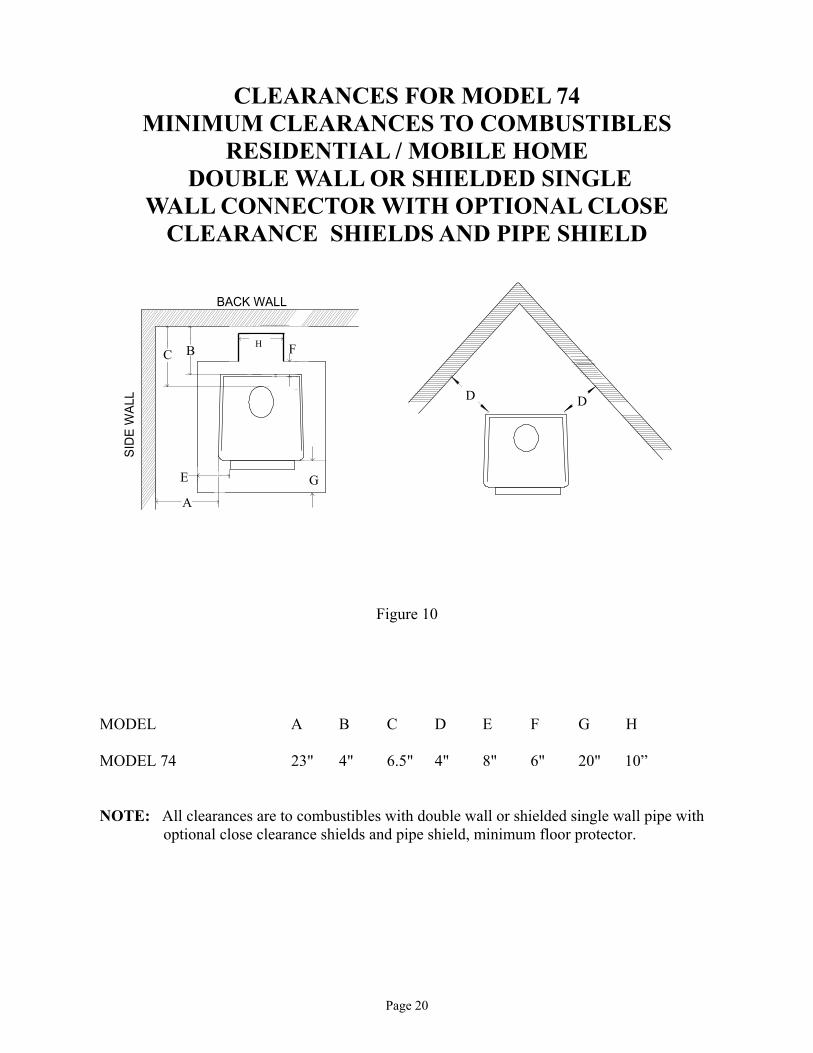
RESIDENTIAL / MOBILE HOME DOUBLE WALL OR SHIELDED SINGLE
WALL CONNECTOR WITH OPTIONAL CLOSE CLEARANCE SHIELDS AND PIPE SHIELD
Figure 10
MODEL A B C D E F G H MODEL 74 23" 4" 6.5" 4" 8" 6" 20" 10” NOTE: All clearances are to combustibles with double wall or shielded single wall pipe with optional close clearance shields and pipe shield, minimum floor protector.
C CD D
BACK WALL
SID
E W
ALL
A
E
BF
D
GC
G
B C H F
A
E
Page 20

CLEARANCES FOR MODEL 74 MINIMUM CLEARANCES TO COMBUSTIBLES
RESIDENTIAL / MOBILE HOME DOUBLE WALL OR SHIELDED SINGLE WALL
CONNECTOR WITHOUT OPTIONAL CLOSE CLEARANCE SHIELDS
Figure 10
MODEL A B C D E F G H MODEL 74 25" 4" 6.5" 4" 8" 6" 20" 10” NOTE: All clearances are to combustibles using double or shielded single wall pipe without close clearance shields and pipe shield, minimum floor protector.
C CD D
BACK WALL
SID
E W
ALL
A
E
BF
D
GC
G
B C H
A
E
F
Page 21

Installation of (Optional) Close Clearance Shields and Pipe Shield 1. Taking close clearance side shields, hold up to side of stove leaving 1/4" gap between shield
and top of stove.
2. Make reference mark in center of pre-punched hole in top & bottom of shield. Drill two (2) 3/32" holes in back of unit on each side. Insert self tapping screws in through shield into stove.(SEE PICTURE BELOW)
3. Drill two (2) 3/16" holes in the sides of the stove where the shield meets the front side. Insert two (2) 3/8" self-tapping screws. (SEE PICTURE BELOW)
4. Next loosen two (2) top screws holding side shield at rear top. Insert pipe shield where back shield and top rear side shield meets. Leave a 1” gap from the top of stove to the pipe shield, tighten screws.(SEE PICTURE BELOW)
Installation of (Optional) Close Clearance Shields
Installation of (Optional) Pipe Shield
1” TYP. 1/4” TYP.
13/16” TYP.
Pipe Shield
Close Clearance Shields Close Clearance Shields
Loosen these top shield screws
Page 22

CLEARANCES FOR MODEL 74 ALCOVE INSTALLATION DOUBLE WALL
OR SHIELDED SINGLE WALL CONNECTOR WITH OPTIONAL CLOSE CLEARANCE SHIELDS
AND PIPE SHIELD
Figure 11
MODEL A B C D E I J K MODEL 74 23" 4" 6.5" 84" 36" 8” 6” 20” NOTE: All clearances are to combustibles using double wall or shielded single wall pipe and optional close clearance shields and pie shield only, minimum floor protector.
D
BACK WALL
SID
E W
ALL
A
E
BF
D
GC
K
B C
I
A
E
H J
Page 23
SECTION V FREESTANDING MOBILE HOME
INSTALLATION
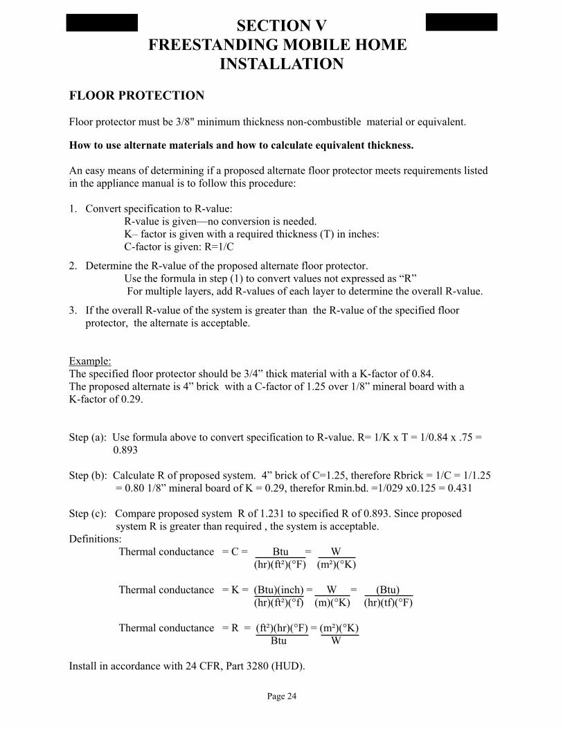
FLOOR PROTECTION Floor protector must be 3/8" minimum thickness non-combustible material or equivalent. How to use alternate materials and how to calculate equivalent thickness. An easy means of determining if a proposed alternate floor protector meets requirements listed in the appliance manual is to follow this procedure: 1. Convert specification to R-value: R-value is given—no conversion is needed. K– factor is given with a required thickness (T) in inches: C-factor is given: R=1/C
2. Determine the R-value of the proposed alternate floor protector. Use the formula in step (1) to convert values not expressed as “R” For multiple layers, add R-values of each layer to determine the overall R-value.
3. If the overall R-value of the system is greater than the R-value of the specified floor protector, the alternate is acceptable.
Example: The specified floor protector should be 3/4” thick material with a K-factor of 0.84. The proposed alternate is 4” brick with a C-factor of 1.25 over 1/8” mineral board with a K-factor of 0.29. Step (a): Use formula above to convert specification to R-value. R= 1/K x T = 1/0.84 x .75 = 0.893 Step (b): Calculate R of proposed system. 4” brick of C=1.25, therefore Rbrick = 1/C = 1/1.25 = 0.80 1/8” mineral board of K = 0.29, therefor Rmin.bd. =1/029 x0.125 = 0.431 Step (c): Compare proposed system R of 1.231 to specified R of 0.893. Since proposed system R is greater than required , the system is acceptable. Definitions: Thermal conductance = C = Btu = W (hr)(ft²)(°F) (m²)(°K) Thermal conductance = K = (Btu)(inch) = W = (Btu) (hr)(ft²)(°f) (m)(°K) (hr)(tf)(°F) Thermal conductance = R = (ft²)(hr)(°F) = (m²)(°K) Btu W Install in accordance with 24 CFR, Part 3280 (HUD).
Page 24

CHIMNEY This model is designed for connection to any 2100° UL 103 HT chimneys. Follow chimney manufactures instructions carefully.
TOOLS FOR INSTALLATION Drop cloth 3/32" Metal drill bit 5/16" Magnetic socket chuck adapter, 5/16" wrench (box or socket) or adjustable wrench Jigsaw with masonry, metal and wood blades
PREPARING THE HEATER FOR INSTALLATION
1. Inspect the unit for any obvious physical damage. 2. Plug the power cord into a 115V AC outlet to test the motor and fan when using with
optional motor. “Do not run power cord under unit or in high traffic areas”. 3. Check the primary air draft control to ensure it operates freely. 4. Remove any items from within the firebox. Spread a drop cloth on the floor behind the heater. Next, tilt the heater so that the back is on the drop cloth.
NOTE: If outside air is required ,or being used the following must be done. Locate optional air inlet plate opening on outer bottom of unit. With pliers or screwdriver, pry and twist out inner tab till it breaks loose. This is where your outside air enters unit after installation is complete. (See Figure 12.)
5. Open the proper outside air freestanding kit and obtain the stand. Place the stand against the bottom of heater (angle side to heater). Center the stand left and right and front to back and mark screw locations on bottom through outer holes of stand mounting angles. Set stand aside and drill four (4) 7/32" holes in heater bottom. 6. Obtain four (4) 3/16" self-tapping screws and secure the stand to the heater. (See Figure 12.) 7. Reposition the heater to the upright position.
Figure 12
OPTIONAL REMOVABLE AIR INLET PLATE
Page 25
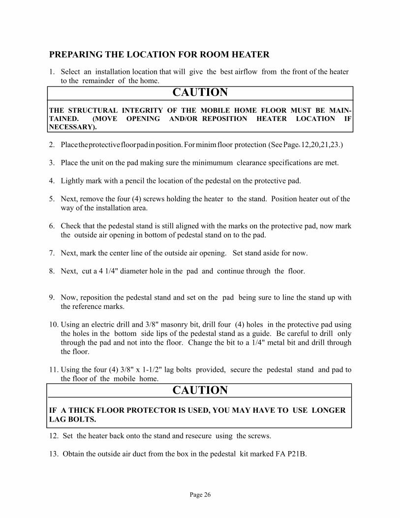
PREPARING THE LOCATION FOR ROOM HEATER 1. Select an installation location that will give the best airflow from the front of the heater
to the remainder of the home.
CAUTION THE STRUCTURAL INTEGRITY OF THE MOBILE HOME FLOOR MUST BE MAIN-TAINED. (MOVE OPENING AND/OR REPOSITION HEATER LOCATION IF NECESSARY). 2. Place the protective floor pad in position. For minim floor protection (See Pages 12,20,21,23.) 3. Place the unit on the pad making sure the minimumum clearance specifications are met. 4. Lightly mark with a pencil the location of the pedestal on the protective pad. 5. Next, remove the four (4) screws holding the heater to the stand. Position heater out of the
way of the installation area. 6. Check that the pedestal stand is still aligned with the marks on the protective pad, now mark
the outside air opening in bottom of pedestal stand on to the pad. 7. Next, mark the center line of the outside air opening. Set stand aside for now. 8. Next, cut a 4 1/4" diameter hole in the pad and continue through the floor. 9. Now, reposition the pedestal stand and set on the pad being sure to line the stand up with
the reference marks. 10. Using an electric drill and 3/8" masonry bit, drill four (4) holes in the protective pad using
the holes in the bottom side lips of the pedestal stand as a guide. Be careful to drill only through the pad and not into the floor. Change the bit to a 1/4" metal bit and drill through the floor.
11. Using the four (4) 3/8" x 1-1/2" lag bolts provided, secure the pedestal stand and pad to
the floor of the mobile home.
CAUTION IF A THICK FLOOR PROTECTOR IS USED, YOU MAY HAVE TO USE LONGER LAG BOLTS. 12. Set the heater back onto the stand and resecure using the screws. 13. Obtain the outside air duct from the box in the pedestal kit marked FA P21B.
Page 26

14. From under the mobile home, slip the duct up through the 4-1/4" hole. Push up until the
face of the outside air duct contacts the underside of the floor of the mobile home. For certain floor thickness, you may have to shorten the length of the outside air duct.
15. Secure the outside air duct to the floor using the four (4) #10x1 screws provided. (See Figure 12A.)
Figure 12A
Ceiling Exit (Using Close Clearance listed chimney) 1. Suspend a plumb bob from the ceiling above the unit so that the weight is hanging in the
center of the flue exit. ( A small weight on a string will serve as a plumb bob.) Mark the ceiling where the string is suspended to locate the center of the chimney hole.
24" min.(610 mm)
OUTSIDE AIR DUCT THROUGH FLOOR WHEN MOBLE HOME IS NOT UNDERPENNED
RAIN CAP
FLASHING
RADIATION SHIELD
24" min.(610 mm)
OUTSIDE AIR DUCT THROUGH UNDERPENNED
RAIN CAP
FLASHING
RADIATION SHIELD
36" TYP.36" TYP.
20 FT. MAX.
Page 27

2. After locating the center of the hole install the ceiling support box, chimney flashing and rain cap. Only use2100° UL 103 HT chimney and parts listed in this manual per the chimney manufactures instruction .
CAUTION REFER TO CHIMNEY MANUFACTURER’S INSTRUCTIONS FOR ASSEMBLY AND DISASSEMBLY OF CHIMNEY PARTS. BE SURE TO FOLLOW CHIMNEY INSTRUC-TIONS FOR PROPER CLEARANCES TO COMBUSTIBLE AND PROPER AIR SPACING REQUIRED. 3. Add additional pipe until both of the following are met:
(a) Chimney pipe is 3 feet higher than roof at the point where it penetrates the roof. (b) Chimney pipe height is at least 2 feet higher than any part of the roof within 10 feet of the chimney. (See Figure 12A. Page 27.) 4. Using only double wall chimney connector listed in this manual (See Page 17), connect the heater to the chimney by following chimney manufacturer's installation instructions exactly. (See Figure 13.)
Figure 13
3 SHEET METAL SCREWS OR RIVETS
CEILING
ROOF
COLLAR
3 SHEET METAL SCREWS
COLLAR
3 SHEET METAL SCREWS
Page 28
FINAL CHECK
1. Recheck the specified clearances. 2. Remove all foreign material from the firebox area. 3. Open the primary air draft. 4. Plug the power cord into a 115V AC outlet when using with optional motor. Do no run power cord under unit or in high traffic areas. 5. Place crumpled pieces of newspaper in the stove. Light it and close the door. Ensure that
the stove draws properly through the primary draft. 6. Check for smoke leaks around the door. 7. Open the door and check for smoke escaping from the front of the stove. Smoking usually
indicates a defective or poorly positioned chimney. Some chimneys with a marginal draft can be preheated by lighting newspaper and holding it near the open damper with a poker or fire tong. Once the chimney heats up, a proper draft can usually be obtained.
If a thorough review of the Troubleshooting Guide in the rear of the manual does not reveal the problem, contact your dealer for assistance.
CAUTION THE UNIT IS PAINTED WITH A SPECIALLY FORMULATED HIGH TEMPERATURE PAINT THAT CURES DURING THE FIRST TWO OR THREE FIRINGS. YOU MAY NOTICE A SLIGHT SMOKING EFFECT AND AN ODOR OF BURNING PAINT WHEN YOU BUILD THE FIRST FIRES. THIS IS NORMAL AND IS NOT A CAUSE FOR ALARM. IN SOME CASES, THESE FUMES WILL ACTIVATE A SMOKE ALARM. OPENING A WINDOW NEAR THE UNIT WILL ALLOW THESE FUMES TO ESCAPE. DO NOT BUILD A LARGE ROARING FIRE UNTIL THIS CURING PROCESS IS COMPLETE OR THE HEATER FINISH MAY BE DAMAGED.
Page 29

SECTION VI WOOD HEATER SAFETY
Certain safety hazards are inherent in any wood heater installation. You should be aware of these so that a safe and proper installation can be made. 1. FAULTY CHIMNEY: An older masonry chimney should be thoroughly checked to be sure
there are no holes or weak spots which could allow sparks or hot gases to escape. 2. HEAT CONDUCTION: Placing combustible materials too close to a heater or chimney can
be a fire hazard. By keeping these particular hazards in mind as you install and use your room heater you can ensure a safe, reliable installation. The chimney and chimney connector should be inspected once every two months. Any build-up of soot should be removed to prevent the risk of a chimney fire. To remove chimney or chimney connector: Remove screws or fasteners. Remove pipe and clean with steel brush. Replace chimney or chimney connector, and replace screws and/or fasteners.
CAUTION NEVER USE GASOLINE, GASOLINE TYPE LANTERN FUEL, KEROSENE, CHARCOAL LIGHTER FLUID OR SIMILAR LIQUIDS TO START OR "FRESHEN UP" A FIRE IN THE HEATER. KEEP ALL SUCH LIQUIDS WELL AWAY FROM THE STOVE WHEN IT IS IN USE. ALL FLUIDS OF THIS TYPE GIVE OFF VOLATILE FUMES AND CAN AND WILL EXPLODE!! DON'T TAKE A CHANCE WITH THE SAFETY OF YOUR HOME AND FAMILY. CAUTION: Never remove ashes from heater with blower running. DISPOSAL OF ASHES: Ashes should be placed in a metal container with a tight fitting lid. The closed container of ashes should be placed on a non-combustible floor or on the ground, well away from all combustible materials pending final disposal. If the ashes are disposed of by burial in soil or otherwise locally dispersed, they should be retained in the closed container until all cinders have thoroughly cooled. CREOSOTE-FORMATION AND NEED FOR REMOVAL: When wood is burned slowly, it produces tar and other organic vapors, which combine with expelled moisture to form creosote. The creosote vapors condense in the relatively cool chimney flue of a slow-burning fire. As a result, creosote residue accumulates on the flue lining. When ignited this creosote makes an extremely hot fire.
Page 30

SECTION VII OPERATION This section of the manual is to help you get the maximum efficiency and maximum smoke (particulate) reduction from your heater. If you should experience any difficulty or have any questions concerning your heater, contact your dealer for assistance. NOTE: The manufacturer recommends that for maximum performance burn natural seasoned hard wood.
Build a fire for maximum efficiency. This model burns wood and extracts heat so efficiently, a large fire is not necessary. A large fire not only wastes energy, it usually results in the home being too warm for comfort.
The following steps will serve as a guide for operating your stove.
BUILDING A FIRE
1. Open the door.
2. Open the primary air control under hearth, push in. To close pull all the way out.
3. Twist two pieces of non-colored newspaper into a roll and place them on the floor of the firebox.
NOTE: “Do not use grate or elevate fire. Build wood fire directly on hearth.”
4. This model is not designed for the use of grates, andirons or other methods of supporting the fuel.
5. Lay several pieces of dry kindling on top of the newspaper.
6. Place three or four small pieces of firewood, 2"-3" in diameter, on top of the kindling.
7. Light the newspaper in the front. Close and latch the door. Don't leave the fire unattended at this point. The draft system of the heater should start quickly. It may be necessary to preheat the chimney to get the draft started. To do this, open the door and add newspaper to the top rear of the wood. Light or let this paper ignite and allow to burn while holding the door slightly cracked. Once the draft has started, close and lock the door. You are over- heating the unit if the chimney and or connector glows red.
8. NOTE: After embers and a coal bed have been established, load the heater with seasoned natural hard wood, placing it length way front to rear.
NOTE: THE FUELING DOOR MUST REMAIN CLOSED DURING OPERATION.
BURN RATE LOW MED-LOW MED-HI HI AIR SETTINGS 5/16” 3/8” 5/8” WIDE OPEN
NOTE: If the optional blower is being used on the Model 74. Your stove is equipped with a automatic thermostat. When the stove gets hot enough, the thermostat will activate the room air blower. Set fan speed according to desired heat output.
NOTE: When refueling or removing ashes turn “OFF” room air blower. Be sure to turn room air blower back on when finished.
NOTE: Do not run power cord underneath heater, or in walk way or heavy traffic areas.
Page 31

SECTION VIII TROUBLESHOOTING
PROBLEM POSSIBLE CAUSE SOLUTION
1. Sluggish Heater 1. Obstruction in Chimney 2. Improperly sealed trim
kit or direct connect kit 3. Manual damper in
chimney is closed 4. Wet or unseasoned wood
being burned 5. Poor chimney draft 6. Improper wood loading
1. Check for and remove obstruction
2. (a) Check trim kit gasketing seal to fireplace and gasket as necessary to seal unit. Gasket under front bottom of stove if needed. (b) Check seal if using direct connect and correct.
3. Open manual damper and wire shut with stainless steel wire or remove damper
4. Burn dry natural seasoned hard wood
5. Improper chimney height or wrong size flue is being used. Cooler temperatures caused by external chimney.
6. Load wood length way from front to rear
Page 32

2. High fuel consumption 3. Backpuffing 4. Smoke rollout when heater
door is opened
1. (a) Close inlet air control as much as possible to maintain desired heat output. (b) Check gaskets, reinstall fiberglass gasketing around doors and glass as necessary
2. Check door gasket, check adjustment of door latch
1. (a) Smoke shelf in
chimney is filled with creosote & ash (b) Chimney may need wind diverter. Raise chimney for better draft.
1. (a) Smoke shelf in
chimney is filled with creosote & ash (b) Chimney may need wind diverter. Raise chimney for better draft.
2. Crack door for 15
seconds before fully opening door.
1. Improper regulation of draft or inlet air
2. Improper door fitting 1. Gusts of Wind 1. Wind gusts blowing down
the chimney 2. Opening heater door too
fast
PROBLEM POSSIBLE CAUSE SOLUTION
Page 33

NEW BUCK CORPORATION (NBC) "LIMITED WARRANTY" FOR THE BUCK STOVE
PLEASE READ THIS WARRANTY CAREFULLY
PRODUCTS COVERED This warranty covers the New Buck Stove heating unit, as long as it is owned by the original purchaser, including optional and standard accessories purchased at the same time, subject to terms, limitations, and conditions herein set out. PRODUCTS NOT COVERED This warranty does not cover the following: Glass; Refractory material such as refractory cement or firebrick; Gaskets. This Warranty will also not cover any damage and/or failure caused by abuse or improper installation of the products covered. WARRANTY TIME PERIODS (A) Period I For one year from the date of purchase, NBC will replace or repair, at its option, any part defective in materials or workmanship. The costs of parts only are included. The customer pays any labor or transportation charges required. Thereafter B) Period II For the period after the first year from the date of purchase and extending for 5 years as long as the Buck Stove is owned by the original purchaser, NBC will repair or replace, at its option, any part defective in materials or workmanship, with the exception of: electrical motors, wiring, switches, and components: optional and standard accessories; and all parts not permanently attached to the heating unit. Parts not permanently attached to the heating unit are defined as those items designed to be removed from the stove, including those removable with common hand tools. The costs of parts only are included. The customer pays any labor or transportation charges required. . PROCEDURE Should you feel that your BUCK STOVE is defective, you should contact any Buck Stove dealer for the name of your nearest authorized Buck Stove service representative, who will instruct you on the proper procedure, depending on which Warranty Time Period (Period I or Period II) applies.
Page 34

If for any reason you are dissatisfied with the suggested procedures, you may contact us in writing at: New Buck Corporation Customer Service Department P. O. Box 69 Spruce Pine, NC 28777 CONDITIONS AND EXCLUSIONS A. Replacement of parts may be in the form of new or fully reconditioned parts, at NBC's
option. B There is no other express warranty. All implied warranties of Merchantability and
Fitness for Use are limited to the duration of the Express Warranty. C. New Buck Corporation is not liable for indirect, incidental, or consequential damages in
connection with the use of the product including any cost or expense of providing substitute equipment or service during periods of malfunction or non-use.
Some states do not allow the exclusion of incidental or consequential damages, so the above exclusion may not apply to you. D. All warranty repairs under this warranty must be performed by an
authorized Buck Stove service representative. Repairs or attempted repairs by anyone other than an authorized service representative are not covered under this warranty. In addition, these unauthorized repairs may result in additional malfunctions, the correction of which is not covered by warranty.
OTHER RIGHTS This warranty gives you specific legal rights, and you may also have other rights, which vary from state to state. OWNER REGISTRATION CARD The attached Owner Registration Card must be completed in entirety and mailed within 30 days from the date of purchase or from the date of installation, if installed by a factory certified installer, to New Buck Corporation in order for warranty coverage to begin. PLEASE NOTE: The Owner Registration Card must contain the Authorized Buck Stove Dealer Code Number and the Certified Installer's number (if applicable) for warranty coverage to begin. To be completed by selling distributor or dealer for customer: Warranty Card Not Available On Replacement Or Online Manuals

The following manual is the 51ZC cabinet manual…

MODEL 51ZC ZERO CLEARANCE CABINET
FOR USE WITH FIREPLACE MODELS 51, T-51, 74, T-74 ONLY. MAY BE INSTALLED IN RESIDENTIAL AND MOBILE HOME.
Contact your insurance company for coverage and installation inspection.
WARNING Do not attempt to build a fire in this product. It has been designed and safety tested for use only with Models 51,T-51,74,T-74 manufactured by NEW BUCK CORPORATION. Read
and follow the installation and operating instructions for this model. FEATURES PREPARATIONS INSTALLATION OPERATION MAINTENANCE SAFETY
SAFETY NOTICE
IF THIS HEATER IS NOT PROPERLY INSTALLED, A HOUSE FIRE MAY RESULT. FOR YOUR SAFETY, FOLLOW THE INSTALLATION INSTRUCTIONS. CONTACT THE AUTHORITY HAVE JURISDICTION ( SUCH AS MUNICIPAL BUILDING DEPARTMENT, FIRE DEPARTMENT, FIRE PREVENTION BUREAU, ect.) SHOULD BE CONSULTED BEFORE INSTALLATION TO DETERMINE THE NEED TO OBTAIN A PERMIT. KEEP THESE INSTRUCTIONS FOR FUTURE USE.
TESTED AND LISTED BY: ITS/WARNOCK HERSEY, MIDDLETON, WI
MANUFACTURED BY NEW BUCK CORPORATION - SPRUCE PINE, NC 28777
Revised February 15, 2010
BUCK STOVE

Page 1
TABLE OF CONTENTS
SECTION I: Residential Installation………………………………………………………..2 Chimney Location ………………………………………………………………………….4 Floor Protection .…………………………………………………………………………….6 Framing Construction Installation……………………………………………………….….7 Corner Location Framing …………………………………………………………………...10 SECTION II: Mobile Home Installation ………………………………………………….13 Framing Construction Installation ………………………………………………………...14 Alternate Floor Protector . ………………………………………………………………….17 Safety Precaution ..………………………………………………………………………….18 Preventive Maintenance ….. …………………………………………………………………..19 Chimney Cleaning. …………………………………………………………………………19 Heater Removal from Cabinet……. ………………...……………………………………...20 Reinstalling Heater into Cabinet . …………………………………………………………..21 Cabinet Identification .. ……………………………………………………………………..22 Warranty ….………………………………………………………………………………… ..23

Page 2
RESIDENTIAL INSTALLATION Listed NEW BUCK CORPORATION: Model 51ZC Zero Clearance Cabinet Assembly For Use With Models 51, T-51, 74, and T-74 Only.
CAUTION: Read through all of these instructions carefully. Follow approved Chimney Manufac-turer’s Installation exactly. Failure to install the Cabinet Fireplace, Stove and Chimney as described in the instructions will void the manufacturer’s warranty and may have an effect on your Homeowner’s Insurance. A major cause of chimney related fires is failure to maintain required clearances (air spaces) to combustible materials. It is of the utmost importance that these parts be installed only in accordance with these instructions.
“DO NOT USE CHEMICALS OR FLUIDS TO START THE FIRE.”
“DO NOT BURN GARBAGE OR FLAMMABLE FLUIDS.”
“DO NOT BUILD A FIRE DIRECTLY INSIDE THE ZC CABINET. IT IS DESIGNED SOLELY FOR HOUSING THE MODELS 51, T-51, 74, T-74 STOVES.” “WARNING -THIS FIREPLACE HAS NOT BEEN TESTED WITH AN UNVENTED GAS LOG SET. TO REDUCE THE RISK OF FIRE OR INJURY, DO NOT INSTALL AN UNVENTED GAS LOG SET INTO THIS FIREPLACE.”
CAUTION: “Never use gasoline, gasoline - type lantern fuel , kerosene, charcoal lighter fluid, or similar liquids to start or ‘freshen up’ a fire in this fireplace. Keep all such liquids well away from the fireplace while it is in use,” “Disposal of Ashes:
Ashes should be placed in a metal container with a tight-fitting lid. The closed container of ashes should be placed on a noncombustible floor or on the ground, well away from all combus-tible materials, pending final disposal. If the ashes are disposed of by burial in soil or otherwise locally dispersed, they should be retained in the closed container until all cinders have thor-oughly cooled.”
“Do Not Use Grate or Elevate Fire-Build Wood Fire Directly on Hearth in Stove.”
For operation and use of air, and damper controls, see stoves Owners Manual for use of air, and damper control. For operation and use of electrical assemblies, see stoves Owners Manual for use of electrical assemblies
“USE SOLID WOOD FUEL ONLY.”.
The Zero-Clearance Cabinet and the Models 51, T-51, 74, and T-74 Installed (hereafter referred to as the 51ZC) is designed for installation in a family dwelling, where minimum clearance is desired.
SECTION I

Page 3
INSTALLATION PRECAUTIONS The following precautions are mandatory for a safe installation. (A) Compliance with local building codes and regulations is mandatory. (B) Be careful not to damage the unit in handling and unpacking component parts and accessories. (C) Model 51zc Cabinet, use only 6"listed 2100º UL 103 HT TYPE Chimney with the 51zc Cabinet (ONLY AFTER) one of the follwing new Buck Corparation Stoves 51, T-51, 74, T-74, has been installed into the 51ZC Cabinet. (D) he chimney must extend a minimum of three feet (3') above the highest point where it penetrates the
roof (three feet (3') above a flat roof or up to a 2 /12 pitch roof ), and the chimney must extend a minimum of two feet (2') higher than any portion of the building within ten feet (10') of the chim-ney. The minimum height is fourteen feet (14'). The maximum height is thirty feet (30'). A two-inch (2") clearance must be maintained between the chimney and any combustible materials at all points.
(E) A rain cap must be used to terminate the chimney to prevent down-draft. Use the factory approved
rain cap which is approved for the type chimney being installed. (F) “DO NOT CONNECT THIS UNIT TO A CHIMNEY FLUE SERVING ANOTHER APPLIANCE.” DO NOT USE A FLUE INTENDED FOR A GAS APPLIANCE.”DO NOT CONNECT TO ANY DISTRIBUTION DUCT OR SYSTEM.”
Page 4
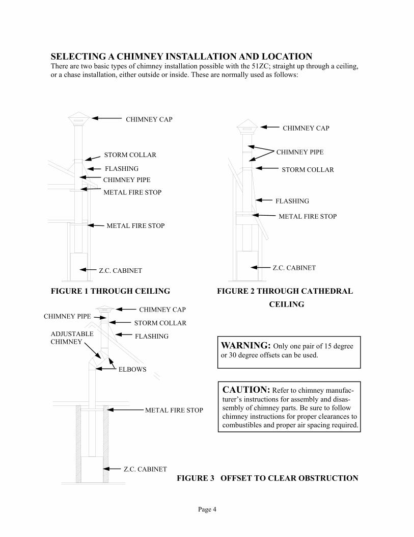
SELECTING A CHIMNEY INSTALLATION AND LOCATION There are two basic types of chimney installation possible with the 51ZC; straight up through a ceiling, or a chase installation, either outside or inside. These are normally used as follows:
CHIMNEY CAP
CHIMNEY CAP
CHIMNEY CAP
STORM COLLAR
STORM COLLAR
STORM COLLAR FLASHING
FLASHING
FLASHING
CHIMNEY PIPE
METAL FIRE STOP
METAL FIRE STOP
Z.C. CABINET
CHIMNEY PIPE
METAL FIRE STOP
Z.C. CABINET
ADJUSTABLE CHIMNEY
ELBOWS
METAL FIRE STOP
Z.C. CABINET
CHIMNEY PIPE
FIGURE 1 THROUGH CEILING FIGURE 2 THROUGH CATHEDRAL
CEILING
FIGURE 3 OFFSET TO CLEAR OBSTRUCTION
CAUTION: Refer to chimney manufac-turer’s instructions for assembly and disas-sembly of chimney parts. Be sure to follow chimney instructions for proper clearances to combustibles and proper air spacing required.
WARNING: Only one pair of 15 degree or 30 degree offsets can be used.

Page 5
B. Exterior Chase Installation: (See Figure 4). A chase is an enclosure built specifically to house a chimney. The interior of a chase is open from Model 51ZC to the roof, eliminating the need to cut through ceilings and the roof. Normally, a chase is built through the wall, and the Model 51ZC is located in the bottom of the chase, with the front of the unit flush with the interior wall. Chases are commonly veneered on the outside with brick, stone or wood to give the appearance of a conventional fireplace flue. Occasionally, they are built inside and boxed in, similar to a stairwell. When making a chase instal-lation, it is important to read the chimney manufacturer’s instructions prior to building, as there are spe-cific requirements for bracing a free standing flue that must be planned for. There are also occasions where offsets are used within a chase to accommodate unusual building designs, or to locate the Model 51ZC further into a room.
A. Straight up through ceiling (See Page 4 Figures 1 and 2). This is a simple installation normally used when installing a Model 51ZC inside an existing room, and in some cases, in new construction.
Refer to (Page 4 Figure 3) if an offset to clear an obstruction is needed.
WARNING: Only one pair of 15 degree or 30 degree offsets can be used.
FIGURE 4 EXTERIOR WALL CHASE
Z.C. CABINET
CHIMNEY CAP
STORM COLLAR
FLASHING
CHIMNEY PIPE
OPTIONAL METAL FIRESTOP RADIATION SHIELD
WALL BAND

Page 6
Floor Protection: or Hearth Protector Floor protection must be 3/8” minimum thickness non-combustible material or equivalent. How to use alternate materials and how to calculate equivalent thickness. An easy means of determining if a proposed alternate floor protector meets requirements listed in the appliance manual is to follow this procedure: 1. Convert specification to R-value: R-value is given—no conversion is needed. K– factor is given with a required thickness (T) in inches: C-factor is given: R=1/C 2. Determine the R-value of the proposed alternate floor protector. Use the formula in step (1) to convert values not expressed as “R” For multiple layers, add R-values of each layer to determine the overall R-value. 3. If the overall R-value of the system is grater than the R-value of the specified floor
protector, the alternate is acceptable. Example: The specified floor protector should be 3/4” thick material with a K-factor of 0.84. The proposed alternate is 4” brick with a C-factor of 1.25 over 1/8” mineral board with a K-factor of 0.29. Step (a): Use formula above to convert specification to R-value. R= 1/K x T = 1/0.84 x .75 = 0.893 Step (b): Calculate R of proposed system. 4” brick of C=1.25, therefore Rbrick = 1/C = 1/1.25 =0.80 1/8” mineral board of K = 0.29, therefore Rmin.bd. =1/029 x0.125 = 0.431 Step (c): Compare proposed system R of 1.231 to specified R of 0.893. Since proposed system R is greater than required , the system is acceptable. Definitions: Thermal conductance = C = Btu = W (hr)(ft²)(°F) (m²)(°K) Thermal conductance = K = (Btu)(inch) = W = (Btu) (hr)(ft²)(°f) (m)(°K) (hr)(tf)(°F) Thermal conductance = R = (ft²)(hr)(°F) = (m²)(°K) Btu W Install in accordance with 24 CFR, Part 3280 (HUD).

Page 7
FRAMING CONSTRUCTION AND INSTALLATION Except as noted, the 51ZC can be installed almost anywhere you desire. There are, however, a few clearance and framing restrictions that must be followed. (See Page 10 Figure 9), and (Page 11 Figure10) to make sure that these clearance restrictions are met. It is much wiser to place your Model 51ZC correctly at the start. You must ensure that the floor is of adequate strength to accept the load of this unit. If inadequate, the floor will require additional support, such as bracing. NOTE: A wooden base constructed of plywood or 2" x 4" boards is required in order to get proper clearance above the extended hearth (millboard, rock stone, etc.). Good planning is essential for a satisfactory installation, therefore, at this point you should have decided where the 51ZC is to be located and the route the chimney will follow to the roof-straight up, or chase. If you cannot decide the best route, contact your Dealer for assistance with the planning.
26" 26"
26"
CORNER
LOCATIO
N
ADJACENT ROOM OF EXTERIOR CHASE
INTERIOR LOCATION
FIGURE 5
Above (Figure 5) are framing location examples with depth dimensions for some typical configurations. These are finished measurements so install accordingly.

Page 8
The base for the Model 51ZC must be level with or slightly higher than the “finished” hearth height di-mension (A) Figure 6. Framing must be accomplished after the Model 51ZC is set in place. The chimney can be installed after framing , but installation is considerably more difficult and, in some cases, impossible. Therefore, it is recommended that the chimney be installed prior to framing when a choice exists. Figure 5 on the previous page shows framing location examples with depth dimensions for some typical configurations. These are finished measurements so install accordingly.
NOTE: Before framing, combustible floor coverings (carpets, tiles, etc.) must be removed to outer dimensions of the unit framing, including the 16" x 40" area for the hearth extension.
1-A. Safety shield for millboard hearth extension for flat on the floor installation. Place (3") three inches of safety shield under the ZC Cabinet. Place hearth protector on top of safety shield.
FIGURE 7-A
FINISHED HEARTH
WOODEN BASE
FRONT OF UNIT
3" BACK FROM FRONT OF UNIT
3" FORWARD FROM FRONT OF UNIT
ATTACH 6" X 40" SAFETY SHIELD
USING SHEET METAL SCREWS
CONTINUED FRAMING AND INSTALLATION
WARNING: Install the hearth pro-tector only as specified. The hearth ex-tension must be a minimum of 16" in front of the fireplace opening and must be 40" wide minimum. (See page 6)
NOTE: No floor protector is needed directly under the Model 51ZC Cabinet, only the hearth protector. (See page 6)
NOTE: “Safety Shield for hearth extension must be used on installation.”
FIGURE 6
TRIM
WOODEN BASE
2 1/2"
16"
19 3/4"
FINISHED WALL
FINISHED HEARTH FLOOR
LINE
DIMENSION (A)
MANTEL or SUPPORTS
“A MINIMUM OF 30.5" FROM TOP OF UNIT TO TRIM OF
MANTEL or SUPPORTS” 30.5"MIN.

Page 9
1-B. Safety shields for brick or rock hearth: cut vertical shield to fit installation height as needed. Use 26 GA. Minimum metal being sure to cover any combustibles on the base area.
ATTACH SAFETY SHIELD USING SHEET METAL SCREWS
FIGURE 7-B
2. Set the Model 51ZC unit in place and attach the safety shield to the unit as shown in (Page 8 Figure 7-A) and Figure 7-B. You must use a non-combustible material or a UL listed floor protector R-Value 0.6 .(See Page 6) A minimum of 16" in front of the cabinet and 40" the width of the cabinet (See Figure 8) 3. Frame the ZC Cabinet using 2" x 4" studs or local building code framing. Some minor framing restrictions are required: Mantel Height (See Page 8 Figure 6 ) (A) Adjacent side walls must be at least 16" from the outer edge of the Cabinet trim panel. (B) The overall opening dimensions must be at least 37 1/2" wide and 34 3/4" high and 24 3/4" in depth. (C) 2"x 4" framing above the unit must be turned flat. This allows proper clearance from framing (2" minimum). (See Page 5 Figure 4.)
CONTINUED FRAMING AND INSTALLATION
FIGURE 8
WARNING: Install the hearth protector only as specified. The extension must extend a minimum of 16" in front of the fireplace opening and must be 40" wide minimum. Refer to (Page 6) for calculation of R, and K values.
EXTERIOR ROOF OR CHASE
NOTE: For raised hearth, safety shield must be under cabinet (See Page 8, Figure 7-A). Also shield must cover any face of combustible material supporting cabinet where hearth connects. (See Figure 7-B)
RAISED HEARTH
CHIMNEY
STORM COLLAR
ROOF FLASHING
CHIMNEY PIPE
USE FIRE CODE SHEET ROCK
2" X 4" STUDDING
DOUBLE HEADER: A DOUBLE HEADER MUST BE USED ON A LOAD BEARING WALL. THIS MUST BE DONE 12" ABOVE CABINET.
SINGLE HEADER: A SINGLE HEADER MUST BE USED AS PAT OF FRONT FRAMING. VERTICAL 2" X 4"‘s
MUST BE TURNED FLAT.
40"
34 3/4" 37 1/2"
16"

Page 10
CORNER LOCATION FRAMING
WARNING: Install the hearth pro-tector only as specified. The extension must extend a minimum of 16" in front of the fireplace opening and must be 40" wide minimum. Refer to (Page 6) for calculation of R, and K values.
NOTE: No floor protector is needed directly under the Model 51ZC Cabinet, only the hearth protector is needed.
FIGURE 9
.
i
CHIMNEY CAP
STROM COLLAR
ROOF FLASHING
2" X 4" STUDDING
CHIMNEY PIPE
METAL FIRE STOP
USE FIRE CODE SHEET ROCK
2" X 4" STUDDING
A SINGLE HEADER MUST BE INSTALLED ABOVE CABI-NET. VERTICAL 2" X 4"‘s MUST BE TURNED FLAT. NOTE: FINISHED WALL MUST BE 2" IN FRONT OF FACE OF ZC CABINET (WITHOUT HOOD TRIM ATTACHED). NOTE: A DOUBLE HEADER MUST BE USED ON A LOAD BEARING WALL.
34 3/4" 37 1/2"
16"
40"

Page 11
CONTINUED FRAMING AND INSTALLATION Position Model 51ZC for installation as follows: 1. Thoroughly clean the area where the unit and hearth extension will be placed. Remove any carpet-
ing/padding from the area where the 51ZC will be installed. 2. Layout the location on the floor for the ZC cabinet .(See Page 7 Figure 5.) 3. Now place the Model 51ZC in desired location. 4. A sheet metal safety shield is placed 3" under the cabinet. It must extend out under the floor protec-
tor. 5. Now you are ready to install the chimney system for the 51ZC. If you are building an outside chase,
follow approved Chimney Manufacturer’s instructions. If you are penetrating a ceiling, install the chimney as follows:
a. Drop a plumb line, locate, and mark the point on the ceiling directly over the center of the 51ZC chimney adapter. b. After locating the center of the hole, install the firestop spacer per chimney manufacturer’s instructions. 6. Obtain the listed and approved chimney installation instructions and follow exactly. a. Obtain the starter section of pipe and install on the 51ZC cabinet. It may be necessary to crimp the inside of the starter pipe to ease installation into the 51ZC cabinet. b. Obtain the two short sheet metal “ell” brackets and sheet metal screws provided with the 51ZC and secure the starter section of pipe to the 51ZC cabinet.
Install pipe by pushing down over the starter section of pipe on the 51ZC Cabinet.
WARNING: Do not pack required air spaces on top of cabinet or around pipe starter section with insulation or other materials.
Maintain a 2" minimum clearance.
Top Standoffs
CAUTION: Maintain a 1-1/2" air space between the rear and side of cabinet to combustible materials.
FIGURE 10
c. Continue adding lengths of chimney until you are ready to penetrate another ceiling or the roof. d. Now, plumb bob the center of the ceiling or roof above the chimney and install another firestop
for another ceiling penetration or follow pipe manufacturer’s instructions for attic and roof penetration.
e. Once the roof penetration is made, install the flashing. f. Add applicable lengths of chimney, extending through the roof until the following conditions
are met:
Page 12
CONTINUED FRAMING AND INSTALLATION
1. Chimney height is at least 12' to 15' minimum. 2. The chimney must extend a minimum of 3' above the highest point where it penetrates the roof. 3. The chimney must extend a minimum of 2' higher than any portion of the building within 10' of the chimney.
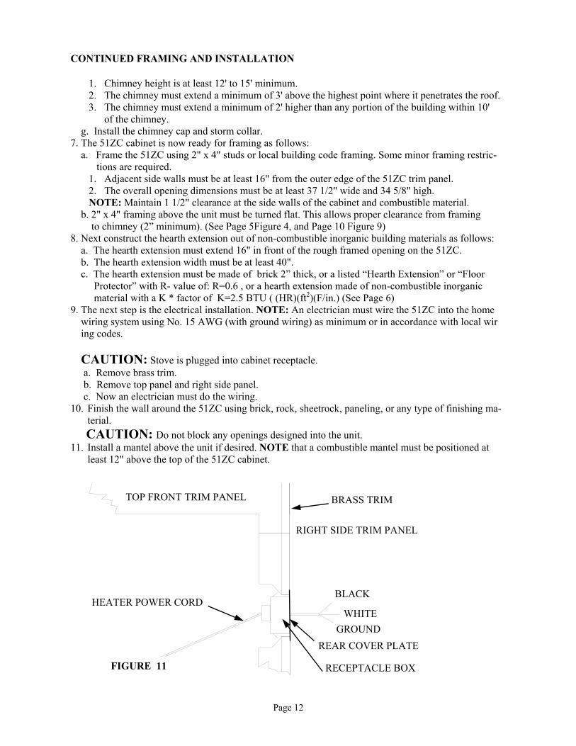
g. Install the chimney cap and storm collar. 7. The 51ZC cabinet is now ready for framing as follows: a. Frame the 51ZC using 2" x 4" studs or local building code framing. Some minor framing restric- tions are required. 1. Adjacent side walls must be at least 16" from the outer edge of the 51ZC trim panel. 2. The overall opening dimensions must be at least 37 1/2" wide and 34 5/8" high. NOTE: Maintain 1 1/2" clearance at the side walls of the cabinet and combustible material. b. 2" x 4" framing above the unit must be turned flat. This allows proper clearance from framing to chimney (2” minimum). (See Page 5Figure 4, and Page 10 Figure 9) 8. Next construct the hearth extension out of non-combustible inorganic building materials as follows: a. The hearth extension must extend 16" in front of the rough framed opening on the 51ZC. b. The hearth extension width must be at least 40". c. The hearth extension must be made of brick 2” thick, or a listed “Hearth Extension” or “Floor Protector” with R- value of: R=0.6 , or a hearth extension made of non-combustible inorganic material with a K * factor of K=2.5 BTU ( (HR)(ft2)(F/in.) (See Page 6) 9. The next step is the electrical installation. NOTE: An electrician must wire the 51ZC into the home wiring system using No. 15 AWG (with ground wiring) as minimum or in accordance with local wir ing codes.
CAUTION: Stove is plugged into cabinet receptacle. a. Remove brass trim. b. Remove top panel and right side panel. c. Now an electrician must do the wiring. 10. Finish the wall around the 51ZC using brick, rock, sheetrock, paneling, or any type of finishing ma-
terial.
CAUTION: Do not block any openings designed into the unit. 11. Install a mantel above the unit if desired. NOTE that a combustible mantel must be positioned at
least 12" above the top of the 51ZC cabinet.
TOP FRONT TRIM PANEL BRASS TRIM
RIGHT SIDE TRIM PANEL
BLACK
WHITE
GROUND
REAR COVER PLATE
RECEPTACLE BOX
HEATER POWER CORD
FIGURE 11
Page 13
SECTION II
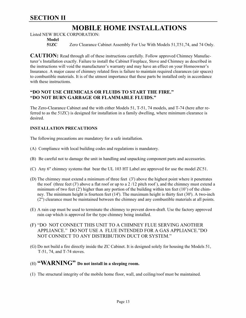
MOBILE HOME INSTALLATIONS Listed NEW BUCK CORPORATION: Model 51ZC Zero Clearance Cabinet Assembly For Use With Models 51,T51,74, and 74 Only.
CAUTION: Read through all of these instructions carefully. Follow approved Chimney Manufac-turer’s Installation exactly. Failure to install the Cabinet Fireplace, Stove and Chimney as described in the instructions will void the manufacturer’s warranty and may have an effect on your Homeowner’s Insurance. A major cause of chimney related fires is failure to maintain required clearances (air spaces) to combustible materials. It is of the utmost importance that these parts be installed only in accordance with these instructions. “DO NOT USE CHEMICALS OR FLUIDS TO START THE FIRE.” “DO NOT BURN GARBAGE OR FLAMMABLE FLUIDS.” The Zero-Clearance Cabinet and the with either Models 51, T-51, 74 models, and T-74 (here after re-ferred to as the 51ZC) is designed for installation in a family dwelling, where minimum clearance is desired. INSTALLATION PRECAUTIONS The following precautions are mandatory for a safe installation. (A) Compliance with local building codes and regulations is mandatory. (B) Be careful not to damage the unit in handling and unpacking component parts and accessories. (C) Any 6" chimney systems that bear the UL 103 HT Label are approved for use the model ZC51. (D) The chimney must extend a minimum of three feet (3') above the highest point where it penetrates
the roof (three feet (3') above a flat roof or up to a 2 /12 pitch roof ), and the chimney must extend a minimum of two feet (2') higher than any portion of the building within ten feet (10’) of the chim-ney. The minimum height is fourteen feet (14'). The maximum height is thirty feet (30'). A two-inch (2") clearance must be maintained between the chimney and any combustible materials at all points.
(E) A rain cap must be used to terminate the chimney to prevent down-draft. Use the factory approved
rain cap which is approved for the type chimney being installed. (F) “DO NOT CONNECT THIS UNIT TO A CHIMNEY FLUE SERVING ANOTHER APPLIANCE.” DO NOT USE A FLUE INTENDED FOR A GAS APPLIANCE.”DO NOT CONNECT TO ANY DISTRIBUTION DUCT OR SYSTEM.” (G) Do not build a fire directly inside the ZC Cabinet. It is designed solely for housing the Models 51, T-51, 74, and T-74 stoves.
(H) “WARNING” Do not install in a sleeping room. ( I ) The structural integrity of the mobile home floor, wall, and ceiling/roof must be maintained.

Page 14
FRAMING CONSTRUCTION AND INSTALLATION
FRAMING CONSTRUCTION AND INSTALLATION
Except as noted, the 51ZC can be installed almost anywhere you desire. There are, however, a few clearance and framing restrictions that must be followed. (See Page 6, Figure 5, and Page 7, Figure 6, also Figure 12) to make sure that these clearance restrictions are met. It is much wiser to place your 51ZC correctly at the start of the installation than to be forced to relocate it after much of the work is done.
You must ensure that the floor is of adequate strength to accept the load of this unit. If inadequate, the floor will require additional support, such as bracing. NOTE: A wooden base constructed of plywood or 2" x 4" boards is required in order to get proper clearance above the extended hearth (millboard, rock, stone, etc.). (See Page 16.)
1. Thoroughly clean the area where the unit will be placed. Remove any carpeting/padding from the area where
the 51ZC will be installed.
2. Layout the location on the floor for ZC cabinet. NOTE: Maintain 3/4" clearance between the rear of the cabinet and combustible material.
CAUTION
THE STRUCTURAL INTEGRITY OF THE MOBILE HOME FLOOR, WALL, AND CEILING/ROOF MUST BE MAINTAINED.
(MOVE OPENING AND/OR REPOSITION HEATER LOCATION IF NECESSARY).
3. Layout for hearth extension preparation and removal of carpet and padding . The hole for the out side air kit may be located anywhere under the 51ZC Cabinet. A 4 1/4" diameter hole with a 2 1/8” radius from center line must be cut through floor. 4" Outside air duct kit # PP70075-01 is to be installed. 4" flex or solid pipe and outside air pipe termination cap ( not provided). Slide the outside air duct down through the hole in the floor, and secure out side air duct with 4 screws (not provided). (See Page 15, Figure 13.) NOTE: The maximum length of the out side air pipe is determined by having to reach the same atmospheric pressure with the out side air inlet as the exhaust. NOTE: “Combustion air inlet ducts shall not terminate in attic spaces
4. Place the sheet safety shield provided with unit 1 1/2" under the front of the cabinet. It must extend out under the floor protector. Drop a plumb line, locate and mark point on ceiling directly over center of 51ZC chimney
adapter. After locating the center of hole, install firestop spacer per chimney manufacturer’s instructions.
26"
INTERIOR LOCATION CORNER LOCATION
26"
FIGURE 12

Page 15
5. Obtain the Listed and Approved Chimney Installation instructions and follow exactly. a) Obtain the starter section of pipe and install on the 51ZC cabinet. It may be necessary to crimp the inside
of the starter pipe to ease installation into the 51ZC cabinet. b) Obtain the two short sheet metal “ell” brackets and sheet metal screws provided with the 51ZC and secure
the starter section of pipe to the 51ZC cabinet. c) Add applicable lengths of chimney extending through the roof until the following conditions are met: 1. The chimney must extend a minimum of 3' above the highest point where it penetrates the roof. 2. The chimney must extend a minimum of 2' higher than any portion of the building within 10' of the chimney but not to exceed 15' above the hearth. d) Install the flashing, storm collar, and chimney cap as indicated in the manufacturer’s installation
instructions. 6. The 51ZC Cabinet is now ready for framing as follows:
a) Frame the 51ZC using 2"x 4" studs or local building code framing. Some minor framing restrictions are required:
1. Adjacent side walls must be at least 17" from the outer edge of the 51ZC trim panel. 2. The overall opening dimensions must be at least 37 1/2" wide and 34 3/4" high. 3. Clearances from mantel, and trim to the top of unit must be a minimum 30.5" (See Page 16, Figure 14).
b) 2" x4" framing above the unit must be turned flat. This allows proper clearance from framing to chimney (2" minimum). (See Page 16, Figure 14).
FIGURE 13
2 ft.
RAIN CAP
STORM COLLAR
FLASHING
NEW BUCK FIRE STOP RADIATION SHIELD
OUTSIDE AIR DUCT THROUGH FLOOR
2 ft.
RAIN CAP
STORM COLLAR
FLASHING
NEW BUCK FIRE STOP RADIATION SHIELD
3 ft. Typical
20 ft. Max. (Typical)
OUTSIDE AIR DUCT THROUGH FLOOR WHEN MOBILE HOME IS NOT UN-DERPINNED
OUTSIDE AIR DUCT THROUGH UNDERPINNING 4" FLEX OR SOLID PIPE
4 " OUTSIDE AIR DUCT MAY BE LOCATED ANY WHERE UNDER 51ZC CABINET
4 " OUTSIDE AIR DUCT MAY BE LOCATED ANY WHERE UNDER 51ZC CABINET
OUTSIDE AIR PIPE TERMINATION CAP ( NOT PROVIDED )

Page 16
7. Next construct the hearth extension out of non-combustible inorganic building materials as follows:
a) The hearth extension must extend 16" in front of the rough framed opening on the 51ZC. b) The hearth extension width must be at least 37 1/2". c) The hearth extension must be made of brick 2" thick, a listed “Hearth Extension” or “Floor Protector”, or
a hearth extension made of non-combustible inorganic material with a K* factor of:
K = 2.5 BTU ((HR) (ft2) (oF/in.)) or R-Value R=0.6 See Page 6 for formula.
ALTERNATE FLOOR PROTECTORS MATERIALS With the floor protector or hearth extension material specified as one layer of 2" thick brick with a K* factor of 5.0, you may use alternate materials as long as the K* factor (s) is calculated as follows: Formula: Required thickness = (K of alternate material/K of millboard) X (thickness of millboard) Example: An alternate inorganic non-combustible millboard with a K of .9375 would require a thickness as follows: Required thickness = .9375.0o x 2 inch = 3/8 inch
FIGURE 14 CHASE ENCLOSURE AND CORNER LOCATION FRAMING
Optional Fire Code Sheet Rock And Metal Fire Stop
Ceiling
RADIATION SHIELD
15FT. MAX.
2 In. Min.
Chase Enclosure
TOPPER
STORM COLLAR
ROOF FLASHING
TRIPLE WALL PIPE
2 " X 4" STUDDING
USE FIRE CODE SHEET ROCK
OPTIONAL METAL FIRE STOP RADIATION SHIELD
2" X 4" STUDDING
A SINGLE HEADER MUST BE INSTALLED ABOVE CABINET
34 3/4"
16"
37 1/2"
THESE MEASUREMENTS ARE CRITICAL
WARNING: Install the hearth protec-tor only as specified. The hearth exten-sion must extend a minimum of 16" in front of the fireplace opening and must be 37 1/2" wide minimum. (See Page 5)
CAUTION: Refer to chim-ney manufacturer’s instruc-tions for assembly and disas-sembly of chimney parts. Be sure to follow chimney instructions for proper clear-ances to combustibles and proper air spacing required.
NOTE: Follow building and fire codes for each individual state.
“A MINIMUM OF 30.5" FROM
TOP OF UNIT TO TRIM OF 30.5"

Page 17
K Factors of Alternate Materials: Material K Required Thickness Ceroform 126 .21 1/8" Limestone 8.0 3.2" Concrete 8.0 3.2" Sandstone 13.0 5.2" Marble 18.0 7.2" Hearth extension or floor protector thickness above four (4) inches is generally not acceptable due to cost, floor load capacity, and look. The alternate we recommend is using Ceroform No. 126 millboard 1/8" thick minimum and putting any type decorative brick or stone (any thickness) on top of it. *The K* factor represents the thermal conductivity of a material and is the time rate of heat flow through a homogeneous material under steady-state conditions, through unit area, per unit temperature gradient in the direction perpendicular to a surface. 9. The next step is the electrical installation. NOTE: An electrician must wire the 51ZC into the home wiring
system using No. 15 AWG (with ground wiring) as minimum in accordance with local wiring codes.
CAUTION: Stove is plugged into cabinet receptacle.
A. Remove brass trim. B. Remove top panel and right side panel. C. Now an electrician must do the wiring.
9. Finish the wall around the 51ZC using brick, rock, sheetrock, paneling, or any type finishing material.
CAUTION: Do not block any openings designed into the unit. 10. Install a mantel above the unit if desired. Note that a combustible mantel must be positioned at least 12" above
the top of the 51ZC cabinet. 11. The 51ZC and Model 51,T51,74 or T-74 fireplace are now ready for use. Refer to the stove owners manual for
operation, safety, and chimney maintenance. Refer to the back of this manual for 51ZC warranty registration information.
FIGURE 15 POWER HOOK-UP
TOP FRONT TRIM PANEL
BRASS TRIM
RIGHT SIDE TRIM PANEL
BLACK
WHITE
GROUND
REAR COVER PLATE
RECEPTACLE BOX
HEATER POWER CORD

Page 18
CLEANING THE UNIT A. The unit should be lightly sanded with fine sandpaper or steel wool, then repainted or touched up with high
temperature black paint. B. If the unit is located in a moist or damp location, check thoroughly for signs of condensation during times
when the unit is not in use. C. When the heating season is over, the unit can be cleaned out completely with a wire brush or cloth to help
eliminate ash and burned wood smell.
SAFETY PRECAUTIONS 1. Use smoke detectors around the stove as well as in sleeping areas. 2. Keep a fire extinguisher rated for Class “A” fires near the stove. 3. Check with your insurance company to be sure your policy covers the installation and use of a wood burning
appliance. 4. Creosote-Formation and Need for Removal: When wood is burned slowly, it produces tar and other organic
vapors, which combine with expelled moisture to form creosote. The creosote vapors condense in the relatively cool chimney flue of a slow-burning fire. As a result, creosote residue accumulates on the flue lining. When ignited this creosote makes an extremely hot fire. The connector and/or chimney should be inspected at least once every two months during the heating season to determine if a creosote buildup has occurred. If creosote has accumulated, it should be removed to reduce the risk of a chimney fire.
5. Locate furniture and any other combustibles away from the stove. 6. Store firewood at a safe distance from the stove. 7. Disposal of Ashes: Ashes should be placed in a metal container with a tight fitting lid. The closed container of
ashes should be placed on a non-combustible floor or on the ground well away from all combustible materials, pending final disposal. If the ashes are disposed of by burial in soil or otherwise locally dispersed, they should be retained in the closed container until all cinders have thoroughly cooled.
8. Always exercise caution when using your fireplace. Be particularly careful when there are children around an
operating fireplace. CAUTION: NEVER use gasoline, gasoline-type lantern fuel, kerosene, charcoal lighter fluid or similar liquids to start or “freshen-up” a fire in the fireplace. Keep all such liquids well away from the stove when it is in use. All fluids of this type give off highly volatile fumes and can and WILL EXPLODE! Don’t take a chance with the safety of your home and family.

Page 19
PREVENTIVE MAINTENANCE/ SAFETY PRECAUTIONS
CHIMNEY A. The chimney should be cleaned as necessary to remove creosote, soot, leaves, bird’s nests, etc.
CREOSOTE-FORMATION AND NEED FOR REMOVAL When wood is burned slowly, it produces tar and other organic vapors, which combine with expelled moisture to form creosote. The creosote vapors condense in the relatively cool chimney flue of a slow-burning fire. As a result, creosote residue accumulates on the flue lining. When ignited this creosote makes an extremely hot fire. The chimney connector and chimney should be inspected at least once every two months. More frequent inspection and cleaning may be necessary. Under certain conditions of use creosote build-up may occur rapidly. Creosote is caused by low temperatures in the chimney, which is controlled by the operator of the stove. B. A neglected chimney can eventually cause a draw restriction or can ignite and burn hot enough to cause
damage to the chimney. C. For proper inspection the chimney should be cleaned.
CHIMNEY CLEANING: 1. Access-Chimneys must be installed so that access is provided for inspection and cleaning. 2. When to Clean-The chimney should be inspected at least once every two months during the heating season to
determine if creosote or soot has built up. Check spark arrestor screens every 2-4 weeks. If creosote or soot has accumulated, it should be removed to reduce the risk of chimney fire.
3. How to Clean-Have your chimney cleaned by a professional chimney sweep if you have doubts about your
ability to clean it, using a plastic, wood, or steel brush. Do not use a brush that will scratch the stainless steel liner of your chimney. Scrub the spark arrestor with a wire brush.
To remove the chimney cap for cleaning, unscrew the four screws that attach the cap’s support legs to the cap base. The top cleanout cap can be removed once the screws are unscrewed. Remember to replace the screws when you are through cleaning the chimney.
4. No Chemical Cleaners-Do not use chemical chimney cleaners. Their use does not eliminate the need for mechanical cleaning and they may be highly corrosive.
5. In Case of Fire-If a flue fire occurs, close all appliance draft openings and call your Fire Department. Do not
use the chimney again until it is inspected for possible damage. 6. Chimney Protection-Painting. To increase chimney life, coat all exterior metal parts with high temperature
rust-proof paint. This is highly recommended, particularly in areas near the ocean. Wash the metal with a vinegar and water solution before painting.

Page 20
4. Remove the access cover door located at the bottom front of the room heater. There are two (2) phil-lips head screws which must be removed, one (1) in each top corner of the access cover door.
5. Next, under the hearth on the left and right sides there are 3/8" head screws which attaches the room heater unit to a bracket (Front Stove Stop) on the ZC cabinet. These two (2) screws must be re-moved at this time.
NOTE: Disconnect the power cord from the receptacle inside the ZC cabinet before removing the Model 51,T-51, 74, T-74 room heater. Do not damage the power cord while pulling the room heater out.
REMOVING MODELS 51, T-51, 74, AND T-74 ROOM HEATER FROM THE
MODEL 51ZC CABINET At some point you may need to remove your Model 51, T-51, 74,T-74 room heater from the Model 51ZC cabinet, if so follow these instruction exactly. Remember if the room heater has been in use allow time for cooling. 1. First remove the seven (7) 5/16" screws from the Top Front Trim. You may need a standard screw-
driver to lift one of the outer corners of the Top Front Trim before being able to remove it. (See Page 22, Figure 18.) 1. Remove the three (3) 5/16" screws from the Right Side Trim. This will enable you to access the
power cord and receptacle, to disconnect the power supply to the room heater. (See Page 22 ,Figure 18.) 1. Located between the room heater and the ZC cabinet is the Flue Connector. On each side of the Flue
Connector there is a threaded rod which is attached to the top of the ZC cabinet and has two (2) 9/16" nuts with a bracket between them that is attached to the Flue Connector. You will first need to run the top nuts up the threaded rod about 1 1/4" (Do this on both the right and left side’s). Next run
TOP ADJUSTMENT NUT
BOTTOM ADJUST-MENT NUT
FLUE CONNEC-TOR SLIP COLLAR BRACKETS
FLUE COLLAR
BRACKETS (FRONT STOVE STOPS)
POWER CORD RECEPTA-CLE
FIGURE 16 AREA BEHIND ACCESS COVER DOOR

Page 21
Continued Removing Room Heater From ZC Cabinet
6. Facing the unit from the front, lift the room heater up and pull out by the front corners of the room heater top. You must lift the room heater up high enough for the bottom to clear the brackets (front stove stops) on the bottom front of the ZC Cabinet. NOTE: If you need more clearance to lift the room heater inside the ZC cabinet at this point you may need to adjust the Flue Connector up more.
BRACKETS (FRONT STOVE STOPS)
REAR STOVE STOPS
OUTSIDE AIR ROD
STOVE SUPPORT RUNNERS
ELECTRICAL BOX AND RECEPTACLE
OUTSIDE AIR INLET
FIGURE 17 MODEL 51ZC CABINET CUTOUT
NOTE: Before pulling the room heater out of the ZC cabinet you may need to place a drop cloth where the heater is to be placed to protect your floor covering.
REINSTALLING THE MODEL 51, T-51, 74, T-74 ROOM HEATER IN THE MODEL 51ZC CABINET
1. First lift the rear of the room heater up and over the front stove stop brackets. The rear of the heater
should rest on the support runners, keep the heater angled with the front lifted up and slide the heater back into the ZC cabinet.
2. Slide the heater back until it stops at the rear stove stops. 3. Next reattach the front stove stop brackets to the heater using the two (2) 3/8" head screws.
NOTE: The front stove stop brackets may have become bent while sliding the heater in and out of the ZC cabinet, if so bend the brackets back in place and reattach as instructed.
4. Now you must reconnect the Flue Connector to the Model 51, T-51, 74, T-74 room heater. Run the bottom nuts down almost to the end of the threaded rod. Align the Flue Connector with the room heater and place it into the Flue collar. At this point you must run the top nuts down until they are tight and the Flue connector is secure into the Flue Collar, then run the bottom nuts back up until they are tight.

Page 22
Continued Reinstalling Room Heater In ZC Cabinet
5. Next reconnect the heater power cord to the ZC cabinet receptacle. 6. Replace the Right Side Trim using the three (3) 5/16" screws. 7. Then replace the Top Front Trim using the seven (7) 5/16" screws.
MODELS 51,T-51,74 or T-74 ROOM HEATERS AND MODEL 51ZC CABINET IDENTIFICATION
(See Figures 16 & 17 For Additional Identification)
(1)
(2)
(3)
(4)
(5)
(6)
(7)
(8)
(9)
(10)
(11)
(23)
(12)
(13)
(14) (15) (16) (17)
(18)
(19) (20)
(21)
(22)
(24)
(25)
(26)
(27)
(28)
(29)
(30)
(31)
(32)
1. 6" Flue Exit 2. Hot Air Vent 3. Top Fire Brick 4. Air Wash 5. Side Brick 6. Outside Trim 7. Door Handle 8. Brass Spring 9. Door Rope 10. Hearth 11. Rheostat 12. Door
13. Glass Clips 14. Second Air Intake 15. Combustion Air Supply Handle 16. Access Cover Door 17. Thermostat 18. Top Front Trim 19. Motor 20. Left & Right Front Trim 21. Bottom Fire Brick 22. Secondary Air Tubes 23. Power Cord
24. Top Outside Trim 25. Glass & Logo 26. Brass Hinge Cap 27. Hinge Pins 28. Hinge Block 29. Optional Side Close Clear-
ance Heat Shield 30. Hearth Brass 31. Left & Right Outside Trim 32. Access Cover Mounting
Screws
FIGURE 18

Page 23
NEW BUCK CORPORATION (NBC) "LIMITED WARRANTY" FOR THE BUCK STOVE
PLEASE READ THIS WARRANTY CAREFULLY
PRODUCTS COVERED This warranty covers the New Buck Stove heating unit, so long as it is owned by the original purchaser, including optional and standard accessories purchased at the same time, subject to terms, limitations, and conditions herein set out. PRODUCTS NOT COVERED This warranty does not cover the following: Glass; Refractory material such as refractory cement or firebrick; Gaskets. This Warranty will also not cover any damage and/or failure caused by abuse or improper installation of the products covered. WARRANTY TIME PERIODS (A) Period I For one year from the date of purchase, NBC will replace or repair, at its option, any part defective in materials or workmanship. The costs of parts only are included. The customer pays any labor or transportation charges required. Thereafter B) Period II For the period after the first year from the date of purchase and extending for 5 years as long as the Buck Stove is owned by the original purchaser, NBC will repair or replace, at its option, any part defective in materials or workmanship, with the exception of: electrical motors, wiring, switches, and components: optional and standard accessories; and all parts not permanently attached to the heating unit. Parts not permanently attached to the heating unit are defined as those items designed to be removed from the stove, including those removable with common hand tools. The costs of parts only are included. The customer pays any labor or transportation charges required. . PROCEDURE Should you feel that your BUCK STOVE is defective, you should contact any Buck Stove dealer for the name of your nearest authorized Buck Stove service representative, who will instruct you on the proper procedure, depending on which Warranty Time Period (Period I or Period II) applies.


If for any reason you are dissatisfied with the suggested procedures, you may contact us in writing at: New Buck Corporation Customer Service Department P. O. Box 69 Spruce Pine, NC 28777 CONDITIONS AND EXCLUSIONS A. Replacement of parts may be in the form of new or fully reconditioned parts, at NBC's
option. B There is no other express warranty. All implied warranties of Merchantability and
Fitness for Use are limited to the duration of the Express Warranty. C. New Buck Corporation is not liable for indirect, incidental, or consequential damages in
connection with the use of the product including any cost or expense of providing substitute equipment or service during periods of malfunction or non-use.
Some states do not allow the exclusion of incidental or consequential damages, so the above exclusion may not apply to you. D. All warranty repairs under this warranty must be performed by an
authorized Buck Stove service representative. Repairs or attempted repairs by anyone other than an authorized service representative are not covered under this warranty. In addition, these unauthorized repairs may result in additional malfunctions, the correction of which is not covered by warranty.
OTHER RIGHTS This warranty gives you specific legal rights, and you may also have other rights, which vary from state to state. OWNER REGISTRATION CARD The attached Owner Registration Card must be completed in entirety and mailed within 30 days from the date of purchase or from the date of installation, if installed by a factory certified installer, to New Buck Corporation in order for warranty coverage to begin. PLEASE NOTE: The Owner Registration Card must contain the Authorized Buck Stove Dealer Code Number and the Certified Installer's number (if applicable) for warranty coverage to begin. To be completed by selling distributor or dealer for customer: Warranty Card Not Available On Replacement Or Online Manuals