HZD1500 Bin Blender Product Manual -SaintyCo
39
HZD1500 Bin Blender Product Manual Serial No: 170205 Year of Mfg: 2017.02 Thank you for using the HZD1500 Bin Blender manufactured by SAINTYCO. The equipment is manufactured according to the industry standard 《JB20011-2004》 and company standard《Q/BJN02-2001》.]
-
Upload
tony-zeng -
Category
Health & Medicine
-
view
106 -
download
7
Transcript of HZD1500 Bin Blender Product Manual -SaintyCo

HZD1500 Bin BlenderProduct Manual
Serial No: 170205
Year of Mfg: 2017.02
Thank you for using the HZD1500 Bin Blender manufactured by
SAINTYCO. The equipment is manufactured according to the industry
standard《JB20011-2004》 and company standard《Q/BJN02-2001》.]

HZD SERIES BIN BLENDER
SanityCo Internaltional Group
Please read this manual before installing and using. If you do not abide by this manual, it can
result in human hurt, machine damages or other losses that we won’t be responsible for. If
you have any question, please contact us, we will provide you warm and fast service.
This manual mainly describes the structure features, working principle, installation &debugging, operation & maintenance, failure analysis & solutions, delivery, storage,etc…Material reports for the contact parts, technical documents of main electric components (e.g.reducer, inverter) and so on will be provided with the machine as the terms of documents.
This manual is only suitable for HZD1500 Bin Blender. Some attached product images and otherimages like menu screenshots in this Manual may have some differences with this actual product,operate according to the real product.
In the precondition that user abides by the Maintenance and Operation regulations and withinthe 12 months after debugging and validation of this equipment, if in case of manufacturingreasons and the equipment cannot operate, we would provide you free repair and changeservices.
The technology of our company’s products will be innovated continuously; the Product Manual will bemodified accordingly. Further modifications are not notified.
HZD SERIES BIN BLENDER
SanityCo Internaltional Group
Table of ContentsForeword.......................................................................................................................................................... 1
0 Keynotes.................................................................................................................................................. 4
1 Safety introduction..................................................................................................................................4
1.0 General description...............................................................................................................................4
1.1 Transport and Storage..........................................................................................................................5
1.2 Installation & Debugging......................................................................................................................5
1.3 Usage and maintenance......................................................................................................................6
2 Equipment General Description.........................................................................................................6
2.0 General Description.............................................................................................................................. 6
2.1 Product Features...................................................................................................................................6
2.2 Product model specification and its signification............................................................................. 7
2.3 Applicable environment and Working conditions.............................................................................7
2.4 Environment Impact..............................................................................................................................7
3 Structure features and working principle..........................................................................................8
3.0 General Description.............................................................................................................................. 8
3.1 Bin............................................................................................................................................................8
3.2 Lifting system......................................................................................................................................... 9
3.3 Rotary system......................................................................................................................................10
3.4 Composition and principle of the electric control system.............................................................11
3.5 Working principle.................................................................................................................................12
4 Outline dimensions and main technical parameters.................................................................... 13
4.1 Outline diagram...................................................................................................................................13
4.2 Main technical parameters................................................................................................................ 14
5 Installation and Debugging...............................................................................................................14
5.1 Installation foundation........................................................................................................................ 14
5.2 Technical requirements for installation............................................................................................14
5.3 Installation............................................................................................................................................ 15
5.4 Installation of machine parts............................................................................................................. 17
5.5 Debugging procedures, methods and points for attention...........................................................17
HZD SERIES BIN BLENDER
SanityCo Internaltional Group
6 Equipment Operation...........................................................................................................................20
6.1 Preparations before starting the equipment...................................................................................21
6.2 Equipment start up and Operation procedures and methods..................................................... 21
7 Trouble shooting and analysis............................................................................................................31
7.1 Failure of the control system.............................................................................................................32
7.2 Failure of the mechanical transmission system.............................................................................33
8 Maintenance..........................................................................................................................................34
8.0 Summary.............................................................................................................................................. 34
8.1 Daily Maintenance.............................................................................................................................. 34
8.2 Maintenance in case of long time storage......................................................................................36
8.3 Other......................................................................................................................................................36
9 Lubrication...........................................................................................................................................37
10 Transportation and storage.............................................................................................................. 37
10.1 Package..............................................................................................................................................38
10.2 Transportation....................................................................................................................................38
10.3 Storage............................................................................................................................................... 38
11 Unpacking and Checking..................................................................................................................38
11.1 Unpacking attentions........................................................................................................................38
11.2 Items Checking..................................................................................................................................38
Attachment 1: Outline dimensions drawing
Attachment 2: Installation foundation drawing
Appendix:Electric diagram
HZD SERIES BIN BLENDER
SanityCo Internaltional Group
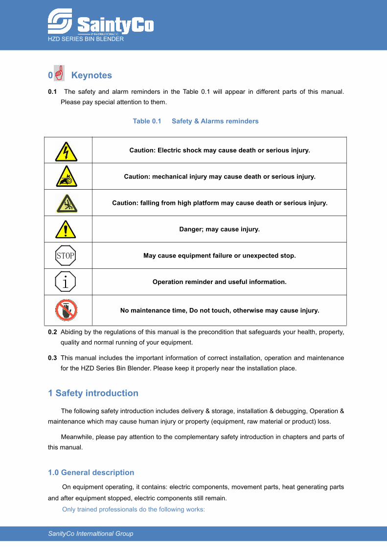
0 Keynotes0.1 The safety and alarm reminders in the Table 0.1 will appear in different parts of this manual.
Please pay special attention to them.
Table 0.1 Safety & Alarms reminders
Caution: Electric shock may cause death or serious injury.
Caution: mechanical injury may cause death or serious injury.
Caution: falling from high platform may cause death or serious injury.
Danger; may cause injury.
May cause equipment failure or unexpected stop.
Operation reminder and useful information.
No maintenance time, Do not touch, otherwise may cause injury.
0.2 Abiding by the regulations of this manual is the precondition that safeguards your health, property,quality and normal running of your equipment.
0.3 This manual includes the important information of correct installation, operation and maintenancefor the HZD Series Bin Blender. Please keep it properly near the installation place.
1 Safety introduction
The following safety introduction includes delivery & storage, installation & debugging, Operation &maintenance which may cause human injury or property (equipment, raw material or product) loss.
Meanwhile, please pay attention to the complementary safety introduction in chapters and parts ofthis manual.
1.0 General description
On equipment operating, it contains: electric components, movement parts, heat generating parts
and after equipment stopped, electric components still remain.
Only trained professionals do the following works:
STOP
i
HZD SERIES BIN BLENDER
SanityCo Internaltional Group
Transport
Storage
Installation/Assembly
Operation
Maintenance
Please read the following documents before doing the above works: Attached drawings
Other documents furnished with the machine
Equipment mark plate
Special regulations and requirements relative to the equipment.
Country or regional regulation relative to safety and prevention of accidents
The following situations will cause serious injury and property loss.
Incorrect convey
Incorrect installation
Incorrect use or operation
Removal of necessary safety protection devices without authorization
1.1 Transport and Storage
Check the product’s safety during the shipping. On arrival, the product should be free of breachotherwise inform shipping company and SAINTYCO, this is the precondition of claim.
Please strictly abide by relative convey regulations to avoid damaging the equipment or humanhurting.
The devices should be lubricated and anti-rust treated in case of long time storage. All thesemeasures must be done according to the regulations. Protection of the electric control cabinetmust be especially well done.
1.2 Installation & Debugging Please read carefully points relative to the equipment installation of this manual.
This equipment must be unpacked and installed by SAINTYCO or qualified personnel from theagent. Please do not unpack the package case; it is one precondition of claiming forcompensation.
During debugging process, in case of any abnormal phenomenon such as vibration, noise,temperature rise out of range, etc... Operator must stop the machine immediately, check andeliminate the cause.

HZD SERIES BIN BLENDER
SanityCo Internaltional Group
1.3 Usage and maintenance
The equipment consists of electric components, rotating components, straight reciprocating
motion parts, negative pressure bearing parts, high operation platform. Please strictly abide by
the regulations of this manual, thus avoid electric shock, mechanical injure or fall injury during
the operation.
During operation process, in case of any abnormal phenomenon such as vibration, noise,
temperature rise out of range, etc... Operator must stop the machine immediately, check and
eliminate the cause, if necessary please contact us.
Equipment cleaning process may involve electric components, chemical liquid or high
temperature liquid. Please strictly abide by the regulations of this manual, thus avoid electric
shock, corrosion or high temperature burns.
Equipment maintenance process may involve electric components, chain drives and
mechanical spare parts. Please strictly abide by the regulations of this manual, thus avoid
electric shock, mechanical or hit injury.
2 Equipment General Description2.0 General Description
lender is all in-one electromechanical equipment with PLC program control technique. It is mainlyused in pharmaceutical industry for blending solid granules with powder, granules with granules,powder with powder; and is also used in food industry and fine chemical industry in their powdermaterial production process. The equipment has strong points as high blending efficiency and result, aneasy bin changing process and there is not any cross pollution or dust pollution during the process.
2.1 Product Features
2.1.1 PLC and inverter control system are used to carry out procedure control, stable performance andreliable operation.
2.1.2 HMI adopts touch panel, human friendly interface and clear menus, and can be easily operated.High degree of auto-immunization, in one setting; the whole procedure can be accomplished: lifting ofbin, blending and falling of bin. Different control modes are set and can be switched in the program:auto, manual controls.
2.1.3 Set with high capacity storage of parameters, 50 groups of technical parameters of differentmaterials can be stored; when operating, the necessary parameters can be directly called.
2.1.4 One main machine can be configured with multi-bins, so different batches and requirements forvarietal blending can be satisfied. It is propitious to the strict management of batch number.
HZD SERIES BIN BLENDER
SanityCo Internaltional Group
2.1.5 Stable and reliable performances of Infrared photoelectric sensors are adopted to form the mainsafety protection devices. They can safeguard operator’s safety on equipment operation time efficiently.
2.2 Product model specification and its signification
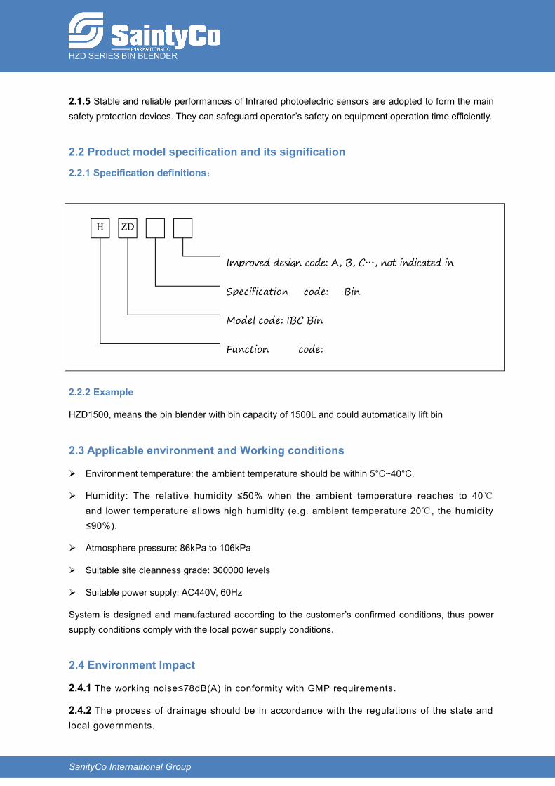
2.2.1 Specification definitions:
2.2.2 Example
HZD1500, means the bin blender with bin capacity of 1500L and could automatically lift bin
2.3 Applicable environment and Working conditions
Environment temperature: the ambient temperature should be within 5°C~40°C.
Humidity: The relative humidity ≤50% when the ambient temperature reaches to 40℃and lower temperature allows high humidity (e.g. ambient temperature 20℃, the humidity≤90%).
Atmosphere pressure: 86kPa to 106kPa
Suitable site cleanness grade: 300000 levels
Suitable power supply: AC440V, 60Hz
System is designed and manufactured according to the customer’s confirmed conditions, thus powersupply conditions comply with the local power supply conditions.
2.4 Environment Impact
2.4.1 The working noise≤78dB(A) in conformity with GMP requirements.
2.4.2 The process of drainage should be in accordance with the regulations of the state andlocal governments.
Improved design code: A, B, C…, not indicated in
H ZD
Specification code: Bin
Model code: IBC Bin
Function code:
HZD SERIES BIN BLENDER
SanityCo Internaltional Group
2.4.3 Equipment scrapping
When the equipment is discarded as useless, the useless parts treatment should inaccordance with the local laws and regulations, and the parts of the equipment which can berecycled, see below:
Main frame, motor housing, body of oil cylinder, piston, etc. can be used as scrapiron.
Container and the stainless steel cover as scrap stainless steel.
The coil of motor as scrap copper.
Other plastic material as scrap plastic
3 Structure features and working principle
3.0 General Description
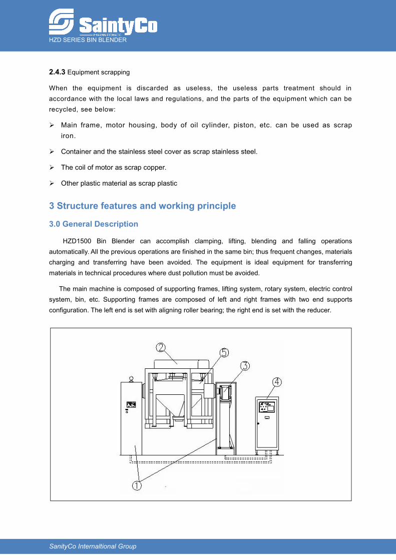
HZD1500 Bin Blender can accomplish clamping, lifting, blending and falling operationsautomatically. All the previous operations are finished in the same bin; thus frequent changes, materialscharging and transferring have been avoided. The equipment is ideal equipment for transferringmaterials in technical procedures where dust pollution must be avoided.
The main machine is composed of supporting frames, lifting system, rotary system, electric controlsystem, bin, etc. Supporting frames are composed of left and right frames with two end supportsconfiguration. The left end is set with aligning roller bearing; the right end is set with the reducer.

HZD SERIES BIN BLENDER
SanityCo Internaltional Group
3.1 Bin
The bin (Pic 3-2a) is composed of bin body, bin lid and its clamp, pressing block, butterfly valve,etc… (Two models of bins, with casters and without caster, can be configured according to customer’srequirements) As is in direct contact with material, the bin adopts low carbon austenitic stainless steel,all corners are streamline designed, no dead angle, easy for washing. Silicon is as seals material forthe lid and discharging butterfly. These structures of the bin could protect medicine from pollution andcross-pollution.
Operation of charging butterfly valve, as Pic3-2b: pull out valve plate location pin along with thearrow direction and rotate, then pull the handle could open butterfly valve; close according to thereversed sequence.
Loading and unloading of bin lid as Pic3-2c, release the clamp along with arrow direction and makelock catch dropout, take away the clamp and lid, assemble the lid according to the reversed sequence.
Pic.3-2a
Pic.3-2b Pic.3-2c
HZD SERIES BIN BLENDER
SanityCo Internaltional Group
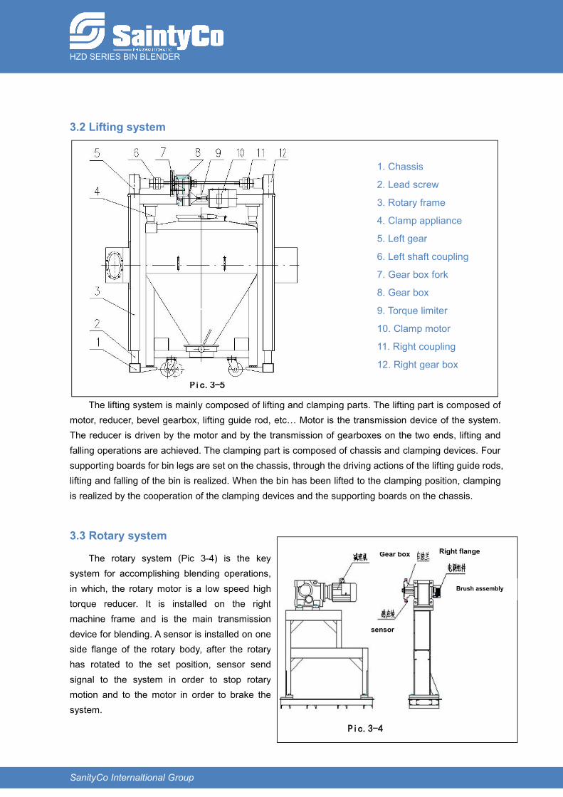
3.2 Lifting system
The lifting system is mainly composed of lifting and clamping parts. The lifting part is composed ofmotor, reducer, bevel gearbox, lifting guide rod, etc… Motor is the transmission device of the system.The reducer is driven by the motor and by the transmission of gearboxes on the two ends, lifting andfalling operations are achieved. The clamping part is composed of chassis and clamping devices. Foursupporting boards for bin legs are set on the chassis, through the driving actions of the lifting guide rods,lifting and falling of the bin is realized. When the bin has been lifted to the clamping position, clampingis realized by the cooperation of the clamping devices and the supporting boards on the chassis.
3.3 Rotary system
The rotary system (Pic 3-4) is the keysystem for accomplishing blending operations,in which, the rotary motor is a low speed hightorque reducer. It is installed on the rightmachine frame and is the main transmissiondevice for blending. A sensor is installed on oneside flange of the rotary body, after the rotaryhas rotated to the set position, sensor sendsignal to the system in order to stop rotarymotion and to the motor in order to brake thesystem.
Pic.3-4
Right flange
Brush assembly
sensor
Gear box
1. Chassis
2. Lead screw
3. Rotary frame
4. Clamp appliance
5. Left gear
6. Left shaft coupling
7. Gear box fork
8. Gear box
9. Torque limiter
10. Clamp motor
11. Right coupling
12. Right gear box
Pic.3-5

HZD SERIES BIN BLENDER
SanityCo Internaltional Group
3.4 Composition and principle of the electric control system
3.4.1 Composition of the electric control system
The electric control system is mainly composed of electric cabinet (Pic 3-5) and sensors. In thismachine, sensors are photoelectric switches, proximity switches, limit switches. The core control partsPLC (① in Pic 3-5) and inverter (16 in Pic 3-5) are installed in the electric control cabinet. In theoperation process, electric operations are accomplished on the operation panel installed on the electriccontrol cabinet (Pic 3-6), in the Picture 3-6, ①②③④ are respectively printer, touch panel, power switchand emergency switch.
3.4.2 Electric control system
a) Lifting operation
When the two conditions for lifting or falling operation (rotary body on horizontal level and bin inposition) are satisfied simultaneously, the main machine will receive the relative signal, controller willsend lifting or falling signal to the lifting/falling motor. Then the motor operates the reducer and thenreducer will drive the lifting/falling screw poles and lifting/falling operation is realized. Signal for limitpositions of lifting and falling limit positions are sent by the limit switches to the controller.
1 PLC DO2 power socket3 PLC main module4、5 relay6、7 breaker8、9 safety fuse10 pressure switch11 transformer12 switch power13 air filter14 inverter15~18 contactor19、20 thermal relay
1 2 3
4
Pic.3-6
Pic.3-5
HZD SERIES BIN BLENDER
SanityCo Internaltional Group
b) Rotary operation
The rotary operation system is composed of inverter and motor. The inverter, after receiving theinput numeric signal of the PLC, transforms its output frequency to adjust the rotation speed of themotor.
c) Rotary positioning
When need to stop and position the bin, follow the steps below for positioning and stopping:
1. After blending time has been reached, main machine rotates at 3 rpm
2. When proximity switch operates, firstly motor power is cut off, the motor braking device brakesand the rotary body is stopped on the horizontal level.
3.4.3 Safety control loop
a)Emergency stop loop
The emergency stop loop of the system is composed of emergency stop switch, emergency stoprelay. When the emergency stop is pressed, the emergency stop loop is opened, system stopsoperating. To restart operating, confirm the safety of the system and then release all emergency stops.
b)Torque limiter
When the lifting/falling torque exceeds the pre-set value, the limiter operates and sends stop signaland transmits sound alarm. At this time, check all the reasons of failures according to contentsdisplayed on the touch panel, then eliminate the failures to restart operating.
c)Infrared photoelectric protection loop of the equipment operating area
The equipment operating area is isolated from the operator’s operating area by an infraredphotoelectric protection device. The safety protection loop is composed of a pair of face to faceinstalled infrared photoelectric protection switches; the state of photoelectric switches is fed back toPLC directly. On equipment auto operating, if anyone or anything enters the equipment operating area,signal is fed back to PLC and the PLC emits order to stop operation immediately in order to protectoperator or equipment safety.
3.4.4 Electric principle drawing, please see attachment.
3.5 Working principle
On operating and the bin has been loaded on the four supporting legs located on the chassis of theblending frame, position the bin and finally photoelectric switches located inside the two supportingframes receive signals for bin in position. After starting the auto operation procedure, the lifting systemlift the bin according to the fixed speed and when the bin starts to touch the clamping devices, the binbegins to be clamped step by step, when the pre-set clamping pressure reached, sensors located onthe clamping devices send signals to the system to stop clamping operation. Then the rotation systembegins operating blending process according to the preset rotation speed and blending time, on ending
HZD SERIES BIN BLENDER
SanityCo Internaltional Group
of the blending process, main machine stops automatically and emits light and sound alarms to remindoperator. Blending procedure finished, PLC emits signal for falling the bin, the lifting system falls the binaccording to the preset speed and when it touches the ground, sensors located on the ground side ofthe chassis emit signals to stop falling operation. A whole blending procedure has been finished; theprinter prints records according to the preset items and parameters.
This machine has been designed with intelligent protection feature, if infrared photoelectricsensors are not released, system cannot operate; if there’s not any bin or if the bin is not in position,lifting system doesn’t operate; if the bin clamping pressure exceeds the pre-set value, machine stopsautomatically; and when the bin has fallen to the ground, machine stops automatically.
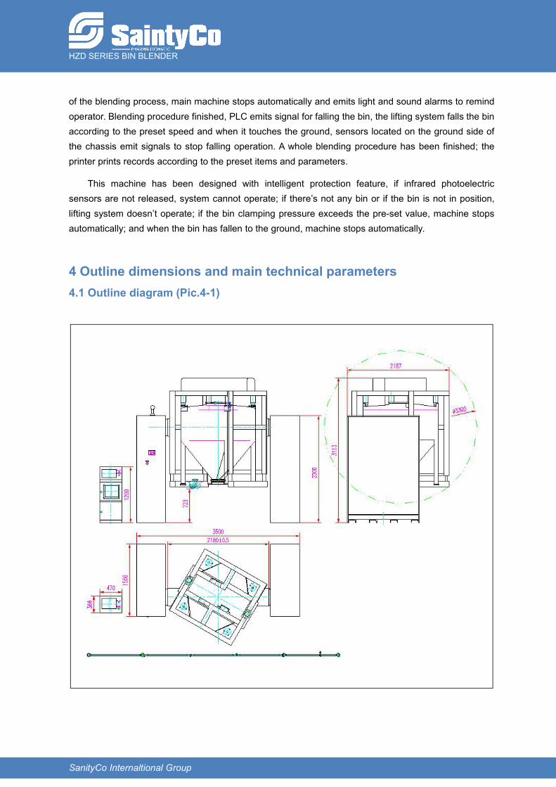
4 Outline dimensions and main technical parameters4.1 Outline diagram (Pic.4-1)
HZD SERIES BIN BLENDER
SanityCo Internaltional Group
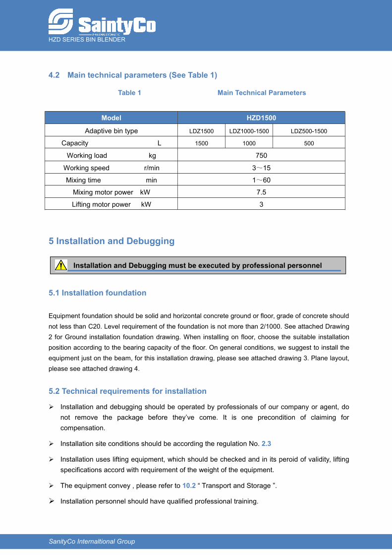
4.2 Main technical parameters (See Table 1)
Table 1 Main Technical Parameters
Model HZD1500
Adaptive bin type LDZ1500 LDZ1000-1500 LDZ500-1500
Capacity L 1500 1000 500
Working load kg 750
Working speed r/min 3~15
Mixing time min 1~60
Mixing motor power kW 7.5
Lifting motor power kW 3
5 Installation and Debugging
5.1 Installation foundation
Equipment foundation should be solid and horizontal concrete ground or floor, grade of concrete shouldnot less than C20. Level requirement of the foundation is not more than 2/1000. See attached Drawing2 for Ground installation foundation drawing. When installing on floor, choose the suitable installationposition according to the bearing capacity of the floor. On general conditions, we suggest to install theequipment just on the beam, for this installation drawing, please see attached drawing 3. Plane layout,please see attached drawing 4.
5.2 Technical requirements for installation
Installation and debugging should be operated by professionals of our company or agent, donot remove the package before they’ve come. It is one precondition of claiming forcompensation.
Installation site conditions should be according the regulation No. 2.3
Installation uses lifting equipment, which should be checked and in its peroid of validity, liftingspecifications accord with requirement of the weight of the equipment.
The equipment convey , please refer to 10.2 “ Transport and Storage ”.
Installation personnel should have qualified professional training.
Installation and Debugging must be executed by professional personnel
HZD SERIES BIN BLENDER
SanityCo Internaltional Group
5.3 Installation
Provided grounding label place, connect it correctly. Test the grounding path way, reading dataless than 4Ω. Correct it if needed.
Before installing, check the hoisting equipment is suitable. This equipment must have effective testcertificate.
Do not use intertwist rope, damaged rope or knotted rope!
Do not use damaged or not adapted tools.
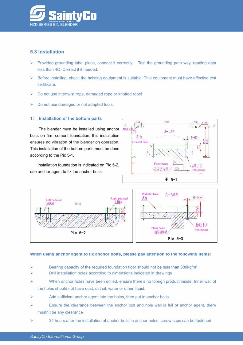
1) Installation of the bottom parts
The blender must be installed using anchorbolts on firm cement foundation; this installationensures no vibration of the blender on operation.This installation of the bottom parts must be doneaccording to the Pic 5-1.
Installation foundation is indicated on Pic 5-2,use anchor agent to fix the anchor bolts.
When using anchor agent to fix anchor bolts, please pay attention to the following items:
Bearing capacity of the required foundation floor should not be less than 800kg/m² Drill installation holes according to dimensions indicated in drawings
When anchor holes have been drilled, ensure there’s no foreign product inside. Inner wall of
the holes should not have dust, dirt oil, water or other liquid,
Add sufficient anchor agent into the holes, then put in anchor bolts
Ensure the clearance between the anchor bolt and hole wall is full of anchor agent, there
mustn’t be any clearance
24 hours after the installation of anchor bolts in anchor holes, screw caps can be fastened
图 5-1
Floor beam
Iron gasket
Pedestal base
Pic.5-3
Iron gasketFloor beam
Pedestal base
Pic.5-2
Left pedestal Right pedestal
HZD SERIES BIN BLENDER
SanityCo Internaltional Group
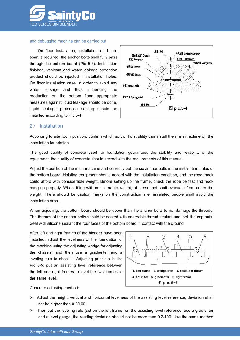
and debugging machine can be carried out
On floor installation, installation on beamspan is required; the anchor bolts shall fully passthrough the bottom board (Pic 5-3). Installationfinished, vesicant and water leakage protectionproduct should be injected in installation holes.On floor installation case, in order to avoid anywater leakage and thus influencing theproduction on the bottom floor, appropriatemeasures against liquid leakage should be done,liquid leakage protection sealing should beinstalled according to Pic 5-4.
2) Installation
According to site room position, confirm which sort of hoist utility can install the main machine on theinstallation foundation.
The good quality of concrete used for foundation guarantees the stability and reliability of theequipment; the quality of concrete should accord with the requirements of this manual.
Adjust the position of the main machine and correctly put the six anchor bolts in the installation holes ofthe bottom board. Hoisting equipment should accord with the installation condition, and the rope, hookcould afford with considerable weight. Before setting up the frame, check the rope tie fast and hookhang up properly. When lifting with considerable weight, all personnel shall evacuate from under theweight. There should be caution marks on the construction site; unrelated people shall avoid theinstallation area.
When adjusting, the bottom board should be upper than the anchor bolts to not damage the threads.The threads of the anchor bolts should be coated with anaerobic thread sealant and lock the cap nuts.Seal with silicone sealant the four faces of the bottom board in contact with the ground,
After left and right frames of the blender have beeninstalled, adjust the levelness of the foundation ofthe machine using the adjusting wedge for adjustingthe chassis, and then use a gradienter and aleveling rule to check it. Adjusting principle is likePic 5-5: put an assisting level reference betweenthe left and right frames to level the two frames tothe same level.
Concrete adjusting method:
Adjust the height, vertical and horizontal levelness of the assisting level reference, deviation shallnot be higher than 0.2/100.
Then put the leveling rule (set on the left frame) on the assisting level reference, use a gradienterand a level gauge, the reading deviation should not be more than 0.2/100. Use the same method
1. lleft frame 2. wedge iron 3. assistont dotum
4. flot ruter 5. gradienter 6. right frame
图 pic.5-5
图 pic.5-4

HZD SERIES BIN BLENDER
SanityCo Internaltional Group
for the right frame. After the two sides have been adjusted, the concentricity of the left side supporting frame and
the right side reducer has to be adjusted: ①measure the diagonal lengths on the horizontalplane between the left flange to the right flange, deviation should not be more than 0.5mm;②distance between the two flanges: measure the distance between the two flanges sides onthe horizontal plane, deviation should be controlled inside ±0.5mm.
Fasten anchor bolts, install rotary body, turn the rotary body manually, bearings of the twosides should not be eccentric and should not have scratching noise.
Note: before turning the rotary body manually, if a manual brake handle is provided, the handleshould be put on the loosening position; if the manual braking handle is not provided, the innerhexagonal screw located on the tail section of the braking motor of the reducer should befastened, then loosen the braking device and adjust it. After adjustment, loosen the hexagonalscrew to recover braking function.
5.4 Installation of machine parts
Due to packing and transportation requirements, equipment parts or components should bereinstalled on installation site, for the second installation, please refer to Chapter 3 “Structure features”.
Installation procedure of the whole body as the following picture:
5.5Debugging procedures, methods and points for attention
This machine shall be debugged by professional personnel!
Calibrated and certificated instruments shall be used for debuggingprocedures!
Debugging shall be executed according to the following order:
1)Checking before debugging
2)Debugging of electric sensor systems
3)Setting of machine operation parameters
Loosenbrakingdevice
Adjustlevelness
Installframes ofthe wholemachine
Install and fastenanchor bolts
Confirminstallationfoundation
Drillholes
Confirmthe
installation
Install theother parts
HZD SERIES BIN BLENDER
SanityCo Internaltional Group
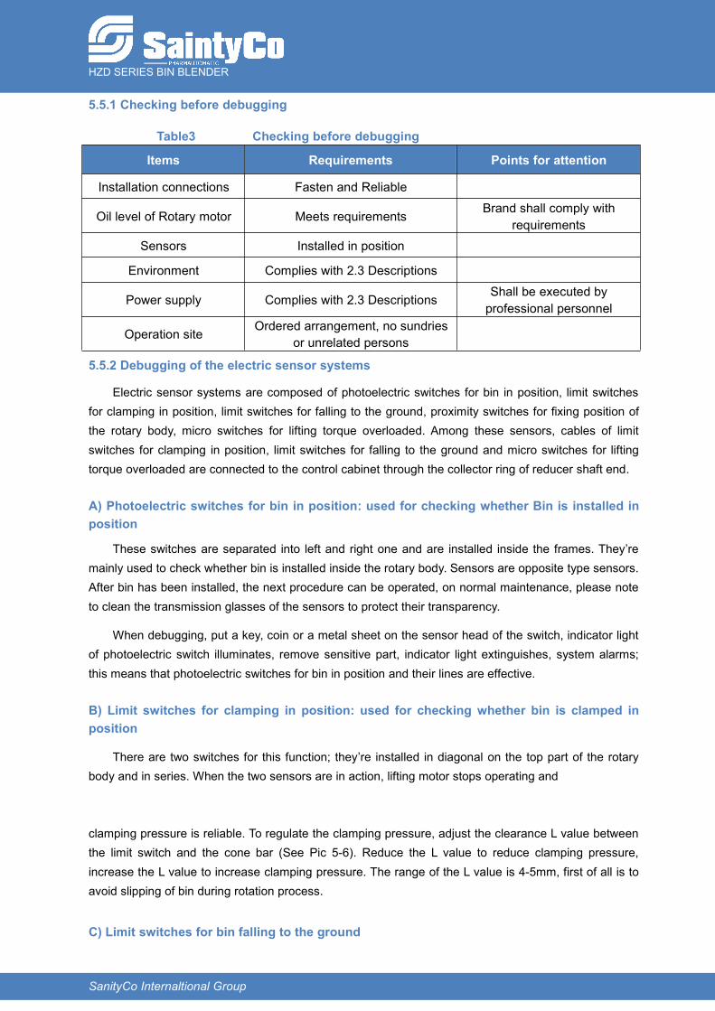
5.5.1 Checking before debugging
Table3 Checking before debugging
Items Requirements Points for attention
Installation connections Fasten and Reliable
Oil level of Rotary motor Meets requirements Brand shall comply withrequirements
Sensors Installed in position
Environment Complies with 2.3 Descriptions
Power supply Complies with 2.3 Descriptions Shall be executed byprofessional personnel
Operation site Ordered arrangement, no sundriesor unrelated persons
5.5.2 Debugging of the electric sensor systems
Electric sensor systems are composed of photoelectric switches for bin in position, limit switchesfor clamping in position, limit switches for falling to the ground, proximity switches for fixing position ofthe rotary body, micro switches for lifting torque overloaded. Among these sensors, cables of limitswitches for clamping in position, limit switches for falling to the ground and micro switches for liftingtorque overloaded are connected to the control cabinet through the collector ring of reducer shaft end.
A) Photoelectric switches for bin in position: used for checking whether Bin is installed inposition
These switches are separated into left and right one and are installed inside the frames. They’remainly used to check whether bin is installed inside the rotary body. Sensors are opposite type sensors.After bin has been installed, the next procedure can be operated, on normal maintenance, please noteto clean the transmission glasses of the sensors to protect their transparency.
When debugging, put a key, coin or a metal sheet on the sensor head of the switch, indicator lightof photoelectric switch illuminates, remove sensitive part, indicator light extinguishes, system alarms;this means that photoelectric switches for bin in position and their lines are effective.
B) Limit switches for clamping in position: used for checking whether bin is clamped inposition
There are two switches for this function; they’re installed in diagonal on the top part of the rotarybody and in series. When the two sensors are in action, lifting motor stops operating and
clamping pressure is reliable. To regulate the clamping pressure, adjust the clearance L value betweenthe limit switch and the cone bar (See Pic 5-6). Reduce the L value to reduce clamping pressure,increase the L value to increase clamping pressure. The range of the L value is 4-5mm, first of all is toavoid slipping of bin during rotation process.
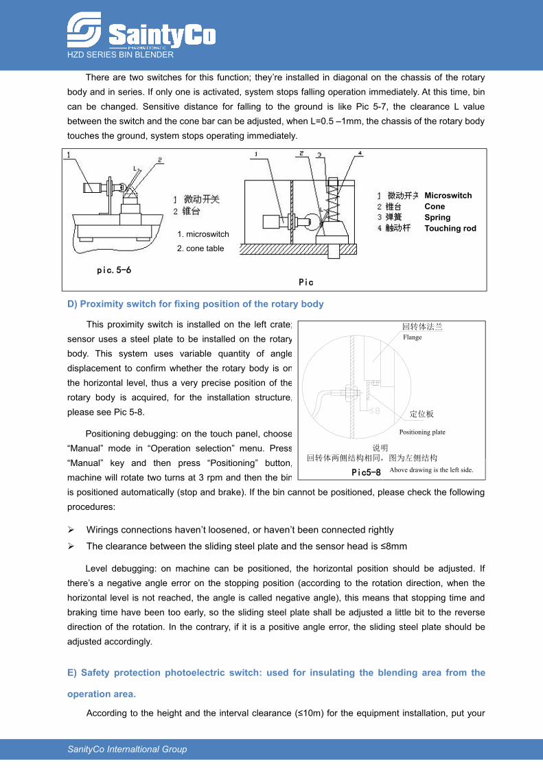
C) Limit switches for bin falling to the ground
HZD SERIES BIN BLENDER
SanityCo Internaltional Group
There are two switches for this function; they’re installed in diagonal on the chassis of the rotarybody and in series. If only one is activated, system stops falling operation immediately. At this time, bincan be changed. Sensitive distance for falling to the ground is like Pic 5-7, the clearance L valuebetween the switch and the cone bar can be adjusted, when L=0.5 –1mm, the chassis of the rotary bodytouches the ground, system stops operating immediately.
D) Proximity switch for fixing position of the rotary body
This proximity switch is installed on the left crate;sensor uses a steel plate to be installed on the rotarybody. This system uses variable quantity of angledisplacement to confirm whether the rotary body is onthe horizontal level, thus a very precise position of therotary body is acquired, for the installation structure,please see Pic 5-8.
Positioning debugging: on the touch panel, choose“Manual” mode in “Operation selection” menu. Press“Manual” key and then press “Positioning” button,machine will rotate two turns at 3 rpm and then the binis positioned automatically (stop and brake). If the bin cannot be positioned, please check the followingprocedures:
Wirings connections haven’t loosened, or haven’t been connected rightly
The clearance between the sliding steel plate and the sensor head is ≤8mm
Level debugging: on machine can be positioned, the horizontal position should be adjusted. Ifthere’s a negative angle error on the stopping position (according to the rotation direction, when thehorizontal level is not reached, the angle is called negative angle), this means that stopping time andbraking time have been too early, so the sliding steel plate shall be adjusted a little bit to the reversedirection of the rotation. In the contrary, if it is a positive angle error, the sliding steel plate should beadjusted accordingly.
E) Safety protection photoelectric switch: used for insulating the blending area from the
operation area.
According to the height and the interval clearance (≤10m) for the equipment installation, put your
pic.5-6
1. microswitch
2. cone table
Pic
5-7
MicroswitchConeSpringTouching rod
回转体法兰
定位板
说明 回转体两侧结构相同,图为左侧结构
Pic5-8
Positioning plate
Flange
Above drawing is the left side.
HZD SERIES BIN BLENDER
SanityCo Internaltional Group
hand between the photoelectric sensors, system should alarm, remove your hand, failure has beeneliminated after confirmation and this means that the photoelectric sensors and their lines are effective.
F) Emergency stop switch
Release the emergency stop switch and turn power switch (key switch) to ON position, the powerindicator light illuminates indicating the system is powered on. Press the emergency stop switch, systemalarms, release the emergency stop, failure has been eliminated after confirmation and this means theemergency stop and its line are effective.
5.5.3 Determination of the whole machine parameters
On finishing the above debugging, determination of the whole machine parameters can be done inexecuting “Auto” mode operation. The following two items of the whole machine parameters areprovided: working time and working speed, for adjustments, please see 6.2.4
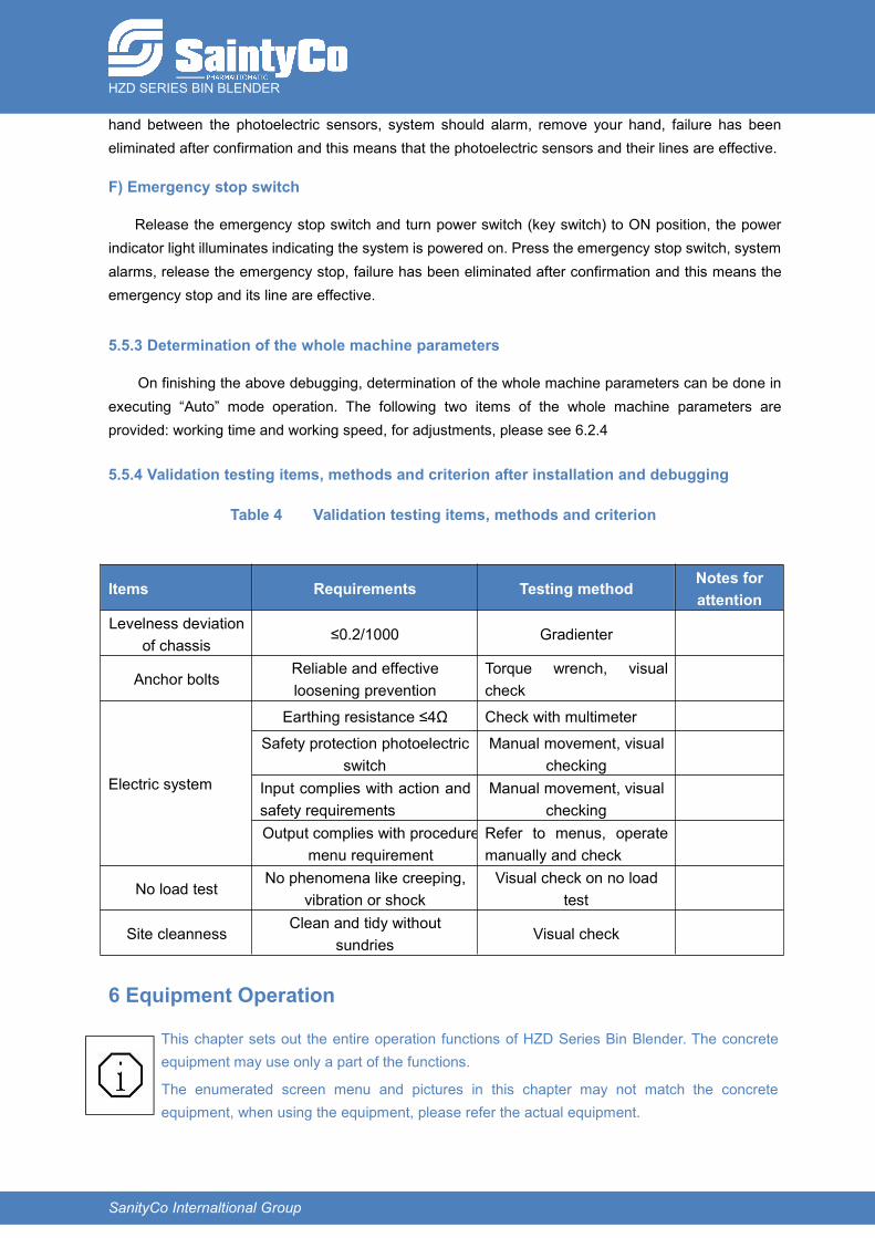
5.5.4 Validation testing items, methods and criterion after installation and debugging
Table 4 Validation testing items, methods and criterion
Items Requirements Testing method Notes forattention
Levelness deviationof chassis
≤0.2/1000 Gradienter
Anchor boltsReliable and effectiveloosening prevention
Torque wrench, visualcheck
Electric system
Earthing resistance ≤4Ω Check with multimeter
Safety protection photoelectricswitch
Manual movement, visualchecking
Input complies with action andsafety requirements
Manual movement, visualchecking
Output complies with proceduremenu requirement
Refer to menus, operatemanually and check
No load testNo phenomena like creeping,
vibration or shockVisual check on no load
test
Site cleannessClean and tidy without
sundriesVisual check
6 Equipment Operation
This chapter sets out the entire operation functions of HZD Series Bin Blender. The concreteequipment may use only a part of the functions.
The enumerated screen menu and pictures in this chapter may not match the concreteequipment, when using the equipment, please refer the actual equipment.
HZD SERIES BIN BLENDER
SanityCo Internaltional Group
In order to keep the equipment’s normal working efficiency and using life, suggest 8 hours pershift to use the equipment.
6.1 Preparations before starting the equipment
a) Every time before starting and operating the equipment, please check the equipment site whethercomplies with the regulations for equipment operation and safety production.
b) Key preparation tasks before installing the bin are:
In the batching process room, charge materials in cleaning acceptance qualified bins only, andaccording to materials density and max load capacity of the equipment.
Confirm the bin lid has been reliably locked and butterfly valve has been closed
Push the materials charged bin into the rotary frame of the blender and align with clampingdevices and bin pads located on the chassis.
c) Operator exits the blending area; put the key switch and turn to “ON” position to switch on the system.After system has been powered on, release the emergency stop switch on the control panel.
d) The strong electric power is connected to the electric control box directly, this is why, for protectingrelative humidity of the environment of the electric control box and for your own safety, please Do notoperate the touch panel with wet hands. Safety protection photoelectric switch and emergency stopare set in order to protect your own and equipment safety, so every time before operating theequipment, please the efficiency of these two equipments; for checking methods, please refer to 5.5.2Debugging of the electric system.
6.2 Equipment start up and Operation procedures and methodsOn finishing checking and preparation tasks before starting, the equipment can be started and blendingoperation can be executed.
6.2.1 Starting the machine
Release the emergency top switch, turn the power switch to “ON” position and then the touch
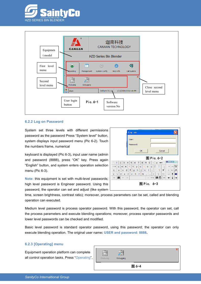
panel displays the starting up menu (Pic 6-1), this means starting up is successful and power supply isconnected to the system. Boot screen display system, the software version number, at all levels of themenu bar and other information.
HZD SERIES BIN BLENDER
SanityCo Internaltional Group
6.2.2 Log on Password
System set three levels with different permissionspassword as the password Press “System level” button,system displays input password menu (Pic 6-2). Touchthe numbers frame, numerical
keyboard is displayed (Pic 6-3), input user name (admin)and password (8888), press “OK” key. Press again“English” button, and system enters operation selectionmenu (Pic 6-3).
Note: this equipment is set with multi-level passwords;high level password is Engineer password. Using thispassword, the operator can set and adjust (like systemtime, screen brightness, contrast ratio); moreover, process parameters can be set, called and blendingoperation can executed.
Medium level password is process operator password. With this password, the operator can set, callthe process parameters and execute blending operations; moreover, process operator passwords andlower level passwords can be checked and modified.
Basic level password is standard operator password, using this password; the operator can onlyexecute blending operation. The original user name: USER and password: 8888.
6.2.3 [Operating] menu
Equipment operation platform can completeall control operation tasks. Press “Operating”,
图 Pic.6-2
图 Pic. 6-3
图 6-4
User loginbutton
Equipmen
t model
First levelmenu
Secondlevel menu
Close secondlevel menu
Softwareversion No
Pic.6-1
HZD SERIES BIN BLENDER
SanityCo Internaltional Group
the second level menu will display “Producing” and “Debugging” as Pic.6-4.
"Producing" can carry out automatic / manual / material turning operation, equipment running statusmonitoring operation, need operator privileges to login.
"Debugging" can be carried out maintenance and overhaul of equipment operation, equipment runningstatus monitoring task, need repair technician privileges to login. Under the menu," production" and"debugging" cannot open. If one operation is activated, another operation item will be disabled, gray:
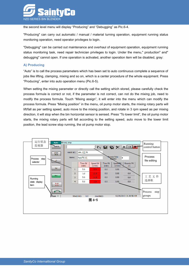
A) Producing
“Auto” is to call the process parameters which has been set to auto continuous complete a sequence ofjobs like lifting, clamping, mixing and so on, which is a center procedure of the whole equipment. Press“Producing”, enter into auto operation menu (Pic.6-5).
When setting the mixing parameter or directly call the setting which stored, please carefully check theprocess formula is correct or not, if the parameter is not correct, can not do the mixing job, need tomodify the process formula. Touch “Mixing assign”, it will enter into the menu which can modify theprocess formula. Press “Mixing position” in the menu, oil pump motor starts, the mixing rotary parts willlift/fall as per setting speed, auto move to the mixing position, and rotate in 3 rpm speed as per mixingdirection, it will stop when the bin horizontal sensor is sensed. Press “To lower limit”, the oil pump motorstarts, the mixing rotary parts will fall according to the setting speed, auto move to the lower limitposition, the lead screw stop running, the oil pump motor stop.
图 6-5
Runningstate displayitem
运行状态
监视器
Process stepselector工 艺 步选择器
Runningcontrol button
Process stepgroups工艺步骤
组态区
工 艺 文 件
选择框
Processfile editing
HZD SERIES BIN BLENDER
SanityCo Internaltional Group
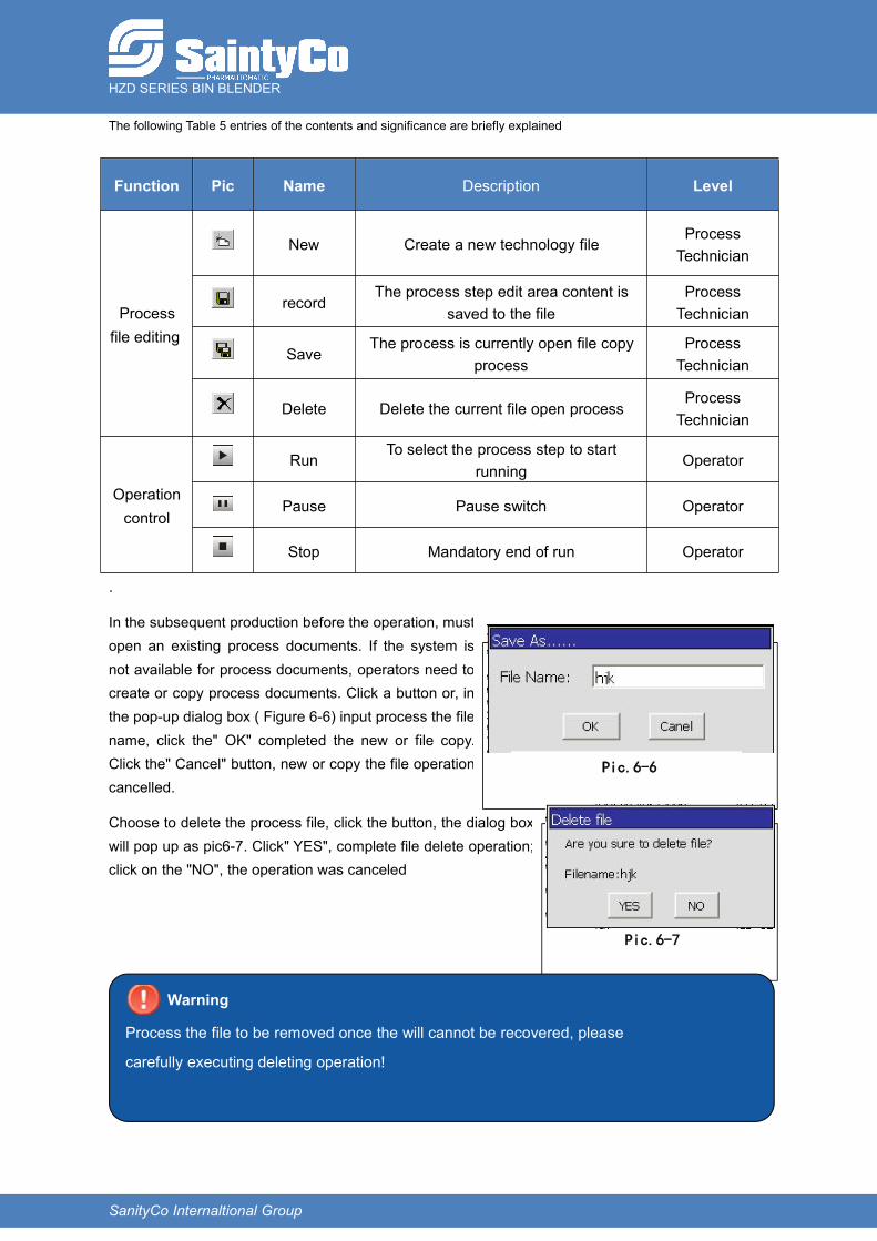
The following Table 5 entries of the contents and significance are briefly explained
Function Pic Name Description Level
Processfile editing
New Create a new technology fileProcessTechnician
recordThe process step edit area content is
saved to the fileProcessTechnician
SaveThe process is currently open file copy
processProcessTechnician
Delete Delete the current file open processProcessTechnician
Operationcontrol
RunTo select the process step to start
runningOperator
Pause Pause switch Operator
Stop Mandatory end of run Operator
.
In the subsequent production before the operation, mustopen an existing process documents. If the system isnot available for process documents, operators need tocreate or copy process documents. Click a button or, inthe pop-up dialog box ( Figure 6-6) input process the filename, click the" OK" completed the new or file copy.Click the" Cancel" button, new or copy the file operationcancelled.
Choose to delete the process file, click the button, the dialog boxwill pop up as pic6-7. Click" YES", complete file delete operation;click on the "NO", the operation was canceled
Warning
Process the file to be removed once the will cannot be recovered, please
carefully executing deleting operation!
Pic.6-6
Pic.6-7
HZD SERIES BIN BLENDER
SanityCo Internaltional Group
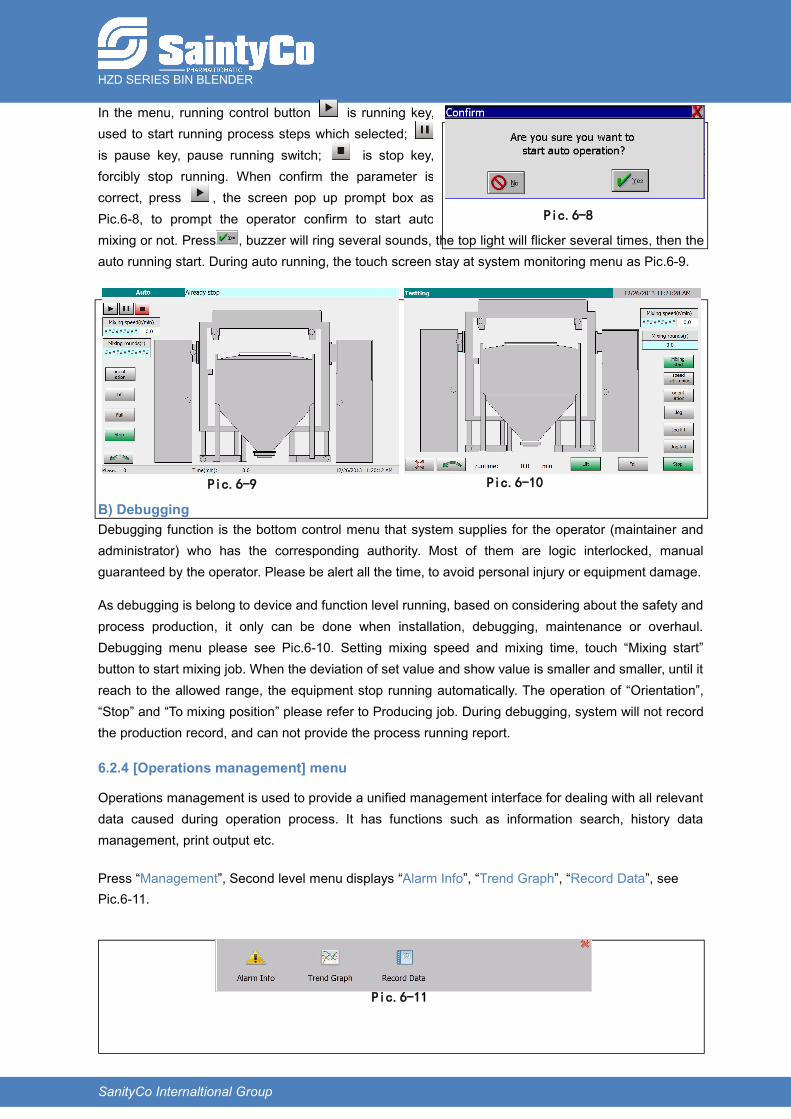
In the menu, running control button is running key,used to start running process steps which selected;is pause key, pause running switch; is stop key,forcibly stop running. When confirm the parameter iscorrect, press , the screen pop up prompt box asPic.6-8, to prompt the operator confirm to start automixing or not. Press , buzzer will ring several sounds, the top light will flicker several times, then theauto running start. During auto running, the touch screen stay at system monitoring menu as Pic.6-9.
B) DebuggingDebugging function is the bottom control menu that system supplies for the operator (maintainer andadministrator) who has the corresponding authority. Most of them are logic interlocked, manualguaranteed by the operator. Please be alert all the time, to avoid personal injury or equipment damage.
As debugging is belong to device and function level running, based on considering about the safety andprocess production, it only can be done when installation, debugging, maintenance or overhaul.Debugging menu please see Pic.6-10. Setting mixing speed and mixing time, touch “Mixing start”button to start mixing job. When the deviation of set value and show value is smaller and smaller, until itreach to the allowed range, the equipment stop running automatically. The operation of “Orientation”,“Stop” and “To mixing position” please refer to Producing job. During debugging, system will not recordthe production record, and can not provide the process running report.
6.2.4 [Operations management] menu
Operations management is used to provide a unified management interface for dealing with all relevantdata caused during operation process. It has functions such as information search, history datamanagement, print output etc.
Press “Management”, Second level menu displays “Alarm Info”, “Trend Graph”, “Record Data”, seePic.6-11.
Pic.6-8
Pic.6-9 Pic.6-10
Pic.6-11
HZD SERIES BIN BLENDER
SanityCo Internaltional Group
“Alarm Info” is summary listing of all history alarm and current alarm which is not eliminated. It can belogged in with operator authority.
“Trend Graph” is the history trend curve for all important variables. It can be logged in with operatorauthority.
“Record Data” is used to manage all history production data, can skim and print. It can be logged in withoperator authority.
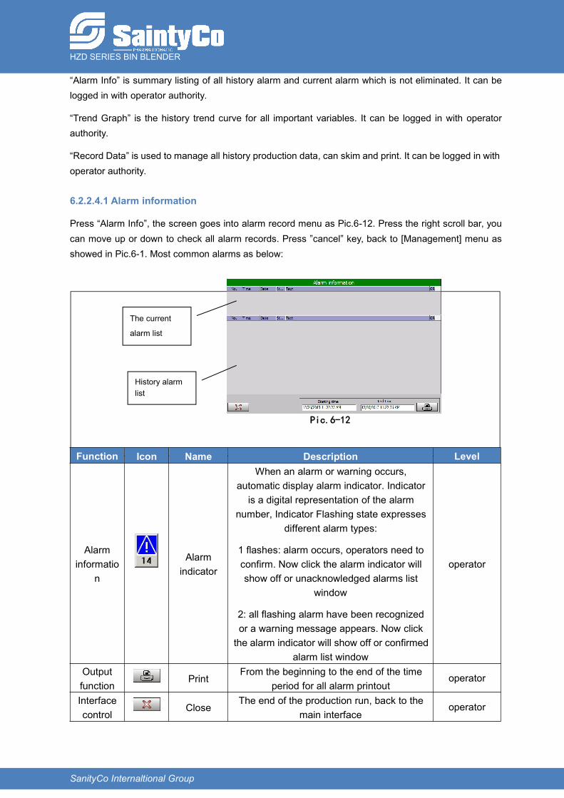
6.2.2.4.1 Alarm information
Press “Alarm Info”, the screen goes into alarm record menu as Pic.6-12. Press the right scroll bar, youcan move up or down to check all alarm records. Press ”cancel” key, back to [Management] menu asshowed in Pic.6-1. Most common alarms as below:
Function Icon Name Description Level
Alarminformatio
n
Alarmindicator
When an alarm or warning occurs,automatic display alarm indicator. Indicatoris a digital representation of the alarm
number, Indicator Flashing state expressesdifferent alarm types:
1 flashes: alarm occurs, operators need toconfirm. Now click the alarm indicator willshow off or unacknowledged alarms list
window
2: all flashing alarm have been recognizedor a warning message appears. Now clickthe alarm indicator will show off or confirmed
alarm list window
operator
Outputfunction
PrintFrom the beginning to the end of the time
period for all alarm printoutoperator
Interfacecontrol
CloseThe end of the production run, back to the
main interfaceoperator
Pic.6-12
History alarmlist
The current
alarm list
HZD SERIES BIN BLENDER
SanityCo Internaltional Group
Alarm sound and light indicator status
Type of alarm Alarm lamp Buzzer
Alarminformation
Twinkle Flash buzzer
Warningmessage
ON Mute
Promptinformation
OFF Intermittent flash buzzer
Confirmed all of the information, the buzzer will mute.
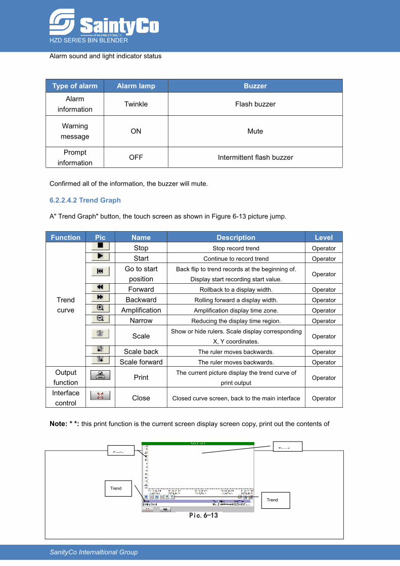
6.2.2.4.2 Trend Graph
A" Trend Graph" button, the touch screen as shown in Figure 6-13 picture jump.
Function Pic Name Description Level
Trendcurve
Stop Stop record trend Operator
Start Continue to record trend Operator
Go to startposition
Back flip to trend records at the beginning of.Display start recording start value.
Operator
Forward Rollback to a display width. Operator
Backward Rolling forward a display width. Operator
Amplification Amplification display time zone. Operator
Narrow Reducing the display time region. Operator
ScaleShow or hide rulers. Scale display corresponding
X, Y coordinates.Operator
Scale back The ruler moves backwards. Operator
Scale forward The ruler moves backwards. Operator
Outputfunction
PrintThe current picture display the trend curve of
print outputOperator
Interfacecontrol
Close Closed curve screen, back to the main interface Operator
Note: * *: this print function is the current screen display screen copy, print out the contents of
Pic.6-13
Trend
variable
table
Scale
Trend
chart
navigatio
n
buttons
Trend
curve
HZD SERIES BIN BLENDER
SanityCo Internaltional Group
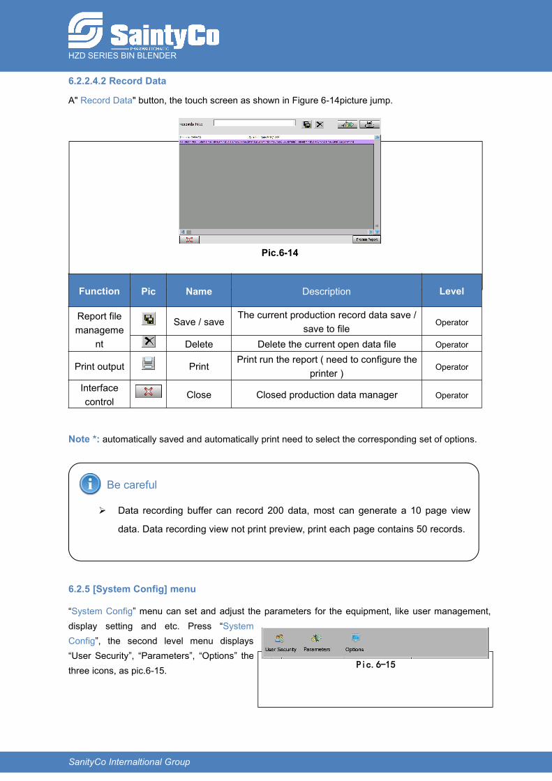
6.2.2.4.2 Record Data
A" Record Data" button, the touch screen as shown in Figure 6-14picture jump.
Function Pic Name Description Level
Report filemanageme
nt
Save / saveThe current production record data save /
save to fileOperator
Delete Delete the current open data file Operator
Print output PrintPrint run the report ( need to configure the
printer )Operator
Interfacecontrol
Close Closed production data manager Operator
Note *: automatically saved and automatically print need to select the corresponding set of options.
Be careful
Data recording buffer can record 200 data, most can generate a 10 page view
data. Data recording view not print preview, print each page contains 50 records.
6.2.5 [System Config] menu
“System Config” menu can set and adjust the parameters for the equipment, like user management,display setting and etc. Press “SystemConfig”, the second level menu displays“User Security”, “Parameters”, “Options” thethree icons, as pic.6-15. Pic.6-15
Pic.6-14
HZD SERIES BIN BLENDER
SanityCo Internaltional Group
"User security" refers to setting the permissions associated with the user login and passwordparameters, according to the user under different group permissions can be set, with correspondingchanges in the project: a member of the administrators group can modify their own password; and amember of the administrators group users can execute changes, modify user group permissions,modified login password operation.
"Parameters" means sets needed for the production process, control and machine parameters.Requires administrator privileges.
"Options" means into the system control panel, can be set to HMI equipment and related parameters,such as a printer, date and time, the displacement of the button correction system parameters. Youneed administrator privileges.
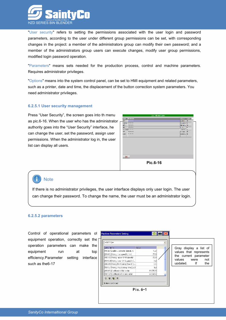
6.2.5.1 User security management
Press “User Security”, the screen goes into th menuas pic.6-16. When the user who has the administratorauthority goes into the “User Security” interface, hecan change the user, set the password, assign userpermissions. When the administrator log in, the userlist can display all users.
Note
If there is no administrator privileges, the user interface displays only user login. The user
can change their password. To change the name, the user must be an administrator login.
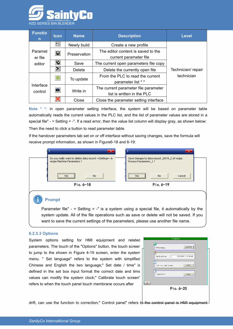
6.2.5.2 parameters
Control of operational parameters ofequipment operation, correctly set theoperation parameters can make theequipment run at topefficiency.Parameter setting interfacesuch as the6-17
Pic.6-16
Pic.6-1
Gray display a list ofvalues that representsthe current parametervalues were notupdated. If theparameter file is" - =Setting = -" said read alist of parameter values.
HZD SERIES BIN BLENDER
SanityCo Internaltional Group
Function Icon Name Description Level
Parameter fileeditor
Newly build Create a new profile
Technician/ repairtechnician
PreservationThe editor content is saved to the
current parameter fileSave The current open parameters file copyDelete Delete the currently open file
Interfacecontrol
To updateFrom the PLC to read the current
parameter list * *
Write inThe current parameter file parameter
list is written in the PLCClose Close the parameter setting interface
Note * *: in open parameter setting interface, the system will be based on parameter tableautomatically reads the current values in the PLC list, and the list of parameter values are stored in aspecial file" - = Setting = -". If a read error, then the value list column will display gray, as shown below:
Then the need to click a button to read parameter table.
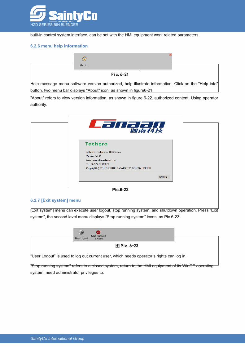
If the handover parameters tab set on or off interface without saving changes, save the formula willreceive prompt information, as shown in Figure6-18 and 6-19:
Prompt
Parameter file" - = Setting = -" is a system using a special file, it automatically by thesystem update. All of the file operations such as save or delete will not be saved. If youwant to save the current settings of the parameters, please use another file name.
6.2.5.3 OptionsSystem options setting for HMI equipment and relatedparameters. The touch of the "Options" button, the touch screento jump to the shown in Figure 4-19 screen, enter the systemmenu. " Set language" refers to the system with simplifiedChinese and English the two language;" Set date / time" isdefined in the set box input format the correct date and timevalues can modify the system clock;" Calibrate touch screen"refers to when the touch panel touch membrane occurs after
drift, can use the function to correction;" Control panel" refers to the control panel is HMI equipment
Pic.6-18 Pic.6-19
Pic.6-20
HZD SERIES BIN BLENDER
SanityCo Internaltional Group
built-in control system interface, can be set with the HMI equipment work related parameters.
6.2.6 menu help information
Help message menu software version authorized, help illustrate information. Click on the "Help info"button, two menu bar displays "About" icon, as shown in figure6-21.
"About" refers to view version information, as shown in figure 6-22. authorized content. Using operatorauthority.
6.2.7 [Exit system] menu
[Exit system] menu can execute user logout, stop running system, and shutdown operation. Press “Exitsystem”, the second level menu displays “Stop running system” icons, as Pic.6-23
“User Logout” is used to log out current user, which needs operator’s rights can log in.
"Stop running system" refers to a closed system, return to the HMI equipment of its WinCE operatingsystem, need administrator privileges to.
图 Pic.6-23
Pic.6-21
Pic.6-22

HZD SERIES BIN BLENDER
SanityCo Internaltional Group
7 Trouble shooting and analysisMalfunction will be showed on the operation screen automatically for convenient solution. Duringrunning, the malfunction will stop the system immediately, system buzzer hoot with alarm glitter toremind the operator to solve in time. The information of common fault will be displayed on the touchscreen.
7.1 Failure of the control system
7.1.1 Failure of Auto positioning
After mixing finished, if the bin rotates with low speed can not be positioned after eighty seconds, it canbe as auto positioning failure.
Reasons for positioning failures are: ①position of the positioning sensors have changed or failure ofthe sensors, so adjustment of the installation position shall be done or change the sensors; ②brakingfailure of the rotary motor so a correct braking cannot be achieved, in this case the motor braking shallbe serviced or change the brake.
Notify maintenance personnel. System returns to Pic 6-4 operation option menu.
7.1.2 Rotary body is not on horizontal position
When the rotary body is not on horizontal position, the bin cannot be fallen to the ground or theblending cannot be operated.
Reasons analysis and troubleshooting: ①rotary frame was not positioned last time, manual positioningshall be executed; ②position of sensor for checking the horizontal level has changed or failure of thesensor, adjustment or change of the sensor shall be executed; ③braking failure of the rotary motor so acorrect braking cannot be achieved, in this case the motor braking shall be serviced or change thebrake.
After the trouble shooting, screen returns to Pic 6-4 functions selection menu automatically.
7.1.3 Bin is not installed in position
Reasons analysis and troubleshooting: ① Misoperation, executing the blending operation without anybin. The following tasks shall be done: a/ reinstall the bin and make sure it is well installed; b/ train theoperator. ② The bin is install in position but there’s a failure of the sensors (photoelectric sensors),sensors shall be serviced or changed.
After trouble shooting, screen returns to operation option menu Pic 6-4.
7.1.4 Failure of the lifting transmission
When there is an alarm like “lifting transmission fault” appears, please inform the maintenancepersonnel to deal with. Maintenance personnel check if the clamping and landing signal is normal ornot.

HZD SERIES BIN BLENDER
SanityCo Internaltional Group
After the trouble shooting, screen returns to Pic 6-4 functions selection menu automatically.
7.1.5 Loss of bin signal during the blending operation
Reasons analysis and troubleshooting: ① PLC cannot detect clamping signal, check whether theclamping switch is working correctly and move 1~2mm the limit switch for clamping in position to thecone bar.
After the trouble shooting, screen returns to Pic 6-4 functions selection menu automatically.
7.1.6 Lifting motor is overloaded
Reasons analysis: the over current protection relay has operated so the equipment stoppedoperating. Trouble shooting: ① check whether Power supply has phase lack and eliminate the failure;② check whether setting of the protective relay is correct, if not reset it; ③ check whether thecontactor is connected correctly, if not restore the contactor; ④ check and read the manual of themotor, eliminate motor failure.
After the trouble shooting, screen returns to Pic 6-4 functions selection menu automatically.
7.1.7 Conflict of upper and lower limit signals
When the bin’s already in lower limit position, if the bin is lifted to the upper limit position and theclamping signal still subsists; or the bin is lifted to the upper limit position and the lower limit position stillsubsists, so the system will alarm to remind the operator the reason of the failure.
After the trouble shooting, screen returns to Pic 6-4 functions selection menu automatically.
7.2 Failure of the mechanical transmission system
Table 5 Failures of the mechanical transmission system and trouble shooting
No. Failures Reasons Trouble shooting
1On blending
operation, bin hasslipping phenomena
Low clamping pressure
Adjust the installation positions of limitswitches
Set higher the protective torque of thetorque limiter
2High noise of
reducer
On installation, shaftcenter line is not aligned
Re-adjust the two sides anchor bolts
Abrasion of the reducer Service or change the reducer
3
Motor is workingcorrectly but thelifting mechanismdoesn’t operate
Failure of the coupling
Abrasion of the liftingscrew-nut pairs
Change or service and apply lubricant
4Incorrect horizontalpositioning of the
Positioning device hasloosened
Re-adjust and fasten the screw
HZD SERIES BIN BLENDER
SanityCo Internaltional Group
rotary body
5Failure of reaction ofthe security line
switch
Photoelectric switch hasfailure or dustaccumulation
Clean dust or sundries
Check the lines
Check whether the installation of thephotoelectric switch is correct
Change the photoelectric switch
6Bin has been loadedbut “Install the bin” is
still displayed
Photoelectric switch hasfailure or dustaccumulation
Clean dust or sundries
Check the lines
Check whether the installation of thephotoelectric switch is correct
Change the photoelectric switch
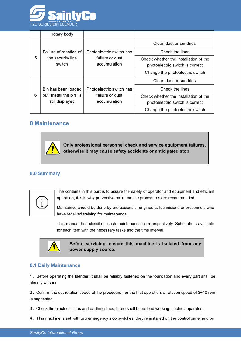
8 Maintenance
8.0 Summary
The contents in this part is to assure the safety of operator and equipment and efficientoperation, this is why preventive maintenance procedures are recommended.
Maintaince should be done by professionals, engineers, techniciens or presonnels whohave received training for maintenance.
This manual has classified each maintenance item respectively. Schedule is availablefor each item with the necessary tasks and the time interval.
8.1 Daily Maintenance
1、Before operating the blender, it shall be reliably fastened on the foundation and every part shall becleanly washed.
2、Confirm the set rotation speed of the procedure, for the first operation, a rotation speed of 3~10 rpmis suggested.
3、Check the electrical lines and earthing lines, there shall be no bad working electric apparatus.
4、This machine is set with two emergency stop switches; they’re installed on the control panel and on
Only professional personnel check and service equipment failures,otherwise it may cause safety accidents or anticipated stop.
Before servicing, ensure this machine is isolated from anypower supply source.
HZD SERIES BIN BLENDER
SanityCo Internaltional Group
the main machine respectively. Before operating, they shall be released to start the system.
5、 This machine has a large rotation diameter; before starting the system, operator shall exit theblending area.
6、When loading and dismantling the bin, please operate lightly to not damage the surfaces of bin andmachine frame.
7、Check the fastened parts of the rotary body have not loosened periodically; if yes, fasten them.
8、Checking of the safety loop
1) Periodic checking; test the reliability of the safety loop operation
2) Checking items are the following:
a: Reliable operation of the emergency stop switch
b: Reliable operation of the emergency stop relay
c: Reliable operation of the security line switch
d: Reliable operations of the alarm light and buzzer
3) After long machine shut down, before starting the machine again, maintenance personnel mustcheck the safety of the machine.
9、Maintenance of sensors
1)、Proximity switch:
Check the installation position including clearance between the device and the stop block
At any moment, clean the switch and around the stop block
2)、Photoelectric switch:
At any moment clean around the switch and ensure its light transmittance.
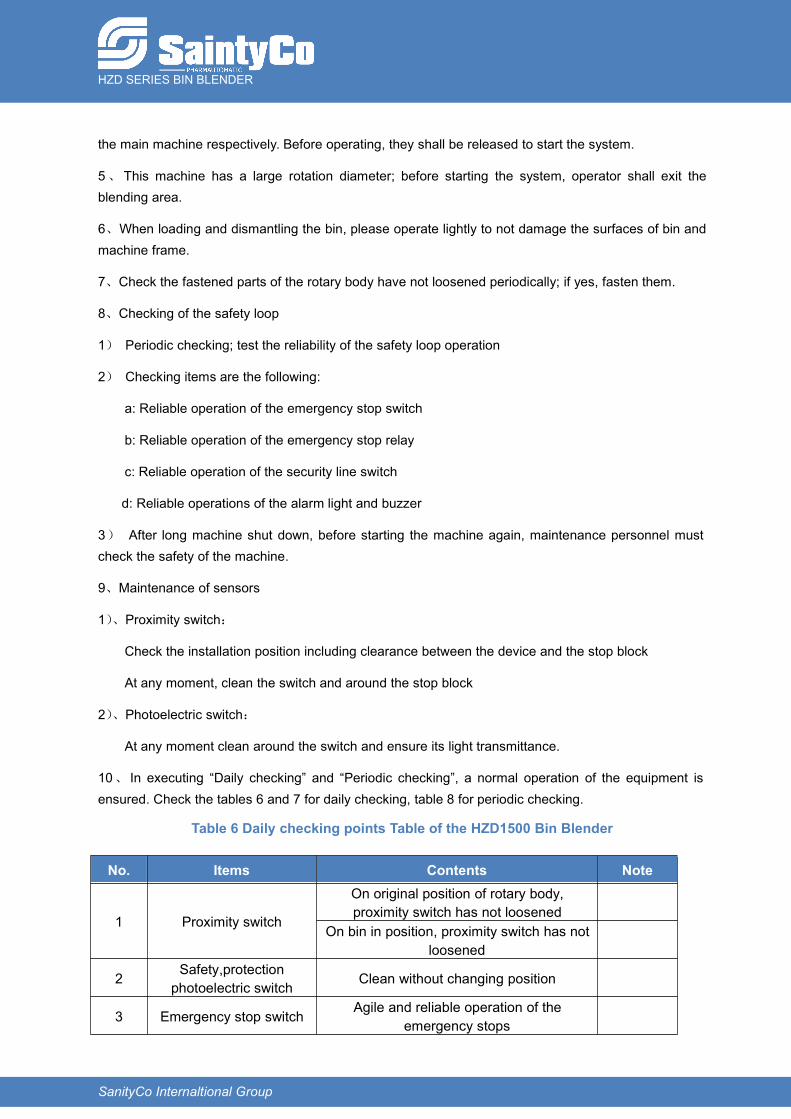
10、 In executing “Daily checking” and “Periodic checking”, a normal operation of the equipment isensured. Check the tables 6 and 7 for daily checking, table 8 for periodic checking.
Table 6 Daily checking points Table of the HZD1500 Bin Blender
No. Items Contents Note
1 Proximity switch
On original position of rotary body,proximity switch has not loosened
On bin in position, proximity switch has notloosened
2 Safety,protectionphotoelectric switch Clean without changing position
3 Emergency stop switch Agile and reliable operation of theemergency stops
HZD SERIES BIN BLENDER
SanityCo Internaltional Group
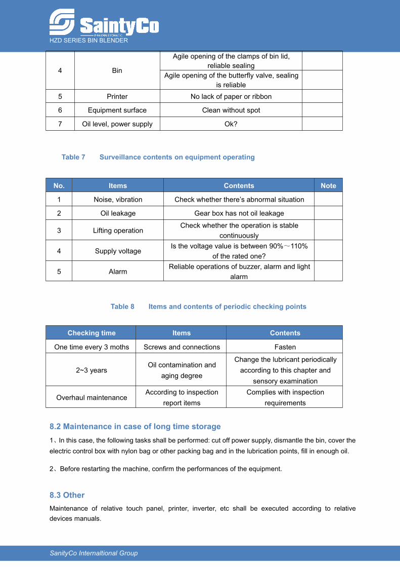
4 Bin
Agile opening of the clamps of bin lid,reliable sealing
Agile opening of the butterfly valve, sealingis reliable
5 Printer No lack of paper or ribbon
6 Equipment surface Clean without spot
7 Oil level, power supply Ok?
Table 7 Surveillance contents on equipment operating
No. Items Contents Note
1 Noise, vibration Check whether there’s abnormal situation
2 Oil leakage Gear box has not oil leakage
3 Lifting operationCheck whether the operation is stable
continuously
4 Supply voltageIs the voltage value is between 90%~110%
of the rated one?
5 AlarmReliable operations of buzzer, alarm and light
alarm
Table 8 Items and contents of periodic checking points
Checking time Items Contents
One time every 3 moths Screws and connections Fasten
2~3 yearsOil contamination and
aging degree
Change the lubricant periodicallyaccording to this chapter and
sensory examination
Overhaul maintenanceAccording to inspection
report itemsComplies with inspection
requirements
8.2 Maintenance in case of long time storage1、In this case, the following tasks shall be performed: cut off power supply, dismantle the bin, cover theelectric control box with nylon bag or other packing bag and in the lubrication points, fill in enough oil.
2、Before restarting the machine, confirm the performances of the equipment.
8.3 OtherMaintenance of relative touch panel, printer, inverter, etc shall be executed according to relativedevices manuals.

HZD SERIES BIN BLENDER
SanityCo Internaltional Group
9 LubricationTable 9 Items and contents of periodic checking points
Lubri.points Position name Lubricant Lubrication
period Note
1 Guide pillar High-quality lubrication grease 14 Days 4 points
2 Supporting bearing High-quality lubrication grease Overhaul time
3 Left screw-nut pair High-quality lubrication grease 14 Days
4 Left gear pair High-quality lubrication grease 90 Days
5 Gearbox According to gearboxrequirements 1500 Hours First time at
1000 hours
6 Motor bearing According to motorrequirements Overhaul time
7 Right gear pair High-quality lubrication grease 90 Days
8 Right screw-nut pair High-quality lubrication grease 14 Days
9 Blending gearbox According to gearboxrequirements 1500 Hours First time at
1000 hours
10 Bearing of blendingmotor
According to motorrequirements Overhaul time
Please see Pic 9-1 for the different lubrication parts.
Pic.9-1
HZD SERIES BIN BLENDER
SanityCo Internaltional Group
10 Transportation and storage
10.1 Package
After FAT, the equipment is separated into parts as frames, motor, etc and packed into wooden boxes.Do not invert or side put the boxes, all parts have been labeled.
10.2 Transportation
This equipment suits for shipments by land and sea. The blender is separately packed according to itsparts; when handling them, do not bump or damage them.
Handle with forklift truck on land transportation. During the handling, make sure to not damage thepacking boxes. For the transportation, use firm and solid hemp rope to fasten the boxes and abide bythe following points:
1)Do not invert or side put the boxes or too inclined.
2)When hoisting or lowering the boxes, they shall be handled on the correct direction, do not inclinethem or bump. Do not hoist and lower them too quickly.
When transported by sea, abide by the relative regulations for sea transportation.
10.3 Storage
Store in a dry, ventilated and without corrosive medium room.
11 Unpacking and Checking
11.1 Unpacking attentions
1、Installation service personnel from manufacturer or its agent should be present at the unpacking site.
2、Before unpacking, check if the package、quantity、product name and model are conform to thepacking list.
3、Dismantle first the top lid of package case, and then open four sides to take out the equipment.
11.2 Items Checking
1、Documents with machines (include: packing list、qualification certificates、operation manual、inspection report、attachments list, etc.)
2、Check the items according to the packing list and record it. Check if the appearance of the machinehas distortions and scratches caused by bumping, knocking and severe vibrations.