
HYDRONAUTICS,. incorporated, research in · PDF fileHYDRONAUTICS,. incorporated, research in...
90
17 rM4, \SEP 0 198 HYDRONAUTICS,. incorporated, research in hydrodynamics foru (ka)IIHI k1olk. i t .m '~4 WNu agm. 0 C.. mie ftMei Shoo Read Newud Ceut, LUel, VA dtatributIon itl i tliinted. $2 09 08 02
Transcript of HYDRONAUTICS,. incorporated, research in · PDF fileHYDRONAUTICS,. incorporated, research in...

17
rM4,
\SEP 0 198
HYDRONAUTICS,. incorporated,research in hydrodynamics
foru (ka)IIHI k1olk. i t .m '~4 WNu agm. 0 C.. mie ftMei Shoo Read Newud Ceut, LUel, VAdtatributIon itl i tliinted.
$2 09 08 02

HYDRONAUTICS, Incorporated
TECHNICAL REPORT8268-1
SELF RESONATING PULSED WATER JETSFOR AIRCRAFT COATING REMOVAL:
FEASIBILITY STUDYby
Georges L. ChahineVirgil E, Johnson, Jr.
andGary S. Frederick
June 1982
The information in this report is based upon work supported by
The Department of DefenseDefense Small Business Advanced Technology Program
Office of Naval ResearchArlington, VA 22217
Under
Contract No: N00014-82'-C-0143
S3EPO Q8 19
ttcwa (1~ *W 0I pul'I.-~o is u 4,

C I.HYDRONAUTICS, IncorporatedI " -----
," .. , J'¼... C
- - (I KJ/o , , ' "I I
TABLE OF CONTENTS
Page iNo.
I. INTRODUCTION ...... *, .. .. . ....
A.. Objective . .. ... . . . . . • . .. . . 1B . Background . . . . . . . ... . . . . . .. . . 2
SII. SERVOJETCOCPS . .. . .. .. ........................
A. Background . , , , , , F , , .. ..B. Pulser SERVOJET *................................ ,.... 7C. Pulser-Fed SERVOJET .. . .. ... . . 9D. Organ-Pipe SERVOJET .......................... , . 10
SIII. OPTIMUM OSCILLATIONS FREQUENCY RANGE . , , . ,.... 12
A. Stresses Due to a Point Load on an Infinite* ~~Elastic Medium..,,.................... 12
B. Impact Forces ... . . . ....... 13C. Relations for Complete Funching in a"
Mlodulated Jet ,. . . . . *... . . ..... * 14D. Optimum Frequency .... ........ ..*-"E. Comparison with Existing Studies..........18
* 1 IV. EXPERIM~ENTAL FACILITIES AND TECHNY.QUE3 USED . .... 19
SA. Faci,.ities....... . . ..................... 19"* B. Techniques for Bunching Detection . , * . . •. 21
C. Tested Nozzles........................... 22
V. EXPERIMENTAL RESULTS. . ...................... .. .26A. Flow Corrections............,.................. 26B. Photographic Evidence................27C. Pressure Fluctuation and Laser Beam Interruption , 291). Acoustical Study of the Various Jets . .,. ... 33E. Paint Removal Tests ... . .. *.. .3
,'VI, CONCLUSIONS , . , , , , ,. , , . , , . , . ,. , , 41
.;tREFERE•NCES .. ............. ,...... 44
"•:: FIGURES
•:! ' TABLES
j '~ -'-"... .--
PL 01

HYDRONAUTICS, Incorporated
•. -ii-
FOREWORD
This report was prepared by HYDRONAUTICS, Incorporated,
F Laurel, Maryland under ONR Contract No. N00014-82-C-0143. The
Scientific Officer for this contract was Mr. David Siegel,
Code ONR 260. The authors wish to acknowledge the valuable
discussions and suggestions provided by Mr. Siegel during this
program.
We also want to thank Mr. Gary Gates, Code 61225, Naval
Island Naval Air Station, for providing all of the test panels
used during this effort, and for his important guidance in the
real-life aspects of aircraft cleaning. The assistance and
counsel provided by Dr. Andrew F. Conn and Mr. George E.
Matusky, HYDRONAUTICS, is gratefully acknowledged.
PATENTS
The principles of passive jet excitation described in this
report were included in U. S. Patent Application Serial Number
215,829, by V. E. Johnson, Jr., HYDRONAUTICS, Incorporated
dated December 12, 1980, and subsequent U. S. continuations and
Foreign Applications.
,}'I

HYDRONAUTICS, Incorporated.
S~-iii-
S~SUMMARY
This study examined an innovative technique to augment theefficiency of water jets and the degree of their control in re-
moving aircraft coatings and preparing surfaces for recoating.It dealt specifically with a' a2sive disruption of a waterjetinto slugs in order to produce high-frequency, high-pressureshock wave impacts, The approach was to use self-resonatingchambers, which amplified and structured the turbulent shearlayer of the jet. The acoustical oscillations produced were tunedto the predominant natural frequencies of the nonexcited jet,The main objective of this phase of the research program, whichwas to establish if self-resonating nozzles are able to produce,at a relatively large standoff distance, a train of slugs capableor removing aircraft coatings at a high and controllable rate,
was successfully achieved,
To meet this objective, two types of resonating nozzleswere built and tested against various types of coatings definedafter consultation with the U.S. Navy. The results were comparedwith a conventional nozzle. A more fundamental, parallel approachwas followed in order to correlate the resonance characteristics
with the impact forces imparted on the eroded surface.
The experimental study shows that the bunching characteristicsof the jet correspond to the acoustical measurements of pressureoscillations in the nozzle tube, The frequency spectrum of theseoscillations perfectly correlated with that of the pressure fluc-tuations on a transducer target. A new technique consisting ofmeasuring the oscillations of the interrupted light of a laserbeam onto a photo multiplier has also shown a perfect correlationwith the preceding spectra, The oscillation frequencies as well as
* , the bunching characteristics (wave length, optimum standoff dis-
tances) are correctly predicted with a preliminary analysis,
___ ___ __.. .. __ . I .M9..

HYDRONAUTICS, Incorporated
-iv-
Paint cleaning tests were performed both on carbon-fiber re-
inforced composites and aluminum panels. The composite panel testswere not significant due to large discrepencies in the paint andmaterial.properties. Very positive results were ob.;'ained withthe aluminum panels which showed great improvement relative toa standard jet at high standoff distances. We are confidentthat well optimized self-resonating pulsed jets 'can overcome thedrawbacks of existing water jet methods, and provide a practicalreplacement or primary supplement for chemical removal methods,
/' II-. . . . . .. . . . ..-

HYDRONAUTICS, Incorporated
-1-
I. INTRODUCTION
A. Ob ective
The objective of this project was to investigate the feasi-bility of disrupting a high pressure water jet into a discrete
train of well organized slugs through passive acoustic self-ex-citation of the jet, and as a result to enhance the ability ofthe Jet to remove aircraft coatings and to prepare surfaces for
recoating, This innovative technique takes advantage of thewater hanumer pressures produced by the slugs' impact (which are
much higher than the stagnation pressures generated by a con-
tinuous jet), without the drawbacks of having a mechanical ro.
tating interrupter. In addition this technique provides largerworking standoff distances, wider areas of impact and thusgreater control of the energy imparted to a target than a cavi-
tating jet, It is therefore capable of overcoming the drawbacksof existing water jet methods in preparing aircraft surfacesfor repainting and of pr~oviding a primary supplement if not a
practical replacement for chemical removal metbods.
This first phase of the research concentiatej1~inly on aqualitative assessment of the self-oscillating jets (SERVOJETS),in the development of techniques able to rapidly quantify thebunching characteristics of subsequently designed SERVOJETS,and in a limited quantitative assessment of the cleaning power
of this jet on aluminum and carbon-fiber reinforced aircraftpanels. Another important objective was to determine theexistence of a correlation between the geometrical appearanceof a jet, its acoustical characteristics and the generatedpressures on a target. Such a correlation allows one to con-centrate on the geometrical and acoustical properties of the
jet in any future optimization of the SERVOJET's nozzles,
If1-

HYDRONAUTICS, Incorporated
"-2-
B. Background
Coatings applied te aircraft surfaces for aesthetic reasons
or for protection are periodically removed for repair and re-
coating. Preparation of the surfaces and coating removal is
presently accomplished mainly with chemicals,
The chemical stripping procedures now used are slow, costly,
dangerous to personnel, and environmentally unsafe without sub-
stantial controls. Both theU,S. Navy and Air Force are actively
seeking a replacement for chemical paint strippers and removers.
Various types of mechanical techniques have been examined:
water jets, carbon dioxide pellets, as well as various abrasive-
grit blasts and lasers, All of these methods, however, have the
same drawback -namely, a strong potential for damaging the sub-
strate. Laser blasting is promising, but requires revolutionary
improvements in the state-of-the-art before becoming economi-cally viable.[l],
Laboratory experiments involving the removal of paint from
aluminum and glass fiber reinforced plastic (GFRP) substrates
have demonstrated the basic selectivity of the water jet erosive
process in comparison with the chemical procedures, While chem-
ical stripping attacks indiscriminately both top coat and primer,
we found in earlier tests performed at HYDRONAUTICS, Incorporated
with cavitating jets that the lower "erosion strength" (i.e.,
energy needed to be removed from the panel), S, of the polyu-rethane-based top coat allowed it to be removed with little orno damage to the epoxy-based primer ([l], Table 2). The erosionstrength of this primer was nearly the same as the aluminumpanel, and substantially greater than that of the GFRP. Indeed,as we will underline later in this report, this concept ofrelative "erosion-strength" of various coatings and of the sub-strate is to be emphasized, For exaaiple, in situations where
--
HYDRONAUTICS, Incorporated
-3-
the substrate erosion strength is less than or equal to that ofthe coating, no purely mechanical method can remove 100 percent
of that coating without taking away some of the substrate. For-tunately, however, during standard aircraft overhauls, it isdesirable not to remove an intect and well-bonded primer [2].
The "selectivity" of water jets which we havetobserved, as notedabove,makes water jets more effective in this case than chemicalstrippers for most normal maintenance of Navy or Air Force equip-ment. The iame reasoning suggests that worn top coats and primers
for deteriorated coatings can be easily removed with no damageto the aircraft surfaces. For all such applications, self-rep
sonating pulsed jets would be much more effective than regularjets, as higher impact forces would be imparted on a larger
cleaning surface.
In a study supported by the Air Force [E), it was concluded
that water jets showed the greatest promise among the severalmechanical coating removal techniques which were considered,
As discussed below, self-resonating pulsed jets have intrinsic"advantages in comparison to any other type of water jet -when
attempting to remove coatings from the complex, and readily-damaged surface of an aircraft,
The potential advantages of an interrupted jet compared to
a continuous one are quite well-known and have been of interestr' for jet erosion enhancement for a long time. While the pressureproduced by a continuous jet on a target, is of the same order
of magnitude as the stagnation pressure, k p V2 (where p is theliquid density and V is the jet speed), it is of order pcV (where
"c is the speed of sound in the liquid) after each impact for a
train of slugs. This basic interpretation shows that by pro..
ducing discrete water packets one can take advantage of impact
forces, an order of magnitude higher than in the continuous

HYDRONAUTICS, Incorporated
-4-
case, to initiate and then propagate microcracks in the coating
to be removed. In addition, the produced slugs have a greater
ratio of impact area to water volume which enhances the surfacecleaning effectiveness and introduces, through the standoff dis-tance variable, an additional degree of control of the cleaningrate. More importantly, the cyclical unloading generated witha train of blugs produces absolute tensions which promote frad-
tures and unbonding of the various coating layers from eachother and from the substrate.
At chis time, although an admittedly promising way to utilizewater to cut and clean, pulsed Jets are not operational, due tothe lack of a practical, nonintrusive method for interrupting the
* jet. Devices using a rotating perforated disc have often beenused, and results showing the efficiency of such devices have
* been reported, for instance, by Lichtarowicz, et al, [3],Summers [4], Erdmann-Jesnitzer, et al, [6], and Janakiram, etal. [6]. Discrete water packets have also been obtained by
water cannons [7], achieving very high exit velocities. However,only very low repetition rates are possible, and the practicalityof such devices is limited due to the high stresses developedwithin the nozzle, The most interesting mechanically interruptedor modulated jet is that developed by Nebeker [8]. It has theadvantage of being self-contained and self-driven, However,being based on a mechanical interruption of the jet makes it
present the disadvantages of rapid wear, probably due to cavita-tion erosion in the slots and to friction, and thus to a veryshort lifetime, and noncontrolled frequencies of the modulator.
Obtaining passively, without any moving parts, the modulationof the jet has the great advantage of achieving an appreciableincrease of material removal efficiency, with minimum losses,no wear problems and no need for any additional external source
- .,i--

HYDRONAUTICS, Incorporated
-5-
I of power. In addition, it has the advantage of generating con-
trolled frequencies which are not time dependent 3ince the
system is free of wear problems, As we will see below thesefrequencies are much higher than those used in mechanical
devices and correspond to the desired optimum frequencies for
maximum material removal efficiency of the jet, The possibility1• of extending, if desired, the effective range of the modulated
jet (maximum standoff distance for optimum cutting rate) by air
or water-sheathing adds to the relevance of this innovative
technique.
S.***1

HYDRONAUTICS, Incorporated
-6-
II. SERVOJET CONCEPTS
A. Background
For over 10 years, HYDRONAUTICS, Incorporated has been engaged
in the development of high-speed cavitating jets for numerous
applications including drilling, mining, and cleaning. The
CAVIJET® cavitating fluid jet method is one of the very few
successful attempts to harness, for useful purposes, the de-
structive power of cavitation. One of the recent developments
in our CAVIJET program is passive, self-.resonating devices for
modulating the flow in CAVIJET nozzles. These simple devices
operate most effectively in the frequency range, f, correspond-
ing to a Strouhal number (S - fd/V) between 0.3 and 1.2, and 'have
produced rms amplitudes in some configurations as high as 50
percent of the mean jet flow (d is the jet diameter),
The principle of the basic CAVIJET, which consists of a
submerged jet, is to produce cavitation in the shear zone be-
tween the Jet and the surrounding liquid, The cavitation ob-
served in this zone has the tendency to be moderately structured
in ring vortices with a preferred period [9]. These rings be-
come discrete and the jet very structured when the flow is
excited at the preferred frequency which corresponds to a
Strouhal number of approximately 0.3 [10,11)] This observation
was already known for air-jets [12]; when excited very moder-
ately for the same approximate Strouhal number, the flow becomeshighly structured into a sequence of ring vortices persisting
for several jet diameters downstream of the nozzle exit. Many
investigators [12-16] have examined phenomena related to fluc-
tuating jets, either self resonating or with an external means
for stimulating or driving the pulsations in the jet flow,
Schematics of several, concepts available for pulsing jets are
S............... ......................-------......... .. -.... ..., ... 7,
I
HYDRONAUTICS, Incorporated
-7-
4 shown in Figure 1. The basic principle of the search -or aresonating jet is mainly to find a way of matching its pre-
dominant turbulent frequency with that of the resonator. Forself-resonance the resonator has to be nonintrusive. An organ-pipe resonant chamber or a Helmholtz resonant oscillator (Figure2) are among the several rather simple devices already testedsuccessfully at HYDRONAUTICS for underwater cavitating jets.
The SERVOJETS studied in this project are the same typesas those already tested in submerged conditions and can be
grouped into three types, They have been given the descriptive
names: "PULSER SERVOJET", "PULSER-FED SERVOJET" and "ORGAN-
PIPE SERVOJET". The concept for each type will now be described.
B. PULSER SERVOJET
The configuration for thiL self-resonating jet concept, a
tandem-orifice Helnholtz resonator, is shown in Figure 2a. Thesteady, high-pressure flow enters through the feed line, diam'-
eter, DF' and passes through an entrance section of length, Land diameter, Dp. The flow then contracts through the firstorifice: di, passes through the chamber (volume; V; length,
L; diameter; dT) and exits through the second orifice, d 2.
If operated at its optimum Strouhal number, Sd, - fdi/Vi,discrete ring vortices will be formed in the jet issuing fromorifice dl. When a vortex arrives at the second orifice, d 2 ,a distance L away from dl, a pressure signal will be trans-mitted upstream, arriving back at d , after a time: tL - L/c,where c is the speed of sound in the fluid, If the length, L,is selected as;
L-NX -. tLVc,()

HYDRONAUTICS, Incorporated
-8-
where: X is the wave length,
N is an integer number of vortices, and
V is the vortex convection velocity, V. -a
then the pressure signal will arrive at d, at exactly the time
required to excite a new vortex, Using the expressions for Sd,
and tL' and introducing the Mach number: M - Vdc, Equation
(1) can be rewritten nondimensionally as;
' L , , N__,/V,,),,,
S= Sd (1 + MVc/v') •(2)
Since 0.75< • Vc/V. < 0,5, and Sd - 0.3n, the chamberlength is determined for M, .,< 1, by;
N <'L < N.31.6 _ 5- 2 .3 (3)
The frequency Of the cylindrical Helmholtz chamber, for
large values of V/dj' is approximately given by the following
equation;
Thus the optimum diameter dT for maximum amplification is
given by the relation;
1 (5)
which becomes after taking into account the inequality (3);
G0.42 '1 < T<P 6 1-w v -(6)
Swhich akinM,
HYDRONAUTICS, Incorporated
-9-
The ratio d 2 /d,, appeared experimentally to give optimum results.at a value of 1.2 [17].
C. PULSER-FED SERVOJET
A self-resonating nozzle concept, which has been shown to
be capable of providing several advantages relative to theI PULSER SERVOJET, is shown in Figure . Shown are a basic design,Figure 3a, and two designs (3b, 3c) with alternative diffusiont+ chambers. In this concept the exit nozzle, d3, is fed a fluc-tuating excitation by the same tandem-orifice with intervening
* . resonant chamber configuration as described in the precedingsection.
The advantages of the PULSER-FED SERVOJET concept havebeen shown to be:
a. The jet formed by the exit nozzle, d3 , has a more uni-
form velocity distribution, and the vortices formed here are
more cleanly defined.
b. The PULSER (di) nozzle can be selected to operate ata Strouhal number higher than that of the exit (d 3 ) nozzle.This implies that the resonant chamber pressure can be higherthan pa' the ambient pressure surrounding the jet exiting fromd3, and that the velocity in the chamber is less than VO.Therefore, the cavitation number in the chamber will be muchhigher than that of the exiting jet, and cavitation in thischamber can be avoided,
tC. The diffusion chamber (Ld, D,) may be designed to en-hance the amplitude of modulation provided by the PULSER chamber.
Disadvantages of the PULSER-FED concept include:
a. A more complex machanical configuration, and
b, The overall energy loss, caused by losses in the

HYDRONAUTICS, Incorporated
-10-
diffusion chamber, is greater than for the PULSER CAVIJET con-
cepts,
The latter problem can be minimized by using the alternativediffusionchambers shown in Figures 3b and 3c. At any ratethese losses are, by far, smaller than the losses in the pre-sence of interrupting devices such as rotating discs or rotors,
d, ORGAN-PIPE'SERVOJET
A SERVOJET concept which offers the simplest design, andwas very successful for cavitating submerged applications isshown in Figure 2b. This concept achieves peak acoustic reso-nance when a standing wave forms in the "organ pipe" section(length; Lp, diameter; D). This section is created by the"upstream contraction, (DF/D) 2 and the nozzle contraction, (D/d) 2 .Peak resonance will occur when the frequency of the organ-pipewave is near the preferred Jet structuring frequency. Theexact resonance frequency is dependent on the contractions ateach end of the organ-pipe, For instance, if both (.D/D) 2 and(D/d) 2 are large, then the first mode resonance in the pipewill occur when the sound wave length in the fluid is approxi-mately four times L When the contraction ratio D/d is nottoo big, resonance occur when the wave length is approximatelytwo times Lp
The real design problem for an ORGAN-PIPE SERVOJET is thegeneration of the initial excitation of the osc£lations inthe organ-pipe chamber, This is successfully achieved in the
submerged mode through a feed-back mechanism on the exit sectionof the nozzle, As discussed below, time has not allowed forsuch success for in-air application and further research isrequired to achieve this objective. Acoustic analysis andexperimentation unde' submerged conditions have led to the
-lI -

t ~ HYDRONArY2ICS, Incorporat-ed
following approximation, useful for estimating the length ofthe organ-pipe:
L ) K n(7 )
where the "mode parameter", K. is given, for DF/D >> 1, by:
-funa. (ni, ) 2n1 for (8
n D 1();'for 21 9
In these express~ions;
n-made number of the organ-pipe,Sd * - crit~ical Strouhial number, fd/V 0.3 x nl
M -Ma~ch -number, V/c.
An empirical relation found useful for designing an ORGAN-P'IPE CAVIJET is;
nA I -0.86 (10)dLp \pf
If the feed-back can be achieved in non-submerged ~onoditions, thesame relation (7) is expected to remain valid but with differentvalues of Kn and principally Sd* This comes from the fact that,first the acoustical impedance at the nozzle exit is not th*same in the two cases and that, second, the shear stresses (ire
* much weaker in the non-submerged case and thus, the criticalStrouhal number is different.
HYDRONAUTICS, Incorporated
-12-
III. OPTIMUM OSCILLATIONS FREQUENCY RANGE
We present in this section a preliminary analysis aimed at
defining an optimum work region for the SERVOJETS. This analysis,to be refined and improved in future work, is essential to any
attempt to optimize the cleaning or cutting rate of the train of
slugs generated by a SERVOJET. The main parameter to be analyzed,
besides the impact forces imparted to the impacted surface, is
the optimum frequency of those impacts for an interrupted jets,
A. Stresses Dtie to a Po'int Load on an Infini'te Elas'tic Medium
In order to obtain a rough estimate of the order of magni-
tude of the stresses imparted to the coatings we consider the
Sase of a point load on an infinite, isotropic, homogeneous
medium. Ie recognize that this model should be modified to
account for the very finite thickness of the coating and for
-ho presence of the substrate, However, in the idealized case
of a perfect reflection of the stresses on the interface, the
conclusions drawn below keep their validity.
In the infinite medium, the elastic stresses due to the
point load, in a spherical coordinate system, depend on the
load F, the Poisson's ratio , v, and the position of M (r, e,as follows:
F v- 2 co's 6
E 00 l-2v coa'
F '1-2 s, 'sirn e°r8 /•"' T•' rz(,11)
b
IN

HYDRONAUTICS, Incorporated
413"
In these expressions the normal stresses 0r' a8 and o, are comr-pressions when negative, arO is the shear stresss.
For a given F, the relative importance of compression, ten-sion or shear failure at a given point is seen to be dependent
on v, and hence on the particular coating property.
Another observation derived from (11) relates to the impor-tance of F on the volume in which failure would occur. Whatever
criterion of failure one applies, the region in the coating inwhich the concerned stress exceeds some material stkength, S,is of a length scale, r., proportional to F t
S - k) Fr % (12)
Then if we assume that the removed volume,v, scales with r,
we can write;
vo A(vS) - F3 / 2 (13)
_ : where A is a function dependent on coating properties. In the case
"we are interested in, F is the total force due to the impact of
a continuous jet, or by extension to the unsteady case, thetotal force generated during the impact of a discrete water
packet,
B. Impact Forcesli It is known that the highest rate of erosion achieved with
o a continuous jet is obtained during the initial part of impact.
I Indeed, as in the case of a slug-structured jet, the initial.: force of the impact La proportional to pcV, then drops rapidly
to 4pV2 . At any subsequent time the total force, Fc, applied
by a continuous jet of diameter d, is;
I ........
rlT -~ i liJ • Jj-- . .• ~ ••...u •.. ..

HYDRONAUTICS, Incorporated
"-14-
-4"-d2 (14)
A much higher force is applied in the case of slugs of projected
diameter,Ddue to the water hammer impact, but is applied at in-termittent periods;
Fs p c V . -- (15
The ratio between the two forces shows that the gain due to theinterruption of the jet is inversely proportional to the Mach.number,M (where M " V/c) of the jet and directly proportionalto the ratio of the increased area of impact,A ,to that of thecontinuous jetAj.
* Fs . (16)
The basic interpretation shows that, since D > d; (See Equation
(22) below), and M <<l,by producing discrete water packetsone can take advantage of impact forces an order of magnitudehigher than in the continuous case to generate material failure,
C. Relations for Complete Bunching in a Modulated Jet
1Nebeker [8] and Sami [18] have made a detailed analysis ofthe influence of the amplitude of modulation on the bunchingprocess. A straight forward approach to the problem can be made'as follows: Let V be the mean speed of the jet and r theamplitude of speed modulation (Figure 4). If A is the wave-
length of the perturbation, a crest overtakes a trough aftera time,T:
TI

HYDRONAUTICS, Incorporated
-15 -
The required distance to bunch is then:
A~ V
r~~~~ X-TV- 7 ,(8
which can be expressed nondimensionally, relative to the jetdiameter, d, as follows;
, - 1(19)
where Sd is the Strouhal number based on the jet diameter:
S fd d (0Sd~V - . (20)
Equation (19),gives the distance needed for complete bunchingfor a given frequency and amplitude of modulation,
While moving, the shape of the water packet changes fromcylindrical to spherical, and then to a disc shape before beingstretched and broken into minute drops [19]. The diameter, D,
of the spherical drop formed is given by:
7t d " D (21)
which can be written;
3 - Sd" (22)
This gives for Sd v 0.3, D 1,71 d, Anno [20] reports a"generally accepted value" for D of about 2d.
* Ri
HYDRONAUTICS, Incorporated
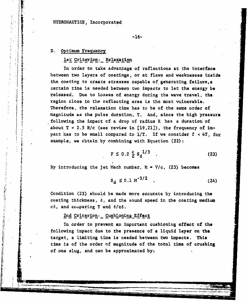
D. Optitnum Frequ'ency
lst Criterion: Rel'axation
In order to take advantage of reflections at the interface.. between two layers of coatings, or at flaws and weaknesses inside
"the coating to create stresses capable of generating failure,acertain time is needed between two impacts to let the energy bereleased. Due to losses of energy during the wave travel, theregion close to the reflecting area is the most vulnerable,Therefore, the relaxation time has to be of the same order of
I tmagnitude as the pulse duration, T, And, since the high pressure
following the impact of a drop of radius R has a duration ofabout T w 2.5 R/c (see review in (19,21]), the frequency of im-pact has to be small compared to l/T, If we consider f < 4T, forexample, we obtain by combining with Equation (,22).
F _ 0,2 s d (23)
By introducing the jet Mach number, M - V/c, (23) becomes
SSd : 0,1 M"3 / 2 , (24)
j' Condition (23) should be made more accurate by introducing thecoating thickness, 6, and the sound speed in the coating medium
[ cS, and comparing T and 6/*c6.
2nd Criterion: Cushioning Effect
*• In order to prevent an important cushioning effect of the. following impact due to the presence of a liquid layer on the* target, a limiting time is needed between two impacts. This
time is of the order of magnitude of the total time of crushingof one slug, and can be approximated by;
" - .. ...- - .-------- *-----.--I--- = .- ',
i i I i -'* " * i - -I*=I*'"l• -- -i-

HYDRONAUTICS, Incorporated
* -17-
T, 2R/V, (25)
The frequency of impact must therefore be smaller than 1/T1 ; andthus the Strouhal number is limited by:
S fd 'd (26)Wd2!
Taking Equation (.22) into account, (26) can be written:
Sd 0, 8 5 , (27)
With V - 500 ft/s and a k-it, diameter jet, the frequency ofmodulation should be smaller than 6000 Hz,
3rd Criterion'; Aerodynamic Effec-ts
* The aerodynamic effects are the principal limitations fork any of the approaches presented above, Once it is formed, a
drop or bunch cannot-keep its integrity for a long period of
time. The equilibrium between surface tension forces and aerob-dynamic drag forces is preserved as long as the Weber number:
2pV2RWe - (28)
is not bigger than a limiting value (250). This limits the
maximumn stable drop diameter to a fraction of microns! However,the distance needed for rupture is several times R, so that if
the target is close to the ragion where'bunching starts therupture can be avoided. In addition, drag forces can be reducudby trying to produce slugs with diameter, D, close to the jet
diameter, d. This can be written:
D1 ( , l, or S ? 0.66 (29)
.. , ,
W '.

HYDRONAUTICS, Incorporated
-18-
. which gives a frequency higher than 4000 Hz for the k-I, •.500
ft/s jet,
The preliminary criteria developed here are summarized in"Figure 5, in which the "optimum" working region, obtained byapplication of these criteria, is shown, This optimum regionis a narrow one; 0.66 < S : 0,85, and is based on a prelim,inary analysis. It is intended for guidance only, The actualoptimum range is probably broader and centered around 0.75, say
0.3 to 1,2,
E. Coomparison With Existi•ng Studies
F In his study, Nebeker [8) reports frequencies of the oscillationsbetween 12,000 and 20,000 Hz, with nozzle diameters of 0.06 and0.08 inches, and -pressures across the nozzle of order 7,200 psi.
Although the values of the frequencies are not too precise, themaximum and minimum values of the possible Strouhal numbers(S - fd/V) of the flows investigated in Reference [8] can beestimated to bet 0.06 • Sd _ 0.12,
A similar interpretation of the Erdmann-Jesnitzer (5] resultsshows that, with frequencies of 500 Hz and 2500 Hz, the Strouhalnumber was between 0.002 and 0.01. The same range of Strouhal]number is investigated by Janakiram [6) showing constant in-crease in cutting rates with increasing S
dAs we can see, these numbers are much smaller than the opti-
mum ones proposed above. As a result, although these studiesshowed large improvements in cutting rate with increasing fre-quency, their Strouhal numbers were always too small to identifythe existence of an optimum frequency,
FI
-••::7 7 2 ' •:• . .: : i •". " ' .. • ,., '••.. • •'
HYDRONAUTICS, Incorporated
-19-
IV. EXPERIMENTAL FACILITIES AND TECHNIQUES USED
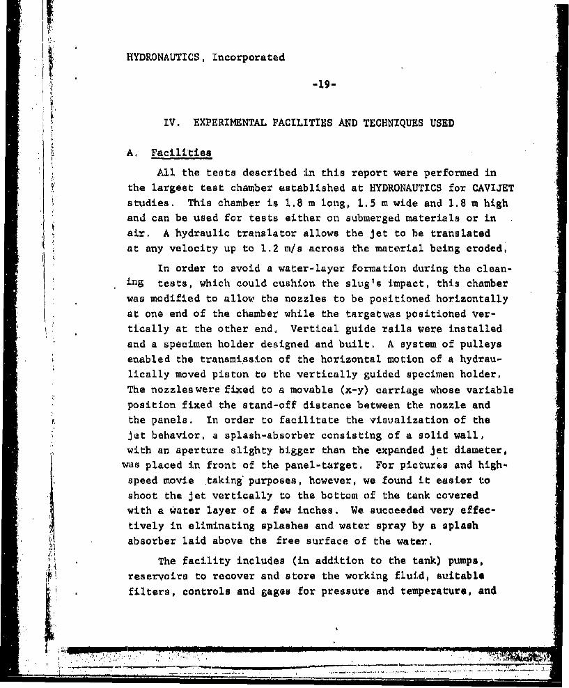
A. Facilities
All the tests described in this report were performed inthe largest test chamber established at HYDRONAUTICS for CAVIJETstudies. This chamber is 1.8 m long, 1.5 m wide and 1.8 m highand can be used for tests either on submerged materials or in
air. A hydraulic translator allows the jet to be translatedat any velocity up to 1.2 m/s across the material being eroded,
In order to avoid a water-layer formation during the clean-ing tests, which could cushion the slug's impact, this chamber
was modified to allow the nozzles to be positioned horizontally
at one end of the chamber while the targetwas positioned ver-tically at the other end, Vertical guide rails were installedand a specimen holder designed and built, A system of pulleysenabled the transmission of the horizontal motion of a hydrau-
* lically moved piston to the vertically guided specimen holder.
The nozzles were fixed to a movable (x-y) carriage whose variableposition fixed the stand-off distance between the nozzle and
the panels. In order to facilitate the visualization of the* Jet behavior, a splash-absorber consisting of a solid wall,
with an aperture slighty bigger than the expanded jet diameter,was placed in front of the panel-target. For pictures and high-
speed movie taking' purposes, however, we found it easier toshoot the jet vertically to the bottom of the tank coveredwith a water layer of a few inches. We succeeded very effec-tively in eliminating splashes and water spray by a splash
* 4 absorber laid above the free surface of the water.
The facility includes (in addition to the tank) pumps,* reservoirs to recover and store the working fluid, suitable
filters, controls and gages for pressure and temperature, and

HYDRONAUTICS, Incorporated
-20-
flow measuring devices, The pumps usedwereall of positive dis.placement design. Driven by a 75 kw (100 hp) motor is a 303 Z/m(80 gpm) capacity triplex, with a maximum pressure rating of15.2 MPa (2,200 psi). A diesel-driven, portable quintuplex,with various sets of plungers, allows a range of flow and pres.sure combinations in any pairing within the 112 kw (150 hp)power-envelope from 341 Z/m (90 gpm) at 3.7.2 MPa (2,500 psi) to76 k/m (20 gpm) at 68.9 MPa (10,000 psi).
In addition to this installation, an air-test facility waaused to rapidly evaluate the characteristics of various selfresonating chambers. A rectangular plenum supplied air to thedevice being tested. The pressure in the plenum was controlledwith a needle valve in the 0.2 MPa (20 psi) air supply line andwas monitored with a U-tube manometer. Flow from the test nozzledischarged to the atmosphere, Perturbations in the jet's axialvelocity were surveyed with a 25u diameter hot wire sensor.The detected signal was electronically processed. The raw volt-age signal from the Thermo-Systems Inc. (TSI Model 1050) hot-wire anemometer bridge was fed directly to a TSI Model 1060 RMS
' iVoltmeter, a spectrum analyzer (Hewlett Packard 3580A), and an
X-Y plotter. The mean and the root-mean-square anemometer volt-ages can be continuously recorded. The spectrum analyzer output,viewed on an oscilloscope, or recorded on the X-Y plotter, per-mits the detection of resonant frequencies in the perturbationvelocity; t.hese are manifested as sharp spikes or peaks in thespectra.
The other instruments and equipment used for this projectare high-frequency response pressure transducers (PCB Piezo-tronics, ICP Model 101A04, resonant frequency 400 kHz), a hbgh-speed camera, HYCAM, capable of 10,000 frames per second (or40,000 quarter frames per second), various still motion cameras,
-r'-- - -

HYDRONAUTICS, Incorporated
- 21-
a laser, a photo multiplier and a signal amplifier,
B. Techniques 'for Bunching' Detect'ion
Three ways of detecting the effective bunching of the jet
in discrete packets were used; two of them were optical and the
third acoustical. High quality visual observation of the phe-
nomena is the most reliable and the most comprehensive way for
studying the bunching characteristic both quantitatively and
qualitatively. High intensity, low duration (30ps) flash pic-
tures were taken, This method was satisfactory up to a jet
velocity of 300 ft/s. At higher velocities, the exposure time
became too long relative to the time scale of the phenomenon,
resulting in streaky and blurry pictures.
Another direct method of detecting the bunching of the
jet consisted of using a piezoelectric transducer protected by
-- . a layer of hardened epoxy as a direct target for the jet, or
a measuring device of the pressure transmitted through a pin-
hole drilled in a metallic target. While a continuovs jet gavea reasonably flat output signal a pulsed jet signal was char-acterized by spikes at constant time intervals corresponding
"to the oscillation frequency, A frequency analysis of the
amplified output of the transducer proved to be a satisfactory
means of detecting the presence or not of discrete frequencies,
and thus of bunching, in the jet. Unfortunately the use of
transducers as direct targets seems to be (at least in the way
we performed the tests) a poor and rather expensive idea. The
passively generated slugs apparently produce shock waves high
enough to destroy probes capable of a nominal pressure of
i0,000 psi (PCB Piezotronics, ICP Model 101A04). Aftee de-
stroying two probes, wc •topped using this technique. The use
of the transducer fitted under tha target and communicating
" C•, , I, I I.|

HYDRONAUTICS, Incorporated
-22-
with the impacting jet by means of a pin-hole presented no dif-
ficulties, Atiother transducer flush-mounted inside the straight
tube of length L (Figures 2 and 7) was successfully used to cor-
relate the pressure fluctuations and their characteristic fre-
quencies with those measured in the jet itself.
The second optical method proved out to be the fastest
and the most practical: a laser beamwasshone through theijet;
the transmitted beam of light was amplified by a photo multiplier,
(PM) and the signal analyzed. In the absence of excitation and
at lower stand-off distances the jet is continuous and little
light crosses to the PM. At greater stand-off distances the
jet integrity is destroyed and the PM signal looks very random.
However, when the jet is excited the laser beam is periodically
interrupted by the existing slugs. In this case the signal
displays a characteristic periodicity, and its frequency spec-
trum correlates highly with the pressure transducer signals and
"the slug pictures as shown below, Figure 6 summarizes the
experimental set-up described above,
C. Tested Nozzles
Before we made the final choice of the nozzle shapes to
test for this study, the performance of several existing nozzles
was observed. These nozzles were developed earlier at 14YDRO-
NAUTICS in order to increase the erosive capabilities of sub-
merged jets by enhancing cavitation in the shear layer. Both
PULSER and PULSER-'"ED (Figure 2) configurations were tested
and compared with the behavior of the same nozzles in the
absence of the Helmholtz chambers, all other dimensions and
flow conditions being comparable. Single flash pictures of
the jets showed a radical change in their appearance. The
free surface of the nonexcited jet looked smooth and stretched,
but these jets were diverging substantially. The excited jets
S -- __ ...------ , --.. , - * ' ----- *,, ... .. ..

HYDRONAUTICS, Incorporated
-23-
"exhibited bunching characteristics but were spreading out veryearly, a few jet diameters downstream of the exit, In these
preliminary tests we did not pay any attention to the inlet con,
ditions, the smoothness of the flow and the nozzle shape, Basedon these observations, .it seemed fundamental to design a nozzlecapable, in absence of excitation, of attaining a large stand-offdistance before starting to spread. A survey of the literatureconfirmed the great influence of the inside contour of thenozzle on the maximum reach of the jet, A CAVIJET shape with
a contour closer to an ellipse rather than to a circle shouldgive the greater reach even when compared with the well-knownRouse shape [22]. As time would not have allowed for systematicresearch on inlet contours, we chose an elliptical CAVIJET shapesimilar to the one selected in a recent review article on the
* subject [22]. A Leach and Walker nozzle was also used forcomparison purposes.
In order to generate comparable data between the various
configurations tested, the nozzle assembly represented in Figure7 was constructed. For a given inside shape of the nozzle,
the lip thickness,e,could be changed by replacing piece B.* This also allowed testing various contours of the nozzle shape.
The jet wasexcited either by inserting piece A in Figure 7(PULSER-FED configuration) or by the correct choice of e andthe outer contour of the lip in order to provide a feed-back
mechanism to the organ-pipe of lengthL. In absence of piece Aand when e is zero we have our basic pliai CAVIJET with a longe we obtain an ORGAN-PIPE nozzle and when A is present wegenerate a PUISER-FED nozzle. A jet would be nonexcited bothwhen part A is removed and e is zero or the nozzle has a clas-,
Ssical shape (e.g.,Leach and Walker nozzle).
In order to be able to generate a controlled excitation
T-~,-___ii__ -.. -i Y--l::~ I

HYDRONAUTICS, Incorporated
-24-
corresponding to the resonance characteristics of the system,the ratio Di/Da (Figure 7) was chosen big enough to ensure agreat variation of the acoustical impedance at the inlet sectionof the nozzle, This condition limited the highest value of the,jet diameter to 0.185 inches for a maximum pressure drop acrossthe nozzle of 2,000 psi, Bigger diameters can be studied infuture work at these pressure provided that a modification ismade to the diameter of the feed tube,
Another important condition for a good control of the acous-tical behavior of the jet is a "clean" long straight inlet tubeof diameter D, upstream of the nozzle. A tube 11.5 inches longwas used' for all configurations tested. Its diameter was 1.3.inches for ORGAN-PIPE and PULSER-FED SERVOJETS and 0.53 inches
for nonresonating jets. The diameter, D2 , of the exit tube wasalso 0.53 inches and its -length was 4 inches,
As we discuss below two series of nozzles were used, Thefirst was designed for low velocities and allowed assessment ofthe validity of the measurement techniques and characterization
of the jet flow oscillations. The design of the second serieswas based on the knowledge acquired from the first nozzles and
* considered higher pressures to enable paint and coating removal.Due to the flow rate limitation of the pump, smaller jet diameters
were imposed as well as relatedi changes in the resonating chambers,
For visualization and techniques evaluation purposes theHelmholtz resonator chamber and the organ-pipe characteristics
were chosen to give optimum performances at a Mach number of 0.1,which corresponds to a value of Ap u 1600 psi. Based on the
-* equations presented in Section II, this corresponds to the dimen-sions: d, 0.23 inches, d 2 = 0.2.8 inches, dT 0.79 inches andt 0.37 inches. The nozzle shapes investigated were an elliptical
I , I . . . . .. .1 ,
HYDRONAUTICS, Incorporated
-25-
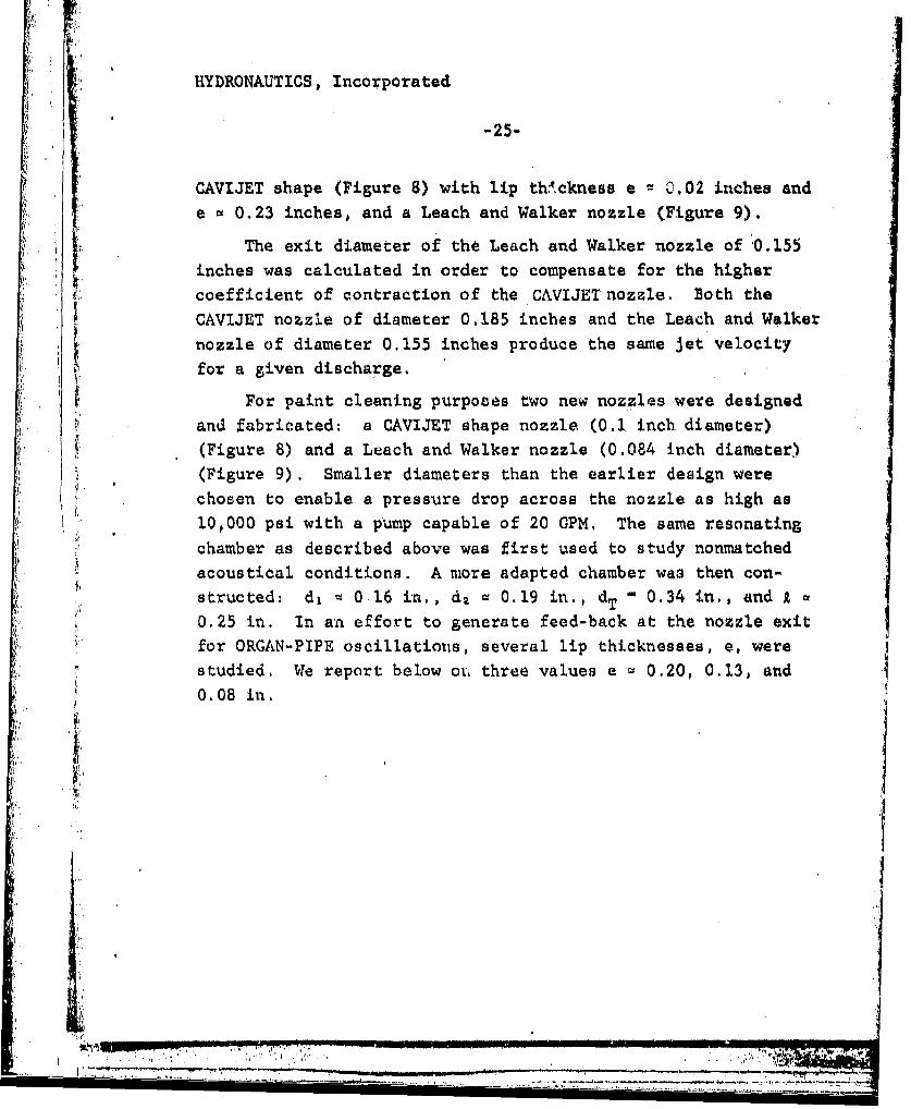
CAVIJET shape (Figure 8) with lip th4.ckness e 0,02 inches ande • 0.23 inches, and a Leach and Walker nozzle (Figure 9).
The exit diameter of the Leach and Walker nozzle of 0.155
inches was calculated in order to compensate for the highercoefficient of contraction of the CAVIJET nozzle. Both the
t. CAVIJET nozzle of diameter 0,185 inches and the Leach and Walkernozzle of diameter 0.155 inches produce the same jet velocityfor a given discharge.
For paint cleaning purposes two new nozzles were designedand fabricated: a CAVIJET shape nozzle (0.1 inch diameter)(Figure 8) and a Leach and Walker nozzle (0,084 inch diameter)(Figure 9). Smaller diameters than the earlier design were
chosen to enable a pressure drop across the nozzle as high as10,000 psi with a pump capable of 20 GPM, The same resonatingchamber as described above was first used to study nonmatchedacoustical conditions. A more adapted chamber was then con-structed: d, - 0 16 in., d2 = 0.19 in., dT 0.34 in,, and 2
0.25 in. In an effort to generate feed-back at the nozzle exitfor ORGAN-PIPE oscillations, several lip thicknesses, e, werestudied. We report below or, three values e 0.20, 0.13, and0.08 in, j
-'.
.,;' !:! "I• ' " . . .... . . . . . . _ ' 1!• J • IJ I II . .. .... .. . .. .. . ....
-... . .. . .. . ... ., ... .. . . .. .. - i • : : i - i ... .""• -: i " -i". . .......i ' - i -'i "'' .. .. . . . -"

HYDRONAUTICS, Incorporated,
i 'liI -2 6,,
V, EXPERIMENTAL RESULTS
A. Flow Co'rtec'tions
In order to make justifiable comparisons between the dif.
ferent nozzles used, two corrections were applied, The first-
one dealt with two nozzles of different shapes (ie., CAVIJET andLEACH & WALKER) and thus of different discharge coefficients.
These discharge coefficients were determined using the air facil-
ity and, as stated before, the diameter of the LEACH & WALKER
nozzle was chosen smaller in order to compensate for this dif-ference, With the final choice the LEACH & WALKER nozzle hadthe same flow rate and the same jet velocity as the corresponding
CAVIJET for a given pressure drop across the nozzle,
The second correction was concerned with the losses intro-
"duced by the presence of the PULSER-FED Helmholtz chamber in the
feed-tube of the nozzle. The air facility was used to determine
the discharge curves (Figures 10 and 11) for the considered noz-zles, with and without the Helmholtz chamber. A comparison between
the two curves allowed for an equilibration of the total pressure"drop across the two compared nozzles in order to obtain the same
exit velocity. For the low velocity, larger diameter first seriesof jets (SERVOJET,d n, 0.185 in., LEACH & WALKER, d w 0.155 in.)Figure 10 presents the discharge curves and shows the presence
of losses as high as 24 to 28 percent. A mean value of 26 percent
was used in subsequent tests. To obtain the same jet velocity
one has to use a pressure drop across the nozzle assembly 26
percent smaller for an ORGAN-PIPE or a plain jet than for'.a
PULSER-FED jet,
As can be seen in Figure. 11 the losses were substantially
smaller for the second series of jets -high velocity, emaller
diameters (SERVOJET, d • 0.1 in., LEACH & WALKER, d • 0.084 in,)
* .IY.. .. " ,-"i , u . . . . _ • .-t il

HYDRONAUTICS, Incorporated
-27-
A mean value of six percent correction was applied in all ofthese tests. The oscillatory behavior of the discharge curve icvery interesting to notice and can be related to later discussionson ORGAN-PIPE SERVOJETS in this report, Indeed, these oscillations'are directly related to an ORGAN-PIPE resonance of the nozzleassembly even without the Helmholtz chamber. The pressure fluc-tuation curves in the upper part of Figure 1i show the intensityof these oscillations. However, this did not alter our testssince the ORGAN-PIPE SERVOJET nozzle which was studied had pro-
duced highly structured resonating air jets in the submergedcondition; air-air, while it was very poorly structured in the
nonsubmerged conditions: water-air (see Figure 26),
B. Photographic' Evidence
We highlight in this paragraph the observations we:,,have madeconcerning the appearance of water-in-air jets in the presence
and in absence of self-excitation. We will present pictures ob-
tained with a single flash lighting 4ith a IAMIYA camera andKodak 4X black and white films. We also took some infra-redpictures in an effort to minimize the influence of the mistsurrounding the jet. However, in the pressure range over whichwe tested, this technique did not show a noticeable advantage,Three high-speed movies of the jet with the HYCAM were exposed,but the picture quality of the still pictures was better becauseof the shorter exposure time of the flash relative to the shutterspeed of the HYCAM.
Figure 12 shows the oscillations and production of dropletsfor jets of relatively low speed, The first case (Figure 12a)illustrates the phenomenon of Jet breakup by the Rayleigh in,stability, The two other pictures show the 'dynamical instability
[19-20] which is followed by the' rupture of the jet into slugs,
Here the velocity is still relatively low so that air entrainment
1 ". ' .. .. )•- .•v .++,, . ,....... -•, .... . ,..iL ._,_r'.•

•I HYDRONAUTICS, Incorporated
-28-
I and mist production do not affect the jet's appearance.Figures 13 and. 14 compare, at two different velocities, the
structure of a self-oscillating jet with that of a nonexcited jetobtained with the same nozzle. For all the Jets seen in these
S~figures the same Leach and Walker exit nozzle was used. The only
modification between the oscillating and nonoscillating configu.rations is the existence of the resonance chamber in the former(piece A, Figure 7). The presence of discrete structures or"packets of water" is clearly observed for both values of thepressure drop, Ap, across the nozzle assembly (600 and 900 psi)
for the SERVOJETS. As the dominant frequency is practically thesame in the two cases (4 kMz), the distance between the slugs isseen to increase with V. Here, as often observed for severalstudied configurations, a subharmonic (0,15 • Sd 5 0.2) to theknown fundimental jet turbulent frequency (Sd a 0,3) for submerged
Sjets, is I esent. This is due to the fact that for these nozzles(d, w 0.23 in., d v 0.185 in.) the Strouhal number based on theupstream conditions, Sd (i.e. , on the.'j-t issuing from d1) is
* twice as big as Sd. We bave thus the more usual result (0,35* Sd S 0.4). Another factor which needs more investigation is
the value of the predominant Strouhal number of the nonexcitedwater-in-air Jet which, as we discuss below, is not the same asfor a submerged Jet. The bunching frequency based on the distancebetween two siugs and the jet velocity matches perfectly, withinthe accuracy of error measurements, the frequency inside the tube.As an example, Figures 13b, 14b, and 14 c give a frequency of3.75 kHz while the measured dominant frequencies in the tube are4 r--d 3.8 kHz.
The next two Figures, 15 and 16, show the case of wellstructured PULSER-FED SERVOJETS with a CAVIJET nozzle, Verydistinct structuring is observed as well as a "fanning" of the
*~~~ý 70 _ _ _ _ _

HYDRONAUTICS, Incorporated.
-29-
slugs due to air drag. Figure 15 corresponds to the low-velocity,larger-diameter nozzle in its optimum working region (maximumoscillation). Figure 16 corresponds to the smaller-diameter
nozzle in its first peak of oscillations (see Figure 25, M * 0.07).
. In both figures the following description of the modulated Jet
applies: first, "bulbs" appear in the core; next, ,the bulbs are
detached into slugs; and then they become greatly deformed dueto air drag, The maximtm energy of impact is obtained Just in
the detachment region, while cleaning rates indicate higher ef-
ficiency in the "fanned" region.
C, Pressure Fluctuation 'and' Laser' Beat lbte'rtuption
As described in Section IV, paragraph B, and sketched in
"Figure 6, a pressure transducer used as a target and another one
installed in the nozzle tube allowed measurement of the acoustical
properties of the oscillations. Another direct technique to de-
tect the bunching characterisitcs of the jet was based on inter-
rupting a laser beam and analyzing the transmitted light variations
with time. We present here the results of these measurements,
Figure 17 shows the frequency spectrum, for the nonexcited
jet (CAVIJET shape, Figure 10, with d w 0.185 in., e m 0.02 in.),
of the pressure oscillations at the location of the pressure trans-
ducer in the feed tube. This spectrum did not change when changing
the length of this tube and seemed to arise from a feed-back me-
chanism from the jet oscillation back to the tube (see next section
D). Let us note, however, that the relative amplitude of theoscillations, p'/Ap, is only 0.4 percent.
Figure 18 preselits, for the same jet exit velocity do in
the preceding figure (V v 360 ft/a), the noise frequency spectrum
for the self excited jet. These self-oscillations are induced
by inserting the Helmholtz chamber in the nozzle assembly
________________.: iA,

HYDRONAUTICS, Incorporated
-30-
(Figure 7). (The pressure drop across this nozzle assembly isincreased to compensate for the los3es and to obtain the samejet exit velocity.) Here, the frequency peaks are very sharp"and discrete and the pressure fluctuations are an order of magni-tude higher than for the plain jet (p'/Ap • 5,2%), The locationsof the frequency peaks are a result of the choice of the geometryof the pulser chamber, It was designed to function at a Strouhalnumber, SV, based on the chamber length, which is a multiple of0.3, and to resonate (give maximum amplification) at Ap - 1600psi, and a Strouhal number, Sd' based on the upstream diameter
"d, (see Figure 7) of value 0,5, Due to this particular choicewe have S 3 d and the three observed peaks happen to be atS 0.36, 0.60, and 0,96 which correspond to the first, second,and third mode of the pulser chamber (presence of 1, 2, or 3 ringvortices between orifices d, and d2 ).
Figures 19 and 20 show, for approximately the same jetvelocity, (V 210 and.205 ft/s) how the frequency spectrum ofthe pressure signal in the nozzle tube strongly correlates withthe spectra of both the impact pressure oscillations on a trans-
1' ducer-,target (Figure 19) and the modulation of the laser beam in-terrupted light (Figure 20), This result is very encouraging
for future studies since one of these measurements is sufficientand gives the needed information on the frequency concerning thetwo others. This c-orrelation between optical and acousticalobservations was used for the remainder of the study, to generate.
,t high pressure self oscillating jets. Another observation fromFigure 19 is that the pressure fluctuations are largely amplifiedbetween the pipe and the optimum distance (X - 7 in,). A multi-plication factor of four has affected the value of pl/Ap, Wealso observe that this optimum standoff distance corresponds tothe one predicted by Equation (19), Indeed, wiLh
I ' .-.- .- , -,~ '7 -
,' .~.... ... • :

1HYDRONAUTICS, Incorporated.
-31-
' V d 1 (30)
(p'; amplitude of pressure oscillation, AV: double amplitude of
velocity oscillation), the needed pressure oscillation to obtain
X 7 in. and Sd = 0.33, with d = 0.185 in, is:
pt /Ap 0,04, (31)
which is very close to the pressure oscillations measured in the
pipe (3.5%).
In Figure 21, the pressure oscillations in the tube are com-
pared with those sensed by a transducer fitted in a flat plate
and used as a target. The frequency spectra at four different
standoff distances are compared. An excellent correlation between.
all these spectra can be seen. Some differences can, however, be
observed. First, the harmonic, f u 3.1 kHz, Sd • 0.20 which
exists in the tube has practically disappeared in the Jet itself.
The self-oscillations of the system have selected the main tur-
bulence frequency of the jet, f v 5.5 kHz, Sd ti 0.38. However,
the second harmonic and, to a lesser extent, the third harmonic
which are very weak inside the tube are strongly amplified in
the jet. Figure 21 also gives valuable information on the struc-
ture of the jet and on its "aggressivity" at various standoff
distances, X. At too small or too large distances from the nozzle
exit the impacting pressure oscillations, as well as the energy
content of the main frequency, are relatively low. In the pre-
sent case, the shape of the nozzle is a CAVIJET shape, with d -
0.185 in., V u 220 ft/s, and the pressure fluctuations observed,
p'/Ap, were 2.2% at X - I in., and 2.0% at X - 15 in. The optimum
standoff distance in this case appears from these measurements
to be at X N 7 in, (X/d = 38) where p'/Ap = 10%, for pressure
fluctuations inside the tube of only 2,5%.
', ,,2-"
, , I 2
t -,. , ,

HYDRONAUTICS, Incorporated
-32-
Figure 22 shows a correlation between the frequency spectra
of the laser transmitted light signals at two different distances,
X, from the nozzle exit, and the spectrum of the pressure fluc-
tuations inside the tube. A perfect correlation in the position
of the peaks can be observed, Here, the subharmonic of the main
frequency (7.1 kHz, Sd w 0.37) is predominant in the pipe oscil-
lations. This predominance is also reflected in the slug for-mation and thus in the interrupted laser beam signal, The
structuring is observed to have ameliorated between the two in-
* spected locations X 1 10 in. and X - 16 in,
The use of pressure transducers as direct targets for the
oscillating jets was limited to a jet velocityof 320 ft/s (Ap
700 poi). The water-hammer pressure due to the impact of a s'lug
at such a speed is approximately 23,000 psi. Even with a shock
absorption factor of two this pressure exceeds the limiting
dynamic pressure of the transducer which is 10,000 psi. The
laser interruption technique, however, does not hbive the intrinsic
"limitation of the pressure transducer technique. The only limi-
tation for the laser arose from practical reasons related to the
use of the tank. This tank was covered in order to reduce en-
vironmental noise; during a test run it became foggy and water
condensation droplets obscured the PM view. The system worked
satisfactorilyupto a jet speed of 350 ft/s. Above this speed
only diffuse light with white noise (very broad frequency con-
tent) passed through the PM amplifier. The same type of spectrum
was obtained with a plain nonexcited jet. This was the case for
all the jets tested (Leach and Walker, ORGAN-PIPE, e a 0.02 and
e 2 0.032 in.) in the absence of a Helmholtz chamber. This
fogging problem can be alleviated by working in an open tank
or outdoors. The use of a metallic plate with a drilled pin
hole, as a protective rnians for the transducer, worked out very
satisfactorily- for jet pressures as high as 10,000 poi. This
4.. . ., , , . .. ' , " ... ,!•i i •!, i• ,'.-.
HYDRONAUTICS, Incorporated
-33-
technique was mainly used to explain the results obtained withpaint cleaning and is presented below.
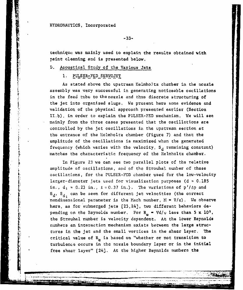
D. Acoustical Study of the Various Je'ts
1. PULSER-FEDSEBRVOJET
As stated above the upstream Helmholtz chamber in the nozzleassembly was very successful in generating noticeable oscillationsin the feed tube to the nozzle and thus discrete structuring ofthe jet into organized slugs, We present here some evidence andvalidation of the physical approach presented earlier (Section1I.b), in order to explain the PULSER-FED mechanism. We will see
mainly from the three cases presented that the oscillations arecontrolled by the jet oscillations in the upstream section at
the entrance of the Htelmholtz chamber (Figure 7) and that the
amplitude of the oscillations is maximized when the generatedfrequency (which varies with. the velocity, Sd remaining constant)
matches the characteristic frequency of the Helmholtz chamber.
In Figure 23 we can see two parallel plots of the relativeamplitude of oscillations, and of the Strouhal number of theseoscillations, for the PULSER-FED chamber used for the low-velocity
larger-diameter jets used for visualization purposes (d t 0.185in., d, ! 0.23 in., P-0.37 in.). The variations of p'/6p and"Sd, Sd can be seen for different jet velocities (the correctnondiraensional parameter is the Mach number, 1 - V/c) . We observehere, as for submerged jets [23,24], two differeit behaviors de-pending on the Reynolds number. For Re M Vd/v less than 5 x 10s,the Strouhal number is velocity dependent. At the lower Reynoldsnumbers an interaction mechanism exists between the large struc-"tures in the jet and the small vortices in the shear layer. Thecritical value of Re is based on "whether or not transition to
turbulence occurs in the nozzle boundary layer or in the initial
free shear layer" (24]. At the higher Reynolds number& the
HYDRONAUTICS, Incorporated
-34-
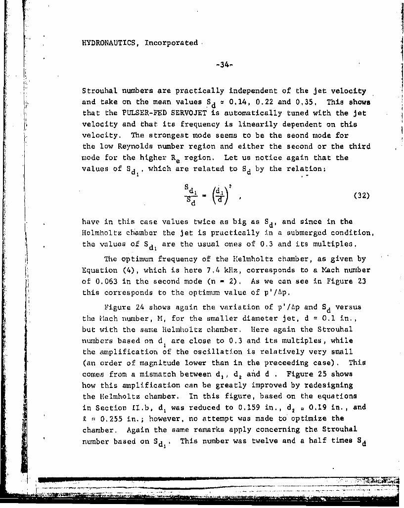
Strouhal numbers are practically independent of the jet velocity
and take on the mean values Sd 0,14, 0.22 and 0,35, This shows
that the PULSER-FED SERVOJET is automatically tuned with the jet
velocity and that its frequency is linearily dependent on this
velocity. The strongest mode seems to be the seond mode for
the low Reynolds number region and either the second or the third
mode for the higher Re region. Let us notice again that the
values of Sd, which are related to Sd by the relation:
(32)
have in this case values twice as big as Sd, and since in the
Helmholtz chamber the jet is practically in a submerged condition,
the values of Sd are the usual ones of 0.3 and its multiples.
The optimum frequency of the Helmholtz chamber, as given by
Equation (4), which is here 7,4 kHz, corresponds to a Mach number
of 0.063 in the second mode (n - 2). As we can see in Figure 23
this corresponds to the optimum value of p'/Ap.
Figure 24 shows again the variation of p'/Ap and Sd versus
the M~ach number, M, for the smaller diameter jet, d = 0. in,,
but with the same Helmholtz chamber, Here again the Strouhal
numbers based on d are close to 0.3 and its multiples, while
the amplification of the oscillation is relatively very small
(an order of magnitude lower than in the preceeding case). This
comes from a mismatch between d1 , d 2 and d . Figure 25 shows
how this amplification can be greatly improved by redesigning
the Helmholtz chamber. In this figure, based on the equations
in Section £I.b, d, was reduced to 0,159 in., d2 v 0.19 in., and
9 r 0.255 in.; however, no attempt was made to optimize the
chamber, Again the same remarks apply concerning the Strauhal
number based on Sd,. This number was twelve and a half times Sd
• i,'.i' I'11 " -• :-:L II1] ... ... I,,"'-:' . -.. -. ' -' . .-. . .. . . .-- ': , , ,"i• ,'NOW
77 7 [ J • ... ] ]l• l • i • il --

HYDRONAUTICS, Incorporated
S~-35-
in Figure 24 and is here (in tisure 25) reduced to four times Sd.
More research needs to be done on the optimization of this ratio,
chosen arbitrarily here. The three peaks in the pressure oscil-
lations were picked for comparative paint removal testa.
2. ORGAN-PIPE_ SERVOJET
The feed-back mechanism seems to be extremely hard to achieve
in the water-in-air case., Two different sizes of e (Figure 7)'I were tested for the larger-diameter nozzles (d = 0.185 in.) and
as discussed abo4.,e only very small oscillations (0.4%) could be
achieved in the nozzle tube. More Lurprisingly, the frequency
of these oscillations was independent of the tube length. Moretests were conducted for the high-velocity small diameter-nozzles
(d 0,1 in.) and the results are summarized in Figure 26, Three
values for the lip thickness, e, are shown and the amplitude ofoscillations (maximum 0' 55%) versus Mach number are presented,
One can see that the effect of e is very small, which implies
that strong oscillatiosn through feed-back have not yet beenachieved.
Another striking factor is the constancy of the frequencyemitted. Several ,peaks exist in the spectrum at the constant
frequencies 3, 4, 10, and II kHz. These frequenciec are inde-
pendent of the jet velocity and of e. This suggests that the
only noisi fed back in the nozzle is a jet noise which might beorganized through 'acoustic triggering and not vortex transport,as was discussed earlier. in this case the "Strouhal number" to
consider would be based on the speed of sound (rather than the
aet velocity) and would remain constant relative to the Mach
number. This idea is reinforced by the oscillations detected
( . in the Leach and Walker nozzle which are of f.he same order as
those in the supposed ORGAN-PIPE nozzle, and have in addition
the same frequencies. Since further research on the nozzle
T- --

HYDRONAUTICS, Incorporated
-36-
shape was beyond the scope of the present effo,.t, we consideredonly PULSER-FED nozzles for the following part of the program.
E. Paint RemoVal' Tests
We performed all 'he self-resonating jet paint removal testswith the PULSER-FED SERVOJET, d a 0.10 in., and compared theseresults with the corresponding LEACH & WALKER nozzle, d = 0.084in. All the tested panels. were provided by the North IslandNaval Air Station, in San Diego, California. The a',utninum panels
were actual aircraft panels with MIL SPEC coatings,
The graphite-reinforced plastic panels, which had an epoxyprimer and a polyurethane ton coat, were tested in our modifiedlarge test chamber, The punel edgeis were protected with a glass-reinforced adhesive tape to minimize water penetration under theunprotected edge. This water intrusion tends to dtelaminate anddamage these panels. Each test panel was first mounted on ametallic plate, then placed vertically and transversed at a con-stant velocity perpendicular to t-he impacting jet. Several pumppressures and standoff distances between the nozzle and the panelwere tested. Paint removal started to occur on these panels whenpeak pressure oscillations were achieved (see Figure 25) at trans-lation velocities of 0.5 in./s for the first effective peak(Ap 3,420 psi) and 1.5 in./s for the second peak (Ap u 5,220psi).
The test plan involved investigating this second peak, byrunning a series of various standoff distancts at a fixed tans-lattoen velocity and thus determining the optimum standoff. Thiswas repeated for both the SERVOJET and LEACH & WALKER nozzles,in order to make comparisons at the optimum performances of eachnozzle. Lnfortunately we discovered after a few tests that thisobjective could not be obtained with tha originals panels we hadreceived from the Navy, due to large nonuniformities in the

HYDRONAUTICS, Incorporated.
, -37-
erosion strengths of both the paint and the carbon-reinforced
, plastic substrate.
SFigure 27 clearly illustrates these nonuniformities, Com-paring cleaning paths 1 and 3 one can see that while 3 is run ata higher translation velocity for the same speed of the PULSER-FED SERVOJET the panel was badly damaged. Run 1, which would beexpected to be a more damaging test, has a very clean path whereinboth the top coat and primer have been removed with no damage tothe substrate. The same type of discrepency can be seen againbetween Runs 4, 5, and 3,
Figure 28 shows another example of the difficulty of inter-preting any results with these panels. A consistent pattern isseen between Runs 1, 2, and 3i increase of Ap and a corresponding
increase of cleaning width. However, Runs 1 and 5, 2 and 6 whichSi"are at the same conditions show great differences in the cleaning
rates. On this same panel a Leach and Walker nozzle at the sameAp cut through the panel at the extreme right end of the photo-
graph. To give an indication of the cleaning rates Runs 3 and 7'correspond to a rate of about 15 ft 2 /hr.
Fortunately the aluminum panels seemed to be more consistentand the tests were repeatable, at least on the same panel.important differences existed, however, between the several panels.Indeed, panel V for example (Table 1) had three MIL-C-83286 poly-urethane-baqed coatings above the yellow MIL-P-23377 epoxy,,poly-imide priuker: a gray top coat of about 50p thickness, two silvercoats tan 100lj thickness and silver 50p thickness. Panel VIZ,"had the same number of coats but the yellow "primer" was on top
of the silver coat. Panel V1 had just two coats.a grey topcoat and a yellow primer. The results and the conditions forthe path cleanings on these three panels are elummarizid 1in Tables
1 to 3. We will describe and interpret below some Of the&e
!, ,.-. . , ' • • .. L , . ,' ,'.•,'• ' . ... .. , . . , .. . O .. r.,O . ,, q" ..

HYDRONAUTICS, Itncorporated
-38-
results, concentrating mainly on panel V (Figures 29 to 327.
"Figure 29 gives an overall view of the whole panel, Thenumbers written near each path correspond to Table 1, where thetest conditions are presented, All the cleaning paths on this
panel were performed at the satae jet velocity, niamely a pressuredrop across the Leach 'and Walker noz.,'.e of about 5,100 psi anda slightly higher (+6%) Ap for the PULSER-FED SERVOJET, to com-pensate for pressure losses in the Helmholtz chamber. The sametranslation velocity was considered in. all cases, 1 in./s, andthe main variable was the standoff distance, X. Visually, theoptimum standoff distance for the PULSER-FED SERVOJET was deter-mined to be about 14., but a more careful analysis of the cuttingrates showed it to be at a higher value of X. To determine the
optimum standoff for the Leach & Walker nozzle another panel, VIwas used. A value of X,close to 10 in. was obtained. A fewother runs were ruade for confirmatý,on on panel, V, and a,,value'closer to 13.5 inohes was obtained (see paths 3C and 8B in Figure.29). Figure 30 compares the two nozzles when the standoff distancevaried between 11 and 23 in. The PULSER-FED nozzle is seen togive a more uniforta, wider path, A close look shows also thatthe removal rate of the third coat (see Figure 33) ic in thiscase almost four times greater, Figure 31 shows very clearlythis advantage of pulsing the jet when one compares the two paths8B and 3C, both. taken at the apparent optimum standoff distance"of 13.5 in. Figure 34 shows two photomicrographs of the coatingappearance in the jet cleaned path. While picture A4b showis aclean yellow primer, slightly pitted, in the case of the PULSER-FED SERVOJET, picture 34a shows the remainder of the third coatin the LEACH & WALKER case.
Figure 32 shows the same re'sults as above for severail dtend-off distances. As examples paths 3B and lAO which cleaned with
HYDRONAUTICS, Incorporated
-39-
a PULSER-FED CAVIJET, have better cleaning rates than path 2A
which is a PULSER-FED LEACH & WALKER or than path 3A which is a
plain LEACH & WALKER. All four runs were at a 5 in. standoff
distance. The same applies 1.r pathi 5B and 4A, with standoff
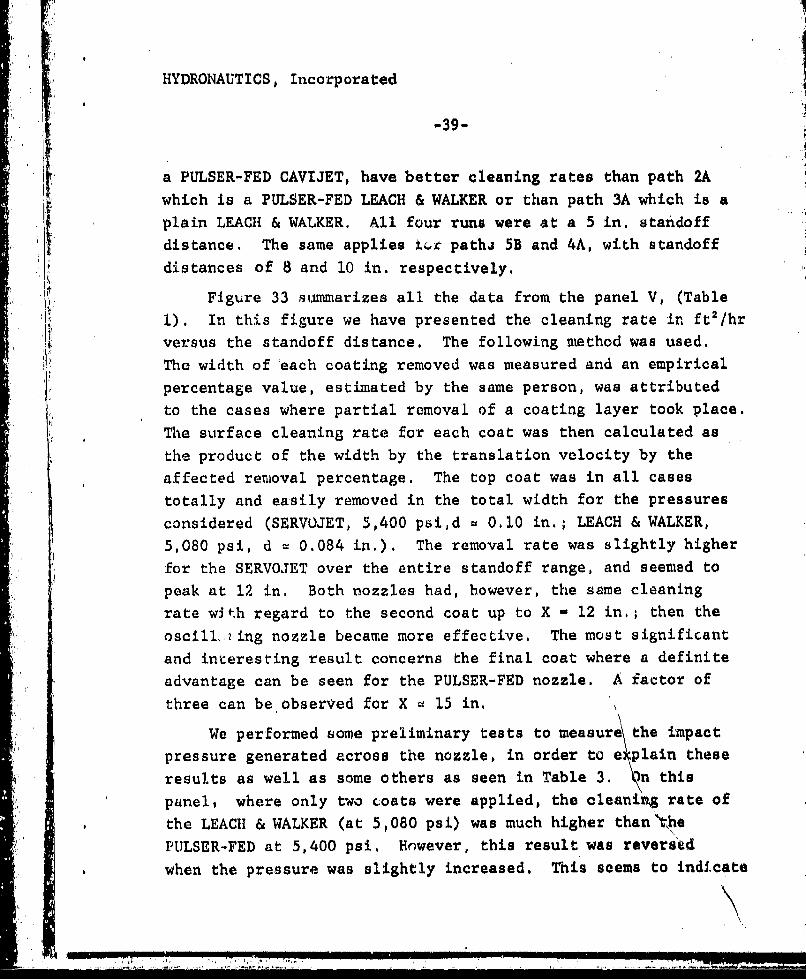
distances of 8 and 10 in. respectively.*•/ Figure 33 summarizes all the data from the panel V, (Table
1). In this figure we have presented the cleaning rate in ft 2 /hr
versus the standoff distance. The following method was used.
The width of each coating removed was measured and an empirical
percentage value, estimated by the same person, was attributed
to the cases where partial removal of a coating layer took place.
The surface cleaning rate for each coat was then calculated as
the product of the width by the translation velocity by the
affected removal percentage. The top coat was in all cases
totally and easily removed in the total width for the pressures
considered (SERVOJET, 5,400 psi,d u 0.10 in.; LEACH & WALKER,5,080 psi, d 1 0.084 in.). The removal rate was slightly higher
for the SERVOJET over the entire standoff range, and seemed to
peak at 12 in. Both nozzles had, however, the same cleaning
rate with regard to the second coat up to X - 12 in.; then the
oscill,.zing nozzle became more effective. The most significant
and interesting result concerns the final coat where a definite
advantage can be seen for the PULSER-FED nozzle. A factor of
three can be observed for X v 15 in.
We performed some preliminary tests to measure the impact
pressure generated across the nozzle, in order to e-plain these
results as well as some others as seen in Table 3. )n this
panel, where only two coats were applied, the cleaning rate of
the LEACH & WALKER (at 5,080 psi) was much higher than thePULSER-FED at 5,400 psi, However, this result was reversad
when the pressure was slightly increased, This seems to indicate
I' 11.I H ..... '

HYDRONAUTICS, Incorporated.
-40o
that the threshold of paint removal was not attained for the
SERVOJET for the lower 4p and thus the cleaning rate was neglible;
Once this threshold was passed the oscillations dramatically in-
creased the erosion rate.
The pressure measurements involvedmoving the metallic target
with a pin hole and a transducer in front of the jet and measuring
the variation of the impact pressure with the radius, for bothjets. Two comparative profiles are shown in Figure 35 for bothjets, The two upper profiles correspond to the optimum cleaning
rate case presented above (Figure 31), Surprisingly, the maximum
pressures are much higher for the LEACH & WALKER than for the
PULSER-FED nozzle, while the erosion rates are the opposite.
A probable explanation is the fact that in one case the impacts
are rather random, while in the excited nozzle case discretefrequencies of 10 and 25 kHz are present -- which create stress
amplification in the coating. This requires more understanding
and is a key element for any future development of the self-re-sonating cleaning Jets.
• -- .'..,.!
, -,
j,., ,!,
i4

HYDRONAUTICS, Incorporated
-41-
VI. CONCLUSIONS
We have demonstrated in this work the feasibility ofpassively inducing self oscillations in a nonsubmerged water jet
for paint removal applications, Two systems were investigated:
a) the insertion of a Helmholtz resonator.upstream in thefeed tube leading to the nozzle; PULSER-FED SERVOJET.
b) the generation of organ-pipe resonances in the nozzletube through a feed-back mechanism at the nozzle exit,
The first system was very successful in achieving thn. jetstructuring and results related to this system are thoroughly
described in this report, The second system was less successful
due, in our opinion, to lack of time available for researching
an adequate exit shape. Similar research done at HYDRONAUTICS
on submerged jets has shown great success in achieving high
levels of self oscillations; but a large effort had to be spentin finding the optimum lip thickness, e,and the nozzle shape.
The problem was complicated by the fact that preferred frequencyof a free water-in-air jet is different from the submerged case,
An ORGAN-PIPE system, if successful, would have the great advan-
tage of very low losses.
Several techniques were used to determine the bunching char-
acteristics of the SERVOJET and have all shown perfect correl-
ations in the frequency spectra, Pressure oscillation measure-ments in the tube and on targets at various standoffs distances
showed the same characteristics as photographic observations and
a laser beam interruption technique, This last technique looks
the most promising; it has the advantage of ,giving, in real time
with virtually no limitations, the bunehing characteristics of
the jet at any location downstream from the exit,
S"- Ti" T "i7.

IHYDRONAUTICS, Incorporated
-42-
Several paint cleaning tests were performed and showed on
aluminum panels a significant increase of the jet efficiency in
the velocity region of maxiuium pressure oscillation intensity,
These tests,as well as the optical and pressure measurement tests,showed the existence of an optimum standoff distance for maximum
Lt efficiency of the jet, This optimum standoff distance is that
j at which the Jet just breaks up into slugs or droplets,
As expected and predicted by our analysis of bunching char-acteristics (Section 1.1) this optimum staudoff distance decreases
"with an increase of the relative pressure fluctuations and the
Strouhal number. This explains the shift to lower standoff dis-tances of the self excited jet when compared with the ordinary
one, The range of the Jet could be extended for the high pres-
sure nozzles by chosing a lower Strouhal number and working at
the optimum exitation levels which give, simultaneously, optimum
range and cleaning rate, The cleaning rates in this case were as
good as those obtained, with a cavitating jet, with a standoffdistance an order of magnitude higher.
The results of the analysis of bunching characteristic opti-
mum frequencies for maximum cleaning rate, and the experimental
"results concerning the acoustical (internal pressure) properties
of the jet will be very helpful for future development of this
work. Such extension should include: a) an optimization of the
PULSER-FED system for maximum cleaning rate; b) the increase of
the working standoff distance by optimization of Sd and p'/Ap, as
well as by reducing shear stresses and drag on the structured jet
through air or water sheathing; c) a more precise experimental
and theoretical study of the slug-coating interaction and, thus,
a refinementof the criteria for an optimum jet oscillation fre-
quency; d) development of the ORGAN-PIPE jet systems Which would
have less relative pressure oscillation, less losses and would,
U ,,,.*

HYDRONAUTICS, Incorporated
-43-
,thereforet help to achieve our objectives of further increasingthe jet "aggressivity" at increased standoff distances,
-! .
,, ..i'. . . . . . . . . .

HYDRONAUTICS, Incorporated
'II-44-
REFERENCES
1. Tierney, J. M., Doerschuk, D, C,, and Abrams, H. C., "Mech-anical Coating-Removal Techniques," AFHL-TR-79-4174, BattelleColumbus Laboratory, December 1979. (The results in Table 2,of this report are from tests conducted at HYDRONAUTICS, In-corporated, February, 1979),
2. Gates, G., North Island Naval Air Station, Code 61225 NARF,private communications, April and August, 1981,
3. Lichtarowicz, A. and Nwachukwu, GC, "Erosion by an Inter-rupted Jet," Proc. 4th International Symposium orn Jet CuttingTechnology, Cranfield, England, Paper B2, April 1978.
S4. Summers, D. A., lst Presentation, Session 3, Proceedings of* the Workshop on the Application of High-Pressu'e Water Jet
Technology, University of Missouri-Rolla, November 1975.
5. Erdmann-Jesnitzer, F.. Loijis, I1. and Schikorr, W. "Cleaning,Drilling and Cutting by Interrupted Jets," Proc. th Tnter-national Symposium on Jet Cutting Technology, Hanover, Fed-eral Republic of Germany, Paper BI, June 1980.
6. Janakiram, K. S, and Syamala Rao, B, C,, "Studies of theCharacteristics of Flow and Erosion Due to Plain and CavijetImpingement," Proc.' 5th International Conference on Erosionby Solid and Liquid Impact, Cambridge, England, September1979.
7. Cooley, W. C., "Rock Breakage by Pulsed High-Pressure WaterJets," Proc. ist International Symposium on Jet Cuu.ting Cech-nology, Coventry, England, Paper B7, April 1972,
8. Nebeker, E. B. and Rodriguez, S. E., "Percussive WaterJets for Rapid Excavation," and "Development of PercussiveWater Jeta, 6cientific Associates Technical Reports, 1973,and May 1979.
9. Conn, A. F., John3on V, E., ELi, H.,L and 'Frederick, 0.S., "Evaluation of CAVIJET Zavitating Jets for DeepH.oleRock Cutting," HYDRCNAUTICS, Incorporated Te~chrical Raport7821-1, August 1979.
10. Johnson, V. E. Jr Chahine, G, L., Lindenmuth, W, T,,Conn, A, F., Frederick, G. S., and Giacchino, G, J., Jr,t"Cavitating and Structured Jets for Mechanical Bi.ts to Th,-crease Drilling Rate," A,S.M.E, paper, 82-Pet,13, 1982,

PIYDRONAUTICS, Incorporated
-45'-
11. Johnson, V. E., Jr,, Conn, A, F, Lindenmuth, W.'T., Chahine,G. L,, and Frederick, G. S,, "Self-Resonating CavitatingJets," Proceedings 6th International Symposium on Jet CuttingTechnology, Surrey, England, April 1982,'
12, Crow, S. C. and Champagne, F, H. "Orderly Structure in JetTurbulence," Journal of Fluid Mechanics, Vol, 48,,Part 3,pp. 547-591., August' 1971, 4,. Far 3
13. Moore, C. J., "The Role of Shear Layer Instability Waves in" PJet Exhaust Noise," Journal of Fluid Mechanics, Vol. 80,
pp. 321-367, 1977.
14, Kibens, V., "Discrete Noise Spectrum Generated by an Acous-tically Excited Jet," Paper 79-0592, AIAA Fifth Aeroacoustic "Conference, March 12-14, 1979.
15. Morel, T., "Experimental Study of a Jet Driven HelmholtzOscillator, t ' ASME-, Journal of Fluids Engineering, Vol. 191,
¶ pp. 383-390, September 1979.
16. Wylie, E. B., "Pipeline Dynamics and the Pulsed Jet," Puc,,Fi.rst Int'l Sympos. on Jet Cutting Technology (Coventry,U.K., April 5-7, 1972) Cranfield, U.K., BHiRA Fluid Engineeriug,-"Paper Al, 12 pp., 1972.
i.7. Johnson, V. E., Jr, Lindeuniuth, W. T,, Corn, A. F., andFredetick, G. S., "'easibility Study of Tuied-Resonator,Pulsing Cavitating Water Jet for Deep-Uole Drilling,"HYDRONAUTICS, Incorporated Technical Report 8001-1, August1980.
18. Sami, S. and Ansari, A., "Governing Equations in a ModulatedLiquid Jet," Proc, lst U.S. Water Jet Symposium,Golden,Colorado, Paper 1.2, April. 1,981,
19. Clift, R.., Grace, J. R., and Weber, M. E., "Bubbblks9 Dropsand Particles," Academic PreL-.s, 1978.
20. Anno, J. N., "The Mechanics of Liquid Jets, LexingtonBooks, Lexington, MA, 1977.
21. Hammitt, F. G., "Cavitation and Multiphase Flow Phenomena,"McGraw hill International Book Company, 1980.
l7-7

HYDRONAUTICS, Incorporated
22. Theobald, C., "The Effect of Nozzle Design on the Stabilityand Performance of Turbulent Water Jets," Fire Safety Journal,4, pp. 1-13, 1981.
23, Kibens, V., "Noise Generated by Large Scale Structures inAn A4isymnmetric Jet," Bull, Am, Phys. Soc., Vol. 23, pp.1015ff, 1978i.
24. Yamamoto, K. and Arndt, R. E, A,, "Peak Strouhal Frequencyof Subso~nic Jet Noise as a Function of Reynolds Number,"AIAA Journal, Vol, 17, No. 5,-pp, 529-531, 1979.
;j ., l '

HYDRONAUTICS, Incorporated
•, TABLE I
Results from Paint Removal Tests on Aluminum Panel V
[: ozleStandoff Removal Rate, •,ftl/hr'__Run __Nozzle Pressue_ Distance,_.......
No. Type Ap, psi X, in. Grey Topcoat Tan Topcoat Silver TopcoatVC2a 28.1 12.5 1.9
VCla 5,Leach & Walker, 080 6 18.8 8.6 0.7VC3a d 0.084 in. 13.6 31.3 12.5 3.9VD~a 11 < X < 18 37.5 15.6 7.8V~le 18 < X < 23 37.5 12.6 6.3
V~la 11 - 13.3 43.8 15.6 15.3V87a 11 31.3 14.1 14.1VB6a 12.5<4<14.5 31.3 16.4 1684VB8a L E11 < X<13.5 40.6 14.8 14.8' PULSER-FEDVBla SERVOJET, 6,400 2 28.1 7 2.5MVB2a d 0,10 i n 4 - 8.6 74
V03a 5 9,4 7,7V04a 7 - 10.9 8.6
"V05a 8-g - 13.3 10.2
VA4a Leach & Walkiar r5,130 10 6.6 3.5 1,1VA3a (LW) 4CO 9,4 6.6 4.7
VA2a PULSER-FED (LW) 5,400 4.8 12.5 7.4 0.9VAle PULSER.FED 5,400 4.8 28,1 9.4 6.3
SERVOJIET
- 1-7- 9-7-2

HYDRONAUTICS, Incorporated
V,,
TABLE 2
Results from Paint Removal Tests on Aluminum Panel VIIStandoff distance: X = 13.5 In.
IF f tNozzle Removal Rate, A, Ft2/hrRun Nozzle Pressure,No. Type Ap, psi Grey Topcoat Tan Topcoat Yellow Primer
VIIAla PULSER-FED 4,950 25.0 14.1 10.8SERVOJET
VIIA2a d % 0.10 in. 6,300 31.3 18 16.2
VIIA4a Leach & Walker, 5,170 31.3 14.1 2.1VIIA3a d 0.084 in. 6,680 25.0 15.6 7.0
,:l-
i.

IHYDRUNAUTICS, Incorpor•.ted
TABLE 3
Resolts from Paint Removal Tests on Aluminum Panel VI
Nozzle Standoff Removal Rate, A, ft 2/hrRun Nozzle Pressure, Distance,No. Type* Ap, psi X, In. Grey Topcoat
VI Dl a 3 0.3VIEla PF 5,400 10
VIE2a LW 5,080 10 7.1
VIFla 5,920 13.5 6.6
VIF2a PF 5,080 13.5 8.1
VIA6a 11 2.6VIA7a LW 5,080 13.5 3.8VIASa 11 to 23 3.0
ViBa 5 0.4VI82a PF 5,400 9 0.4
VIB3a 13.5 1.9VICia 11 to 15.5 0.3
VIAla 2 0.3VIA2a 4 1.4
VIA3a LW 5,080 5 2.8VIA4a 7 4.3VIA5a 9 6.3
PF: PULSER-FED SERVOJET, d 0.10 in.; LW: Leach & Walker, d ^1.064 in.
.1

HYDRONAUTICS, INCORPORATED
OSCILLATING PISTON
IN - t V
.. OSCILLATING PISTON
,:,,-ROTATING VAI.VE.
b. OSCILLATING MECHANICAL VALVE
-- "' I'. ~I NFLOW -..OUTFLOW ALTERNATESBETWEEN TWO PORTS
c. FLUID OSCILLATOR VALVE
-- L isc/'4f
d. ORGAN-PIPE ACOUSTIC OSCILLATOR
"--'.. ..- • •HELMHOLTZ
RESONATOR
e. HELMHOLTZ ACOUSTIC OSCILLATOR
FIGURE I- GENERAL CONCEPTS FOR PULSINC JETS
". .... .

HYDRONAUTICS, INCORPORATED
a.o
F6
- - - 0
4315
._Z-
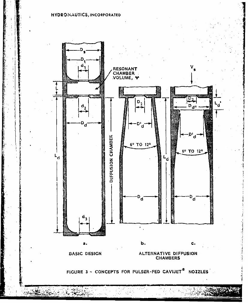
HYDRON AUTICS, INCORPORATED
RESONANTCHAMBER,
a.. .. . b. ..
DASI DESGN ATERNTIVEDIFISILdCHAMBER
FIGUE 3 CONEPTSFOR ULE-FEDCAVIET OZLES
_________D DO~ 4

H(DRONAUTI CS, INCORPORATED
VA
U VA.
TIME OR DISTANCE FROM ORIFICE
V +AV/2 V -AV,12
TIME NEEDED F-OR COMPLFTiE BUNCHING
T IAV
REQUIRED DISTANCE
po' k VX TV A
* ~FIGURE 4~ RELATIONS FOR COMPLETE BUNICHING

HYDRONAUTICS, INCORPORATED
1.4-
RELAXATION (lst CRITERION)
-0.85 CUSHIONING EFFECT (2nd CRITERION)
S0.8 OPTIMUM REGION
SAERODYNAMIC EFFECTS (3rd CRITERION)
0.6
0
o.2
0.05 0.1 1 10 100
MACH NUMBER, M
FIGURE 5 - CRITERIA FOR OPTIMIZING THE FREQUENCY OF PULSED JETS
I,1

HYDRO NAUTICS, INCORPORATED
PRESSURETRANSDUCER SERVOJET
FLASH BULB fjCAMERAA PHOTO
MULTIPLIER
PRESSURETRANS DUIC ER
OSCILLOSCOPE FREQ. ANALYSER
FIGURE 6 -EXPERIMENTAL SETUP

HYDRONAUTICS, INCORPORATED
UL
II
PULSER-FE-D AND ORGAN-PIPE
FIGURE 7 -SCHEMATIC OF SERVOJET NOZZLE9 CONSTRUCTEJ)
'IA,

HYDRONAUTICS, INCORPORATED
IuLU
I >*u
N It. u
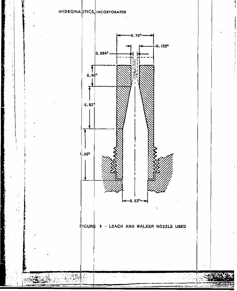
SHYDRONA JTICS, INCORPORATED
,e-*---0. 70" ------ WS 0"-0. 155
O. 084" .
I'
0.41I' ~I
* I
0.82'
1.00"1* 1
0.
* IGURI1 9 -'LEACH AND WALKER NOZZLE USED
'I TA W.
I:.,
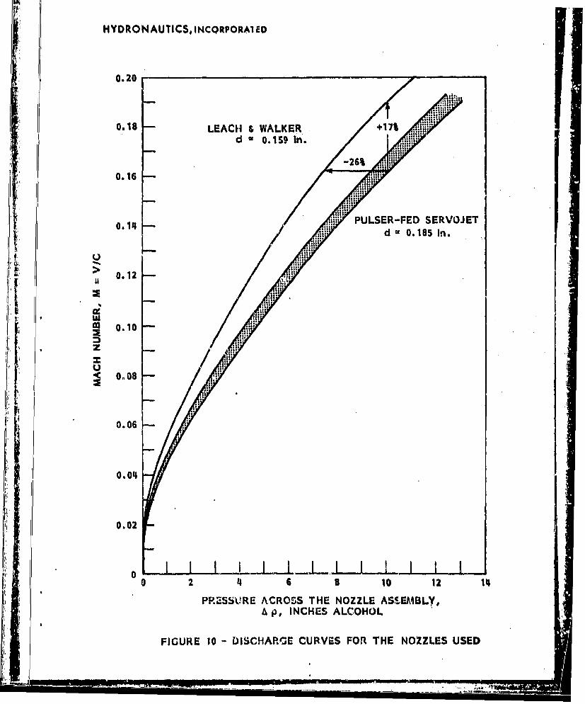
HYDRONAUTICS, INCQRPOtA1EID
0.20
0.18 LEACH &WALKER +17% :Upr
d U0.15S9 tn.MI
0.16
0.114 N ULSER-FED SERVOJET
> 0.12
0.10
me 00
0.06
0.04
0.*02
a2 4 6 8 10 12 114
PRESSU~RE ACROSS THE NOZZLE ASSEMBLY,A p, INCHES ALCOHOL
FIGURE 10 - DISCHAPr'sE CURVES FOR THE NOZZLES USED

HYDRONAUTICS, INCORPORATED
LZ 6PULSER-FED
U 1
0.
-3%
0.24
0.22 -LEACH & WALKERd =0.084 INCHES 6
0.20 ~-ORGAN-PIPE
SERVOJ ET
0.18 d 0. 1 INCH
0.16 PULSER-FFEDSERVOJETd 0. 1 INCH
c 0.14
j 0.12z
u 0.10
0.06
0.014
0.02
0 2 'I6810 12 114
PLV-U: CHOSS TI I NOZZLE ASSEMBLY, i p, I NCIIU-S ALCOH OL
~f(Tf.' 1 ~ArAiI;.2FCUJVFKS A\ND IF'RUSS(ME 0SCII-LA FIONS(I 01' THL NO.ZZLFS, (IS1.11)

HYDRONAUTICS, INCORPORATED
-•,: • ..,:,,
V<1 tsb. V 40 ft/s c. V 110 ftiB
FIGURE 12 - OSCILLATIO14 AND PRODUCTION OF~ DROPS IN RELATIVELYLOW VELOCITY JETS
-- ,-
I'I - F.F . ..... - .

HYORONAUTICS, INCORPORATED
__; • ':i' ' .. ,X = 14"
- I
T 4 1>1
a.NONEXCITED b. PULSAR-FEDfc4kl-z Sd'"0.13 164kHt; S 0.20V-~300 it/s1 pl/AP=O.7% Vc4256 ft/ v p'/APc02%
FIGURE 13 JET APPEARANCE AT A TOTAL PRESSURE DROP ACROSSTHE NOZZLE ASSEMBLY OV bAfl psi FOR A LEACH a WALKERNOZZLE SHAPE, d-.Ce.1155 INCH
rr
_ _-_,.,

HYDRciNAUTICS, INCORPORATEDia x iX 411'v ,v
I.1.
.b. c.
"4 NONXCIrTEO PULSAR FEDFw3kHz S z0. 11 F-3.BkHz, S&4.15
. V'365 ft/s, p'l/A o. 6% V,320 ft/s, p'IOI .9%
FIGURE 14 - 'ET APPEARANCE AT A TOTAL PRESSURE DROP ACROSSTHE NOZZLE ASSEMBLY OF 920 psi FOR A LEACH , WALKERNOZZLE SHAPE, d,,0.155 INCH
I-----•--- _ _ _- - "-
. . . ... . . . . .. . . . . . . . . . . . . . . . . . . . . . .

HlYDRONtAUTICS, INCORP1ORATED
I I
I. r.
it4
pm
, A , i
-- __--7%p/iP-79
a. V- 275 ft/s b. V•-296 ft/s c. Vw31O ft/spI/AP-7.7% p'W -P 7.9% pl/Ap •5.11%fs,-4.6 kHz f-L4.6 kHz f-4.5 kHz
FIGURE 15 - JET APPEARANCE IN THE MAXIMUM OSCILLATIONREGION. PULSAR-FED, d-0.185 INCHES, ,-0.02INCHES
-- --... -.... --- , - .. ---

'HYDRONAUl ICS, INCORPORATED
iJi
FIGURE 16 - JET APPEARANCE OF A PULSER-FED SERVOJET,Ap 810 pal, d * 0.10 In., f 3.6 kHz
LI

IIYDRONAUTICS, IICtORPOAIED
STROUflAL NUMBER, S d S
. tO
0 u
IL
PRMQUtNCY, t, kM.
FIGURE 17 - FREQUENCY SPECTRUM FOR A CAVIJET NONEXCITEDJET, 4 mw 0.165 Incheu, a -0.02 Inches, V ui 360 ft/a,
w 0.fl

IýYDRONAUTICS,INCORmPORATED
'STROUIIAL NUMBER, SdV
0.1 .0.2 0.I i .
.. . .. ~ -1`11
i 0m
I ~4 Iýt* 4 3-1lj .: .
FREQUHIENY 1.kM
FIUEZ RQEC PCRMFRAPLk-E AIENO0E .1 nhs .2IceVm30f/.
p'I~R 1 q5ff

HYDRONAUTICS, INCOEPORATUO
STROUHAL NUMBER, Sd d
•d •
I,,
0 .
TRANSDUCER
IPB, TRANSDUCERi: 2. ,1 3.1 4.1 5.1 6.1 *.1 1 .FREQUENCY, f. kHz
FIGURE 1- COMPARISON BETWEEN FREQUENCY SPECTRA OFPRESSURE OSCILLATION IN PIPE AND ON TARGETAT OPTIMUM STANDOFF DISTANCE, X047 INCHES,dm0.13! INCHES, eO.0R INCHES, Vw210 ftl/,(p'/&p)p 2-3.3%%, (p'/&P)tgrqet 2•13.,%
S . . . l IIII I I I II I I . : I

HYDROMAUTICS, INCO110ORATIO
STROUHAL NUMBER, Sd
0.20 03
.. . . . . . .
H... ......
. .. .. .......... . ...
FRE.UENCY .. ...
SPC.M .... 15 I.C.ES .... 5 .t ... &P....

HYDRONAUTICS, INCocPOmANID
STROUI4AL NUMBER,1 -
0 0.2 0.4 0.6 -0.8 1.0
X *15 inchvs, p'/Ap 2.9*%
0 .....
"it"4X JInc.pMp*22
#A ~X A 71 inches, pI/Ap 5.7%t
oIE 'p*25MRQNY 1A !R
TRNDCRA SVRLSADOFDSACSFIUEa. RSUR LCUTOSI PP N NTRE
V 1Lt., L..15Ice
0 -_ __ Ty- gi.:

STROUHAL NUMBER, fd/V,00.2 0.4
f tr
0~
........ .... X a 16 Inches, LASER
iX 10 Inches, LASER
E HilttPIPE, TRANSDUCER0.1 1.1 2.1 3.1 4.1 5.1 6.1 7.1 8.1
FREQUENCY', kHz
FIGURE. 22 - COMPARISON BETWEEN PRESSURE OSCILLATIONSIN PIPE SPECTRUM AND LIGHT INTERRUPTIONFLUCTUATIONS SPECTRA, V 296 ft/s., d 0.185Inches

* NYDRONAUTICS, INCORPc,'Ayw
MACHI NUMBER, M aVjc
*0.01 0.02 0.03 0.0% 0.05 0.04 0.07 0.030.5- I I IIII
0 0-R* a 4x 16 I " R e 31 5 x 10⁶ 1.20
3rd MOW) . .
Re. Vd',lv
04- 2nd MODES 0.40358
IIS
0.aK lot MODE~~~~ )rgnid MODE
0.111
I k0.105 lot M ODE -] 0.20
40100 200 300 400
*JET VELOCITY, V, (tim
10
4010 o.00.0
JEaEOCTV../
FIUE2 CUTCLC4AATRSISO UNR
FE CIoLd 015 NHS .3ICE
L .7IC E

I4YDRONAUTICS, INCORPOIATID
0.07
0.04 0.750 i
WI,
0.042
0.01 :, 01600
0.129
0.0O 0.08 0.12 0. 1 0.20 0.24 0.26
MACH NUMBER, - M V/i
IL 1.2
• 0.5
0o0.0 0.05 0.12 0.16 0.20 0.24 0.25
MACH NUMBER. M - Y Vi
FIGURE 24 - ACOUSTICAL ClsARACThRI'fICS OF A PULSER PEDSERVOJET, 0" 0..',, 1'dCHliS, d2 0.23 INCHES,
" 0,27 INCHES
Zing.

HYDOON.I.UTICS, INCOIPOWATIO
0.15 0.64
0.12 0.56
0.10 0.40
0.05 0.32
S, 0.
I I
oI I I I I I I I .+ I I I 10a 0.0o 0.08 0.12 0.16 0.20 0.24 0.26
S I-
"2.4
g~2.2
2.0 ,
1.°
1.6
0 1.62
12is 1.2
1.0
0.8
0.6
0.6
0.2
0 IJL L jI I I I I I I t0 0.0, 0.01 0.12 0.16 0.20 a. 21k 0.6
MACH NUMUER. M a Vic
FIGURE 25 - ACOUSTICAL CIIARACTERISTICS OF A PULSER-FrOSERVVOJET, d. . 0.10 MNCHES, d 1 4 0, INCHES,
A - 0.255 INCHES
S, .U- ..- ..* .. . -.... ........ -.. . .

HYDRONAUTICS, INCOR0O0ATEO
ORGAN PIPE e 0.08 INCHES6 ORGAN PIPE o = 0.13 INCHES
g. 0.6 ORGAN PIPE e - 0.20 INCHES, 0 LEACH 9 WALKER
f• o.s-
0.4* - '
z
0050.3-
S0.2-
0.1
,0 0.0o1 0.08 0,12 0.16 0.20 0.2I
MACH NUMBER, M R Vic
FIGURE 26 - PRESSURE OSCILLATIONS IN ORGAN-PIPE ANDLEACH AND WALKER NOZZLES TESTED
/7 T

HYDRONAUTICS, INCORPORATED
1 2 3 4 5
.:e
TRANSLATION STANDOFF NOZZLE
VELOCITY, X, In. PRESSURE,RUN In./s A _P, psi
f1 1.0 '4.0 5,2102 1.0 4.0 3,4203 1.5 14.0 5,22014 1.5 14.0 5,2205 1.5 54.5 5,100
4•
FIGURE 27 - NONUNIFORM PAINT.CLEANING IN REINFORCEDCARBON-FIBER PANELS. PANEL IA, PULSER-FEDSERVOJET
S. . . . . .• -r ... ..... .. . .. . . . . . . ..._

HYDIRONAUTICS, INCORPORATED
1 2 3 4 4a 3 7
NOZZLERUN NOZZUE TRANSLATION STANLOFF, PR&ESSUli,
TYPIE' VELOCITY, In. I/ X, In. p. Dai
] F I 1.0 4.7k, S,210I V I 1,0 .. 100S F 1.0 ,7, . 00OP I I O 24 0
I LW 1.0 10.25 5.aI ýrF1.0 --.75 0SL%, L 1.0 7.350
*PO': PULSER-FED befRVOJET; UF; ORGAN-PIPE SERVOJET;LW: LEACH t WALKER
.. PAPIEL WAS CUT THROUGH DUHING THIS RUN
FIGURE 29 - PAINT CLEANING IN REINFORCED CARBON-FIBER PANELS. PANEL 11B
- - -. , - -~ - - I.--

HYDRONAUTICS, INCORPORATUD
z U3
W-,
cn LL
I,-.L. C
_ I.lC3

HYDRONAUTICS, I'NCORPORATED
FIGURE 30 -PAINT REMOVAL PATHS AT A VARIABLE STANDOFF DISTANCE, 11 INCHES I X -- 23 INCHES,1D :LEACH £, WALKER, t p ' 5080 psi, 69 PULSER-FD -

HYDRO NA UTIC �, INC ORPO RATED
*1
*1
FIGURE 31 - PAINT REMOVAL PATHS AT THE OPTIMUM STANDOFF DISTANCE: X 14.5 INCHES. 8B PULSER-FLD
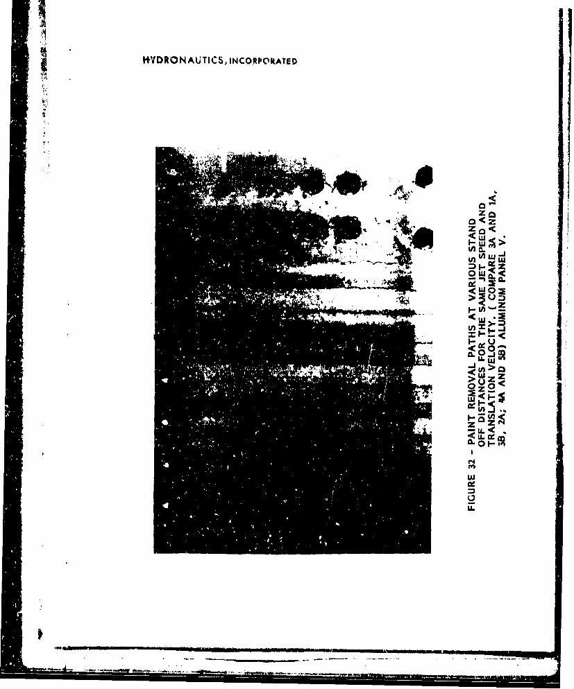
HYDRONAUTICS, INCO.RPOkATED
444
Z'
ti.Z
'.4< W
U- L
- - -Cie

HYDROt4AUTICS, INCORPORATED
SO
A PULSER-FED SERVOJET, d 0 0.084", Ap = 5400 psi
0 LEACH & WALKER, d 0.10". Ap S 5080 psi45
/
% h40j
35
TOP CAT
1..
3rd COAT _ •
s 3 - O T O
AV
o( .-25 .. [ "4r" - ... I
I-I
• , " • ' I'I T • : • •'":- -: - - " .. . .

HYDRONAUTICS, INCORPORATED
a.LEACH &WALKER
I.% fwv I
0.5 mm
b. PULSER-FED SERVOJET
FIGURE 34 - PHOTOMICROGRAPH OF THE PATHS FOR THE TWO'JETS AT THEIR OPTIMUM PERFORMANCE
----.---
7

HYDRONAUTICS, INCORPORATED
hLEACH & WALKER', Ap 8590 psi h': !11~u~ '
iiPULSER -FED, Ap 63!00 psi ~ ~ I 2~
FIGRE35 PESSREPRFIL AROS TEpJTll 1.5iNCE