Hydrolics and Pneumatics - Jordan University of Science...
43
Introduction to Hydraulics and Pneumatics
Transcript of Hydrolics and Pneumatics - Jordan University of Science...

Introduction to Hydraulics and Pneumatics

Principles of Hydraulics
§ The word “hydraulics” generally refers to power produced by moving liquids. Modern hydraulics is defined as the use of confined liquid to transmit power, multiply force, or produce motion.
§ Pascal: “Pressure applied on a confined fluid is transmitted in all directions with equal force on equal areas”.

Multiplication of Force
§ Since liquid transmit the same amount of pressure in all direc4ons. The force transmi7ed to the output piston is mul4plied by a factor equal to the area ra4o of the output piston to the input piston
Components of Hydraulic/Pneumatic Systems

Components of Hydraulic/Pneumatic Systems
1. Fluid: oil for hydraulic systems, air for pneumatics. 2. Reservoir: storage tank. 3. Hydraulic pump (compressor in pneumatics): converts the
mechanical energy into hydraulic energy by forcing fluid from the reservoir into the system.
4. Fluid lines: transport the fluid to and from the pump through the hydraulic system.
5. Valves: control pressure, direction and flow rate of the hydraulic fluid.
6. Actuator: converts hydraulic energy into mechanical energy to do work.

Applications

Example: lifting a load

Example: lifting a load

Example: lifting a load

Control valves
Control valves: are valves used to control conditions such as flow, pressure, and direction of flow.
§ Pressure control valves.
§ Flow control valves.
§ Directional control valves § Check Valves § Directional valves

Pressure Control Valves
A pressure control valve is used to reduce the amount of pressure in a tank or system
of pipes.

Pressure Control Valves

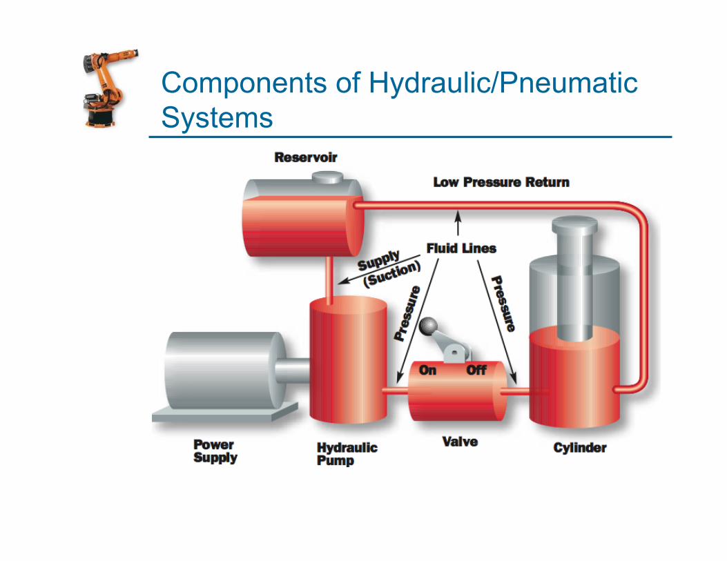
Flow Control Valves
Used to control fluid flow
Flow Control Valves
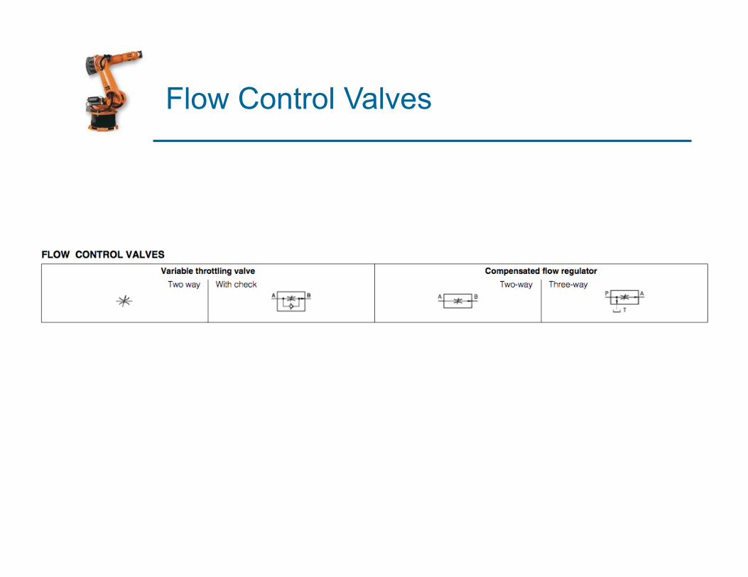
Directional control valves
§ Check Valves

Directional control valves
§ Directional valves

Directional valves

Example: Directional valves
The valve shown has 4 ports and 3 positions so it is designated as a 4/3
directional control valve.

Symbols
§ In hydraulics the pressure port is designated P and the return port R or T (for tank). The two other ports are designated A and B.
§ Boxes to identify normal and operating positions.
§ Arrows to identify flow directions.
§ In Pneumatics the pressure port is numbered (1) and the exhaust port (3). The other two are numbered (2) and (4).

Example: 4-ports 2-position directional control valve

Example: 4-ports 3-position directional control valve

Example: 4-ports 3-position directional control valve

Example: 5-ports 3-position directional control valve
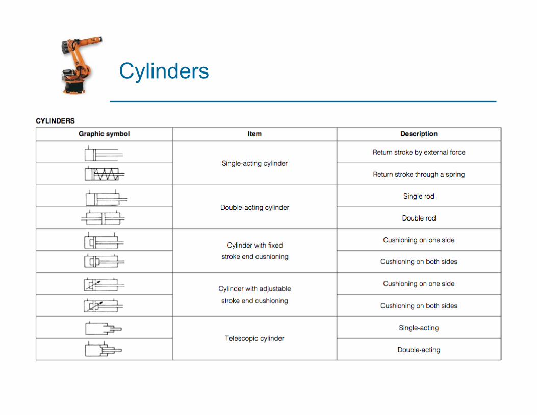
Cylinders

Pneumatic Circuits

Flow control valve (with check)
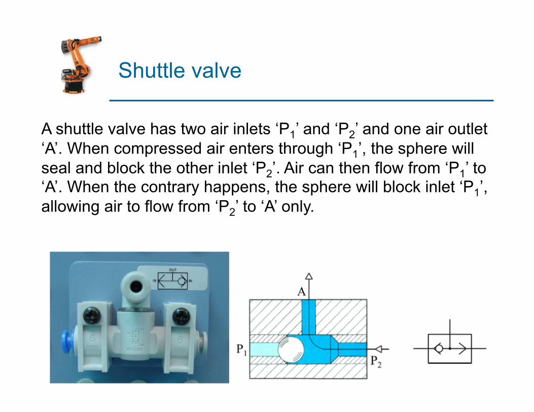
Shuttle valve
A shuttle valve has two air inlets ‘P1’ and ‘P2’ and one air outlet ‘A’. When compressed air enters through ‘P1’, the sphere will seal and block the other inlet ‘P2’. Air can then flow from ‘P1’ to ‘A’. When the contrary happens, the sphere will block inlet ‘P1’, allowing air to flow from ‘P2’ to ‘A’ only.
Pneumatic circuits
§ Pneumatic control systems can be designed in the form of pneumatic circuits. A pneumatic circuit is formed by various pneumatic components, such as cylinders, directional control valves, flow control valves, etc.
§ Pneumatic circuits have the following functions: 1. To control the injection and release of compressed air
in the cylinders. 2. To use one valve to control another valve.
§ Displayed as Pneumatic circuit diagram.

Example: Signal inversion
Pressure
Return
When valve in operation mode output is off

Example: Memory Function
When valve 1 is operated output is on until valve 2 is on then output is off.

Example: Delay function
ON-signal delay OFF-signal Delay

Example: Delay function cont.
Time delay valve

Example: Speed control

Example: OR Function

Example: AND Function

Example: NOT Function

Example: Double acting cylinder

Example: Transport system
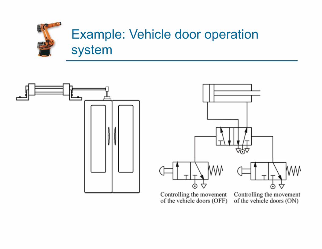
Example: Vehicle door operation system

Example: Plastic forming
When the push button is pressed, the 5/2 valve changes state and the cylinder outstrokes. As it outstrokes, it pushes the former together and the hot plastic sheet is pressed into shape. As this happens it also actuates the roller. Air now flows through the restrictor and starts to fill up the reservoir. Once the reservoir is full, the 5/2 valve changes state and the cylinder instrokes, ready for the process to begin again.

Example: full automatic circuit
As the piston instrokes, it trips valve A and the 5/2 valve changes state and the piston is sent positive. When it is fully outstroked, it trips valve B and the 5/2 valve returns to its original position, allowing the piston to instroke. The process begins all over again and continues to operate.

Example: Sequential control (furnace for heat treatment)
The sequence of operations for this process is as follows.
(a) An operator pushes a button to start the process.
(b) The furnace door is opened. (c) The block is pushed into the
furnace and the piston instrokes.
(d) The furnace door is closed. (e) The sequence stops.