
Hydrogen Fuel Cell Technology. FUEL CELL TECHNOLOGY Technology overview Hydrogen fuel development.

Hydrogen Storage Issues for Automotive Fuel Cells
JoAnn Milliken, U.S. Department of EnergyJohn Petrovic, Los Alamos National LaboratoryWalter Podolski, Argonne National Laboratory
International Workshop on Hydrogen in Materials and Vacuum Systems
11-13 November 2002Jefferson Lab
Newport News, Virginia

On-Board Hydrogen Storage Challenge
Storing enough hydrogen on vehicles to achieve greater than 300 miles driving range is difficult.
• On a weight basis H2 has nearly three times the energy content of gasoline.– 120 MJ/kg vs. 44 MJ/kg (LHV)
• On a volume basis the situation is reversed.– 3 MJ/L (5000 psi), 8 MJ/L (LH2) vs. 32 MJ/L
• Physical storage of hydrogen is bulky.• Capacity of reversible chemical storage at useful
T, P is low.• Other challenging issues include energy
efficiency, cost, and safety.

2010 DOE Technical Targets for On-Board Hydrogen Storage
TO BE REVISEDUnits Target
Storage Weight Percent % 6
Energy Efficiency % 97
Energy Density W-h/L 1100
Specific Energy W-h/kg 2000
Cost $/kW-h 5
Operating Temperature o -40–50oC
Start-Up Time To Full Flow sec 15
Hydrogen Loss scc/hr/L 1.0
Cycle Life Cycles 500
Recoverable Usable Amount % 90
Refueling Time min <5
DOE Hydrogen Storage Approaches
• Compressed and liquid hydrogen tanks• Chemical hydrides• Carbon structures• Complex metal hydrides
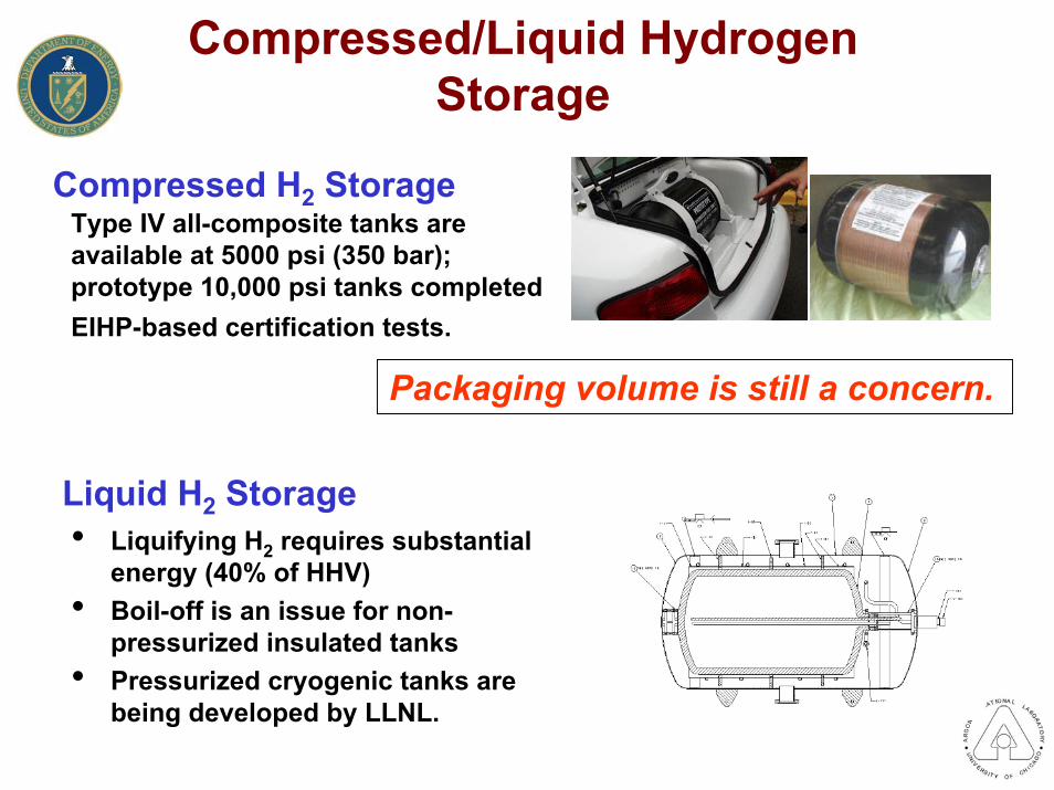
Compressed/Liquid Hydrogen Storage
Compressed H2 StorageType IV all-composite tanks are available at 5000 psi (350 bar); prototype 10,000 psi tanks completed EIHP-based certification tests.
Packaging volume is still a concern.
• Liquifying H2 requires substantial energy (40% of HHV)
• Boil-off is an issue for non-pressurized insulated tanks
• Pressurized cryogenic tanks are being developed by LLNL.
Liquid H2 Storage

Hydrogen Storage Workshop 14-15 August 2002
Argonne National LaboratoryThe focus of the workshop was on storage materials, with careful consideration of system level requirements.
• Identify and prioritize the most promising approaches to development of viable hydrogen storage materials/technologies
• Identify the technical challenges related to those approaches
• Draft a research and development plan to overcome those challenges

Overarching R&D Questions for All Advanced Materials
• Maximum storage capacity – theoretical model
• Energy balance / life cycle analysis
• Hydrogen absorption / desorption kinetics
• Preliminary cost analysis –potential for low cost, high volume
• Safety

Workshop Format
• Argonne National Laboratory– August 14-15, 2002– Attendees
• 49 DOE/Laboratory• 32 Industry• 16 University
– Plenary session• Overview of DOE Program• Automaker’s perspective• Four technology overview presentations
– Four breakout groups• Advanced/complex hydrides• Chemical storage• Carbon storage• Advanced concepts

General MotorsGravimetric Energy Density vs. Volumetric Energy Density
of Fuel Cell Hydrogen Storage Systems
0
5
10
15
20
25
30
35
40
0 5
Gra
vim
etric
Ene
rgy
Den
sity
M
J/kg LH2
SysWt% 4.2CGH2 SysWt% 3.7700bar
AdvancedLH2 TankSysWt% 8.2
HT+ MT- Metal HydridesSysWt% 3.3 - 3.4
LT- Metal Hydride SysWt% 1.2
DOE-Goal:SysWt%6.0
.
= Minimum Performance Goal
= Ultimate Technology Goal
10 15 20 25 30Volumetric Energy Density MJ/l
DOE target is too low.

Reversible Metal Hydride System
Fuel Cell
Hydride Storage
Recharging System
High press. H2
HeatRefrigerantHot water
Cool water
Aux. Heat
Sodium alanate doped with Ti is reversible but not quite suitable for vehicle applications.
3NaAlH4 ⇄ Na3AlH6 + 2Al + 3H2 ⇄ 3NaH + Al + 3/2H23.7 wt% 1.8 wt%
PEM fuel cell exhaust is near 80°C. Capacity and kinetics are too low.

Metal HydridesConclusions/Recommendations
• NaAlH4 capacity limited to about 5.6 wt%– Interim goal (5-year) of 6 wt%
• Need 8 wt% hydrogen material capacity if BOP adds 20%
Conclusions
• Continue fundamental studies on NaAlH4 as model system• Identify other hydride materials that have storage capacity
greater than 6 wt%• Develop new materials to achieve 8 wt% • Engineering analyses
– Preliminary system cost analysis– Large scale material production– Independent safety consultant/laboratory to understand
safety and certification issues
Recommendations

Chemical HydridesMillenium CellDaimlerChrysler
20 - 35% sol.Stabilized with
1-3% NaOHBorax in NaOHProprietary
catalyst
NaBH4 + 2H2O → NaBO2 + 4H2
2LiH + 2H2O→ 2LiOH + 2H2
Light mineral oil slurry, proprietary stabilizers
Pastebyproduct
ThermoPower
2Na + 2H2O→ 2NaOH + H2 Powerball
Polyethylene-coated pellets, mechanically cut to expose Na
Capacity is around 10 wt%, reduced by other materials.Dehydrogenation kinetics are fast.Reactions are irreversible on board vehicle.
Three Approaches

Chemical Hydride R&D Recommendations
• Screen chemical complexes– Hydrogen storage density potential– Thermodynamic energy requirements including regeneration
• Improved/new process chemistry– Catalysts– Operating conditions (temperature, pressure)
• Well-to-wheels-to-well analysis of top complexes– Primary energy use– Cost of delivered fuel– Emissions– Resource depletion

Single-Wall Carbon Nanotubes
• Capacity around 4 wt%• Doped SWNTs to 7 wt% by
NREL• Ambient temperature, moderate
pressure• SWNTs are made by arc
discharge, laser vaporization, CVD, and lithographically
• SWNTs must be purified, cut, and the ends opened
Reproducibility is a critical issue.
Wei, B. Q., et al, Nature, Vol. 416, April 2002

Carbon R&D Recommendations• Conduct definitive experiments to show where and how
hydrogen is stored in SWNT and for various forms of carbon– develop 2-3 pure SWNT standards for synthesis, purification,
activation, and hydrogen adsorption/desorption– conduct round-robin testing
• role of SWRI, other labs, universities, industry
• Better understand the science to engineer carbon for hydrogen storage
– Baseline theory to elucidate parameters affecting the number and type of binding sites and heat of reaction for a broad range of modified carbon materials
– Provide “directional” guidance for experiments (and vice-versa)

Advanced Concepts Identified
1. Crystalline Nanoporous Materials2. Polymer Microspheres
Self-Assembled Nanocomposites3. Advanced Hydrides4. Metals – Organic5. BN Nanotubes
Hydrogenated Amorphous Carbon6. Mesoporous materials7. Bulk Amorphous Materials (BAMs)8. Iron Hydrolysis9. Nanosize powders10. Metallic Hydrogen
Hydride Alcoholysis
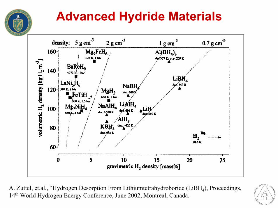
Advanced Hydride Materials
A. Zuttel, et.al., “Hydrogen Desorption From Lithiumtetrahydroboride (LiBH4), Proceedings, 14th World Hydrogen Energy Conference, June 2002, Montreal, Canada.
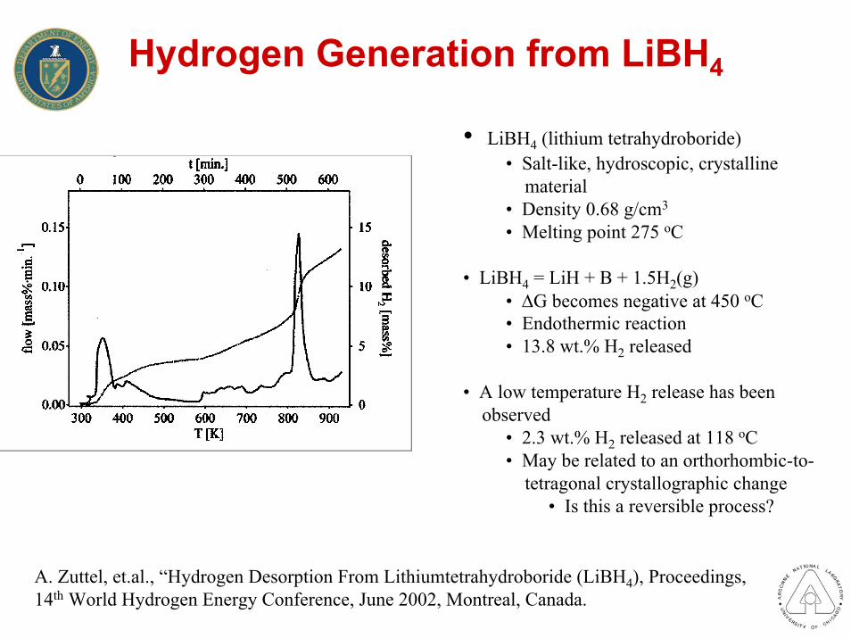
Hydrogen Generation from LiBH4
• LiBH4 (lithium tetrahydroboride)• Salt-like, hydroscopic, crystalline
material• Density 0.68 g/cm3
• Melting point 275 oC
• LiBH4 = LiH + B + 1.5H2(g)• ∆G becomes negative at 450 oC• Endothermic reaction• 13.8 wt.% H2 released
• A low temperature H2 release has beenobserved
• 2.3 wt.% H2 released at 118 oC• May be related to an orthorhombic-to-
tetragonal crystallographic change• Is this a reversible process?
A. Zuttel, et.al., “Hydrogen Desorption From Lithiumtetrahydroboride (LiBH4), Proceedings, 14th World Hydrogen Energy Conference, June 2002, Montreal, Canada.

Hydrolysis of LiBH4-OrganicsOrganics combined with LiBH4 to reduce the severity and heat of the hydrolysis reaction
M = lithiumL = organic ligand
Molecular weight of organicsin the range of 300 g/mol
2.5 wt.% H2 producedfrom Compound 1
R. Aiello, M.A. Matthews, D.L. Reger, and J.E. Collins, “Production of Hydrogen Gas From Novel ChemicalHydrides”, Int. J. Hydrogen Energy, 23, 1103-1108 (1998).

Chemical Reactions of Hydrides With Alcohols (Alcoholysis)
Controlled and convenient production of H2at room temperature and below
John Strom-Olsen, “Method of Hydrogen Generation for Fuel Cell Applications and a Hydrogen-Generating System”, Patent Filing WO0185606, May 2001, McGill University.

Hydrogen Adsorption by Boron Nitride Nanotubes
R. Ma, Y. Bando, H.Zhu, T. Sato, C. Xu, and D. Wu, “Hydrogen Uptake in Boron Nitride Nanotubes at Room Temperature”, J. Am. Chem. Soc., 124, 7672-7673 (2002).

Zeolite Structures
M.E. Davis, “Zeolites and Molecular Sieves: Not Just Ordinary Catalysts”, Ind. Eng. Chem. Res., 30, 1675-1683 (1991).

Comparison of Carbon and ZeoliteHydrogen Physisorption
• Physisorption at 77 oK and 1 bar pressure• Activated carbon Norit 990293
– BET surface area 2030 m2/gm– 2.1 wt.% hydrogen adsorbed
• Highest level of all carbon materials that were examined
• Zeolite ZSM-5– BET surface area 430 m2/gm– 0.7 wt.% hydrogen adsorbed
• Highest level of all silica-based materials that were examined
M.G. Nijkamp, J.E. Raaymakers, A.J. van Dillen, and K.P. de Jong, “Hydrogen Storage UsingPhysisorption – Materials Demands”, Appl. Phys. A, 72, 619-623 (2001).

Zeolite A
• {Na12[Al12Si12O48]}8• 8-ring channel• Three-dimensional
channels along <100>directions
• Channel diameter 0.42 nm
M.E. Davis, “Zeolites and Molecular Sieves: Not Just Ordinary Catalysts”, Ind. Eng. Chem. Res., 30, 1675-1683 (1991).

Hydrogen Storage In Zeolite A
• 0.05 wt.% H2 was reversibly stored in Zeolite A at 300 oC• H2 molecules believed to be stored in the sodalite cages
• Only 20-25% of sodalite cages contained an H2molecule• Reasons for this partial cage filling were unclear
• Can zeolites be chemically designed to store significantly more hydrogen?• H2 molecules stored in both sodalite and α cages
J. Weitkamp, M. Fritz, and S. Ernst, “Zeolites as Media for Hydrogen Storage”, International Journal of Hydrogen Energy, 20, 967-970 (1995).

Modeling of Hydrogen Storage in Zeolite A
Modeling suggests that Zeolite A can store at least 2 wt.% H2 if all cage sitesare filled
F. Darkrim, A. Aoufi, P. Malbrunot, and D. Levesque, “Hydrogen Adsorption in the NaA Zeolite: A Comparison Between Numerical Simulations and Experiments”, Journal of Chemical Physics, 112, 5991-5999 (2000).

Large Pore Zeolite UTD-1
• High silica zeolite– SiO2/Al2O3 ratio ~ 70
• 14-ring channel• One-dimensional
channel along [001]• Channel dimensions
of 1.0 x 0.75 nm
Hydrogen storage in large porezeolites has never been examined
R.F. Lobo, et.al., “Characterization of the Extra-Large-Pore Zeolite UTD-1”, J. Am. Chem. Soc., 119, 8474-8484 (1997).

Mesoporous MCM-41 Material
• Hexagonal array of uniformmesoporous channels rangingfrom 2-10 nm
J.S. Beck, et.al., “A New Family of Mesoporous Molecular Sieves Prepared With Liquid Crystal Templates”, J. Am. Chem. Soc., 114, 10834-10843 (1992).

Synthesis of Ordered Carbon Molecular Sieves by Templating
• Mesoporous silica molecular sieveMCM-48 impregnated withsucrose
• Sucrose converted to carbon by heating to 800-1100 oC in vacuum or inert atmosphere
• Silica framework dissolved in aqueous solution of NaOH and ethanol
R. Ryoo, S.H. Joo, and S. Jun, “Synthesis of Highly Ordered Carbon Molecular Sieves via Template-Mediated Structural Transformation”, J. Phys. Chem. B, 103, 7743-7746 (1999).

SiO2 Xerogels and Aerogels
• Xerogels• Produced by conventional drying
of wet silica gel• Aerogels
• Produced by liquid-to-gas dryingof wet silica gel
• Supercritical fluid drying
Structural Properties of SiO2 Aerogels
• Bulk density: 0.003-0.500 g/cm3
• Porosity: 80% - 99.8%• Mean pore diameter: 20-150 nm• BET surface area: 100-1600 m2/gm
N. Husing and U. Schubert, “Aerogels-Airy Materials: Chemistry, Structure, and Properties”,Angew. Chem. Int. Ed., 37, 22-45 (1998).

Porous Metal-Organic MOF-5
• Chemical formula Zn4O (BDC)3 (DMF)8 (C6H5Cl)• BCD = 1,4 - benzenedicarboxylate• DMF = dimethylformamide
• ZnO4 tetrahedral clusters linked together by C6H4-C-O2 “struts”• Cubic crystal structure• 1.294 nm spacing between centers of adjacent clusters
H. Li, M. Eddaoudi, M. O’Keeffe, O.M. Yaghi, “Design and Synthesis of an Exceptionally Stable and Highly Porous Metal-Organic Framework”, Nature, 402, 276-279 (1999).

Mesoporous Organosilica Material
benzene-silica hybrid material
S. Inagaki, S. Guan, T. Ohsuna, and O. Terasaki, “An Ordered Mesoporous Organosilica HybridMaterial With a Crystal-Like Wall Structure”, Nature, 416, 304-307 (2002).

Nanosize Metal and Ceramic Powders
• Nanosize metal and ceramic powders are commerciallyavailable• 10 - 100 nm diameters
• Nanosize metal powders• Au, Ag, Ni, Ti, Mo, Pt, W
• Nanosize ceramic powders• Al2O3, ZrO2, CeO2, CuO, MgO
SiO2, TiO2
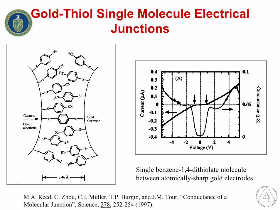
Gold-Thiol Single Molecule Electrical Junctions
Single benzene-1,4-dithiolate moleculebetween atomically-sharp gold electrodes
M.A. Reed, C. Zhou, C.J. Muller, T.P. Burgin, and J.M. Tour, “Conductance of a Molecular Junction”, Science, 278, 252-254 (1997).

Hydrogen Production by Grinding of Powders
• “In wet grinding in liquid media includingwater or alcohol, it has been confirmed that a considerable amount of hydrogen is generated and causes an abnormal increasein pressure of a closed mill pot, even when the feed materials hardly react with them.”
• Steel milling balls used to mill ceramic materials react with water to form hydrogen
• 3 Fe + 4 H2O = Fe3O4 + 4 H2• 3.3 wt.% H2 including
both Fe and H2O
T. Yokoyama, G. Jimbo, T. Nishimura, and S. Sakai, “Effect of Fineness of Wear Particles From Steel Balls on the Rate of Hydrogen Generation During Wet Grinding of Hard Materials in Water”, Powder Technology, 73, 43-49 (1992).

Hydrogen Storage in Modified Iron Oxides
• Additives accelerate reduction and oxidation reactions at lower temperatures• Al, Cr, Zr, Ga, V the most effective
H2 Storage: Fe3O4 + 4H2 = 3Fe + 4H2OH2 Recovery: 3Fe + 4H2O = Fe3O4 + 4H2
K. Otsuka, C. Yamada, T. Kaburagi, and S. Takenaka, “Storage and Generation of Pure Hydrogen by Utilization of Modified Iron Oxides”, Proceedings, 14th World Hydrogen Energy Conference, June 2002, Montreal, Canada.

Effects of Mechanical Milling on Hydrogen Storage in Graphite
• 200 µm graphite powder• Planetary milling with steel balls
and vial
S. Orimo, et.al., “Hydrogen in the MechanicallyPrepared Nanostructured Graphite”, Applied PhysicsLetters, 75, 3093-3095 (1999).
S. Orimo, et.al., “Hydrogen Desorption Property of Mechanically Prepared Nanostructured Graphite”, Journal of Applied Physics, 90, 1545-1549 (2001).
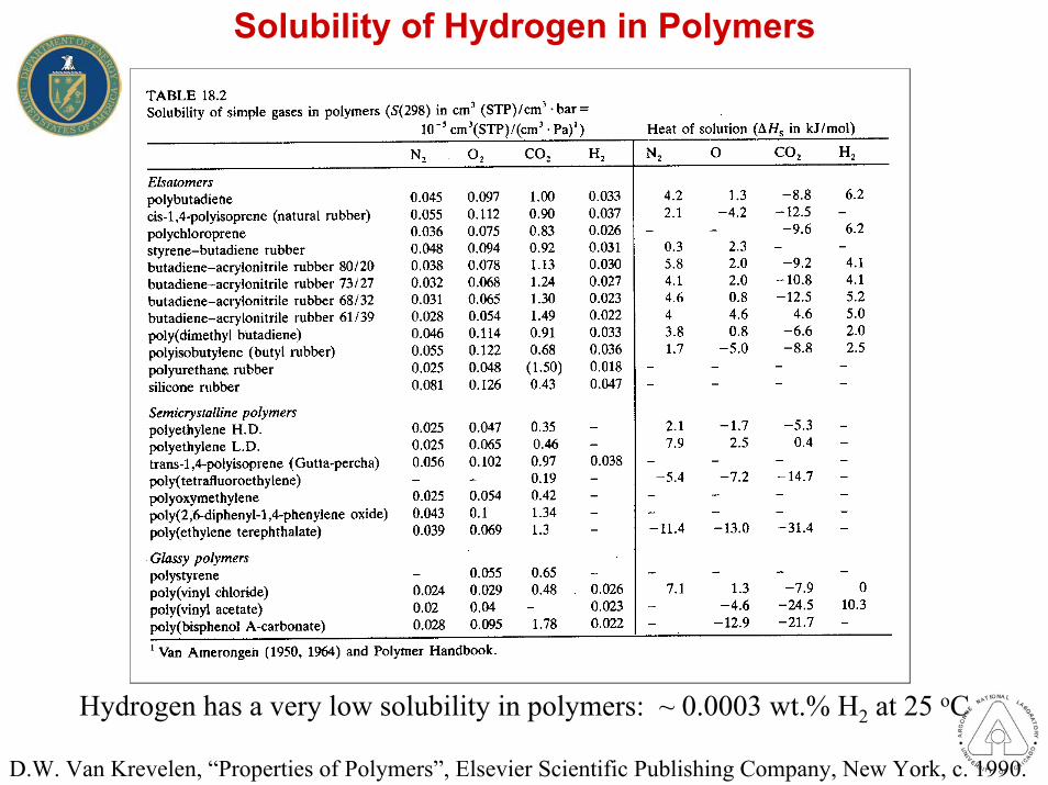
Solubility of Hydrogen in Polymers
Hydrogen has a very low solubility in polymers: ~ 0.0003 wt.% H2 at 25 oC
D.W. Van Krevelen, “Properties of Polymers”, Elsevier Scientific Publishing Company, New York, c. 1990.

Hydrogen Storage In Conducting Polymers
S.J. Cho, K.S. Song, J.W. Kim, T.H. Kim, and K. Choo, “Hydrogen Sorption in HCl-TreatedPolyanilineand Polypyrrole: New Potential Hydrogen Storage Media”, Fuel Chemistry Division Preprints, 47(1),
xxxx (2002).

Next Steps
• Prepare workshop proceedings• Hold workshop to address remaining R&D issues
for compressed hydrogen tanks• Update targets and draft 5-yr R&D Plan• Draft hydrogen storage solicitation• Accelerate development of standard test facility• Discuss advanced storage concepts further to
refine recommendations and resolve controversial aspects

For More Information
www.anl.gov/g8www.cartech.doe.gov/publications/2002hydrogenwww.eren.doe.gov/hydrogen/newswww.hydpark.ca.sandia.gov