
Hydrogen Fuel - Department of Energy hydrogen storage cylinders store the hydrogen fuel as a high...
32
Transcript of Hydrogen Fuel - Department of Energy hydrogen storage cylinders store the hydrogen fuel as a high...

Hydrogen Fuel Cell Engines
MODULE 5: FUEL CELL ENGINE SYSTEMS
Hydrogen Fuel Cell Engines and Related Technologies: Rev 0, December 2001
CONTENTS 5.1 INTRODUCTION...................................................................................................... 5-1 5.2 SYSTEM DESCRIPTIONS ......................................................................................... 5-2
5.2.1 AIR SYSTEM..................................................................................................... 5-2 5.2.2 FUEL STORAGE SYSTEM ................................................................................... 5-4 5.2.3 FUEL DELIVERY SYSTEM ................................................................................... 5-9 5.2.4 HUMIDIFICATION SYSTEM ................................................................................ 5-11 5.2.5 STACK COOLING SYSTEM................................................................................ 5-12 5.2.6 BUS COOLING SYSTEM ................................................................................... 5-14 5.2.7 HVAC SYSTEM .............................................................................................. 5-17 5.2.8 LUBRICATION SYSTEM..................................................................................... 5-18 5.2.9 HYDRAULIC SYSTEM ....................................................................................... 5-19 5.2.10 ELECTRICAL SYSTEM ...................................................................................... 5-20 5.2.11 CONTROL SYSTEM.......................................................................................... 5-23 5.2.12 LEAK DETECTION SYSTEM............................................................................... 5-24 5.2.13 FIRE SUPPRESSION SYSTEM............................................................................ 5-27
Hydrogen Fuel Cell Engines
MODULE 5: FUEL CELL ENGINE SYSTEMS
Hydrogen Fuel Cell Engines and Related Technologies: Rev 0, December 2001
OBJECTIVES At the completion of this module, the technician will understand:
• the systems required to operate a fuel cell engine
• the components and functionality of each fuel cell system

Hydrogen Fuel Cell Engines
MODULE 5: FUEL CELL ENGINE SYSTEMS
Hydrogen Fuel Cell Engines and Related Technologies: Rev 0, December 2001
PAGE 5-1
Key Points & Notes 5.1 Introduction A fuel cell stack requires fuel, oxidant and coolant in order to operate. The composition, pressure and flow rate of each of these streams must be regulated. In addition, the gases must be humidified and the coolant temperature must be controlled. To achieve this, the fuel cell stack must be sur-rounded by a fuel system, fuel delivery system, air system, stack cooling system and humidification system.
Once operating, the output power generated by the fuel cells must be conditioned and absorbed by a load. Suitable alarms must shut down the process if unsafe operating conditions occur and a cell voltage monitoring system must monitor fuel cell stack performance. These functions are performed by electrical and control systems.
When a fuel cell powerplant is installed in a transit bus, it must interface with the power train, steering circuit, bus cooling system and HVAC system. The power train includes the drive motor, transmission and ancillary components. The steering circuit uses pressurized hydraulic oil to operate the steering mechanism. The bus cooling system removes heat from standard bus and fuel cell components, supplies heat to the HVAC system, and rejects waste heat to the environ-ment. The HVAC system provides coach heat and air condi-tioning. This equipment requires subsidiary lubrication and hydraulic systems in order to operate.
In addition, the presence of hydrogen on-board a bus re-quires additional equipment to ensure passenger safety. This takes the form of a leak detection system to detect escaped hydrogen and a fire suppression system to detect and extin-guish fires.

Hydrogen Fuel Cell Engines
MODULE 5: FUEL CELL ENGINE SYSTEMS
Hydrogen Fuel Cell Engines and Related Technologies: Rev 0, December 2001
PAGE 5-2
Key Points & Notes 5.2 System Descriptions The following system descriptions pertain to a bus applica-tion using pure hydrogen stored as a high pressure gas. These descriptions are based on the Phase 3 and 4 fuel cell buses designed and built by XCELLSiS Fuel Cell Engines, Inc. This information represents the most complete descrip-tion currently available, although it cannot cover all hard-ware configurations and variations.
These system descriptions indicate the basic functionality of each system, the type of components required, and their interrelationships. Specific fuel cell buses differ from these descriptions in a variety of details depending on the state of the art at the time of manufacture, constraints imposed by the specific bus chassis, and the level of component integra-tion.
For the purpose of clarity, transducers, switches and other incidental components are not included in the descriptions.
5.2.1 Air System
The air system supplies regulated air to the fuel cells to feed the power generation reaction.
Ambient air enters the air system and passes through a particulate filter to remove debris from the air and a silencer to muffle the downstream compressor noise.
The air is compressed in two stages using a air compressor and a turbocharger. The speed of the air compressor both increases the air pressure and sets the air flow rate. The turbocharger further increases the pressure by recovering energy from the exhaust air stream. Under normal operating conditions, the air pressure entering the fuel cell stacks is nominally 30 psig (2 barg).
Air pressurization greatly increases the temperature of the air stream and may introduce oil particles (a fuel cell poison) from the interaction of the lubrication system with the com-pressors. To prevent damage to the fuel cells, the hot air stream passes through an intercooler after the air compres-sor to cool it to the fuel cell operating temperature. The heat is transferred to the bus cooling system.
The cooled air destined for the fuel cell stacks flows through an inlet filter to remove any oil contaminants and a mass flow meter to measure the actual air flow. The air stream then passes through a humidifier, where it is saturated with

Hydrogen Fuel Cell Engines
MODULE 5: FUEL CELL ENGINE SYSTEMS
Hydrogen Fuel Cell Engines and Related Technologies: Rev 0, December 2001
PAGE 5-3
Key Points & Notes water at the stack operating temperature, and enters the fuel cell stacks where it feeds the power generation reaction.
The depleted hot air that exits the fuel cell stacks contains water as a product of the power generation reaction and from humidification. This water is primarily in the vapor state and is largely recovered by passing the air through a condenser and a coalescing air/water separator. The con-denser transfers heat to the bus cooling system. Both the condenser and separator pass recovered water to the hu-midification water tank. Some air flows into the header tank along with the water; this provides positive ventilation of the tank while maintaining a pressure balance between the air and water systems.
Downstream of the water separator, the air turns the turbo-charger turbine, passes through a second silencer, and vents to the atmosphere.
Figure 5-1 Air System Flow Diagram
Hydrogen Fuel Cell Engines
MODULE 5: FUEL CELL ENGINE SYSTEMS
Hydrogen Fuel Cell Engines and Related Technologies: Rev 0, December 2001
PAGE 5-4
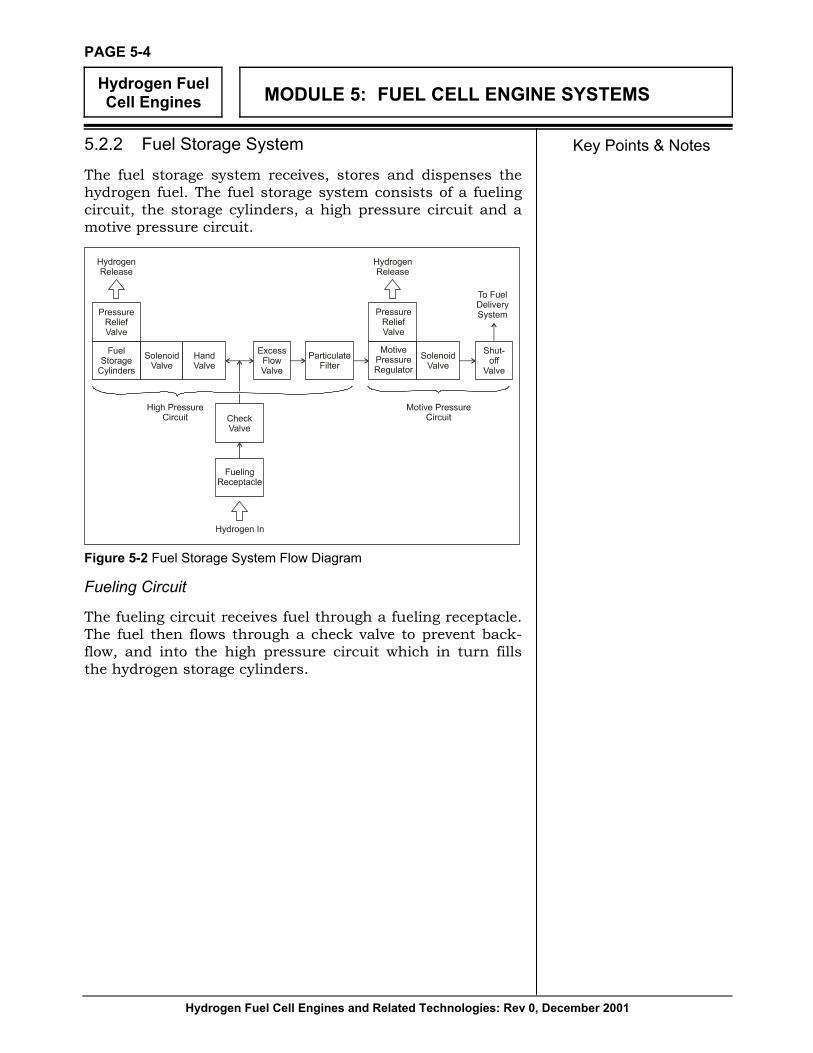
Key Points & Notes 5.2.2 Fuel Storage System
The fuel storage system receives, stores and dispenses the hydrogen fuel. The fuel storage system consists of a fueling circuit, the storage cylinders, a high pressure circuit and a motive pressure circuit.
Figure 5-2 Fuel Storage System Flow Diagram
Fueling Circuit
The fueling circuit receives fuel through a fueling receptacle. The fuel then flows through a check valve to prevent back-flow, and into the high pressure circuit which in turn fills the hydrogen storage cylinders.

Hydrogen Fuel Cell Engines
MODULE 5: FUEL CELL ENGINE SYSTEMS
Hydrogen Fuel Cell Engines and Related Technologies: Rev 0, December 2001
PAGE 5-5
Key Points & Notes Hydrogen Storage Cylinders
The hydrogen storage cylinders store the hydrogen fuel as a high pressure gas for consumption by the engine.
Figure 5-3 Typical Fuel Storage System Layout
Figure 5-4 Hydrogen Storage Cylinders

Hydrogen Fuel Cell Engines
MODULE 5: FUEL CELL ENGINE SYSTEMS
Hydrogen Fuel Cell Engines and Related Technologies: Rev 0, December 2001
PAGE 5-6
Key Points & Notes The end boss through which the fuel flows into and out of each cylinder includes an integral solenoid valve, check valve, excess flow valve and shutoff valve assembly (or “manual lockdown assembly”).
The solenoid valve automatically closes and isolates the cylinder whenever the bus is off. The check valve permits fueling while the solenoid valve is closed.
The excess flow valve interrupts the fuel flow out of the cyl-inder whenever the flow rate is excessive (such as if a pipe bursts or during vigorous venting). When closed, the excess flow valve permits a small amount of leakage so that the outlet and cylinder pressures equalize over a period of time, thereby restoring normal valve function.
The manual lockdown assembly can be used to isolate the cylinder contents, but is normally left fully open. In the event that a solenoid valve fails closed, the manual lockdown assembly can be removed and replaced with a venting tool that forces the solenoid valve open in order to discharge the cylinder contents.
An external hand valve is typically installed in the inlet pipe associated with each cylinder. This valve provides an addi-tional level of safety (in addition to the integral solenoid valve) and is a convenient method of isolating individual cylinders during fueling or venting.
Pressure relief devices are attached to the end bosses at both ends of each cylinder and protect against explosion in the event of a fire. Each pressure relief device is in contact with the internal gas pressure and contains a eutectic compound that acts as a plug. When exposed to fire, the eutectic com-pound melts and the internal gas escapes through a vent line that passes through the roof canopy.

Hydrogen Fuel Cell Engines
MODULE 5: FUEL CELL ENGINE SYSTEMS
Hydrogen Fuel Cell Engines and Related Technologies: Rev 0, December 2001
PAGE 5-7
Key Points & Notes
Figure 5-5 Pressure Relief Devices
High Pressure Circuit
The high pressure circuit consists of a common manifold that links the hydrogen storage cylinders with both the fuel-ing circuit and the motive pressure circuit.
During operation, high pressure hydrogen passes from the cylinders into the high pressure circuit where it flows though an excess flow valve to the motive pressure regulator assem-bly. The excess flow valve closes if excessive flow occurs, providing redundancy to the excess flow valves integrated into each cylinder end boss.
The high pressure circuit includes a hand-operated vent valve, mounted on the common manifold, used when venting and purging the high pressure circuit during maintenance.
Motive Pressure Circuit
The motive pressure circuit supplies intermediate pressure hydrogen to the fuel delivery system.
The motive pressure circuit consists of a pressure regulator assembly, a filter, and a fuel shutoff valve the fuel delivery tube to the engine. The pressure regulator assembly is an integral unit that includes a pressure regulator, a solenoid valve and a pressure relief valve.
Hydrogen Fuel Cell Engines
MODULE 5: FUEL CELL ENGINE SYSTEMS
Hydrogen Fuel Cell Engines and Related Technologies: Rev 0, December 2001
PAGE 5-8
Key Points & Notes
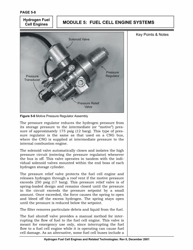
Figure 5-6 Motive Pressure Regulator Assembly
The pressure regulator reduces the hydrogen pressure from its storage pressure to the intermediate (or “motive”) pres-sure of approximately 175 psig (12 barg). This type of pres-sure regulator is the same as that used on a CNG bus, where the CNG is supplied at intermediate pressure to the internal combustion engine.
The solenoid valve automatically closes and isolates the high pressure circuit (entering the pressure regulator) whenever the bus is off. This valve operates in tandem with the indi-vidual solenoid valves mounted within the end boss of each hydrogen storage cylinder.
The pressure relief valve protects the fuel cell engine and releases hydrogen through a roof vent if the motive pressure exceeds 250 psig (17 barg). This pressure relief valve is of spring-loaded design and remains closed until the pressure in the circuit exceeds the pressure setpoint by a small amount. Once exceeded, the force causes the spring to open and bleed off the excess hydrogen. The spring stays open until the pressure is reduced below the setpoint.
The filter removes particulate debris and liquid from the fuel.
The fuel shutoff valve provides a manual method for inter-rupting the flow of fuel to the fuel cell engine. This valve is meant for emergency use only, since interrupting the fuel flow to a fuel cell engine while it is operating can cause fuel cell damage. As an alternative, some fuel cell buses include a
Hydrogen Fuel Cell Engines
MODULE 5: FUEL CELL ENGINE SYSTEMS
Hydrogen Fuel Cell Engines and Related Technologies: Rev 0, December 2001
PAGE 5-9
Key Points & Notes fuel shutoff valve that is electrical rather than mechanical in nature. When actuated, this valve immediately shuts down the engine in a controlled manner and closes the cylinder and pressure regulator assembly solenoid valves.
5.2.3 Fuel Delivery System
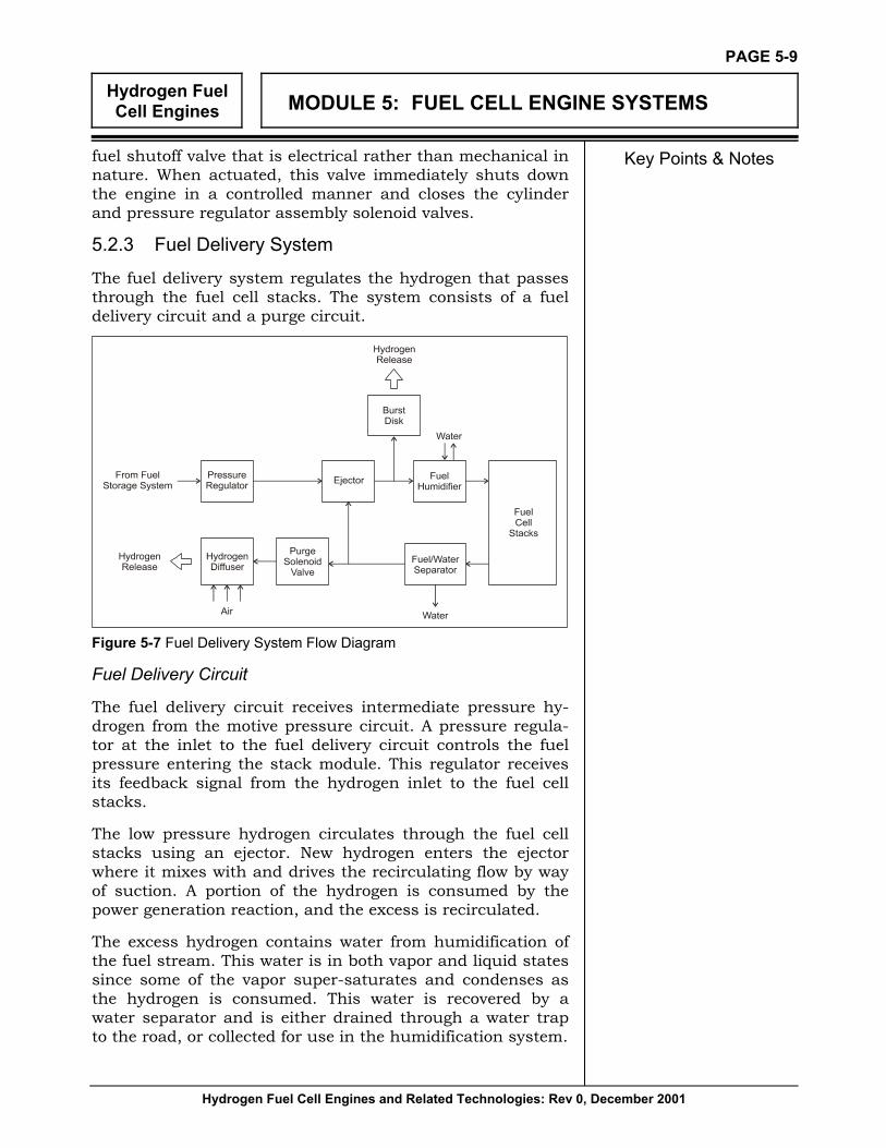
The fuel delivery system regulates the hydrogen that passes through the fuel cell stacks. The system consists of a fuel delivery circuit and a purge circuit.
Figure 5-7 Fuel Delivery System Flow Diagram
Fuel Delivery Circuit
The fuel delivery circuit receives intermediate pressure hy-drogen from the motive pressure circuit. A pressure regula-tor at the inlet to the fuel delivery circuit controls the fuel pressure entering the stack module. This regulator receives its feedback signal from the hydrogen inlet to the fuel cell stacks.
The low pressure hydrogen circulates through the fuel cell stacks using an ejector. New hydrogen enters the ejector where it mixes with and drives the recirculating flow by way of suction. A portion of the hydrogen is consumed by the power generation reaction, and the excess is recirculated.
The excess hydrogen contains water from humidification of the fuel stream. This water is in both vapor and liquid states since some of the vapor super-saturates and condenses as the hydrogen is consumed. This water is recovered by a water separator and is either drained through a water trap to the road, or collected for use in the humidification system.
Hydrogen Fuel Cell Engines
MODULE 5: FUEL CELL ENGINE SYSTEMS
Hydrogen Fuel Cell Engines and Related Technologies: Rev 0, December 2001
PAGE 5-10
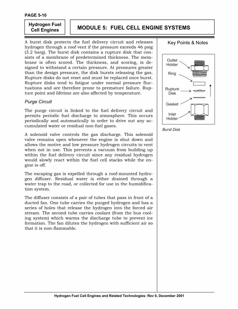
Key Points & Notes A burst disk protects the fuel delivery circuit and releases hydrogen through a roof vent if the pressure exceeds 46 psig (3.2 barg). The burst disk contains a rupture disk that con-sists of a membrane of predetermined thickness. The mem-brane is often scored. The thickness, and scoring, is de-signed to withstand a certain pressure. At pressures greater than the design pressure, the disk bursts releasing the gas. Rupture disks do not reset and must be replaced once burst. Rupture disks tend to fatigue under normal pressure fluc-tuations and are therefore prone to premature failure. Rup-ture point and lifetime are also affected by temperature.
Purge Circuit
The purge circuit is linked to the fuel delivery circuit and permits periodic fuel discharge to atmosphere. This occurs periodically and automatically in order to drive out any ac-cumulated water or residual non-fuel gases.
A solenoid valve controls the gas discharge. This solenoid valve remains open whenever the engine is shut down and allows the motive and low pressure hydrogen circuits to vent when not in use. This prevents a vacuum from building up within the fuel delivery circuit since any residual hydrogen would slowly react within the fuel cell stacks while the en-gine is off.
The escaping gas is expelled through a roof-mounted hydro-gen diffuser. Residual water is either drained through a water trap to the road, or collected for use in the humidifica-tion system.
The diffuser consists of a pair of tubes that pass in front of a ducted fan. One tube carries the purged hydrogen and has a series of holes that release the hydrogen into the forced air stream. The second tube carries coolant (from the bus cool-ing system) which warms the discharge tube to prevent ice formation. The fan dilutes the hydrogen with sufficient air so that it is non-flammable.

Hydrogen Fuel Cell Engines
MODULE 5: FUEL CELL ENGINE SYSTEMS
Hydrogen Fuel Cell Engines and Related Technologies: Rev 0, December 2001
PAGE 5-11
Key Points & Notes 5.2.4 Humidification System
The humidification system saturates the hydrogen and air with water prior to their use in the fuel cells, and manages the product water that results from the fuel cell reaction.
Figure 5-8 Humidification System Flow Diagram
Humidification
Some fuel cell powerplants combine the humidification sys-tem with the stack cooling system. This results in a simple, well integrated system with excellent temperature matching characteristics. However, this arrangement precludes the use of anything other than pure water as stack coolant, which exacerbates cold weather starting problems (since the cooling water freezes).
The humidification system consists of a single circuit that draws humidification water from a product water tank, using a pump, and passes the water through a particulate filter and a de-ionizing filter. The particulate filter removes par-ticulate debris from the water. The de-ionizing filter contains a mixed-bed resin to remove anions and cations.
Ions cause fluid conductivity and accumulate during normal operation. Conductivity within any fluid stream that passes through the fuel cell stacks can cause short circuits within the fuel cells. This results in corrosion currents that lower performance and can cause fuel cell damage.

Hydrogen Fuel Cell Engines
MODULE 5: FUEL CELL ENGINE SYSTEMS
Hydrogen Fuel Cell Engines and Related Technologies: Rev 0, December 2001
PAGE 5-12
Key Points & Notes The water leaving the de-ionizing filter splits into two streams; one stream is used for fuel humidification and the other for air humidification. Each stream flows through a check valve and into a humidifier. Some of the water passes into the gas stream and the remainder collects in a reservoir within the humidifier. This excess water passes through a drain valve back into the product water tank.
Source heat for the humidifiers is drawn from the stack coolant. This ensures that both the fuel cells and the hu-midifier operate at the same temperature so that the maxi-mum amount of water vapor can be carried into the fuel cells. This heat can be used directly, by using the same water in both the stack cooling and humidification circuits, or indirectly by transferring the heat from the stack coolant to the humidification water using a heat exchanger.
5.2.5 Stack Cooling System
The stack cooling system regulates the fuel cell reaction temperature, provides source heat to humidify the reactant gases, serves as a heat sink for an electrical resistor and provides source heat for the HVAC system.
The stack cooling system consists of a main coolant loop and a bypass filtration loop.
Figure 5-9 Stack Cooling System Flow Diagram

Hydrogen Fuel Cell Engines
MODULE 5: FUEL CELL ENGINE SYSTEMS
Hydrogen Fuel Cell Engines and Related Technologies: Rev 0, December 2001
PAGE 5-13
Key Points & Notes Main Coolant Loop
The main coolant loop circulates the stack coolant through the fuel cell stacks where it absorbs heat and maintains the fuel cells at their optimum operating temperature. As the coolant leaves the stacks, it flows through the air and hydro-gen humidifiers where it supplies the heat required to vapor-ize the humidification water. The coolant then enters the dump chopper.
The dump chopper consists of a chamber through which the stack coolant flows and into which is suspended a resistor. The resistor transfers heat to the stack cooling system both during initial startup, to quickly raise the coolant and thereby the fuel cells to their operating temperature, and whenever the bus is off, to deplete residual reactants from the fuel cell stacks.
Coolant leaving the dump chopper passes through a heat exchanger that transfers heat to the heating/air conditioning circuit as required.
A motor operated control valve then splits the coolant flow into two streams. One stream passes through the main heat exchanger (which transfers heat to the bus cooling system) and the second stream bypasses it. The two streams re-mix after the heat exchanger with a resulting final temperature that depends on the relative flow within each path.
Coolant leaving the main heat exchanger enters a pump and passes back into the fuel cell stacks.
Additional coolant is fed into the main coolant loop from a header tank as required.
Bypass Filtration Loop
As with the humidification water, the stack coolant must be non-conductive in order to prevent internal short circuits as it passes through the fuel cells. The stack coolant can there-fore be either pure de-ionized water, or a mixture of 50% pure de-ionized water with 50% pure ethylene glycol (the glycol must be free of additives that could damage the fuel cells).
When pure water is used, the stack cooling system can be merged with the humidification system reducing overall complexity (since the stack cooling water can be used di-rectly to humidify the reactant gases). However, the use of water complicates cold weather operation since it freezes at 32 ºF (0 ºC). Conversely, using a water/glycol mixture im-

Hydrogen Fuel Cell Engines
MODULE 5: FUEL CELL ENGINE SYSTEMS
Hydrogen Fuel Cell Engines and Related Technologies: Rev 0, December 2001
PAGE 5-14
Key Points & Notes proves cold weather performance but necessitates the use of a separate humidification system.
Regardless of the coolant composition, it must remain non-conductive just like the humidification water. This is accom-plished by diverting a portion of the stack coolant flow through a bypass filtration loop that includes a de-ionizing filter.
Coolant for the bypass filtration loop is drawn from the main coolant loop at the pump outlet. The coolant passes in suc-cession through a heat exchanger, a strainer, the de-ionizing filter, a second strainer and a solenoid valve before re-joining the main coolant loop at the inlet to the dump chopper.
The de-ionizing filter contains a mixed-bed resin to remove anions and cations. The heat exchanger reduces the filtra-tion coolant temperature in order to protect the de-ionizing filter resin, transferring the heat to the bus cooling system. The strainers remove particulate debris from before and after the filter assembly to protect the fuel cell stacks from es-caped filter resin or other particulate matter. The solenoid valve controls the coolant flow through the filter loop.
5.2.6 Bus Cooling System
The bus cooling system absorbs heat from various systems associated with the fuel cell engine and expels excess heat to the atmosphere.

Hydrogen Fuel Cell Engines
MODULE 5: FUEL CELL ENGINE SYSTEMS
Hydrogen Fuel Cell Engines and Related Technologies: Rev 0, December 2001
PAGE 5-15
Key Points & Notes
Figure 5-10 Bus Cooling System Flow Diagram
Hydrogen Fuel Cell Engines
MODULE 5: FUEL CELL ENGINE SYSTEMS
Hydrogen Fuel Cell Engines and Related Technologies: Rev 0, December 2001
PAGE 5-16
Key Points & Notes The bus cooling system circulates coolant, using a pump, through the following components:
• inverter
• condenser
• intercooler
• bus chassis air compressor
• main heat exchanger
• de-ionizing filter heat exchanger
• lubrication oil cooler
• transmission fluid cooler
The coolant absorbs heat from each component except the hydrogen diffuser, which it heats in order to prevent ice formation. The manner in which the individual components are plumbed together (whether in parallel or series) depends on the nature of each cooling load and the physical location of each component within the bus chassis. Some compo-nents, such as the condenser, may include a solenoid valve or other flow control device to regulate the amount of coolant flow.
After passing through the various components, the bus coolant streams merge and flow through a filter to remove particulate debris. A temperature controlled bypass valve then splits the coolant flow, causing some to flow through a radiator and some to bypass it. The two streams re-mix after the radiator with a resulting final temperature that depends on the relative flow within each path. The radiator expels the heat to the atmosphere using fans driven by the hydraulic system.
Additional coolant is fed into the coolant circuit from a header tank as required.
Since the bus coolant does not come into direct contact with the fuel cells, it does not need to be de-ionized and consists of a standard solution of 50% ethylene glycol with 50% clean water.

Hydrogen Fuel Cell Engines
MODULE 5: FUEL CELL ENGINE SYSTEMS
Hydrogen Fuel Cell Engines and Related Technologies: Rev 0, December 2001
PAGE 5-17
Key Points & Notes 5.2.7 HVAC System
The HVAC system provides source heat to warm the passen-ger compartment.
Figure 5-11 HVAC System Flow Diagram
Source heat for the HVAC system is drawn from the stack coolant stream by way of the HVAC heat exchanger. A by-pass solenoid valve is used to regulate whether the HVAC coolant flows through the heat exchanger or around it de-pending on the heating demand. The hot coolant then flows through a heater, which adds additional electrical heat if required, and passes into the coach heater, which distrib-utes the heat throughout the passenger compartment. The coolant then flows back to the booster pump and the circula-tion repeats.
Additional coolant is fed into the HVAC circuit from a header tank as required.
Since the HVAC coolant does not come into direct contact with the fuel cells, it does not need to be de-ionized and consists of a standard solution of 50% ethylene glycol with 50% clean water.

Hydrogen Fuel Cell Engines
MODULE 5: FUEL CELL ENGINE SYSTEMS
Hydrogen Fuel Cell Engines and Related Technologies: Rev 0, December 2001
PAGE 5-18
Key Points & Notes 5.2.8 Lubrication System
The lubrication system provides lubrication and cooling to key rotating components.
Figure 5-12 Lubrication System Flow Diagram
Lubrication oil resides within the sump of the drive motor. A pump, located within the sump, forces the oil through a particulate filter and into a distribution manifold. The mani-fold first directs the oil through the lubrication oil cooler, where it expels heat to the bus cooling system, and then distributes the oil flow through the following components:
• bus chassis air compressor
• turbocharger
• air compressor
• gearcase (used to drive ancillary components)
• drive motor
• alternator The manner in which the individual components are plumbed together (whether in parallel or series) depends on the nature of each lubricating load and the physical location of each component within the bus chassis.
The lubrication system uses synthetic oil with a low vapor pressure in order to minimize the amount of oil that diffuses into the air stream within the air compressor and turbo-charger. This decreases the risk of fuel cell contamination.

Hydrogen Fuel Cell Engines
MODULE 5: FUEL CELL ENGINE SYSTEMS
Hydrogen Fuel Cell Engines and Related Technologies: Rev 0, December 2001
PAGE 5-19
Key Points & Notes 5.2.9 Hydraulic System
The hydraulic system powers the radiator fans and power steering system. The hydraulic system consists of a radiator fan circuit and a power steering circuit.
Figure 5-13 Hydraulic System Flow Diagram
Radiator Fan Circuit
The radiator fan circuit draws hydraulic fluid from a tank using a variable speed pump. The fluid then splits into three streams. Two of the streams pass directly through respective radiator fan motors. The third stream flows to a pressure relief valve. The pump speed, and therefore fan speeds, var-ies according to heat rejection requirements.
Each of the two radiator fan motors is connected to a fan that draws air through the radiator in order to expel heat from the bus cooling system to atmosphere.

Hydrogen Fuel Cell Engines
MODULE 5: FUEL CELL ENGINE SYSTEMS
Hydrogen Fuel Cell Engines and Related Technologies: Rev 0, December 2001
PAGE 5-20
Key Points & Notes The pressure relief valve protects the variable speed pump from damage by providing a flow path should the fan motors offer too great a flow resistance.
A check valve links the motor outlets to inlets and acts as a pressure relief during system shutdown.
The hydraulic streams re-combine after the fan motors and flow through a fluid cooler and a filter before returning to the tank. The fluid cooler is exposed to the air stream that flows through the radiator and expels waste heat to atmosphere. The filter removes particulate debris from the fluid.
Figure 5-14 Radiator Fan Assembly Components
Power Steering Circuit
The power steering circuit draws hydraulic fluid from a tank using a pump. In some systems this tank is the same as that used in the radiator fan circuit; in others, a separate tank is used. The fluid leaving the pump enters the vehicle’s power steering system where it drives standard bus manufacturer’s components. The fluid returns to the tank.
5.2.10 Electrical System
The electrical system regulates, conditions and distributes the power generated by the fuel cell stacks.

Hydrogen Fuel Cell Engines
MODULE 5: FUEL CELL ENGINE SYSTEMS
Hydrogen Fuel Cell Engines and Related Technologies: Rev 0, December 2001
PAGE 5-21
Key Points & Notes
Figure 5-15 Electrical System
The DC electrical power generated by the fuel cell stacks passes directly into an inverter. The inverter generates a variable frequency 3-phase AC waveform to operate the drive motor in response to torque commands from the control system. The inverter assembly also energizes the resistor within the dump chopper during engine warmup to quickly raise the stack coolant temperature and energizes the HVAC coolant heater as required. The inverter includes a ground fault detector that triggers a warning if a leakage current exists between the stack module power connections and the bus chassis. Waste heat generated by the inverter assembly is transferred to the bus cooling system.
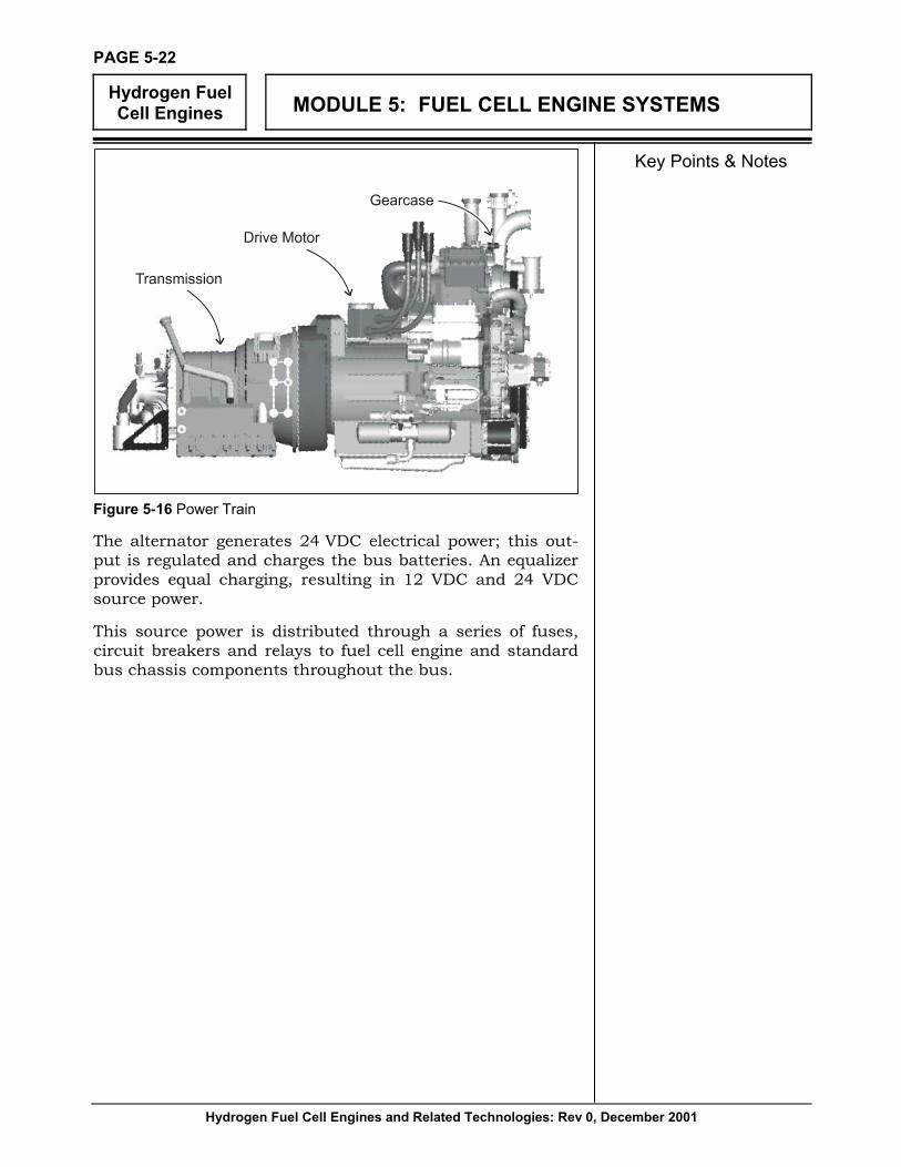
The drive motor transfers mechanical power to the bus driveshaft and to a gearcase. The gearcase drives ancillary components including the alternator, air compressor, stack coolant pump, bus coolant pump, radiator fan motors pump, power steering pump, lubrication oil pump, HVAC refriger-ant compressor and the bus chassis air compressor. A starter motor rotates the drive motor and ancillary compo-nents during startup.
Hydrogen Fuel Cell Engines
MODULE 5: FUEL CELL ENGINE SYSTEMS
Hydrogen Fuel Cell Engines and Related Technologies: Rev 0, December 2001
PAGE 5-22
Key Points & Notes
Figure 5-16 Power Train
The alternator generates 24 VDC electrical power; this out-put is regulated and charges the bus batteries. An equalizer provides equal charging, resulting in 12 VDC and 24 VDC source power.
This source power is distributed through a series of fuses, circuit breakers and relays to fuel cell engine and standard bus chassis components throughout the bus.
Hydrogen Fuel Cell Engines
MODULE 5: FUEL CELL ENGINE SYSTEMS
Hydrogen Fuel Cell Engines and Related Technologies: Rev 0, December 2001
PAGE 5-23
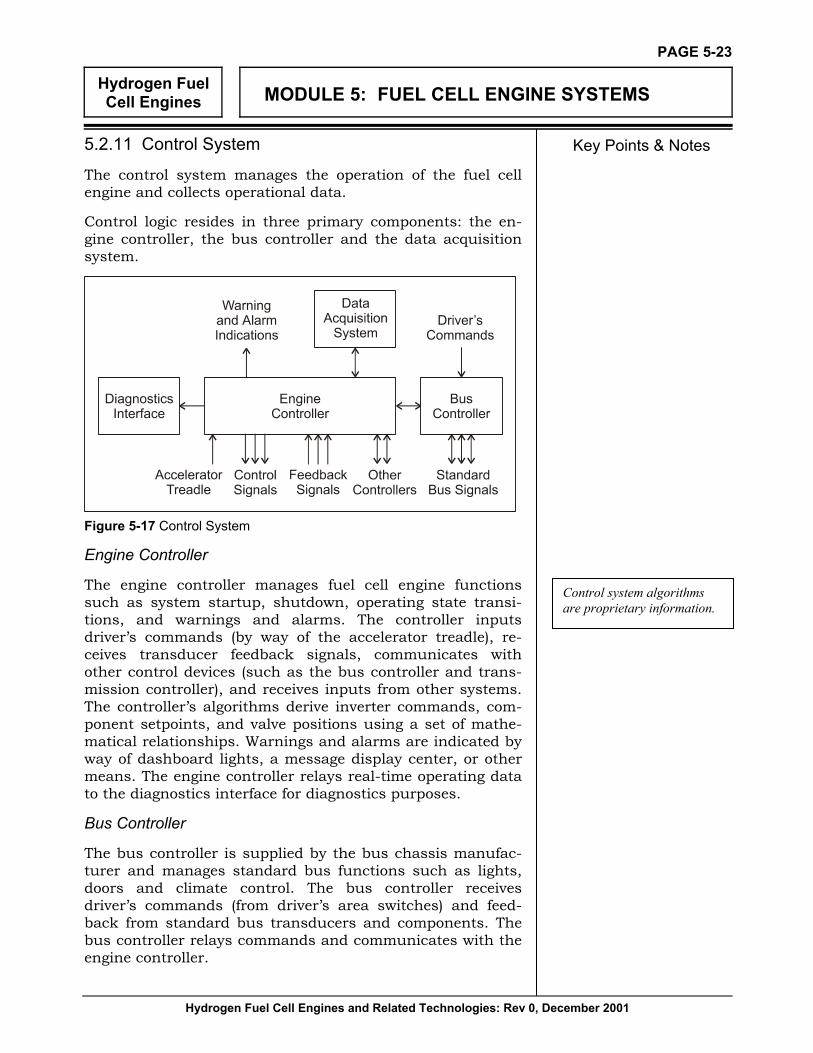
Key Points & Notes 5.2.11 Control System
The control system manages the operation of the fuel cell engine and collects operational data.
Control logic resides in three primary components: the en-gine controller, the bus controller and the data acquisition system.
Figure 5-17 Control System
Engine Controller
The engine controller manages fuel cell engine functions such as system startup, shutdown, operating state transi-tions, and warnings and alarms. The controller inputs driver’s commands (by way of the accelerator treadle), re-ceives transducer feedback signals, communicates with other control devices (such as the bus controller and trans-mission controller), and receives inputs from other systems. The controller’s algorithms derive inverter commands, com-ponent setpoints, and valve positions using a set of mathe-matical relationships. Warnings and alarms are indicated by way of dashboard lights, a message display center, or other means. The engine controller relays real-time operating data to the diagnostics interface for diagnostics purposes.
Bus Controller
The bus controller is supplied by the bus chassis manufac-turer and manages standard bus functions such as lights, doors and climate control. The bus controller receives driver’s commands (from driver’s area switches) and feed-back from standard bus transducers and components. The bus controller relays commands and communicates with the engine controller.
Control system algorithms are proprietary information.
Hydrogen Fuel Cell Engines
MODULE 5: FUEL CELL ENGINE SYSTEMS
Hydrogen Fuel Cell Engines and Related Technologies: Rev 0, December 2001
PAGE 5-24
Key Points & Notes Data Acquisition System
The data acquisition system (DAC) is an optional component installed on some buses to record operating conditions for future analysis. The DAC stores engine controller and other non-control transducer signals on disk whenever the bus is running. These signals can be viewed using the diagnostics interface or downloaded to a host computer.
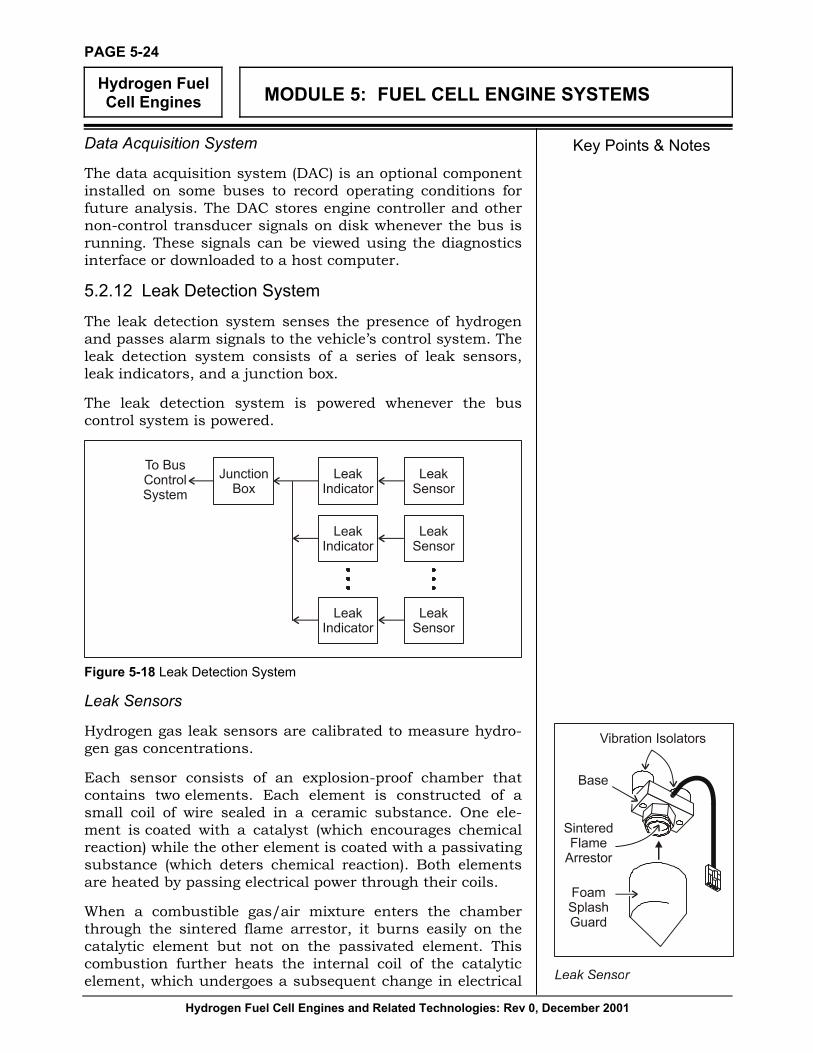
5.2.12 Leak Detection System
The leak detection system senses the presence of hydrogen and passes alarm signals to the vehicle’s control system. The leak detection system consists of a series of leak sensors, leak indicators, and a junction box.
The leak detection system is powered whenever the bus control system is powered.
Figure 5-18 Leak Detection System
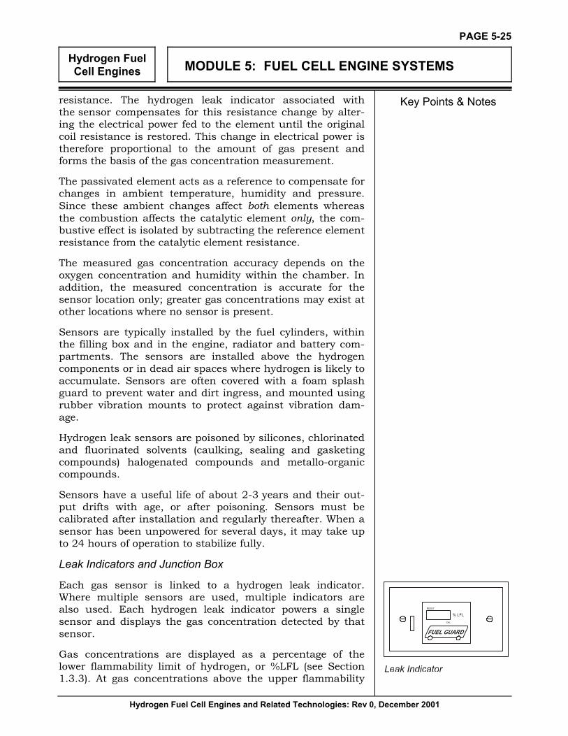
Leak Sensors
Hydrogen gas leak sensors are calibrated to measure hydro-gen gas concentrations.
Each sensor consists of an explosion-proof chamber that contains two elements. Each element is constructed of a small coil of wire sealed in a ceramic substance. One ele-ment is coated with a catalyst (which encourages chemical reaction) while the other element is coated with a passivating substance (which deters chemical reaction). Both elements are heated by passing electrical power through their coils.
When a combustible gas/air mixture enters the chamber through the sintered flame arrestor, it burns easily on the catalytic element but not on the passivated element. This combustion further heats the internal coil of the catalytic element, which undergoes a subsequent change in electrical
Hydrogen Fuel Cell Engines
MODULE 5: FUEL CELL ENGINE SYSTEMS
Hydrogen Fuel Cell Engines and Related Technologies: Rev 0, December 2001
PAGE 5-25
Key Points & Notes resistance. The hydrogen leak indicator associated with the sensor compensates for this resistance change by alter-ing the electrical power fed to the element until the original coil resistance is restored. This change in electrical power is therefore proportional to the amount of gas present and forms the basis of the gas concentration measurement.
The passivated element acts as a reference to compensate for changes in ambient temperature, humidity and pressure. Since these ambient changes affect both elements whereas the combustion affects the catalytic element only, the com-bustive effect is isolated by subtracting the reference element resistance from the catalytic element resistance.
The measured gas concentration accuracy depends on the oxygen concentration and humidity within the chamber. In addition, the measured concentration is accurate for the sensor location only; greater gas concentrations may exist at other locations where no sensor is present.
Sensors are typically installed by the fuel cylinders, within the filling box and in the engine, radiator and battery com-partments. The sensors are installed above the hydrogen components or in dead air spaces where hydrogen is likely to accumulate. Sensors are often covered with a foam splash guard to prevent water and dirt ingress, and mounted using rubber vibration mounts to protect against vibration dam-age.
Hydrogen leak sensors are poisoned by silicones, chlorinated and fluorinated solvents (caulking, sealing and gasketing compounds) halogenated compounds and metallo-organic compounds.
Sensors have a useful life of about 2-3 years and their out-put drifts with age, or after poisoning. Sensors must be calibrated after installation and regularly thereafter. When a sensor has been unpowered for several days, it may take up to 24 hours of operation to stabilize fully.
Leak Indicators and Junction Box
Each gas sensor is linked to a hydrogen leak indicator. Where multiple sensors are used, multiple indicators are also used. Each hydrogen leak indicator powers a single sensor and displays the gas concentration detected by that sensor.
Gas concentrations are displayed as a percentage of the lower flammability limit of hydrogen, or %LFL (see Section 1.3.3). At gas concentrations above the upper flammability

Hydrogen Fuel Cell Engines
MODULE 5: FUEL CELL ENGINE SYSTEMS
Hydrogen Fuel Cell Engines and Related Technologies: Rev 0, December 2001
PAGE 5-26
Key Points & Notes limit (UFL) of hydrogen, there is not enough oxygen in the air/gas mixture for a flame to propagate. Since the sensor operates by burning the gas that enters its explosion-proof chamber, gas concentrations above the UFL cannot be sensed.
When subjected to gas concentrations above the UFL, the sensor quickly indicates a high value (resulting in alarm trigger), but the value drops as the available oxygen depletes. For this reason the high alarm setpoint is latched and does not reset when the gas concentration drops after alarm trig-ger.
When the gas concentration on any hydrogen leak indicator exceeds an internal threshold, a warning or alarm signal is sent from the indicator through a junction box to the control system. The control system then alerts the driver by way of dashboard lights, a message display center, or other means and shuts down the engine if an alarm concentration occurs.
Typical setpoints for leaks are warnings at 5, 10 or 15% and alarm at 25% LFL hydrogen. These setpoints correspond to concentrations of 0.2, 0.4, 0.6 and 1.0% hydrogen in air respectively.

Hydrogen Fuel Cell Engines
MODULE 5: FUEL CELL ENGINE SYSTEMS
Hydrogen Fuel Cell Engines and Related Technologies: Rev 0, December 2001
PAGE 5-27
Key Points & Notes 5.2.13 Fire Suppression System
The fire suppression system protects against fire and passes alarm signals to the vehicle’s control system. The fire sup-pression system may be organized in a series of zones that serve specific areas in the bus. Each zone may or may not contain fire sensors, thermal wire, fire retardant tanks and nozzles.
Figure 5-19 Fire Suppression System The fire suppression system is active at all times, unless battery power is interrupted. The bus control system does not need to be active for the fire suppression system to func-tion, although the dashboard lights, message display center, or other driver indicators will not come on when the control system is off.
Fire Sensors and Thermal Wire
Fire sensors are located in areas of highest fire probability and are installed in a particular orientation to cover the area of interest.
Each fire sensor monitors two separate bands of infrared energy throughout a 90° solid cone field of view to a trigger distance of 5 feet (1.5 m). A sensor triggers (within 10 ms) whenever it detects the infrared energy pattern characteristic of a fire. In this way the sensor remains immune to false alarms from sunlight, flashlights, lightning, headlights, incandescent lights (100 W at 2 in; 5 cm) and welding arcs (at greater than 30 in; 76 cm) all of which have different energy patterns. The fire sensors do not detect high tempera-
Fire sensors to detect hydrogen fires must use optical (IR- or UV-type) detection principles. Thermal-type fire sensors are not suitable.
Hydrogen Fuel Cell Engines
MODULE 5: FUEL CELL ENGINE SYSTEMS
Hydrogen Fuel Cell Engines and Related Technologies: Rev 0, December 2001
PAGE 5-28
Key Points & Notes tures, only flames. A green LED on each sensor comes on whenever that sensor has electrical power.
Thermal wire is wound in close contact with the fuel cell stacks. Each wire consists of two separate conductors wound together but separated by insulation. This insulation is designed to melt at 356 ºF (180 ºC) temperature, causing the conductors to come into contact thereby creating a short circuit.
The sensors and thermal wire within each zone are wired in series and are terminated by an end-of-line resistor attached to the last sensor in the series. If any device trips within a series, a discrete ground signal is sent to the fire suppres-sion system controller resulting in a fire alarm. If a sensor fault occurs or the end-of-line resistor is missing, the con-troller detects incorrect impedance within the series result-ing in a system fault warning.
When a warning or alarm occurs, the fire suppression sys-tem controller sends a signal to the bus control system. The bus control system then alerts the driver by way of dash-board lights, a message display center, or other means. The bus shuts down automatically in the event of a fire and the fire retardant discharges soon after if the affected area in-cludes a fire retardant tank and nozzles.
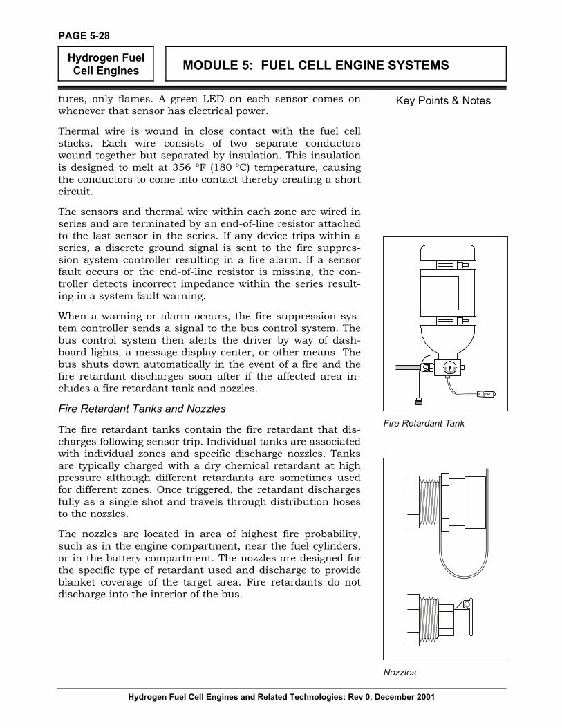
Fire Retardant Tanks and Nozzles
The fire retardant tanks contain the fire retardant that dis-charges following sensor trip. Individual tanks are associated with individual zones and specific discharge nozzles. Tanks are typically charged with a dry chemical retardant at high pressure although different retardants are sometimes used for different zones. Once triggered, the retardant discharges fully as a single shot and travels through distribution hoses to the nozzles.
The nozzles are located in area of highest fire probability, such as in the engine compartment, near the fuel cylinders, or in the battery compartment. The nozzles are designed for the specific type of retardant used and discharge to provide blanket coverage of the target area. Fire retardants do not discharge into the interior of the bus.


![A novel energy storage system incorporating electrically ...mezhao/pdf/356.pdf · hydrogen storage system, in which hydrogen is employed as the fuel [10]. Hydrogen can be generated](https://static.fdocuments.in/doc/165x107/600974963a68f047865000d5/a-novel-energy-storage-system-incorporating-electrically-mezhaopdf356pdf.jpg)


![Hydrogen Storage Materials171627/FULLTEXT01.pdf · drogen fuel feasible, is that of hydrogen storage [1, 2]. This is the main topic of the present thesis. A hydrogen storage system](https://static.fdocuments.in/doc/165x107/60699f7a18f2d938cb1f17bf/hydrogen-storage-171627fulltext01pdf-drogen-fuel-feasible-is-that-of-hydrogen.jpg)
