Hydro-Pyro Integration in the processing of Nickel Laterites · Hydro-Pyro Integration in the...
25
Hydro-Pyro Integration in the processing of Nickel Laterites Authors: Anne Oxley a, b and Dr Nic Barcza c a. Alyssum Ventures Ltd, Isle of Man, IM8 1JA, United Kingdom b. Scientific Associate of the Natural History Museum, London, UK c. Independent Metallurgical Consultant, RSA Keywords Nickel Laterites; Hydrometallurgical Pyrometallurgical Integration; Heap Leaching; Nickel and Cobalt Abstract Hydrometallurgical process routes are seen to be the future of treatment of the lower grade nickel laterites ores. Hydrometallurgical projects of recent years have focused on HPAL and have been largely unsuccessful economically so far, with huge capital cost overruns. The simplest and least capital intensive of the possible alternatives to HPAL is atmospheric heap leaching. Development work is also underway by several companies into atmospheric tank leaching which is also a potentially viable alternative. The natural product for a leaching process is a high grade nickel intermediate either from a direct precipitation process (containing approx. 36% Ni) or via Ion Exchange (>50% Ni). There are many existing pyrometallurgical facilities which could easily be adapted to take this nickel intermediate giving them significant potential benefits especially as nickel laterite ore grades diminish. The nickel production from these plants could also be increased and for new plants large capital and operating cost savings achieved by using suitable intermediates. There are also potential environmental benefits with much less energy consumed and lower greenhouse gases emitted per tonne of nickel produced. In the future an integrated hydrometallurgical plant with attached existing smelter or a more advanced pyrometallurgical smelting process (e.g. a DC Arc Furnace) could well be the way forward for new projects.
Transcript of Hydro-Pyro Integration in the processing of Nickel Laterites · Hydro-Pyro Integration in the...
Hydro-Pyro Integration in the processing of Nickel Laterites Authors: Anne Oxley a, b and Dr Nic Barcza c
a. Alyssum Ventures Ltd, Isle of Man, IM8 1JA, United Kingdom b. Scientific Associate of the Natural History Museum, London, UK c. Independent Metallurgical Consultant, RSA
Keywords Nickel Laterites; Hydrometallurgical Pyrometallurgical Integration; Heap Leaching; Nickel and Cobalt
Abstract Hydrometallurgical process routes are seen to be the future of treatment of the lower grade nickel laterites ores. Hydrometallurgical projects of recent years have focused on HPAL and have been largely unsuccessful economically so far, with huge capital cost overruns. The simplest and least capital intensive of the possible alternatives to HPAL is atmospheric heap leaching. Development work is also underway by several companies into atmospheric tank leaching which is also a potentially viable alternative. The natural product for a leaching process is a high grade nickel intermediate either from a direct precipitation process (containing approx. 36% Ni) or via Ion Exchange (>50% Ni). There are many existing pyrometallurgical facilities which could easily be adapted to take this nickel intermediate giving them significant potential benefits especially as nickel laterite ore grades diminish. The nickel production from these plants could also be increased and for new plants large capital and operating cost savings achieved by using suitable intermediates. There are also potential environmental benefits with much less energy consumed and lower greenhouse gases emitted per tonne of nickel produced. In the future an integrated hydrometallurgical plant with attached existing smelter or a more advanced pyrometallurgical smelting process (e.g. a DC Arc Furnace) could well be the way forward for new projects.
A. Oxley et al. / Minerals Engineering 54 (2013) 2–13
1 Introduction – Global Nickel Laterite Production
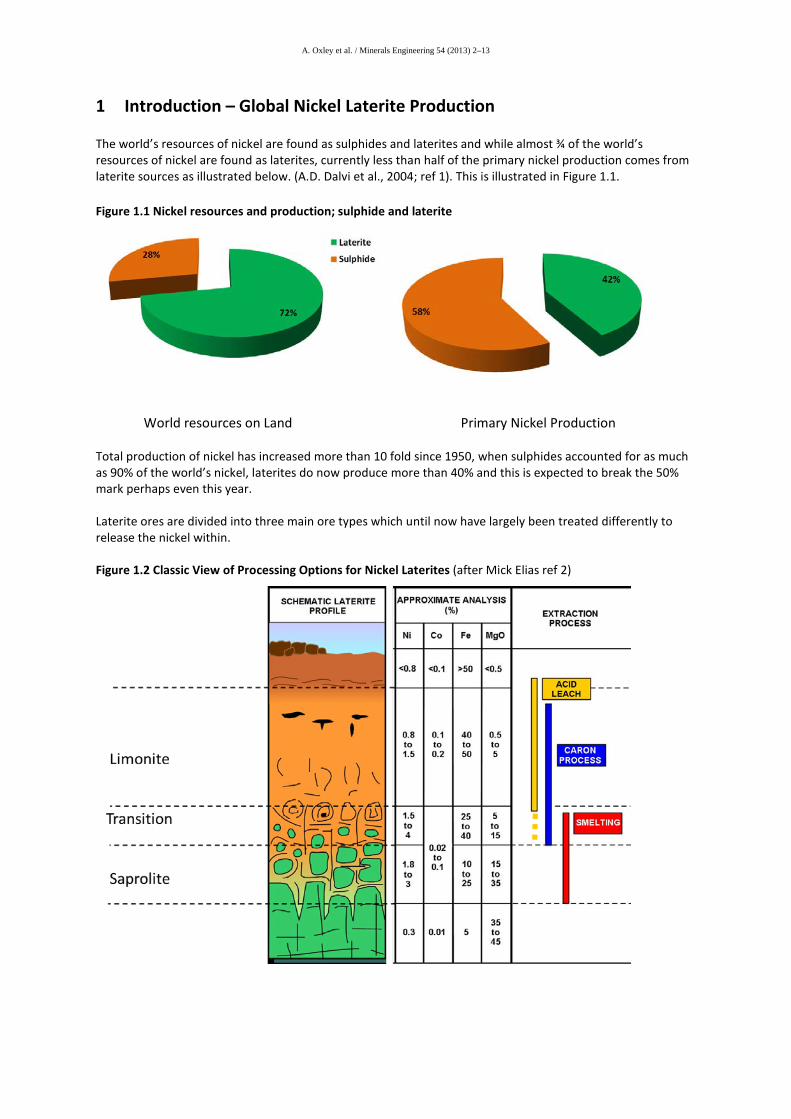
The world’s resources of nickel are found as sulphides and laterites and while almost ¾ of the world’s resources of nickel are found as laterites, currently less than half of the primary nickel production comes from laterite sources as illustrated below. (A.D. Dalvi et al., 2004; ref 1). This is illustrated in Figure 1.1.
Figure 1.1 Nickel resources and production; sulphide and laterite World resources on Land Primary Nickel Production Total production of nickel has increased more than 10 fold since 1950, when sulphides accounted for as much as 90% of the world’s nickel, laterites do now produce more than 40% and this is expected to break the 50% mark perhaps even this year. Laterite ores are divided into three main ore types which until now have largely been treated differently to release the nickel within. Figure 1.2 Classic View of Processing Options for Nickel Laterites (after Mick Elias ref 2)
A. Oxley et al. / Minerals Engineering 54 (2013) 2–13
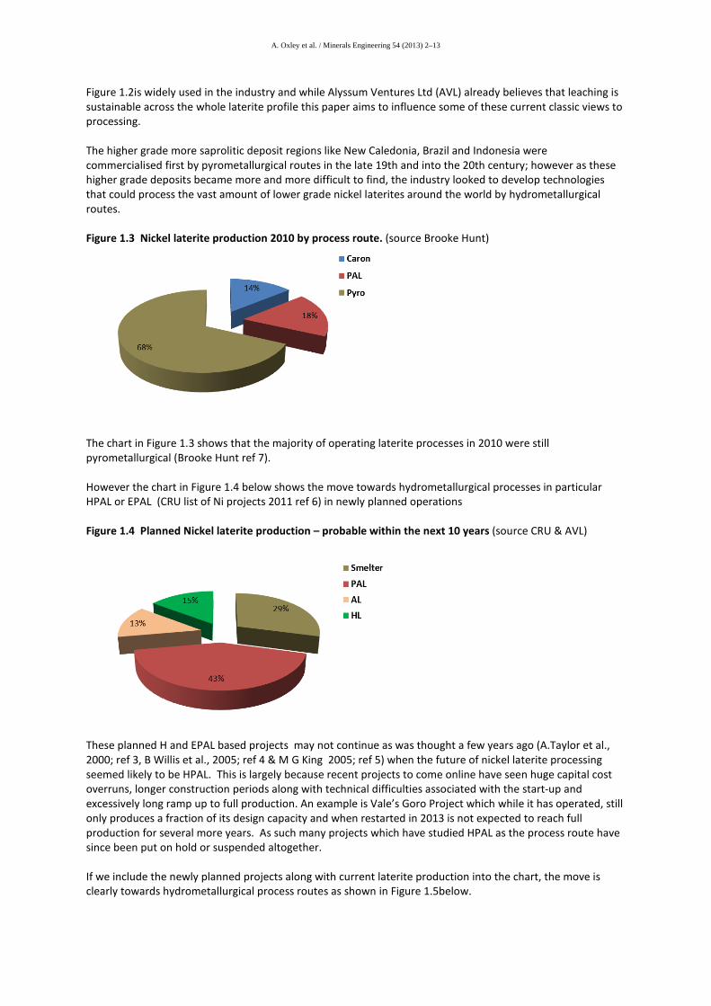
Figure 1.2is widely used in the industry and while Alyssum Ventures Ltd (AVL) already believes that leaching is sustainable across the whole laterite profile this paper aims to influence some of these current classic views to processing. The higher grade more saprolitic deposit regions like New Caledonia, Brazil and Indonesia were commercialised first by pyrometallurgical routes in the late 19th and into the 20th century; however as these higher grade deposits became more and more difficult to find, the industry looked to develop technologies that could process the vast amount of lower grade nickel laterites around the world by hydrometallurgical routes. Figure 1.3 Nickel laterite production 2010 by process route. (source Brooke Hunt)
The chart in Figure 1.3 shows that the majority of operating laterite processes in 2010 were still pyrometallurgical (Brooke Hunt ref 7). However the chart in Figure 1.4 below shows the move towards hydrometallurgical processes in particular HPAL or EPAL (CRU list of Ni projects 2011 ref 6) in newly planned operations Figure 1.4 Planned Nickel laterite production – probable within the next 10 years (source CRU & AVL)
These planned H and EPAL based projects may not continue as was thought a few years ago (A.Taylor et al., 2000; ref 3, B Willis et al., 2005; ref 4 & M G King 2005; ref 5) when the future of nickel laterite processing seemed likely to be HPAL. This is largely because recent projects to come online have seen huge capital cost overruns, longer construction periods along with technical difficulties associated with the start-up and excessively long ramp up to full production. An example is Vale’s Goro Project which while it has operated, still only produces a fraction of its design capacity and when restarted in 2013 is not expected to reach full production for several more years. As such many projects which have studied HPAL as the process route have since been put on hold or suspended altogether. If we include the newly planned projects along with current laterite production into the chart, the move is clearly towards hydrometallurgical process routes as shown in Figure 1.5below.
A. Oxley et al. / Minerals Engineering 54 (2013) 2–13
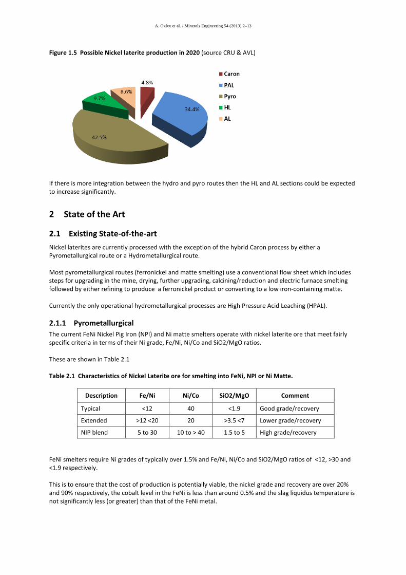
Figure 1.5 Possible Nickel laterite production in 2020 (source CRU & AVL)
If there is more integration between the hydro and pyro routes then the HL and AL sections could be expected to increase significantly.
2 State of the Art
2.1 Existing State-of-the-art Nickel laterites are currently processed with the exception of the hybrid Caron process by either a Pyrometallurgical route or a Hydrometallurgical route. Most pyrometallurgical routes (ferronickel and matte smelting) use a conventional flow sheet which includes steps for upgrading in the mine, drying, further upgrading, calcining/reduction and electric furnace smelting followed by either refining to produce a ferronickel product or converting to a low iron-containing matte. Currently the only operational hydrometallurgical processes are High Pressure Acid Leaching (HPAL).
2.1.1 Pyrometallurgical The current FeNi Nickel Pig Iron (NPI) and Ni matte smelters operate with nickel laterite ore that meet fairly specific criteria in terms of their Ni grade, Fe/Ni, Ni/Co and SiO2/MgO ratios. These are shown in Table 2.1 Table 2.1 Characteristics of Nickel Laterite ore for smelting into FeNi, NPI or Ni Matte.
Description Fe/Ni Ni/Co SiO2/MgO Comment
Typical <12 40 <1.9 Good grade/recovery
Extended >12 <20 20 >3.5 <7 Lower grade/recovery
NIP blend 5 to 30 10 to > 40 1.5 to 5 High grade/recovery FeNi smelters require Ni grades of typically over 1.5% and Fe/Ni, Ni/Co and SiO2/MgO ratios of <12, >30 and <1.9 respectively. This is to ensure that the cost of production is potentially viable, the nickel grade and recovery are over 20% and 90% respectively, the cobalt level in the FeNi is less than around 0.5% and the slag liquidus temperature is not significantly less (or greater) than that of the FeNi metal.
A. Oxley et al. / Minerals Engineering 54 (2013) 2–13
FeNi alloys have a liquidus temperature of around 1500 °C and require the furnace operation to be at least 50 °C higher to ensure successful tapping of the metal and minimise skull formation in the launders and ladles. High slag super-heat levels of over 100 °C can cause severe furnace refractory containment challenges and necessitate the use of special copper coolers in the side wall. Furthermore lack of sufficient superheat can cause the metal to freeze in the furnace. Measures to try and prevent this can lead in some instances to overheating the slag and to refractory damage. The conventional approach to resolving this issue is to smelt a low liquidus temperature matte by adding sulphur normally as pyrite instead of producing FeNi. This allows the furnace (electric and in some instances coke fired shaft furnaces) to be operated at temperatures of around 1350 to 1400°C. However the matte produced has lower Ni grades of around 10% and require converting to remove iron followed by leaching. The benefit of this type of flow sheet is the optional recovery of cobalt units. However there are several disadvantages such as SO2 emissions, processing of mattes and expensive coke consumption in the case of shaft furnaces. An alternative approach is to overcome the slag superheat constraint by decreasing the FeO content of the slag using additional carbon-containing reductant in the feed to the furnace. The reduction of the FeO in the slag can have a major impact on the liquidus temperature in slags with high SiO2/MgO ratios (> 2) increasing it by up to 200 °C at ratios of over 3.5. However the additional reduction of iron oxide lowers the Ni grade (albeit normally increasing the Ni recovery to some extent) and can result FeNi with Ni contents well below the normal specification of 20% (i.e. typically between 5 and 15%). These low Ni grades are typical of nickel pig iron (NPI) that has grown significantly as a source of nickel units in the past ten years especially in China. The best way to overcome this lowering of the FeNi grade and achieving an acceptable slag liquidus temperature is to blend a suitable proportion of NIP into the feed to the furnace. Additions of between 5 and 10% calcined NIP containing over 90% Ni as oxide can result in a FeNi grade of over 25% Ni and a slag with a liquidus of 1650 °C that would have otherwise been below 1400 °C. This approach can allow existing FeNi smelters to expand their operations or extend the life of their projects by introducing higher Fe/Ni and SiO2/MgO ratio transition and limonitic ores while still meeting acceptable criteria for smelting conditions and FeNi product specifications as detailed further below.
2.1.2 Hydrometallurgical Processes
2.1.2.1 High Pressure Acid Leaching HPAL Other than the hybrid Caron process the only operating hydrometallurgical process for nickel laterites are HPALs. The first commercial HPAL plant started production in 1959 at Moa Bay in Cuba and still continues today and Sherrit a 50% joint venture (JV) partner in Moa is a partner in the construction of the similar Ambatovy project in Madagascar. HPAL processes require ores that are predominantly limonitic; have lower Mg- usually limited to <4 % and require lower Al content. The pressure leaching is carried out either in pachuka tanks (Moa Bay) or titanium lined autoclaves (all modern plants). Leach temperatures vary in the range 245 to 270°C. Solid-liquid separation is carried out by Counter-Current Decantation (CCD). There are various ways of purifying the nickel containing solution and separating nickel and cobalt. In modern plants such separation is carried out by solvent extraction (SX). Final products produced are electro-nickel, nickel oxide or nickel briquettes. Some plants produce intermediate materials (mixed sulphides or mixed hydroxides) that are refined elsewhere. After Moa Bay no new plants were built until the late nineteen nineties which saw first Bulong, then Cawse and finally in 1999 Murrin Murrin was completed. Once built all of these projects produce nickel in products at
A. Oxley et al. / Minerals Engineering 54 (2013) 2–13
relatively low operating costs but the cost of construction was significant and both Bulong and Cawse are now closed. While many projects have studied the use of HPAL and still do there have only been 2 recent additions to the HPAL family.
1. Vale’s Goro Nickel project in New Caledonia. This plant is now in operation but has suffered many technical difficulties and still is far from operating successfully at anywhere near its design capacity.
2. Ravensthorpe Nickel project in WA. BHP Billiton built this EPAL plant which commenced operation in 2008 only to shut-down due to technical issues and a low nickel price and was then sold to First Quantum who refitted the plant and started production in 2011 and are now well advanced with the ramp-up phase.
There is another plant, Rio Tuba, in the Philippines operated by Sumitomo and partners which is smaller and has operated successfully. An expansion and a possible further new plant is planned in the near future by the partnership operating Rio Tuba.
2.1.2.2 Heap Leaching Heap leaching is well established process used for the treatment of copper, gold and uranium and it is now being used in varying degrees by established companies such as Glencore (Minara), Vale, BHPB and Xstrata for nickel laterites. The heap leach process has the potential to be the lowest capital cost and most environmentally friendly of the leach processes for nickel laterites. It has been demonstrated on a large scale by companies as follows:
• European Nickel (ENK) at its Çaldağ project this project has since been sold and new Turkish owners are continuing to commercialise the heap leach, site preparation has begun for the commercial heap leach operation with full construction expected Q1 2013.
• ENK at the Acoje project in the Philippines. • Glencore (Minara) at Murrin Murrin which has commercially heap leached more than 1,000,000
tonnes of nickel laterite ore to give greater flexibility to the HPAL circuit. • BHP Billiton has demonstrated on a large scale the heap leach process at Cerro Matoso. • Both Vale and Xstrata have conducted various testing with respect to heap leaching.
The following are some of the projects that are currently in the study or construction phase of a nickel laterite heap leach project Table 2.2 HL Projects
Project Location Owner/Partners Stage Çaldağ Turkey Pre-construction
(financing) Cleopatra Oregon USA RFN PEA Cerro Matoso Colombia BHPBilliton FS Piaui Brazil Vale PFS+ Jacari Brazil Anglo PFS+ NiWest Australia GME PFS
A. Oxley et al. / Minerals Engineering 54 (2013) 2–13
2.1.2.3 Atmospheric Tank Leaching - AL Atmospheric tank leaching whereby the saprolite or limonite is leached in a tank at elevated temperatures but at atmospheric pressure. This process has not yet been seriously demonstrated on a large scale but several projects are considering commercialisation.
Table 2.3 AL Projects Project Location Owner/Partners Stage Expected
Operation Dutwa Tanzania African Eagle PFS 2018 Weda Bay Halmahera
Indonesia Eramet Final
Design/Engineering 2015
Acoje Philippines ENK/DMCI BFS ? Yerilla Australia Heron Resources PFS ?
Reviews of Hydrometallurgical process routes include those of Reid, J. and S. Barnett 2002 and Taylor, A., 2007 (Refs 8 & 9)
2.2 Advances to the state of the art There have been some advances to both the pyro and hydro routes over recent years these outlined briefly below.
2.2.1 Pyro 1. The smelting of Nickel Pig Iron (5 to 10% Ni mostly in China) from laterite ore grades that are not suitable for producing standard grades of FeNi (20 to 45% Ni). The low liquidus temperature of NPI with higher carbon and silicon contents allows lower furnace operating temperatures and hence lower melting point slags to be used with SiO2/MgO ratios of typically 2 and up to 5. However this is a high cost option so most plants in China are swing producers or integrated with stainless steel plants and so benefit from hot metal transfer to the melt shop . 2. The smelting of Ni laterite ore fines in suitably designed unit operations such as fluidised bed (FB) systems and DC arc furnaces (for example the 12 MW DC arc furnace at Southern Urals Nickel Plant SUNP (in Russia) (Naudé, C.P et al., 2010; ref 11) and Xstrata's Koniambo plant in New Caledonia with two 80 MW twin electrode DC arc furnaces that are fed with pre-reduced hot calcine produced in a fines based pre-treatment facility) due for commissioning by end 2012/early 2013.
2.2.2 Hydrometallurgical processing
1. EPAL – this a process which combines the HPAL for the limonitic ore and a further atmospheric tank leach for the saprolite ore. This step neutralises acid remaining in the pregnant liquor of the HPAL stream with the saprolite ore, also achieving some extraction from the saprolite (approx. 60-70%) with no further acid addition. Ravensthorpe is an EPAL plant.
2. Staged AL – this process uses different ore fractions in later stages of AL to utilise excess acid remaining from the initial limonite AL.
3. Ion Exchange of PLS – most new HL & AL projects are currently looking to incorporate some form of ion exchange into the downstream treatment of the PLS to produce a higher grade purer nickel product and perhaps other separate saleable products.
A. Oxley et al. / Minerals Engineering 54 (2013) 2–13
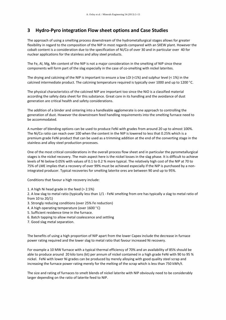
3 Hydro-Pyro integration Flow sheet options and Case Studies
The approach of using a smelting process downstream of the hydrometallurgical stages allows for greater flexibility in regard to the composition of the NIP in most regards compared with an SXEW plant. However the cobalt content is a consideration due to the specification of Ni/Co of over 30 and in particular over 40 for nuclear applications for the stainless and alloy steel products. The Fe, Al, Mg, Mn content of the NIP is not a major consideration in the smelting of NIP since these components will form part of the slag especially in the case of co-smelting with nickel laterites. The drying and calcining of the NIP is important to ensure a low LOI (<1%) and sulphur level (< 1%) in the calcined intermediate product. The calcining temperature required is typically over 1000 and up to 1200 °C. The physical characteristics of the calcined NIP are important too since the NiO is a classified material according the safety data sheet for this substance. Great care in its handling and the avoidance of dust generation are critical health and safety considerations. The addition of a binder and sintering into a handleable agglomerate is one approach to controlling the generation of dust. However the downstream feed handling requirements into the smelting furnace need to be accommodated. A number of blending options can be used to produce FeNi with grades from around 20 up to almost 100%. The Ni/Co ratio can reach over 100 when the content in the NIP is lowered to less that 0.25% which is a premium grade FeNi product that can be used as a trimming addition at the end of the converting stage in the stainless and alloy steel production processes. One of the most critical considerations in the overall process flow sheet and in particular the pyrometallurgical stages is the nickel recovery. The main aspect here is the nickel losses in the slag phase. It is difficult to achieve levels of Ni below 0.05% with values of 0.1 to 0.2 % more typical. The relatively high cost of the NIP at 70 to 75% of LME implies that a recovery of over 99% must be achieved especially if the NIP is purchased by a non-integrated producer. Typical recoveries for smelting laterite ores are between 90 and up to 95%. Conditions that favour a high recovery include: 1. A high Ni head grade in the feed (> 2.5%) 2. A low slag to metal ratio (typically less than 1/1 - FeNi smelting from ore has typically a slag to metal ratio of from 10 to 20/1) 3. Strongly reducing conditions (over 25% Fe reduction) 4. A high operating temperature (over 1600 °C) 5. Sufficient residence time in the furnace. 6. Batch tapping to allow metal coalescence and settling 7. Good slag metal separation. The benefits of using a high proportion of NIP apart from the lower Capex include the decrease in furnace power rating required and the lower slag to metal ratio that favour increased Ni recovery. For example a 10 MW furnace with a typical thermal efficiency of 70% and an availability of 85% should be able to produce around 20 kilo tons (kt) per annum of nickel contained in a high grade FeNi with 90 to 95 % nickel. FeNi with lower Ni grades can be produced by merely alloying with good quality steel scrap and increasing the furnace power rating merely for the melting of the scrap which is less than 750 kWh/t. The size and rating of furnaces to smelt blends of nickel laterite with NIP obviously need to be considerably larger depending on the ratio of laterite feed to NIP.
A. Oxley et al. / Minerals Engineering 54 (2013) 2–13
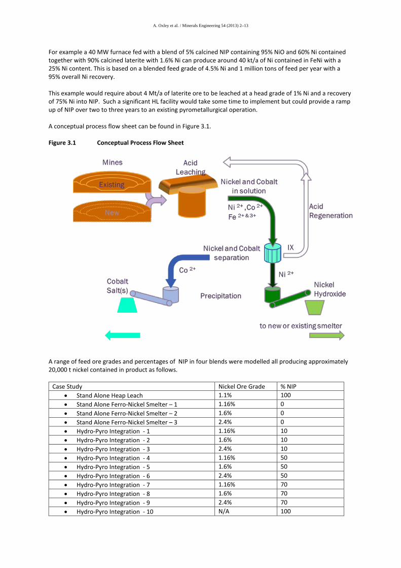
For example a 40 MW furnace fed with a blend of 5% calcined NIP containing 95% NiO and 60% Ni contained together with 90% calcined laterite with 1.6% Ni can produce around 40 kt/a of Ni contained in FeNi with a 25% Ni content. This is based on a blended feed grade of 4.5% Ni and 1 million tons of feed per year with a 95% overall Ni recovery. This example would require about 4 Mt/a of laterite ore to be leached at a head grade of 1% Ni and a recovery of 75% Ni into NIP. Such a significant HL facility would take some time to implement but could provide a ramp up of NIP over two to three years to an existing pyrometallurgical operation. A conceptual process flow sheet can be found in Figure 3.1. Figure 3.1 Conceptual Process Flow Sheet
A range of feed ore grades and percentages of NIP in four blends were modelled all producing approximately 20,000 t nickel contained in product as follows.
Case Study Nickel Ore Grade % NIP • Stand Alone Heap Leach 1.1% 100 • Stand Alone Ferro-Nickel Smelter – 1 1.16% 0 • Stand Alone Ferro-Nickel Smelter – 2 1.6% 0 • Stand Alone Ferro-Nickel Smelter – 3 2.4% 0 • Hydro-Pyro Integration - 1 1.16% 10 • Hydro-Pyro Integration - 2 1.6% 10 • Hydro-Pyro Integration - 3 2.4% 10 • Hydro-Pyro Integration - 4 1.16% 50 • Hydro-Pyro Integration - 5 1.6% 50 • Hydro-Pyro Integration - 6 2.4% 50 • Hydro-Pyro Integration - 7 1.16% 70 • Hydro-Pyro Integration - 8 1.6% 70 • Hydro-Pyro Integration - 9 2.4% 70 • Hydro-Pyro Integration - 10 N/A 100
A. Oxley et al. / Minerals Engineering 54 (2013) 2–13
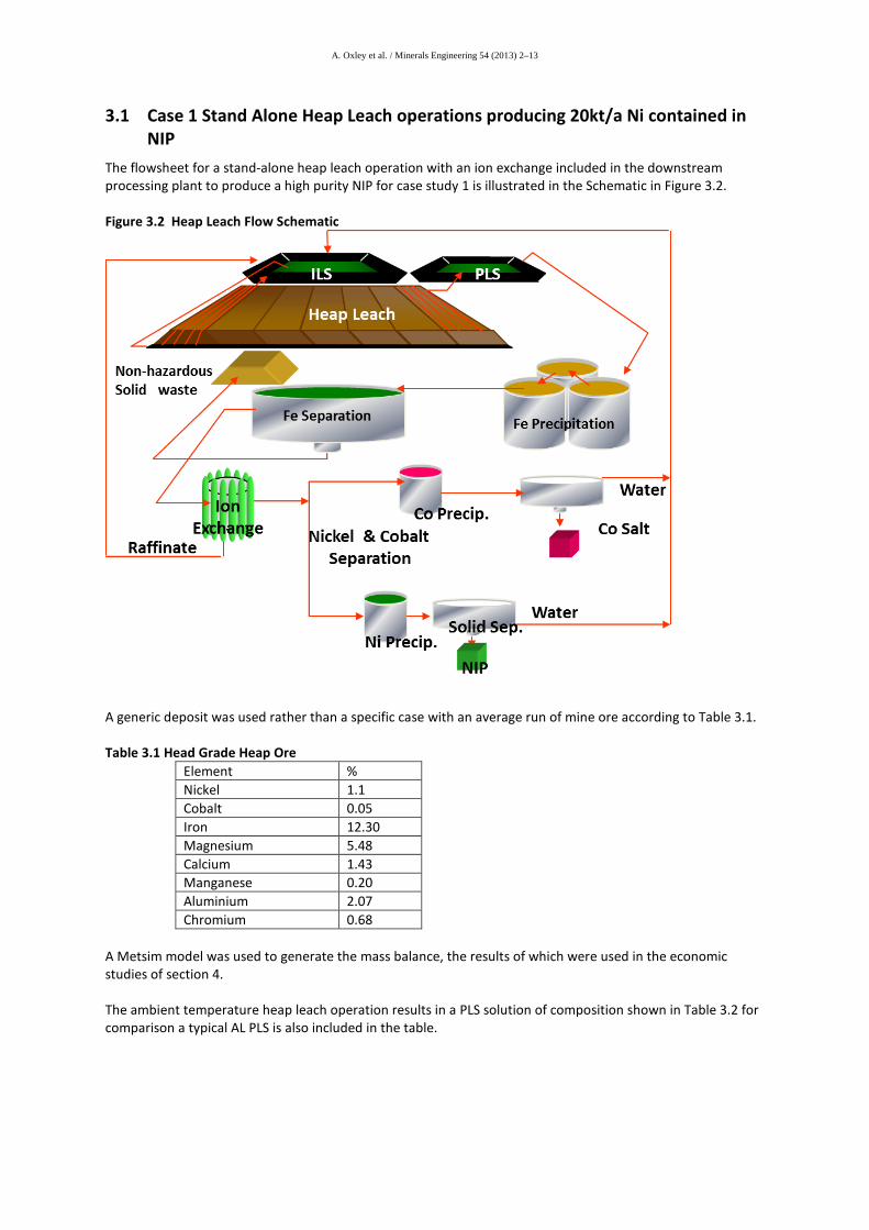
3.1 Case 1 Stand Alone Heap Leach operations producing 20kt/a Ni contained in NIP
The flowsheet for a stand-alone heap leach operation with an ion exchange included in the downstream processing plant to produce a high purity NIP for case study 1 is illustrated in the Schematic in Figure 3.2. Figure 3.2 Heap Leach Flow Schematic
A generic deposit was used rather than a specific case with an average run of mine ore according to Table 3.1. Table 3.1 Head Grade Heap Ore
Element % Nickel 1.1 Cobalt 0.05 Iron 12.30 Magnesium 5.48 Calcium 1.43 Manganese 0.20 Aluminium 2.07 Chromium 0.68
A Metsim model was used to generate the mass balance, the results of which were used in the economic studies of section 4. The ambient temperature heap leach operation results in a PLS solution of composition shown in Table 3.2 for comparison a typical AL PLS is also included in the table.
A. Oxley et al. / Minerals Engineering 54 (2013) 2–13
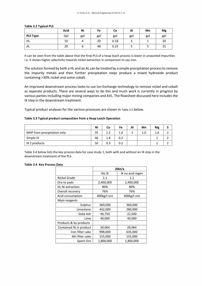
Table 3.2 Typical PLS Acid Ni Fe Co Al Mn Mg PLS Type Gpl gpl gpl gpl gpl gpl gpl HL 10 4 20 0.18 3 1 20 AL 20 6 48 0.25 5 5 25
It can be seen from the table above that the final PLS of a heap leach process is lower in unwanted impurities i.e. it shows higher selectivity towards nickel extraction in comparison to say iron. The solution formed by both a HL and an AL can be treated by a simple precipitation process to remove the impurity metals and then further precipitation steps produce a mixed hydroxide product containing >30% nickel and some cobalt. An improved downstream process looks to use Ion Exchange technology to remove nickel and cobalt as separate products. There are several ways to do this and much work is currently in progress by various parties including major mining companies and AVL. The flowsheet discussed here includes the IX step in the downstream treatment. Typical product analyses for the various processes are shown in Table 3.3 below. Table 3.3 Typical product composition from a Heap Leach Operation
Ni Co Fe Al Mn Mg S MHP from precipitation only 35 1.2 1.0 1 1.0 1.6 2 Simple IX 46 1.8 0.2 1 2 IX 2 products 50 0.3 0.2 1 2
Table 3.4 below lists the key process data for case study 1, both with and without an IX step in the downstream treatment of the PLS. Table 3.4 Key Process Data
20kt/a No IX IX no acid regen
Nickel Grade 1.1 1.1 Ore to pads 2,400,000 2,400,000 HL Ni extraction 80% 80% Overall recovery 76% 76% Acid consumption 400kg/t ore 400kg/t ore Main reagents
Sulphur 360,000 360,000 Limestone 442,000 280,000
Soda Ash 46,750 22,500 Lime 40,000 40,000
Products & by products Contained Ni in product 20,064 20,064
Iron filter cake 998,000 635,000 Mn filter cake 155,000 155,000
Spent Ore 1,800,000 1,800,000
A. Oxley et al. / Minerals Engineering 54 (2013) 2–13
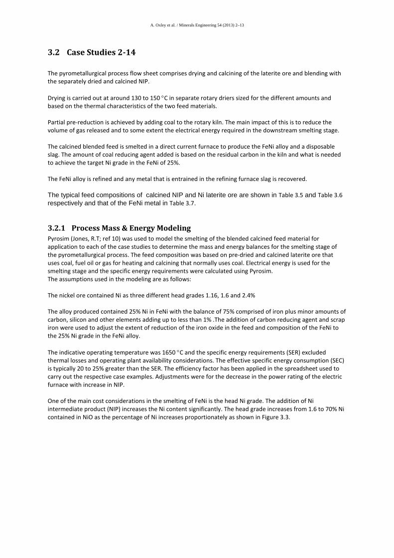
3.2 Case Studies 2-14 The pyrometallurgical process flow sheet comprises drying and calcining of the laterite ore and blending with the separately dried and calcined NIP. Drying is carried out at around 130 to 150 °C in separate rotary driers sized for the different amounts and based on the thermal characteristics of the two feed materials. Partial pre-reduction is achieved by adding coal to the rotary kiln. The main impact of this is to reduce the volume of gas released and to some extent the electrical energy required in the downstream smelting stage. The calcined blended feed is smelted in a direct current furnace to produce the FeNi alloy and a disposable slag. The amount of coal reducing agent added is based on the residual carbon in the kiln and what is needed to achieve the target Ni grade in the FeNi of 25%. The FeNi alloy is refined and any metal that is entrained in the refining furnace slag is recovered. The typical feed compositions of calcined NIP and Ni laterite ore are shown in Table 3.5 and Table 3.6 respectively and that of the FeNi metal in Table 3.7.
3.2.1 Process Mass & Energy Modeling Pyrosim (Jones, R.T; ref 10) was used to model the smelting of the blended calcined feed material for application to each of the case studies to determine the mass and energy balances for the smelting stage of the pyrometallurgical process. The feed composition was based on pre-dried and calcined laterite ore that uses coal, fuel oil or gas for heating and calcining that normally uses coal. Electrical energy is used for the smelting stage and the specific energy requirements were calculated using Pyrosim. The assumptions used in the modeling are as follows: The nickel ore contained Ni as three different head grades 1.16, 1.6 and 2.4% The alloy produced contained 25% Ni in FeNi with the balance of 75% comprised of iron plus minor amounts of carbon, silicon and other elements adding up to less than 1% .The addition of carbon reducing agent and scrap iron were used to adjust the extent of reduction of the iron oxide in the feed and composition of the FeNi to the 25% Ni grade in the FeNi alloy. The indicative operating temperature was 1650 °C and the specific energy requirements (SER) excluded thermal losses and operating plant availability considerations. The effective specific energy consumption (SEC) is typically 20 to 25% greater than the SER. The efficiency factor has been applied in the spreadsheet used to carry out the respective case examples. Adjustments were for the decrease in the power rating of the electric furnace with increase in NIP. One of the main cost considerations in the smelting of FeNi is the head Ni grade. The addition of Ni intermediate product (NIP) increases the Ni content significantly. The head grade increases from 1.6 to 70% Ni contained in NiO as the percentage of Ni increases proportionately as shown in Figure 3.3.
A. Oxley et al. / Minerals Engineering 54 (2013) 2–13
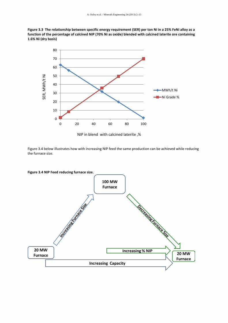
Figure 3.3 The relationship between specific energy requirement (SER) per ton Ni in a 25% FeNi alloy as a function of the percentage of calcined NIP (70% Ni as oxide) blended with calcined laterite ore containing 1.6% Ni (dry basis)
Figure 3.4 below illustrates how with increasing NIP feed the same production can be achieved while reducing the furnace size. Figure 3.4 NIP Feed reducing furnace size.
0
10
20
30
40
50
60
70
80
0 20 40 60 80 100
MWh/t Ni
Ni Grade %
NIP in blend with calcined laterite ,%
SER,
MW
h/t N
i
A. Oxley et al. / Minerals Engineering 54 (2013) 2–13
Table 3.5 Chemical composition of NIP (calcined) used in pyrometallurgical simulations and modelling (all values in mass per cent). Ni Co Intermediate Ni Co Fe Mn Mg Total Ni/Co Calcined Crude IX 58.54 2.29 0 0 1.66 62.49 25.56 Calcined Refined IX 63.63 0.64 0 0 1.66 65.92 100.09 Ni Co Intermediate NiO CoO Fe2O3 MnO MgO Total Ni/Co Re-proportioned Crude IX 93.68 3.66 0 0 2.65 100 25.58 Re-proportioned Refined IX 96.52 0.96 0 0 2.52 100 100.0
Table 3.6 Chemical composition of calcined Ni laterite ore used in pyrometallurgical simulations and modelling (all values in mass per cent). Ni Co Calcine Ni Fe2O3 SiO2 MgO Al2O3 MnO 1.16 – 2.4 45 30 17.5 5 1
Table 3.7 Chemical composition of FeNi alloy used in process simulations FeNi Composition Ni Co Fe C Si 25 0.2 74.5 0.1 0.1
Assumptions
1. The compositions of the feed material and products used are as shown in Table 3.5, Table 3.6 and Table 3.7 above.
2. The electrical energy consumption for smelting is based on the feed materials being at 25 degrees C (in practise pre-heated and partly pre-reduced can be used if the appropriate hot transfer system is used).
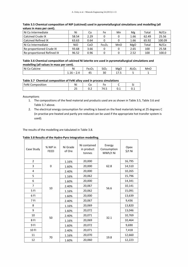
The results of the modelling are tabulated in Table 3.8. Table 3.8 Results of the Hydro-Pyro Integration modelling.
Case Study % NIP in FEED
Ni Grade of Ore
Ni contained in product
tonnes
Energy Consumption
MWh/t Ni
Opex $/t Ni
2 0
1.16% 20,000 62.8
16,795 3 1.60% 20,000 14,510 4 2.40% 20,000 10,265 5
10
1.16% 20,062
56.6
15,796 6 1.60% 20,000 14,341 7 2.40% 20,067 10,141
5 FI 1.16% 20,062 15,091 6 FI 1.60% 20,000 13,639 7 FI 2.40% 20,067 9,436
8
50
1.16% 20,069
32.1
13,820 9 1.60% 20,072 13,046
10 2.40% 20,071 10,769 8 FI 1.16% 20,069 10,464 9 FI 1.60% 20,072 9,690
10 FI 2.40% 20,071 7,418 11
70 1.16% 20,070 19.8
12,660 12 1.60% 20,060 12,223
A. Oxley et al. / Minerals Engineering 54 (2013) 2–13
Case Study % NIP in FEED
Ni Grade of Ore
Ni contained in product
tonnes
Energy Consumption
MWh/t Ni
Opex $/t Ni
13 2.40% 20,052 10,842 11 FI 1.16% 20,070 8,173 12 FI 1.60% 20,060 7,728 13 FI 2.40% 20,052 6,351
14 100 N/A
20,020 1.3
10,723 14 FI 20,020 4,882
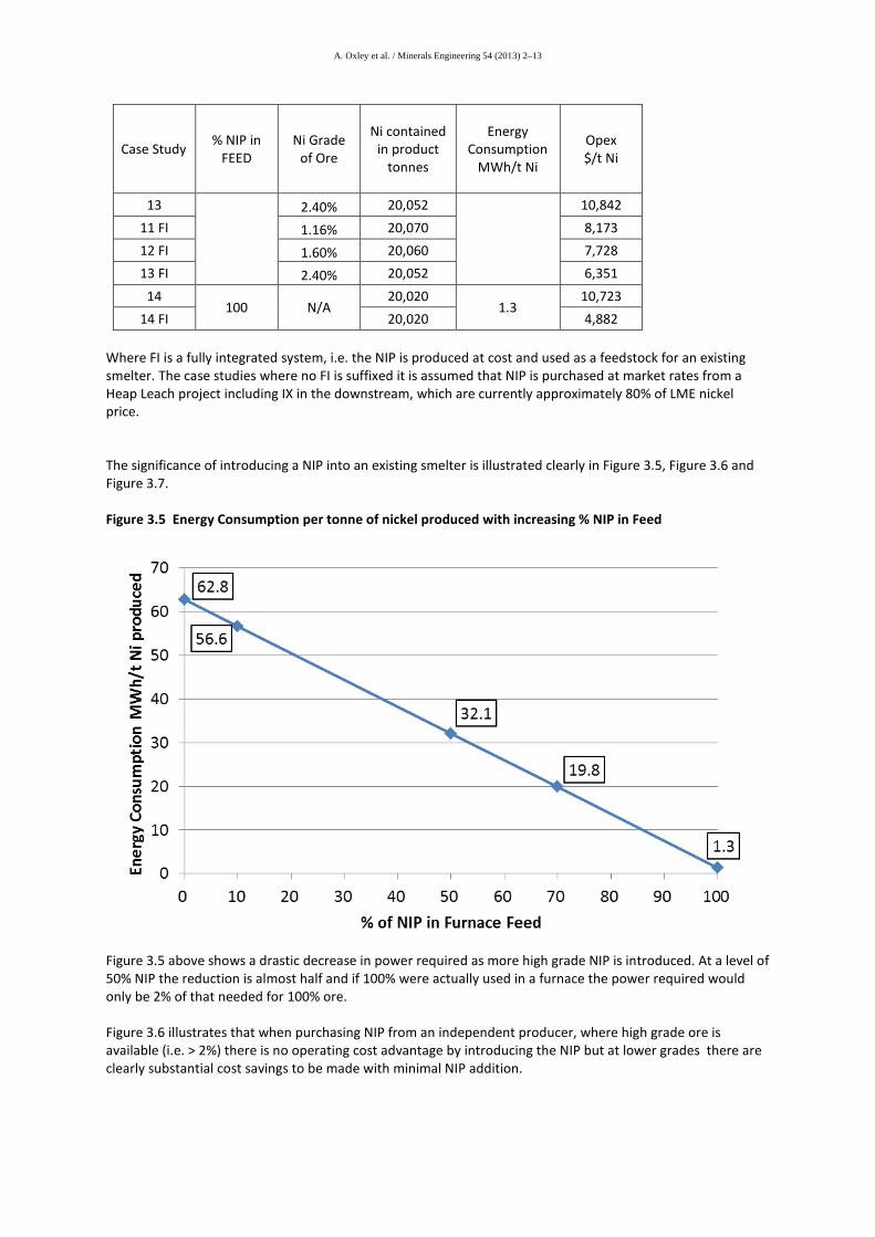
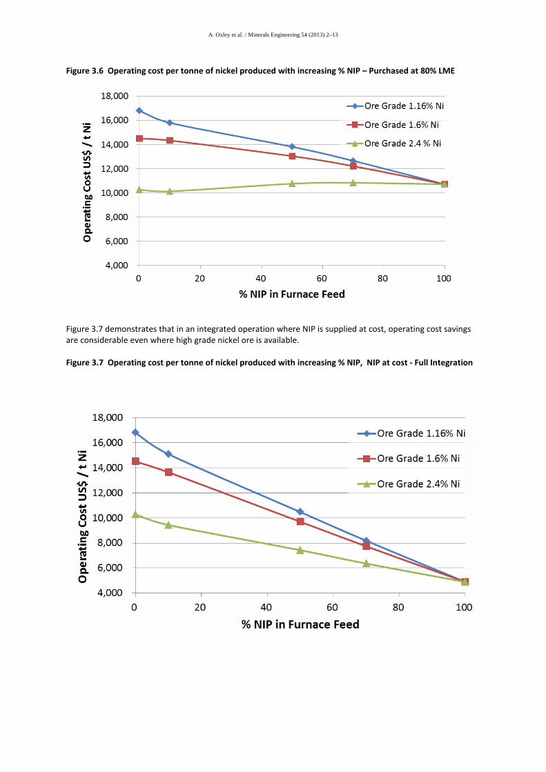
Where FI is a fully integrated system, i.e. the NIP is produced at cost and used as a feedstock for an existing smelter. The case studies where no FI is suffixed it is assumed that NIP is purchased at market rates from a Heap Leach project including IX in the downstream, which are currently approximately 80% of LME nickel price. The significance of introducing a NIP into an existing smelter is illustrated clearly in Figure 3.5, Figure 3.6 and Figure 3.7. Figure 3.5 Energy Consumption per tonne of nickel produced with increasing % NIP in Feed
Figure 3.5 above shows a drastic decrease in power required as more high grade NIP is introduced. At a level of 50% NIP the reduction is almost half and if 100% were actually used in a furnace the power required would only be 2% of that needed for 100% ore. Figure 3.6 illustrates that when purchasing NIP from an independent producer, where high grade ore is available (i.e. > 2%) there is no operating cost advantage by introducing the NIP but at lower grades there are clearly substantial cost savings to be made with minimal NIP addition.
A. Oxley et al. / Minerals Engineering 54 (2013) 2–13
Figure 3.6 Operating cost per tonne of nickel produced with increasing % NIP – Purchased at 80% LME
Figure 3.7 demonstrates that in an integrated operation where NIP is supplied at cost, operating cost savings are considerable even where high grade nickel ore is available. Figure 3.7 Operating cost per tonne of nickel produced with increasing % NIP, NIP at cost - Full Integration
A. Oxley et al. / Minerals Engineering 54 (2013) 2–13
4 Economics of Selected Case Studies
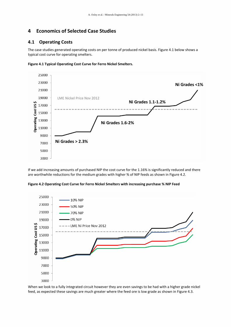
4.1 Operating Costs The case studies generated operating costs on per tonne of produced nickel basis. Figure 4.1 below shows a typical cost curve for operating smelters. Figure 4.1 Typical Operating Cost Curve for Ferro Nickel Smelters.
If we add increasing amounts of purchased NIP the cost curve for the 1.16% is significantly reduced and there are worthwhile reductions for the medium grades with higher % of NIP feeds as shown in Figure 4.2. Figure 4.2 Operating Cost Curve for Ferro Nickel Smelters with increasing purchase % NIP Feed
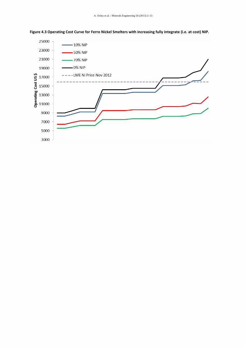
When we look to a fully integrated circuit however they are even savings to be had with a higher grade nickel feed, as expected these savings are much greater where the feed ore is low grade as shown in Figure 4.3.
LME Nickel Price Nov 2012
Ni Grades > 2.3%
Ni Grades 1.6-2%
Ni Grades 1.1-1.2%
Ni Grades <1%
A. Oxley et al. / Minerals Engineering 54 (2013) 2–13
Figure 4.3 Operating Cost Curve for Ferro Nickel Smelters with increasing fully integrate (i.e. at cost) NIP.
A. Oxley et al. / Minerals Engineering 54 (2013) 2–13
4.2 Project Economic modelling Case Study economics have been assessed using AVL developed Excel economic models for the case studies to be assessed. In this case the numerous variables required for the model are taken from typical projects or generated by model for individual case studies. Where any data is unavailable reasonable assumptions are made. Main variables in the model relate to:
• Deposit tonnage and chemical composition – in particular Ni and Co grades • Mining Parameters and unit costs • Metallurgical parameters (acid consumption, metal extractions, plant recovery, reagent usage) • Basic costs such as diesel price, electricity purchase/sales price • Adjustments for distances to water, limestone and customers • Infrastructure development needs
NB Labour rate adjustments are not used as productivity and labour rates are considered inversely proportional. The estimate is based on AVL’s internal database for revenue calculations, project capital and operating costs, modified for the conditions at site. The cash flow is then calculated from an Excel spreadsheet model. The principal assumptions of the evaluation are:
• Annual nickel production 20,000 tonnes per year of nickel in NIP • Leach rate 12 months • Ni extraction 80% from the heaps • Co extraction 75% from the heaps • HL Downstream Plant Recovery 95% • Acid Consumption 400 kg/tonne of ore leached (for 80% Ni extraction) • Sulphur price US$ 52.5/tonne (FOB) • Nickel price US$ 8.50 /lb
HL no IX 75% payable HL IX 80% payable Pyro product 100% payable
• Cobalt price US$ 17 / lb HL no IX 35% payable HL IX 80% payable - as separate product Pyro (Stand-alone) 0% payable Pyro product 80% payable - as separate product,
sold by the HL plant. When NIP is purchased for use in an existing smelter the assumption is that it has been produced via a HL with an IX , so at 80% payable nickel. On the above basis therefore the case studies would have the economic characteristics shown in Table 4.1 and Table 4.2. Table 4.1 gives the economics of new projects where NIP is purchased. When AVL assesses a project they would only take it further if initial economics show an Internal Rate of Return (IRR) of >20% on this basis with purchased NIP the only commercially attractive projects are case studies 1 and 14, which are a standalone heap leach with and without an Ion Exchange (IX) circuit and a smelter purchasing 100% NIP as it’s feed.

A. Oxley et al. / Minerals Engineering 54 (2013) 2–13
Table 4.2 presents the economics for a fully integrated project where the NIP feed to a furnace is supplied at cost. Based on AVL’s criteria for a commercially successful project case studies 1 and 14 now show excellent economics with CS 13, high grade nickel with a 70% NIP feed, exhibiting acceptable economics. There are other cases that would be profitable at the long term nickel price of US$ 8.50 /lb but the economics for these are marginal and payback time for capital expenditure lengthy.
A. Oxley et al. / Minerals Engineering 54 (2013) 2–1
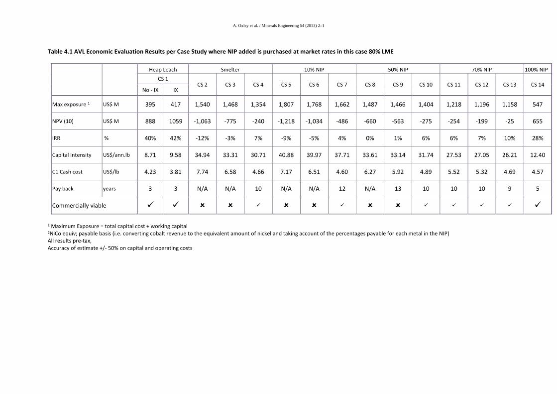
Table 4.1 AVL Economic Evaluation Results per Case Study where NIP added is purchased at market rates in this case 80% LME
Heap Leach Smelter 10% NIP 50% NIP 70% NIP 100% NIP CS 1
CS 2 CS 3 CS 4 CS 5 CS 6 CS 7 CS 8 CS 9 CS 10 CS 11 CS 12 CS 13 CS 14 No - IX IX
Max exposure 1 US$ M 395 417 1,540 1,468 1,354 1,807 1,768 1,662 1,487 1,466 1,404 1,218 1,196 1,158 547
NPV (10) US$ M 888 1059 -1,063 -775 -240 -1,218 -1,034 -486 -660 -563 -275 -254 -199 -25 655
IRR % 40% 42% -12% -3% 7% -9% -5% 4% 0% 1% 6% 6% 7% 10% 28%
Capital Intensity US$/ann.lb 8.71 9.58 34.94 33.31 30.71 40.88 39.97 37.71 33.61 33.14 31.74 27.53 27.05 26.21 12.40
C1 Cash cost US$/lb 4.23 3.81 7.74 6.58 4.66 7.17 6.51 4.60 6.27 5.92 4.89 5.52 5.32 4.69 4.57
Pay back years 3 3 N/A N/A 10 N/A N/A 12 N/A 13 10 10 10 9 5
Commercially viable
1 Maximum Exposure = total capital cost + working capital 2NiCo equiv; payable basis (i.e. converting cobalt revenue to the equivalent amount of nickel and taking account of the percentages payable for each metal in the NIP) All results pre-tax, Accuracy of estimate +/- 50% on capital and operating costs

A. Oxley et al. / Minerals Engineering 54 (2013) 2–1
Table 4.2 AVL Economic Evaluation Results per Case Study where NIP added fully integrated
Heap Leach Smelter 10% NIP 50% NIP 70% NIP 100% NIP CS 1
CS 2 CS 3 CS 4 CS 5 CS 6 CS 7 CS 8 CS 9 CS 10 CS 11 CS 12 CS 13 CS 14 No - IX IX
Max exposure 1 US$ M 395 417 1,540 1,468 1,354 1,788 1,749 1,643 1,396 1,375 1,313 850 818 780 474
NPV (10) US$ M 888 1059 -1,063 -775 -240 -1,129 -945 -397 -236 -139 149 373 426 602 1309
IRR % 40% 42% -12% -3% 7% -7% -3% 5% 7% 8% 12% 17% 18% 21% 43%
Capital Intensity US$/ann.lb 8.71 9.58 34.94 33.31 30.71 40.44 39.54 37.28 31.55 31.09 29.69 19.21 18.53 17.65 10.75
C1 Cash cost US$/lb 4.23 3.81 7.74 6.58327 4.65723 6.85 6.19 4.28 4.75 4.40 3.37 3.71 3.51 2.88 2.22
Pay back years 3 3 N/A N/A 10 N/A N/A 11 10 10 8 7 7 6 3
Commercially viable 1 Maximum Exposure = total capital cost + working capital 2NiCo equiv; payable basis (i.e. converting cobalt revenue to the equivalent amount of nickel and taking account of the percentages payable for each metal in the NIP) All results pre-tax, Accuracy of estimate +/- 50% on capital and operating costs .
A. Oxley et al. / Minerals Engineering 54 (2013) 2–1
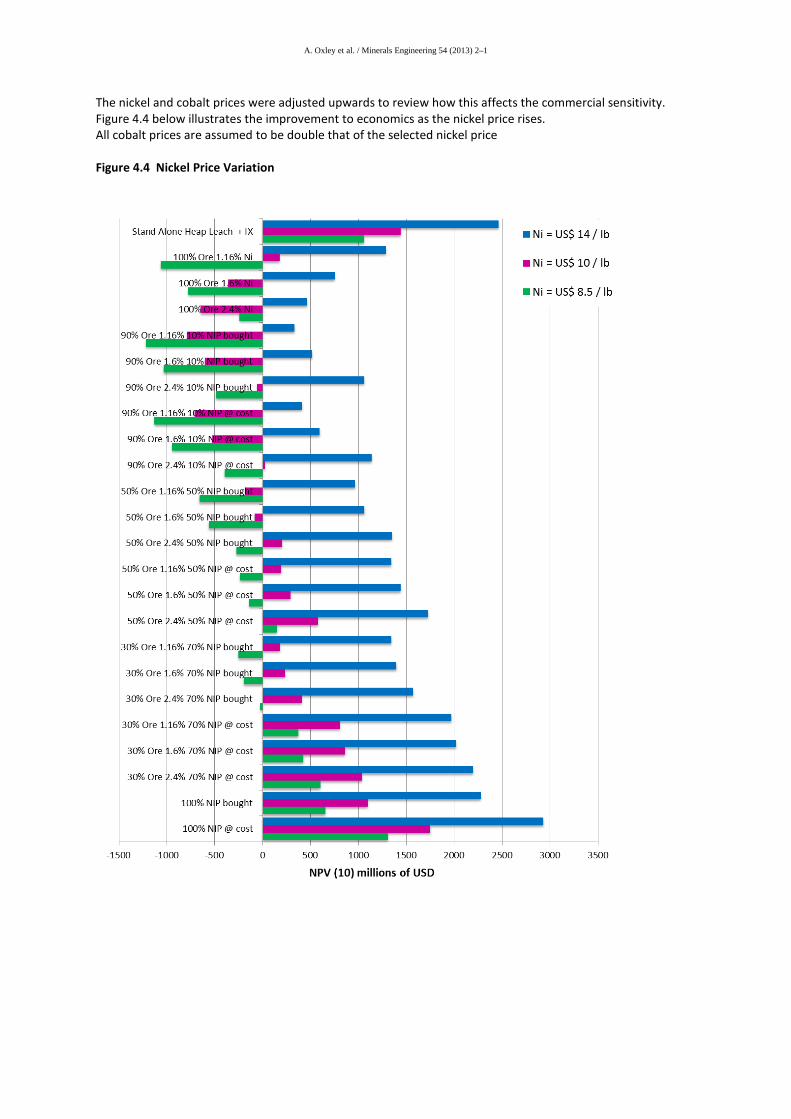
The nickel and cobalt prices were adjusted upwards to review how this affects the commercial sensitivity. Figure 4.4 below illustrates the improvement to economics as the nickel price rises. All cobalt prices are assumed to be double that of the selected nickel price Figure 4.4 Nickel Price Variation
A. Oxley et al. / Minerals Engineering 54 (2013) 2–1
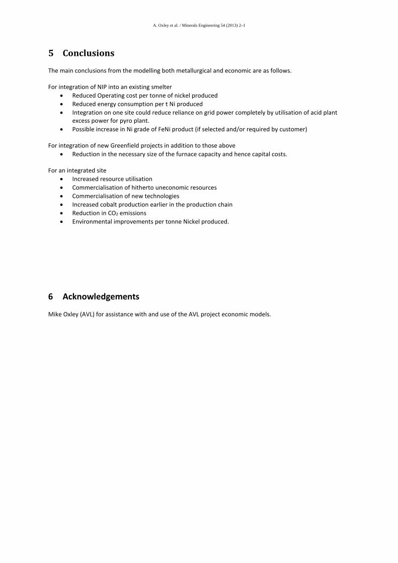
5 Conclusions
The main conclusions from the modelling both metallurgical and economic are as follows. For integration of NIP into an existing smelter
• Reduced Operating cost per tonne of nickel produced • Reduced energy consumption per t Ni produced • Integration on one site could reduce reliance on grid power completely by utilisation of acid plant
excess power for pyro plant. • Possible increase in Ni grade of FeNi product (if selected and/or required by customer)
For integration of new Greenfield projects in addition to those above
• Reduction in the necessary size of the furnace capacity and hence capital costs. For an integrated site
• Increased resource utilisation • Commercialisation of hitherto uneconomic resources • Commercialisation of new technologies • Increased cobalt production earlier in the production chain • Reduction in CO2 emissions • Environmental improvements per tonne Nickel produced.
6 Acknowledgements
Mike Oxley (AVL) for assistance with and use of the AVL project economic models.
A. Oxley et al. / Minerals Engineering 54 (2013) 2–1
7 References
1. A.D. Dalvi, W.G. Bacon and R.C. Osborne, “The past and future of nickel latertites”, PDAC 2004 International Convention, March 7-10, 2004, pp 1-27. Available online: http://www.pdac.ca/pdac/publications/papers/2004/techprgm-dalvi-bacon.pdf
2. Brand, N.W., C.R.M. Butt, and M. Elias, Nickel Laterites: Classification and Features. AGSO Journal of Australian Geology & Geophysics, 1998.
3. A.Taylor, M.L. Jansen, “Future trends in PAL plant design for Ni/Co laterites”, in Ni/Co2000, ALTA Metallurgical Services, Melbourne, pp 1-13. Available online: http://www.altamet.com.au/Technical%20Papers%20and%20Articles/ALTA%20Ni- Co/Future%20Trends%20in%20PAL%20Plant%20Design.pdf
4. B Willis M Goiny “A Global Engineer’s Perspective on Nickel HPAL Technology” Australian Journal of Mining, "The Return of Nickel Laterite” Conference, September 2005
5. M G King “Nickel Laterite Technology – Finally a new dawn” 2005 JOM 6. CRU – 2011 Nickel project overview (Industry study) 7. Brooke Hunt “Nickel Industry Cost Study” 2010 edition 8. Reid, J. and S. Barnett, Nickel Laterite Hydrometallurgical Processing Update, in ALTA
2002 Nickel/Cobalt 8. 2002, 9. Taylor, A., Nickel Processing Technology-10 years on from Cawse, Bulong and
Murrin Murrin, in ALTA 2007 Nickel/Cobalt Conference. 2007, ALTA Metallurgical Services: Perth, Australia.
10. Jones, R.T. Pyrosim http://www.mintek.co.za/Pyromet/Pyrosim/Pyrosim2.htm 11. Naudé, C.P. * and Shapiro,M.D. * Implementation of the first commercial scale DC smelter
for ferronickel production from low grade laterite ores—technology building blocks and lessons learned, The Journal of The Southern African Institute of Mining and Metallurgy Dec. 2010 Vol. 110 pp 725 732, http://www.saimm.co.za/Journal/v110n12p725.pdf
Highlights
1. Hydro-pyro Integration of nickel laterite processing 2. Global Nickel Laterite Production 3. Existing & Advances to State of the Art of Hydrometallurgical and Pyrometallurgical Nickel laterite
processing 4. Hydro-Pyro integration Flow sheet options and Case Studies 5. Economics of Selected Case Studies