Tapered Navigator System For Guided Surgery - Biometbiomet3i.com/FMEA/Tapered Navigator System...
36
Procedure And Laboratory Manual Tapered Navigator ® System For Guided Surgery
Transcript of Tapered Navigator System For Guided Surgery - Biometbiomet3i.com/FMEA/Tapered Navigator System...
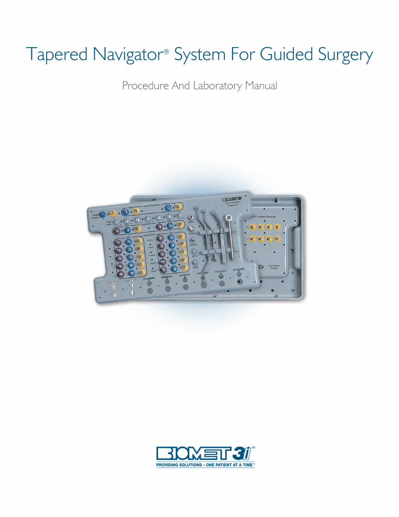
Procedure And Laboratory Manual
Tapered Navigator® System For Guided Surgery

BIOMET 3i Tapered Navigator® System: Steps To Success . . . . . . . . . . . . . . . . . . . . . . . . . . . . . . . . . . . . . 1
Getting Started . . . . . . . . . . . . . . . . . . . . . . . . . . . . . . . . . . . . . . . . . . . . . . . . . . . . . . . . . . . . . . . . . . . . . . . . . . 3
Introduction And Treatment Planning . . . . . . . . . . . . . . . . . . . . . . . . . . . . . . . . . . . . . . . . . . . . . . . . . . . . . . 4
Instrumentation Overview . . . . . . . . . . . . . . . . . . . . . . . . . . . . . . . . . . . . . . . . . . . . . . . . . . . . . . . . . . . . . . . . 5
Surgical Plan Overview . . . . . . . . . . . . . . . . . . . . . . . . . . . . . . . . . . . . . . . . . . . . . . . . . . . . . . . . . . . . . . . . . . 10
Tips And Techniques . . . . . . . . . . . . . . . . . . . . . . . . . . . . . . . . . . . . . . . . . . . . . . . . . . . . . . . . . . . . . . . . . . . . 12
Immediate Provisionalization Option . . . . . . . . . . . . . . . . . . . . . . . . . . . . . . . . . . . . . . . . . . . . . . . . . . . . . . 14
Fabrication Of A New Denture Or Partial Denture And CT Scanning Appliance . . . . . . . . . . . . . . . . . 15
Fabrication Of A CT Scanning Appliance Using An Existing Denture . . . . . . . . . . . . . . . . . . . . . . . . . . . 17
Pre-Surgical Fabrication Of An Edentulous Fixed Provisional Restoration
Fabrication Of Master Cast, Articulation And Vacuum Formed Template . . . . . . . . . . . . . . . . . . . . . . . . . . . . . 18
Screw-Retained PreFormance® Temporary Cylinder . . . . . . . . . . . . . . . . . . . . . . . . . . . . . . . . . . . . . . . . . . . 19
Screw-Retained Low Prof ile Abutment And Temporary Cylinder . . . . . . . . . . . . . . . . . . . . . . . . . . . . . . . . . . 21
Combination Cement/Screw-Retained QuickBridge® Restoration And Low Prof ile Temporary Cylinder . . . . 23
Pre-Surgical Fabrication Of A Partially Edentulous Fixed Provisional Restoration
Fabrication Of Master Cast, Articulation And Vacuum Formed Template . . . . . . . . . . . . . . . . . . . . . . . . . . . . 26
Cement-Retained PreFormanc,m e Post . . . . . . . . . . . . . . . . . . . . . . . . . . . . . . . . . . . . . . . . . . . . . . . . . . . . 27
Cement-Retained Provide® Abutment And Temporary Cylinder . . . . . . . . . . . . . . . . . . . . . . . . . . . . . . . . . . 29
Table Of Contents
1
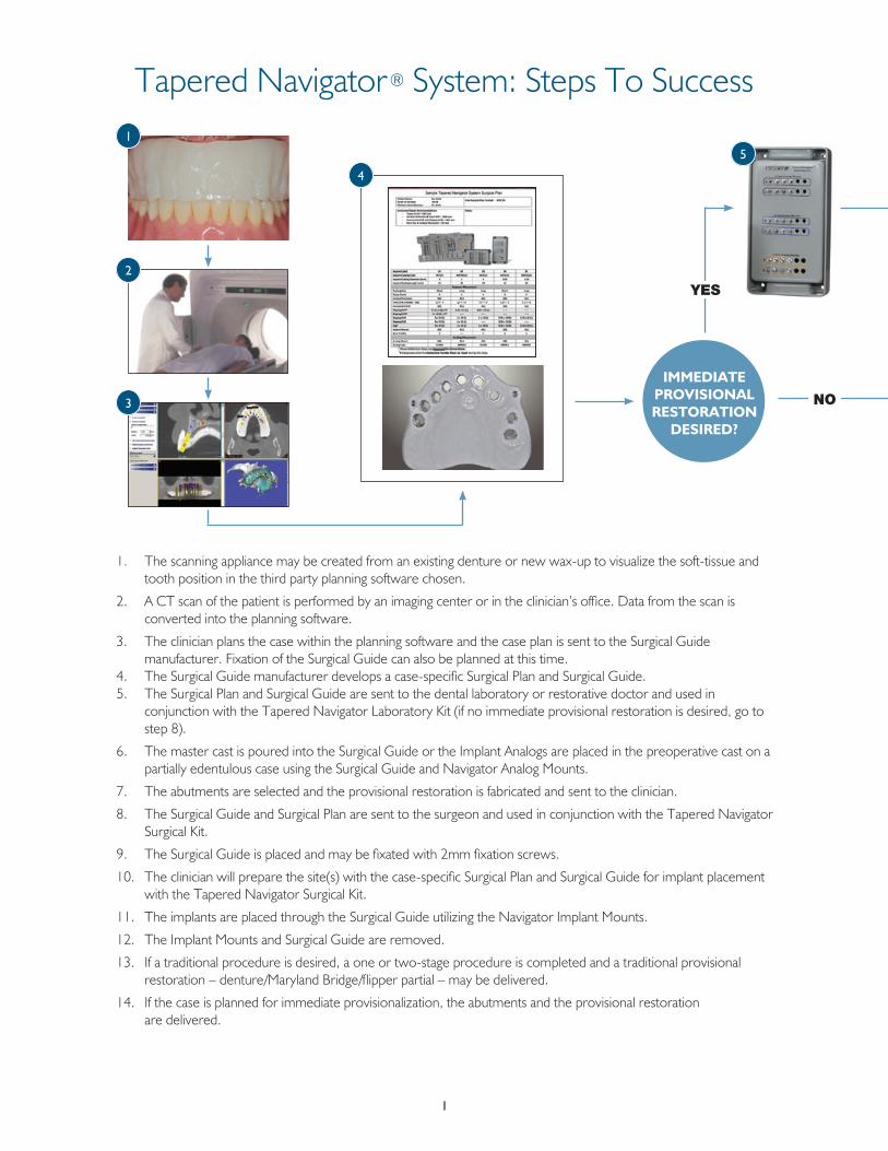
1 . The scanning appliance may be created from an existing denture or new wax-up to visualize the soft-tissue and tooth position in the third party planning software chosen .
2 . A CT scan of the patient is performed by an imaging center or in the clinician’s office . Data from the scan is converted into the planning software .
3 . The clinician plans the case within the planning software and the case plan is sent to the Surgical Guide manufacturer . Fixation of the Surgical Guide can also be planned at this time .
4 . The Surgical Guide manufacturer develops a case-specific Surgical Plan and Surgical Guide . 5 . The Surgical Plan and Surgical Guide are sent to the dental laboratory or restorative doctor and used in
conjunction with the Tapered Navigator Laboratory Kit (if no immediate provisional restoration is desired, go to step 8) .
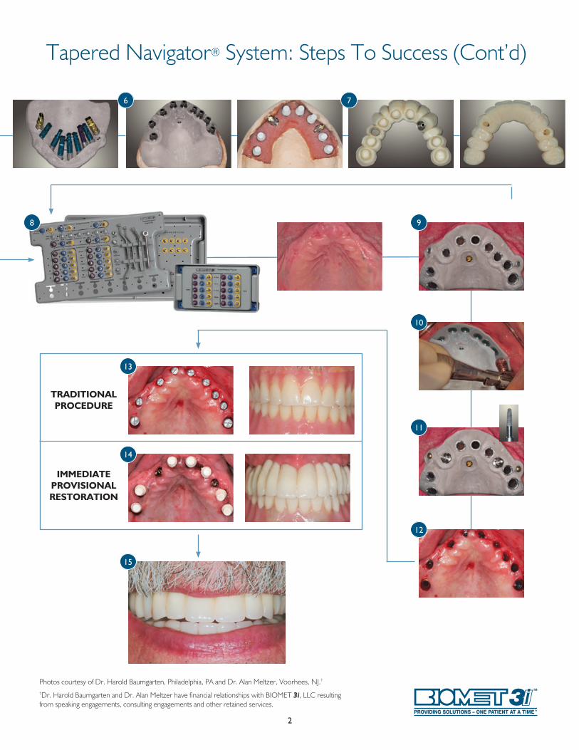
6 . The master cast is poured into the Surgical Guide or the Implant Analogs are placed in the preoperative cast on a partially edentulous case using the Surgical Guide and Navigator Analog Mounts .
7 . The abutments are selected and the provisional restoration is fabricated and sent to the clinician .
8 . The Surgical Guide and Surgical Plan are sent to the surgeon and used in conjunction with the Tapered Navigator Surgical Kit .
9 . The Surgical Guide is placed and may be fixated with 2mm fixation screws .
10 . The clinician will prepare the site(s) with the case-specific Surgical Plan and Surgical Guide for implant placement with the Tapered Navigator Surgical Kit .
11 . The implants are placed through the Surgical Guide utilizing the Navigator Implant Mounts .
12 . The Implant Mounts and Surgical Guide are removed .
13 . If a traditional procedure is desired, a one or two-stage procedure is completed and a traditional provisional restoration – denture/Maryland Bridge/flipper partial – may be delivered .
14 . If the case is planned for immediate provisionalization, the abutments and the provisional restoration are delivered .
IMMEDIATEPROVISIONALRESTORATION
DESIRED?
Tapered Navigator® System: Steps To Success
YES
NO
1
2
3
4
5
2
Photos courtesy of Dr . Harold Baumgarten, Philadelphia, PA and Dr . Alan Meltzer, Voorhees, NJ .†
†Dr . Harold Baumgarten and Dr . Alan Meltzer have financial relationships with BIOMET 3i, LLC resulting from speaking engagements, consulting engagements and other retained services .
Tapered Navigator® System: Steps To Success (Cont’d)
TRADITIONALPROCEDURE
IMMEDIATEPROVISIONALRESTORATION
6 7
8 9
10
11
12
13
14
15
3
Getting Started
In order to utilize the BIOMET 3i Tapered Navigator® System For Guided Surgery, clinicians will need to purchase CT planning software from a planning software company and have access to a Cone Beam Scanner or a CT scanning facility . Training on how to use the CT planning software chosen is essential for all clinicians and technicians involved in case treatment planning . In addition, laboratory technicians will need to obtain the Tapered Navigator Laboratory Kit to fabricate the preoperative master cast and clinicians will need to obtain the Tapered Navigator Surgical Kit to perform guided implant placement . The complete system overview that describes each instrument and component included in the kits and their associated use begins on page 5 .
Prior to CT scanning of the patient, a radiopaque scanning appliance may be fabricated to show the desired tooth position of the restoration when seated in the mouth during the CT scan . Pages 15-17 of this manual are designed to guide surgeons, restorative clinicians and laboratory technicians through the process of fabricating a scanning appliance from an existing denture, a newly fabricated denture or a diagnostic wax up .
A page with tips from clinicians who evaluated the system prior to market release is also included in this manual on pages 12-13 . The tips help to ensure a smooth process from CT scan to the day of surgery and provisional restoration delivery, which may reduce the learning curve associated with use of the Tapered Navigator System For Guided Surgery .
Open Architecture SystemThe Tapered Navigator System For Guided Surgery is designed to allow clinicians to place and provisionalize BIOMET 3i Dental Implants using a variety of compatible CT planning software and Surgical Guides . The system is open architecture compatible with the current software and Surgical Guide providers listed below .
Materialise Dental, Inc.810-X Cromwell Park DriveGlen Burnie, MD 21061United States(443) 557-0121www .materialisedental .com Materialise Dental, NVTechnologielaan 15 3001 LeuvenBelgium+32 16 39 66 20
iDent - US Headquarters1289 East Hillsdale BoulevardFoster City, CA 94404(650) 212-1701
iDent - Israel Office4 Yohanan StreetBox 6402Hod Hasharon, 45241Israel +972-54-467-5683
SICAT Gmbh & Co. KGBrunnenallee 6D-53177 BonnGermany+49-228-854-6970
4
Introduction And Treatment Planning
These instructions were designed to serve as a reference guide for dental practitioners utilizing BIOMET 3i Implants and Surgical Instruments. BIOMET 3i Designs enable the practitioner to place implants in edentulous or partially edentulous mandibles or maxillae in order to support fixed and removable bridgework or single tooth crowns and overdentures .
General Information:The success of any dental implant system depends upon proper use of the components and instrumentation . This manual is not intended for use as a substitute for professional training and experience .
Treatment Planning:Patient Evaluation And SelectionSeveral important factors must be considered when evaluating a patient prior to implant surgery . The presurgical evaluation must include a cautious and detailed assessment of the patient’s general health, current medical status, medical history, oral hygiene, motivation and expectations . Factors such as heavy tobacco use, masticatory function and alcohol consumption should also be considered . In addition, the clinician should determine if the case presents an acceptable anatomical basis conducive to implant placement . An extensive intraoral examination should be undertaken to evaluate the oral cavity for any potential bone or soft-tissue pathology . The examiner should also determine the periodontal status of the remaining teeth, the health of the soft-tissue and the presence of occlusal abnormalities such as bruxism or crossbite . The presence of other conditions that could adversely affect any existing natural dentition or healthy soft-tissue surrounding the implant should also be evaluated .
Diseases of the mucous membrane and connective tissues, pathologic bone disease and severe malocclusion could affect the determination of whether a patient is a suitable implant candidate .
The use of anticoagulants and the existence of metabolic diseases, such as diabetes, allergies, chronic renal or cardiac disease and blood dyscrasia could significantly influence the patient’s ability to successfully undergo implant procedures .
If the patient’s medical history reveals an existing condition or signals a potential problem that may compromise treatment and/or the patient’s well-being, consultation with a physician is recommended .
5
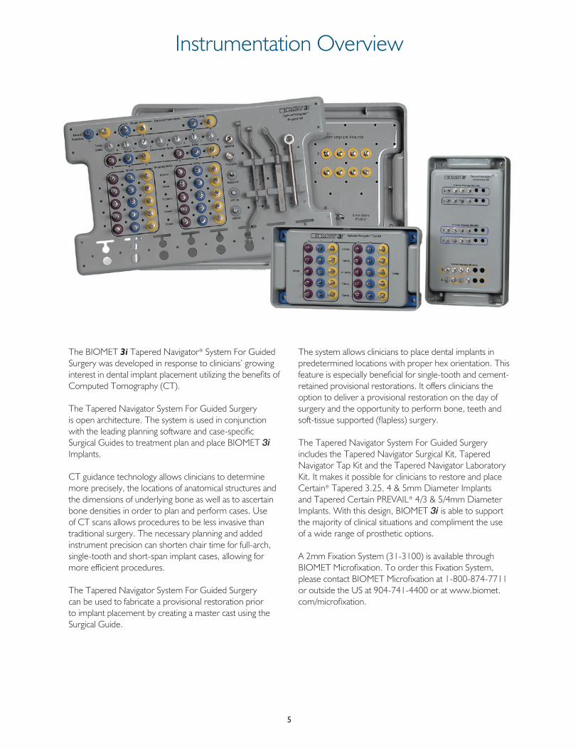
Instrumentation Overview
The BIOMET 3i Tapered Navigator® System For Guided Surgery was developed in response to clinicians’ growing interest in dental implant placement utilizing the benefi ts of Computed Tomography (CT) .
The Tapered Navigator System For Guided Surgery is open architecture . The system is used in conjunction with the leading planning software and case-specifi c Surgical Guides to treatment plan and place BIOMET 3i Implants .
CT guidance technology allows clinicians to determine more precisely, the locations of anatomical structures and the dimensions of underlying bone as well as to ascertain bone densities in order to plan and perform cases . Use of CT scans allows procedures to be less invasive than traditional surgery . The necessary planning and added instrument precision can shorten chair time for full-arch, single-tooth and short-span implant cases, allowing for more effi cient procedures .
The Tapered Navigator System For Guided Surgery can be used to fabricate a provisional restoration prior to implant placement by creating a master cast using the Surgical Guide .
The system allows clinicians to place dental implants in predetermined locations with proper hex orientation . This feature is especially benefi cial for single-tooth and cement-retained provisional restorations . It offers clinicians the option to deliver a provisional restoration on the day of surgery and the opportunity to perform bone, teeth and soft-tissue supported (fl apless) surgery .
The Tapered Navigator System For Guided Surgery includes the Tapered Navigator Surgical Kit, Tapered Navigator Tap Kit and the Tapered Navigator Laboratory Kit . It makes it possible for clinicians to restore and place Certain® Tapered 3 .25, 4 & 5mm Diameter Implants and Tapered Certain PREVAIL® 4/3 & 5/4mm Diameter Implants . With this design, BIOMET 3i is able to support the majority of clinical situations and compliment the use of a wide range of prosthetic options .
A 2mm Fixation System (31-3100) is available through BIOMET Microfi xation . To order this Fixation System, please contact BIOMET Microfi xation at 1-800-874-7711 or outside the US at 904-741-4400 or at www .biomet .com/microfi xation .
Instrumentation Overview
6
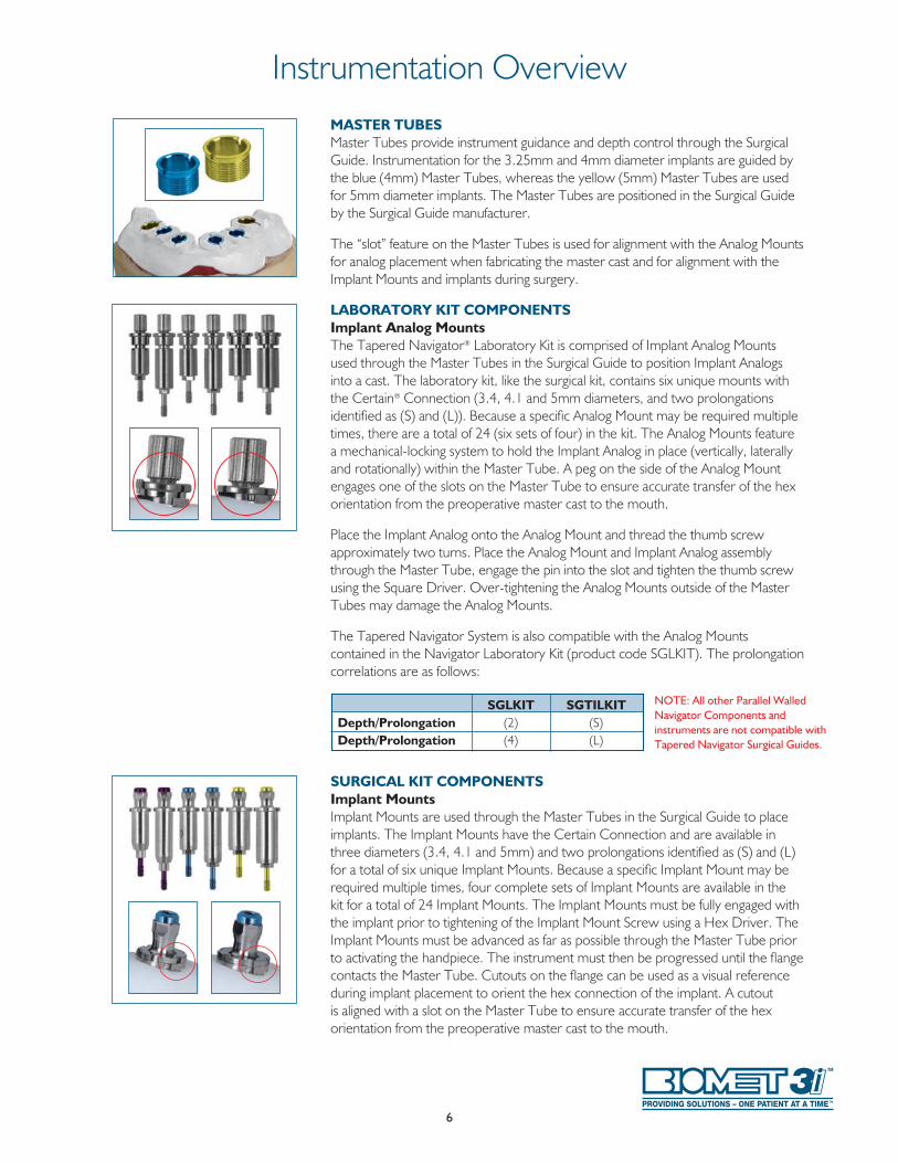
MASTER TUBES Master Tubes provide instrument guidance and depth control through the Surgical Guide . Instrumentation for the 3 .25mm and 4mm diameter implants are guided by the blue (4mm) Master Tubes, whereas the yellow (5mm) Master Tubes are used for 5mm diameter implants . The Master Tubes are positioned in the Surgical Guide by the Surgical Guide manufacturer .
The “slot” feature on the Master Tubes is used for alignment with the Analog Mounts for analog placement when fabricating the master cast and for alignment with the Implant Mounts and implants during surgery .
LABORATORY KIT COMPONENTS Implant Analog Mounts The Tapered Navigator® Laboratory Kit is comprised of Implant Analog Mounts used through the Master Tubes in the Surgical Guide to position Implant Analogs into a cast . The laboratory kit, like the surgical kit, contains six unique mounts with the Certain® Connection (3 .4, 4 .1 and 5mm diameters, and two prolongations identified as (S) and (L)) . Because a specific Analog Mount may be required multiple times, there are a total of 24 (six sets of four) in the kit . The Analog Mounts feature a mechanical-locking system to hold the Implant Analog in place (vertically, laterally and rotationally) within the Master Tube . A peg on the side of the Analog Mount engages one of the slots on the Master Tube to ensure accurate transfer of the hex orientation from the preoperative master cast to the mouth .
Place the Implant Analog onto the Analog Mount and thread the thumb screw approximately two turns . Place the Analog Mount and Implant Analog assembly through the Master Tube, engage the pin into the slot and tighten the thumb screw using the Square Driver . Over-tightening the Analog Mounts outside of the Master Tubes may damage the Analog Mounts .
The Tapered Navigator System is also compatible with the Analog Mounts contained in the Navigator Laboratory Kit (product code SGLKIT) . The prolongation correlations are as follows:
SURGICAL KIT COMPONENTS Implant Mounts Implant Mounts are used through the Master Tubes in the Surgical Guide to place implants . The Implant Mounts have the Certain Connection and are available in three diameters (3 .4, 4 .1 and 5mm) and two prolongations identified as (S) and (L) for a total of six unique Implant Mounts . Because a specific Implant Mount may be required multiple times, four complete sets of Implant Mounts are available in the kit for a total of 24 Implant Mounts . The Implant Mounts must be fully engaged with the implant prior to tightening of the Implant Mount Screw using a Hex Driver . The Implant Mounts must be advanced as far as possible through the Master Tube prior to activating the handpiece . The instrument must then be progressed until the flange contacts the Master Tube . Cutouts on the flange can be used as a visual reference during implant placement to orient the hex connection of the implant . A cutout is aligned with a slot on the Master Tube to ensure accurate transfer of the hex orientation from the preoperative master cast to the mouth .
SGLKIT SGTILKITDepth/Prolongation (2) (S)Depth/Prolongation (4) (L)
NOTE: All other Parallel Walled Navigator Components and instruments are not compatible with Tapered Navigator Surgical Guides.
7
Instrumentation Overview
TISSUE PUNCHES Tissue Punches are used through the Master Tubes in the Surgical Guide (until bone contact occurs) to remove soft-tissue for flapless surgery . Tissue Punches are available in two diameters (4 and 5mm) and one length . Each Tissue Punch accommodates two prolongations . The (S) prolongation is designated by the laser line, with the top of the Tissue Punch representing (L) . Depending on the planned placement of the implant (i .e ., subcrestal), these references may not coincide with the top of the Master Tube . Discontinue use of the instrument once the cutting edge of the Tissue Punch makes bone contact .
The recommended drill speed is 300rpm .
CORTICAL PERFORATORS Cortical Perforators are used through the Master Tubes in the Surgical Guide to perforate the cortical plate . The Cortical Perforators are available in two diameters (4 and 5mm) and two prolongations (S and L) . The Cortical Perforators must be advanced as far as possible so that the guide body is engaged within the Master Tube prior to activation . The “guide body” refers to the cylindrical portion of the instrument, which is guided by the Master Tube . The Cortical Perforators must then be progressed until the flange contacts the Master Tube .
The recommended drill speed is 1200rpm .
TWIST DRILLS Twist Drills are used to prepare the osteotomy for implant placement . Once the Surgical Guide is in place, the Twist Drill with the Twist Drill Positioning Handle is inserted into the Master Tubes of the Surgical Guide . The Twist Drills are to be inserted as far as possible through the Drill Positioning Handle into the osteotomy prior to activation . The drills are depth-specific with no depth lines and contain flanges to stop the drills when these make contact with the Twist Drill Positioning Handle . Twist Drills are available in one diameter (1 .9mm) and seven lengths (a, b, c, d, e, f and g) .
The recommended drill speed is 1200rpm .
Instrumentation Overview
8
TWIST DRILL POSITIONING HANDLE The Twist Drill Positioning Handle contains two Drill Guide Tubes (4 and 5mm) that are placed within the respective Master Tubes of the Surgical Guide to guide and stop the Twist Drills at a predetermined depth for preparation of the osteotomy . The Twist Handle must be fully seated within the corresponding Master Tube prior to Twist Drill engagement .
COUNTERSINK DRILLS Countersink Drills are available in three diameters (3, 4 and 5mm) and two prolongations (S and L) . The Countersink Drills must be advanced as far as possible so that the guide body is engaged within the Master Tube prior to activation . The Countersink Drills must then be progressed until the flange contacts the Master Tube .
The recommended drill speed is 800rpm .
SHAPING DRILLS Shaping Drills are available in three diameters (3 .25, 4 and 5mm), two prolongations (S and L) and five lengths (8 .5, 10, 11 .5, 13 and 15mm) . In some instances, as specified in the Surgical Plan (for 5mm implants in dense bone), the 4mm diameter Shaping Drills will be used in conjunction with a Reduction Handle . The Shaping Drills must be advanced as far as possible so that the guide body of the drill is engaged within the Master Tube and/or Reduction Handle prior to activation . The instrument must then be progressed until the flange contacts the Master Tube and/or Reduction Handle .
The recommended drill speed is 800rpm .
9
REDUCTION DRILL POSITIONING HANDLE The Reduction Drill Positioning Handle contains one Drill Guide Tube that fits into the 5mm diameter Master Tube and is used with 4mm diameter Shaping Drills for dense bone . The Reduction Handle must be fully seated within the Master Tube prior to Shaping Drill engagement .
BONE TAPS The Bone Taps are available in three diameters (3 .25, 4 and 5mm), two prolongations (S and L), and five lengths (8 .5, 10, 11 .5, 13, and 15mm) . The Bone Taps must be advanced as far as possible through the Master Tube prior to activation . The instrument must then be progressed until the flange contacts the Master Tube .
The recommended drill speed is 20rpm .
IMPLANT STAGING The Tapered Navigator® Surgical Kit contains eight implant holder slots to receive the inner packaging of BIOMET 3i Tapered Implants, similar to existing surgical kits . Implants will be manually pre-mounted here in preparation for placement .
BONE PROFILERS Hand-held Bone Profilers are available to manually remove crestal bone for proper abutment seating after the Surgical Guide is removed for 3 .4, 4 .1 and 5mm diameter implants .
MISCELLANEOUS TOOLS Miscellaneous standard drivers and ratchets are included in the system to place BIOMET 3i Implants . These tools include the following: PHD02N, RASH3N, MDR10, CW100, WR150, RE100 and RE200 .
Instrumentation Overview
10
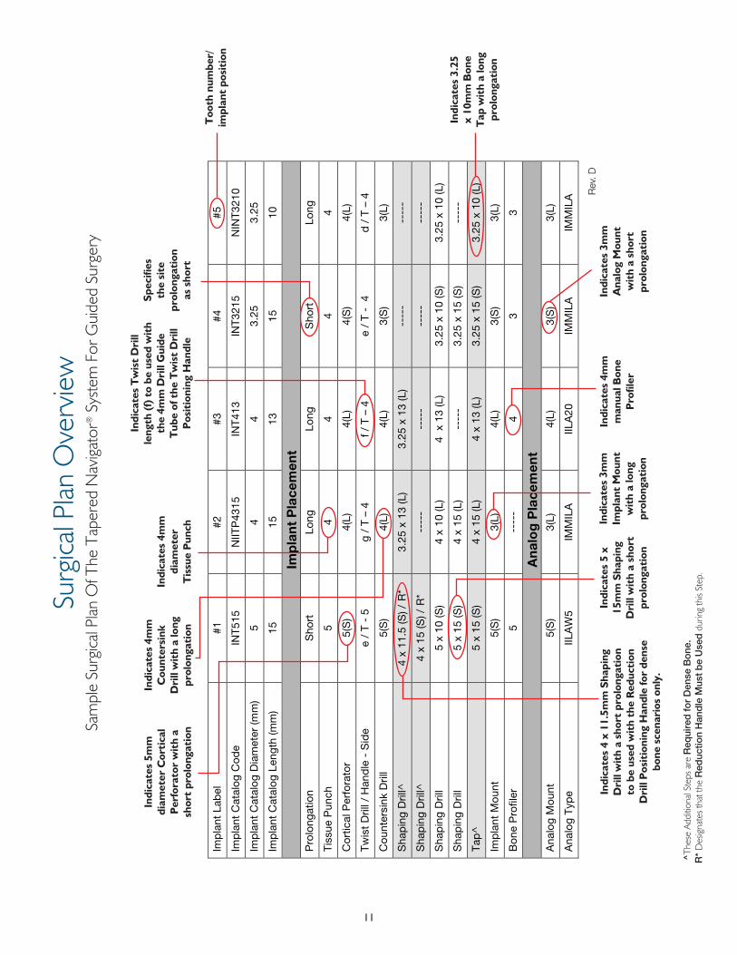
The BIOMET 3i Tapered Navigator® System For Guided Surgery works in conjunction with the Surgical Plan, which is provided by the CT planning software company and/or the Surgical Guide manufacturer . Each Surgical Plan is case-specific to provide direction regarding the instrumentation that will be used for each implant site, including the additional steps required for dense bone and the instrument speed recommendations .
The prolongation, defined as the vertical relationship between the implant platform and Master Tube, is determined for each implant site by the Surgical Guide manufacturer . The Tapered Navigator System For Guided Surgery has two prolongations: Short and Long or (S) and (L) .
The Surgical Plan specifies the prolongation (S and L) for instruments that pass directly through the Surgical Guide Master Tubes including the Tissue Punches, Cortical Perforators, Countersink Drills, Shaping Drills and Bone Taps . The Tissue Punches have landmarks referenced as (S) and (L) that indicate the approximate depth to which this instrument should be used through the Master Tubes (Figure 1) . The Tissue Punches pass through the Master Tube until the center of the specified line on the instrument reaches the top of the Master Tube (Figure 2) . Depending on the planned placement of the implant (i .e ., subcrestal), these references may not coincide with the top of the Master Tube . Discontinue use of the instrument once the cutting edge of the Tissue Punch makes bone contact . All other instruments that pass through the guide are progressed until the flange contacts the Master Tube .
The prolongation also determines which Implant Mount and Implant Analog Mount must be used . These are labeled by diameter and prolongation . Therefore, a 4mm implant with a short prolongation will be specified as 4(S) .
The Tapered Navigator System is also compatible with the Analog Mounts contained in the Navigator Laboratory Kit (product code SGLKIT) . The prolongation correlations are as follows:
NOTE: All other Parallel Walled Navigator Components and instruments are not compatible with Tapered Navigator Surgical Guides.
Surgical Plan Overview
Figure 2
Figure 1
S
L
SGLKIT SGTILKITDepth/Prolongation (2) (S)Depth/Prolongation (4) (L)
11
Surg
ical P
lan O
verv
iew
Sam
ple
Surg
ical P
lan O
f The
Tap
ered
Nav
igat
or® S
yste
m F
or G
uide
d Su
rger
y
Indi
cate
s 5m
m
diam
eter
Cor
tica
l P
erfo
rato
r w
ith
a sh
ort
prol
onga
tion
Indi
cate
s 4m
m
Cou
nter
sink
D
rill
wit
h a
long
pr
olon
gati
on
Indi
cate
s 4
x 11
.5m
m S
hapi
ng
Dri
ll w
ith
a sh
ort
prol
onga
tion
to
be
used
wit
h th
e R
educ
tion
D
rill
Pos
itio
ning
Han
dle
for
dens
e bo
ne s
cena
rios
onl
y.
Indi
cate
s T
wis
t D
rill
leng
th (
f) t
o be
use
d w
ith
the
4mm
Dri
ll G
uide
T
ube
of t
he T
wis
t D
rill
Pos
itio
ning
Han
dle
Indi
cate
s 4m
m
diam
eter
T
issu
e P
unch
Spec
ifies
th
e si
te
prol
onga
tion
as
sho
rt
Too
th n
umbe
r/im
plan
t po
siti
on
Indi
cate
s 5
x 15
mm
Sha
ping
D
rill
wit
h a
shor
t pr
olon
gati
on
Indi
cate
s 3m
m
Impl
ant
Mou
nt
wit
h a
long
pr
olon
gati
on
Indi
cate
s 4m
m
man
ual B
one
Pro
filer
Indi
cate
s 3m
m
Ana
log
Mou
nt
wit
h a
shor
t pr
olon
gati
on
Indi
cate
s 3.
25
x 10
mm
Bon
e T
ap w
ith
a lo
ng
prol
onga
tion
^Th
ese
Addi
tiona
l Ste
ps a
re R
equi
red
for
Den
se B
one
.R
* D
esig
nate
s tha
t the
Red
uctio
n H
and
le M
ust
be
Use
d d
urin
g th
is St
ep .
12
Tips And Techniques
PLANNING Surgical Guide f ixation is required for tissue-supported cases and recommended for tooth and bone-supported cases to minimize Surgical Guide movement during surgery . 2mm bone screws assist with the stabilization of the Surgical Guide . Points of f ixation can be planned into a Surgical Guide during treatment planning within the software .
Consider interarch space when planning implant lengths in the posterior . All systems that utilize Surgical Guides will require long drills to accommodate the additional vertical length required to pass through the Surgical Guide and soft-tissue .
When planning implant placement within the planning software, an additional length of 0 .6mm beyond the apex of the implant must be included to accommodate for the additional length of the Twist and Shaping Drill Tips .
PREPARATION Review the Surgical Plan and identify the respective instruments within each kit prior to surgery . Be aware of the specified prolongation, (S) or (L) . Prolongation is defined as the vertical relationship between the implant platform and the Master Tube .
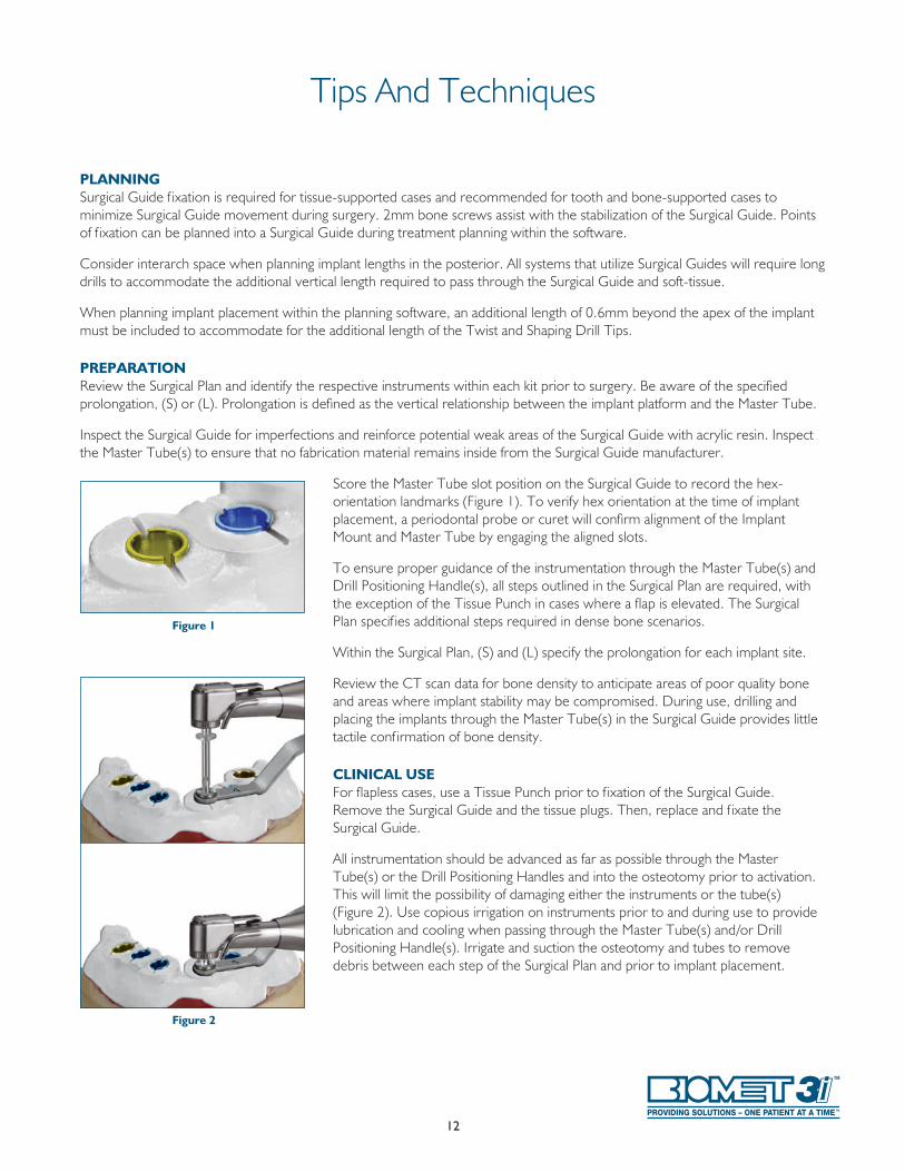
Inspect the Surgical Guide for imperfections and reinforce potential weak areas of the Surgical Guide with acrylic resin . Inspect the Master Tube(s) to ensure that no fabrication material remains inside from the Surgical Guide manufacturer .
Score the Master Tube slot position on the Surgical Guide to record the hex-orientation landmarks (Figure 1) . To verify hex orientation at the time of implant placement, a periodontal probe or curet will confirm alignment of the Implant Mount and Master Tube by engaging the aligned slots .
To ensure proper guidance of the instrumentation through the Master Tube(s) and Drill Positioning Handle(s), all steps outlined in the Surgical Plan are required, with the exception of the Tissue Punch in cases where a flap is elevated . The Surgical Plan specif ies additional steps required in dense bone scenarios .
Within the Surgical Plan, (S) and (L) specify the prolongation for each implant site .
Review the CT scan data for bone density to anticipate areas of poor quality bone and areas where implant stability may be compromised . During use, drilling and placing the implants through the Master Tube(s) in the Surgical Guide provides little tactile conf irmation of bone density .
CLINICAL USE For flapless cases, use a Tissue Punch prior to f ixation of the Surgical Guide . Remove the Surgical Guide and the tissue plugs . Then, replace and f ixate the Surgical Guide .
All instrumentation should be advanced as far as possible through the Master Tube(s) or the Drill Positioning Handles and into the osteotomy prior to activation . This will limit the possibility of damaging either the instruments or the tube(s) (Figure 2) . Use copious irrigation on instruments prior to and during use to provide lubrication and cooling when passing through the Master Tube(s) and/or Drill Positioning Handle(s) . Irrigate and suction the osteotomy and tubes to remove debris between each step of the Surgical Plan and prior to implant placement .
Figure 1
Figure 2
13
Tips And Techniques
Avoid applying lateral force on the instrumentation during use, as this may cause damage or premature wear .
When placing a 5mm diameter implant in dense bone, the Reduction Drill Positioning Handle must be used in conjunction with the 4mm diameter Shaping Drills .
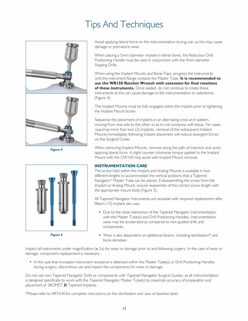
When using the Implant Mounts and Bone Taps, progress the instruments until the instrument flange contacts the Master Tube . It is recommended to use the WR150 Ratchet Wrench with extension for final rotations of these instruments. Once seated, do not continue to rotate these instruments as this can cause damage to the instrumentation or osteotomy (Figure 4) .
The Implant Mounts must be fully engaged within the implant prior to tightening the Implant Mount Screw .
Sequence the placement of implants in an alternating cross arch pattern, moving from one side to the other so as to not compress soft-tissue . For cases requiring more than two (2) implants, removal of the subsequent Implant Mounts immediately following implant placement will reduce divergent forces on the Surgical Guide .
When removing Implant Mounts, remove along the path of insertion and avoid applying lateral force . A slight counter-clockwise torque applied to the Implant Mount with the CW100 may assist with Implant Mount removal .
INSTRUMENTATION CARE The screw held within the Implant and Analog Mounts is available in two different lengths to accommodate the vertical positions that a Tapered Navigator® Master Tube can be placed . If disassembling the screw from the Implant or Analog Mount, ensure reassembly of the correct screw length with the appropriate mount body (Figure 5) .
All Tapered Navigator Instruments are reusable with required replacement after fifteen (15) implant site uses .
• Due to the close interaction of the Tapered Navigator Instrumentation with the Master Tube(s) and Drill Positioning Handles, instrumentation wear may be accelerated as compared to non-guided drills and components .
• Wear is also dependent on additional factors, including sterilization* and bone densities .
Inspect all instruments under magnif ication (≥ 3x) for wear or damage prior to and following surgery . In the case of wear or damage, component replacement is necessary .
• In the case that increased instrument resistance is detected within the Master Tube(s) or Drill Positioning Handles during surgery, discontinue use and inspect the components for wear or damage .
Do not use non-Tapered Navigator Drills or components with Tapered Navigator Surgical Guides, as all instrumentation is designed specifically to work with the Tapered Navigator Master Tube(s) to maximize accuracy of preparation and placement of BIOMET 3i Tapered Implants .
*Please refer to ART630 for complete instructions on the sterilization and care of stainless steel .
Figure 4
Figure 5
14
A key benefit of using the BIOMET 3i Tapered Navigator® System For Guided Surgery is the option to use the Surgical Guide to create a preoperative master cast and a fixed provisional restoration in the laboratory prior to the day of surgery . This may allow the clinician to insert a provisional restoration immediately following implant placement using the Surgical Guide to provide the patient with aesthetic and functional teeth the same day .
Pages 15-30 in this manual are designed to guide surgeons, restorative clinicians and laboratory technicians through the process of fabricating a preoperative master cast and a provisional restoration for insertion following the placement of BIOMET 3i Implants using the Tapered Navigator System For Guided Surgery . The CT software company may also offer the option of fabricating a stereolithographic model for use in creating a master cast .
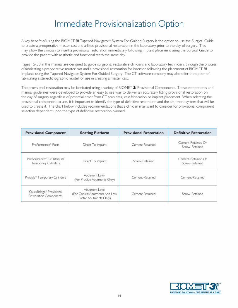
The provisional restoration may be fabricated using a variety of BIOMET 3i Provisional Components . These components and manual guidelines were developed to provide an easy to use way to deliver an accurately fitting provisional restoration on the day of surgery regardless of potential error from CT scan data, cast fabrication or implant placement . When selecting the provisional component to use, it is important to identify the type of definitive restoration and the abutment system that will be used to create it . The chart below includes recommendations that a clinician may want to consider for provisional component selection dependent upon the type of definitive restoration planned .
Immediate Provisionalization Option
Provisional Component Seating Platform Provisional Restoration Definitive Restoration
PreFormance® Posts Direct To Implant Cement-RetainedCement-Retained Or
Screw-Retained
PreFormance® Or Titanium Temporary Cylinders
Direct To Implant Screw-RetainedCement-Retained Or
Screw-Retained
Provide® Temporary CylindersAbutment Level
(For Provide Abutments Only)Cement-Retained Cement-Retained
QuickBridge® Provisional Restoration Components
Abutment Level (For Conical Abutments And Low
Profile Abutments Only)Cement-Retained Screw-Retained
15
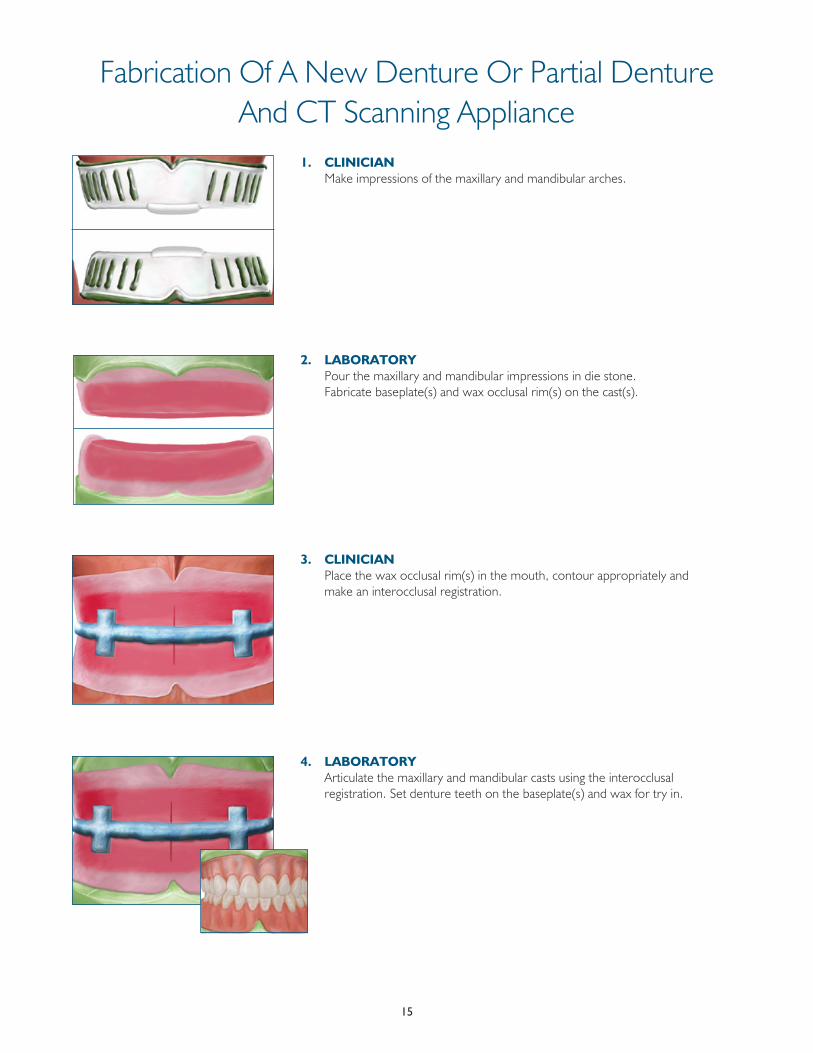
Fabrication Of A New Denture Or Partial Denture And CT Scanning Appliance
1. CLINICIAN Make impressions of the maxillary and mandibular arches .
2. LABORATORY Pour the maxillary and mandibular impressions in die stone .
Fabricate baseplate(s) and wax occlusal rim(s) on the cast(s) .
3. CLINICIAN Place the wax occlusal rim(s) in the mouth, contour appropriately and
make an interocclusal registration .
4. LABORATORY Articulate the maxillary and mandibular casts using the interocclusal
registration . Set denture teeth on the baseplate(s) and wax for try in .
16
Fabrication Of A New Denture Or Partial Denture And CT Scanning Appliance
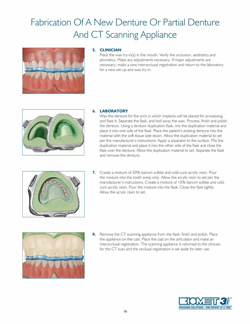
5. CLINICIAN Place the wax try-in(s) in the mouth . Verify the occlusion, aesthetics and
phonetics . Make any adjustments necessary . If major adjustments are necessary, make a new interocclusal registration and return to the laboratory for a new set-up and wax try-in .
6. LABORATORY Wax the denture for the arch in which implants will be placed for processing,
and flask it . Separate the flask, and boil away the wax . Process, finish and polish the denture . Using a denture duplication flask, mix the duplication material and place it into one side of the flask . Place the patient’s existing denture into the material with the soft-tissue side down . Allow the duplication material to set per the manufacturer’s instructions . Apply a separator to the surface . Mix the duplication material and place it into the other side of the flask and close the flask over the denture . Allow the duplication material to set . Separate the flask and remove the denture .
7. Create a mixture of 30% barium sulfate and cold-cure acrylic resin . Pour the mixture into the tooth areas only . Allow the acrylic resin to set per the manufacturer’s instructions . Create a mixture of 10% barium sulfate and cold-cure acrylic resin . Pour the mixture into the flask . Close the flask tightly . Allow the acrylic resin to set .
8. Remove the CT scanning appliance from the flask, finish and polish . Place the appliance on the cast . Place the cast on the articulator and make an interocclusal registration . The scanning appliance is returned to the clinician for the CT scan and the occlusal registration is set aside for later use .
17
Fabrication Of A CT Scanning Appliance Using An Existing Denture
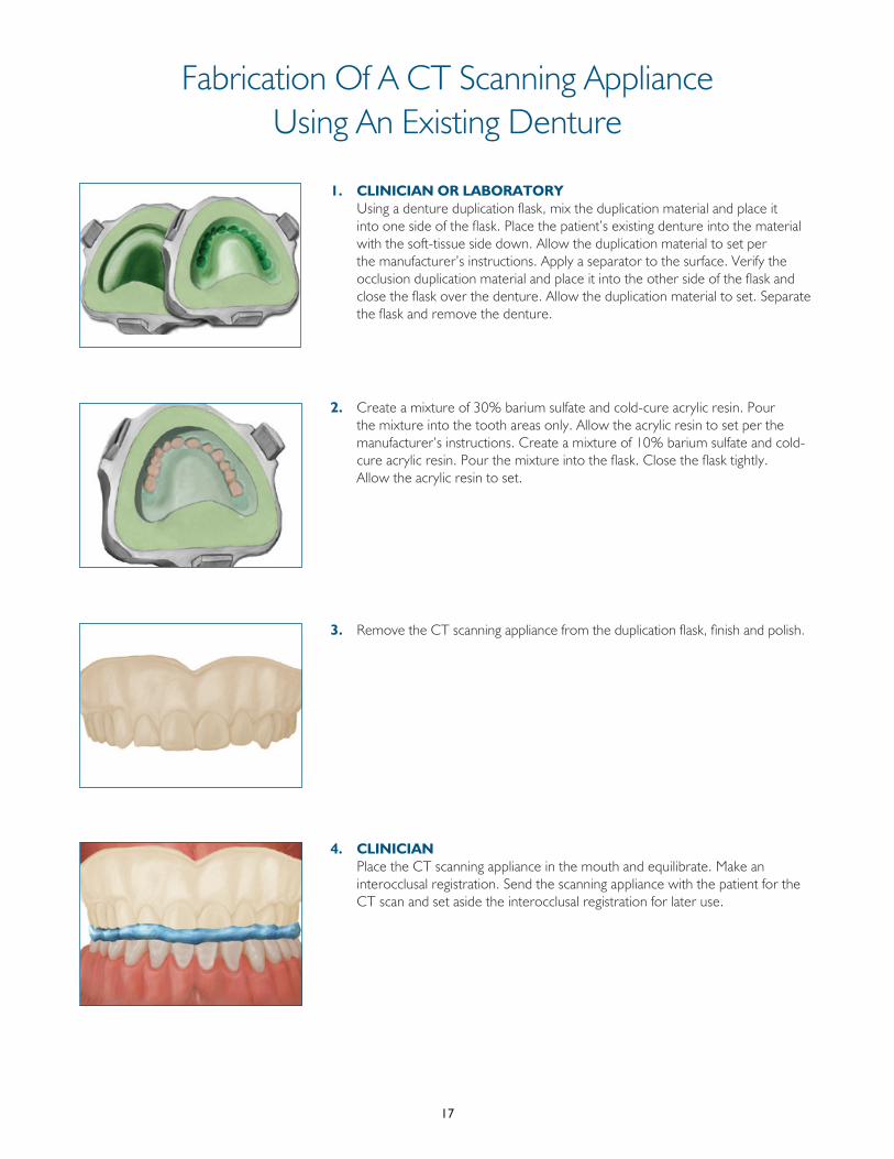
1. CLINICIAN OR LABORATORY Using a denture duplication flask, mix the duplication material and place it
into one side of the flask . Place the patient’s existing denture into the material with the soft-tissue side down . Allow the duplication material to set per the manufacturer’s instructions . Apply a separator to the surface . Verify the occlusion duplication material and place it into the other side of the flask and close the flask over the denture . Allow the duplication material to set . Separate the flask and remove the denture .
2. Create a mixture of 30% barium sulfate and cold-cure acrylic resin . Pour the mixture into the tooth areas only . Allow the acrylic resin to set per the manufacturer’s instructions . Create a mixture of 10% barium sulfate and cold-cure acrylic resin . Pour the mixture into the flask . Close the flask tightly . Allow the acrylic resin to set .
3. Remove the CT scanning appliance from the duplication flask, finish and polish .
4. CLINICIAN Place the CT scanning appliance in the mouth and equilibrate . Make an
interocclusal registration . Send the scanning appliance with the patient for the CT scan and set aside the interocclusal registration for later use .
18
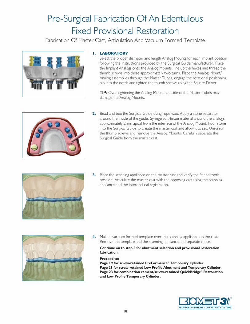
1. LABORATORY Select the proper diameter and length Analog Mounts for each implant position
following the instructions provided by the Surgical Guide manufacturer . Place the Implant Analogs onto the Analog Mounts, line up the hexes and thread the thumb screws into these approximately two turns . Place the Analog Mount/Analog assemblies through the Master Tubes, engage the rotational positioning pin into the notch and tighten the thumb screws using the Square Driver .
TIP: Over-tightening the Analog Mounts outside of the Master Tubes may damage the Analog Mounts .
2. Bead and box the Surgical Guide using rope wax . Apply a stone separator around the inside of the guide . Syringe soft-tissue material around the analogs approximately 2mm apical from the interface of the Analog Mount . Pour stone into the Surgical Guide to create the master cast and allow it to set . Unscrew the thumb screws and remove the Analog Mounts . Carefully separate the Surgical Guide from the master cast .
3. Place the scanning appliance on the master cast and verify the fit and tooth position . Articulate the master cast with the opposing cast using the scanning appliance and the interocclusal registration .
4. Make a vacuum formed template over the scanning appliance on the cast . Remove the template and the scanning appliance and separate those .
Continue on to step 5 for abutment selection and provisional restoration fabrication.
Proceed to: Page 19 for screw-retained PreFormance® Temporary Cylinder. Page 21 for screw-retained Low Profile Abutment and Temporary Cylinder. Page 23 for combination cement/screw-retained QuickBridge® Restoration
and Low Profile Temporary Cylinder.
Pre-Surgical Fabrication Of An EdentulousFixed Provisional Restoration
Fabrication Of Master Cast, Articulation And Vacuum Formed Template
19
Continued from Laboratory Procedure (Steps 1-4) on page 18 .
Abutment Selection5. PreFormance Temporary Cylinders are designed to allow acrylic resin to be
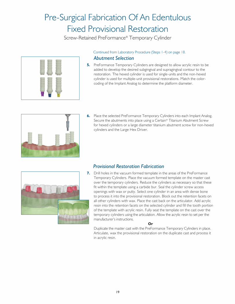
added to develop the desired subgingival and supragingival contour to the restoration . The hexed cylinder is used for single-units and the non-hexed cylinder is used for multiple-unit provisional restorations . Match the color-coding of the Implant Analog to determine the platform diameter .
6. Place the selected PreFormance Temporary Cylinders into each Implant Analog . Secure the abutments into place using a Certain® Titanium Abutment Screw for hexed cylinders or a large diameter titanium abutment screw for non-hexed cylinders and the Large Hex Driver .
Provisional Restoration Fabrication7. Drill holes in the vacuum formed template in the areas of the PreFormance
Temporary Cylinders . Place the vacuum formed template on the master cast over the temporary cylinders . Reduce the cylinders as necessary so that these fit within the template using a carbide bur . Seal the cylinder screw access openings with wax or putty . Select one cylinder in an area with dense bone to process it into the provisional restoration . Block out the retention facets on all other cylinders with wax . Place the cast back on the articulator . Add acrylic resin into the retention facets on the selected cylinder and fill the tooth portion of the template with acrylic resin . Fully seat the template on the cast over the temporary cylinders using the articulation . Allow the acrylic resin to set per the manufacturer’s instructions .
Or Duplicate the master cast with the PreFormance Temporary Cylinders in place .
Articulate, wax the provisional restoration on the duplicate cast and process it in acrylic resin .
Pre-Surgical Fabrication Of An EdentulousFixed Provisional Restoration
Screw-Retained PreFormance® Temporary Cylinder

20
8. Clear the cylinder screw access opening and remove the abutment screw from the selected cylinder . Remove the template from the cast over the non-processed cylinders with the selected temporary cylinder inside the acrylic resin . Remove the provisional restoration from the template . Remove all excess acrylic resin from around the margin areas of the provisional restoration . Relieve the holes for the other cylinders as necessary so that the provisional restoration can be placed over those and removed easily . Fill in any voids . Finish the restoration to the desired contour and polish .
CT Guided Surgical Implant Placement9. CLINICIAN Place the implants using the Surgical Guide and following the Surgical Guide
provided by the guide manufacturer .
See page 11 for an example of a Surgical Plan .
Post Surgical Delivery Of Provisional Restoration10. Place a PreFormance Temporary Cylinder on the implant that is on the
opposite of the arch from the selected lab-processed cylinder . Secure the cylinder into place using an abutment screw and the Large Hex Driver . Seal the screw access opening with impression material . Try in the provisional restoration over the PreFormance Temporary Cylinder and secure it into place by threading an abutment screw through the lab-processed cylinder . Verify that it fits to the cylinder margins properly . Adjust the occlusion as indicated and remove the provisional restoration .
11. Place acrylic resin into the retention facets on the PreFormance Temporary Cylinder and into the cylinder area on the provisional restoration . Seat the provisional restoration over the cylinder and secure it into place by threading an abutment screw through the lab-processed cylinder . Have the patient close into centric occlusion . Allow the acrylic resin to set per the manufacturer’s instructions . Remove the abutment screws and remove the provisional restoration . Place the remaining cylinders on the implants and lute these into the provisional restoration by repeating the prior steps . Fill in any voids . Remove any excess acrylic resin and polish . Secure the provisional restoration into place with the titanium abutment screws using the Large Hex Driver . Torque the screws to 10Ncm using the Large Hex Driver Tip and a torque device . Place a temporary filling material into the screw access openings and seal those with composite resin . Adjust the occlusion as indicated . If a flap procedure was used during surgery, suture the soft-tissue around the provisional restoration .
Pre-Surgical Fabrication Of An EdentulousFixed Provisional Restoration
Screw-Retained PreFormance® Temporary Cylinder
21
Continued from Laboratory Procedure (Steps 1-4) on page 18 .
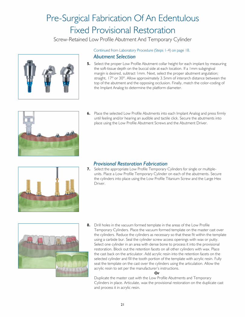
Abutment Selection5. Select the proper Low Profile Abutment collar height for each implant by measuring
the soft-tissue depth on the buccal side at each location . If a 1mm subgingival margin is desired, subtract 1mm . Next, select the proper abutment angulation; straight, 17º or 30º . Allow approximately 3 .5mm of interarch distance between the top of the abutment and the opposing occlusion . Finally, match the color-coding of the Implant Analog to determine the platform diameter .
6. Place the selected Low Profile Abutments into each Implant Analog and press firmly until feeling and/or hearing an audible and tactile click . Secure the abutments into place using the Low Profile Abutment Screws and the Abutment Driver .
Provisional Restoration Fabrication7. Select the appropriate Low Profile Temporary Cylinders for single or multiple-
units . Place a Low Profile Temporary Cylinder on each of the abutments . Secure the cylinders into place using the Low Profile Titanium Screw and the Large Hex Driver .
8. Drill holes in the vacuum formed template in the areas of the Low Profile Temporary Cylinders . Place the vacuum formed template on the master cast over the cylinders . Reduce the cylinders as necessary so that these fit within the template using a carbide bur . Seal the cylinder screw access openings with wax or putty . Select one cylinder in an area with dense bone to process it into the provisional restoration . Block out the retention facets on all other cylinders with wax . Place the cast back on the articulator . Add acrylic resin into the retention facets on the selected cylinder and fill the tooth portion of the template with acrylic resin . Fully seat the template on the cast over the cylinders using the articulation . Allow the acrylic resin to set per the manufacturer’s instructions .
Or Duplicate the master cast with the Low Profile Abutments and Temporary
Cylinders in place . Articulate, wax the provisional restoration on the duplicate cast and process it in acrylic resin .
Pre-Surgical Fabrication Of An EdentulousFixed Provisional Restoration
Screw-Retained Low Profile Abutment And Temporary Cylinder
22
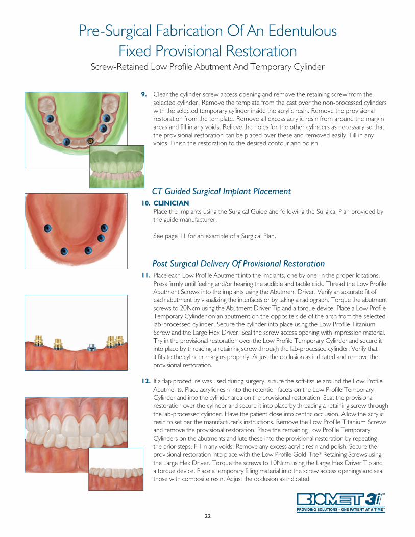
9. Clear the cylinder screw access opening and remove the retaining screw from the selected cylinder . Remove the template from the cast over the non-processed cylinders with the selected temporary cylinder inside the acrylic resin . Remove the provisional restoration from the template . Remove all excess acrylic resin from around the margin areas and fill in any voids . Relieve the holes for the other cylinders as necessary so that the provisional restoration can be placed over these and removed easily . Fill in any voids . Finish the restoration to the desired contour and polish .
CT Guided Surgical Implant Placement10. CLINICIAN Place the implants using the Surgical Guide and following the Surgical Plan provided by
the guide manufacturer .
See page 11 for an example of a Surgical Plan .
Post Surgical Delivery Of Provisional Restoration11. Place each Low Profile Abutment into the implants, one by one, in the proper locations .
Press firmly until feeling and/or hearing the audible and tactile click . Thread the Low Profile Abutment Screws into the implants using the Abutment Driver . Verify an accurate fit of each abutment by visualizing the interfaces or by taking a radiograph . Torque the abutment screws to 20Ncm using the Abutment Driver Tip and a torque device . Place a Low Profile Temporary Cylinder on an abutment on the opposite side of the arch from the selected lab-processed cylinder . Secure the cylinder into place using the Low Profile Titanium Screw and the Large Hex Driver . Seal the screw access opening with impression material . Try in the provisional restoration over the Low Profile Temporary Cylinder and secure it into place by threading a retaining screw through the lab-processed cylinder . Verify that it fits to the cylinder margins properly . Adjust the occlusion as indicated and remove the provisional restoration .
12. If a flap procedure was used during surgery, suture the soft-tissue around the Low Profile Abutments . Place acrylic resin into the retention facets on the Low Profile Temporary Cylinder and into the cylinder area on the provisional restoration . Seat the provisional restoration over the cylinder and secure it into place by threading a retaining screw through the lab-processed cylinder . Have the patient close into centric occlusion . Allow the acrylic resin to set per the manufacturer’s instructions . Remove the Low Profile Titanium Screws and remove the provisional restoration . Place the remaining Low Profile Temporary Cylinders on the abutments and lute these into the provisional restoration by repeating the prior steps . Fill in any voids . Remove any excess acrylic resin and polish . Secure the provisional restoration into place with the Low Profile Gold-Tite® Retaining Screws using the Large Hex Driver . Torque the screws to 10Ncm using the Large Hex Driver Tip and a torque device . Place a temporary filling material into the screw access openings and seal those with composite resin . Adjust the occlusion as indicated .
Pre-Surgical Fabrication Of An EdentulousFixed Provisional Restoration
Screw-Retained Low Profile Abutment And Temporary Cylinder
23
Continued from Laboratory Procedure (Steps 1-4) on page 18 .
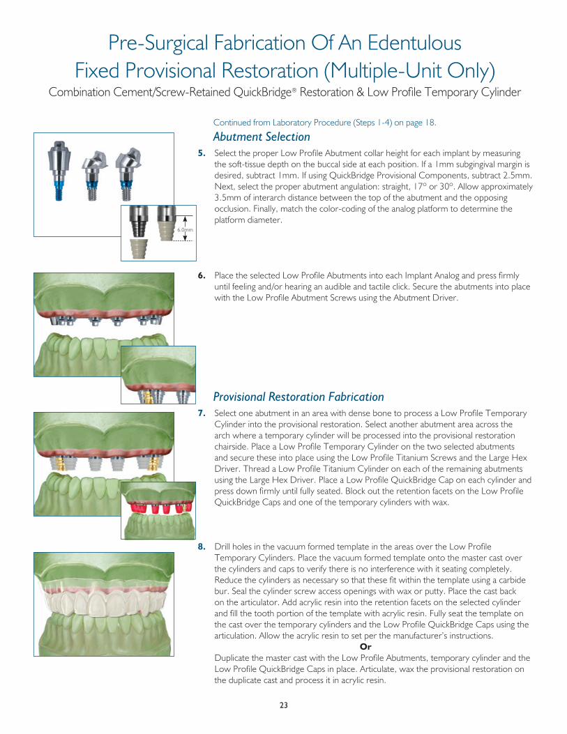
Abutment Selection5. Select the proper Low Profile Abutment collar height for each implant by measuring
the soft-tissue depth on the buccal side at each position . If a 1mm subgingival margin is desired, subtract 1mm . If using QuickBridge Provisional Components, subtract 2 .5mm . Next, select the proper abutment angulation: straight, 17º or 30º . Allow approximately 3 .5mm of interarch distance between the top of the abutment and the opposing occlusion . Finally, match the color-coding of the analog platform to determine the platform diameter .
6. Place the selected Low Profile Abutments into each Implant Analog and press firmly until feeling and/or hearing an audible and tactile click . Secure the abutments into place with the Low Profile Abutment Screws using the Abutment Driver .
Provisional Restoration Fabrication7. Select one abutment in an area with dense bone to process a Low Profile Temporary
Cylinder into the provisional restoration . Select another abutment area across the arch where a temporary cylinder will be processed into the provisional restoration chairside . Place a Low Profile Temporary Cylinder on the two selected abutments and secure these into place using the Low Profile Titanium Screws and the Large Hex Driver . Thread a Low Profile Titanium Cylinder on each of the remaining abutments using the Large Hex Driver . Place a Low Profile QuickBridge Cap on each cylinder and press down firmly until fully seated . Block out the retention facets on the Low Profile QuickBridge Caps and one of the temporary cylinders with wax .
8. Drill holes in the vacuum formed template in the areas over the Low Profile Temporary Cylinders . Place the vacuum formed template onto the master cast over the cylinders and caps to verify there is no interference with it seating completely . Reduce the cylinders as necessary so that these fit within the template using a carbide bur . Seal the cylinder screw access openings with wax or putty . Place the cast back on the articulator . Add acrylic resin into the retention facets on the selected cylinder and fill the tooth portion of the template with acrylic resin . Fully seat the template on the cast over the temporary cylinders and the Low Profile QuickBridge Caps using the articulation . Allow the acrylic resin to set per the manufacturer’s instructions .
Or Duplicate the master cast with the Low Profile Abutments, temporary cylinder and the
Low Profile QuickBridge Caps in place . Articulate, wax the provisional restoration on the duplicate cast and process it in acrylic resin .
6 .0mm
Pre-Surgical Fabrication Of An EdentulousFixed Provisional Restoration (Multiple-Unit Only)
Combination Cement/Screw-Retained QuickBridge® Restoration & Low Profile Temporary Cylinder
24
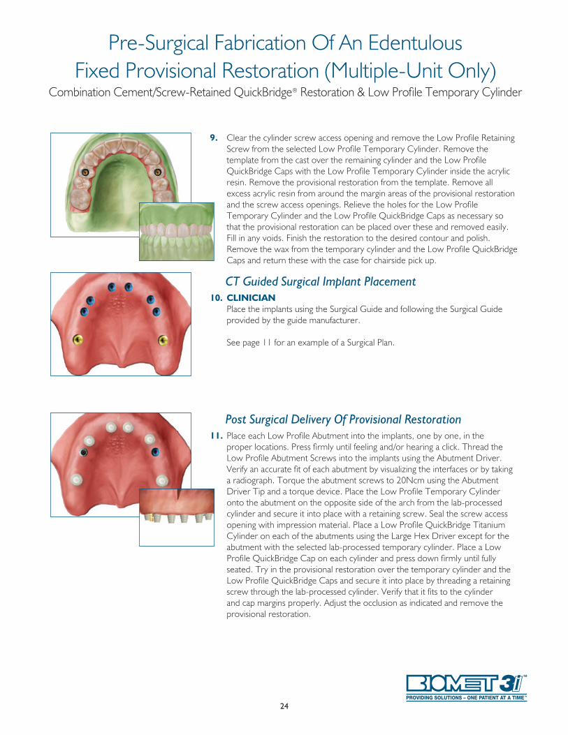
9. Clear the cylinder screw access opening and remove the Low Profile Retaining Screw from the selected Low Profile Temporary Cylinder . Remove the template from the cast over the remaining cylinder and the Low Profile QuickBridge Caps with the Low Profile Temporary Cylinder inside the acrylic resin . Remove the provisional restoration from the template . Remove all excess acrylic resin from around the margin areas of the provisional restoration and the screw access openings . Relieve the holes for the Low Profile Temporary Cylinder and the Low Profile QuickBridge Caps as necessary so that the provisional restoration can be placed over these and removed easily . Fill in any voids . Finish the restoration to the desired contour and polish . Remove the wax from the temporary cylinder and the Low Profile QuickBridge Caps and return these with the case for chairside pick up .
CT Guided Surgical Implant Placement10. CLINICIAN Place the implants using the Surgical Guide and following the Surgical Guide
provided by the guide manufacturer .
See page 11 for an example of a Surgical Plan .
Post Surgical Delivery Of Provisional Restoration11. Place each Low Profile Abutment into the implants, one by one, in the
proper locations . Press firmly until feeling and/or hearing a click . Thread the Low Profile Abutment Screws into the implants using the Abutment Driver . Verify an accurate fit of each abutment by visualizing the interfaces or by taking a radiograph . Torque the abutment screws to 20Ncm using the Abutment Driver Tip and a torque device . Place the Low Profile Temporary Cylinder onto the abutment on the opposite side of the arch from the lab-processed cylinder and secure it into place with a retaining screw . Seal the screw access opening with impression material . Place a Low Profile QuickBridge Titanium Cylinder on each of the abutments using the Large Hex Driver except for the abutment with the selected lab-processed temporary cylinder . Place a Low Profile QuickBridge Cap on each cylinder and press down firmly until fully seated . Try in the provisional restoration over the temporary cylinder and the Low Profile QuickBridge Caps and secure it into place by threading a retaining screw through the lab-processed cylinder . Verify that it fits to the cylinder and cap margins properly . Adjust the occlusion as indicated and remove the provisional restoration .
Pre-Surgical Fabrication Of An EdentulousFixed Provisional Restoration (Multiple-Unit Only)
Combination Cement/Screw-Retained QuickBridge® Restoration & Low Profile Temporary Cylinder
25
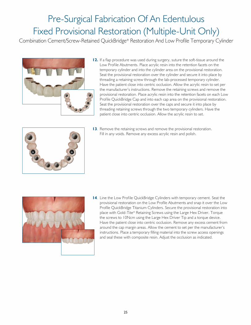
12. If a flap procedure was used during surgery, suture the soft-tissue around the Low Prof ile Abutments . Place acrylic resin into the retention facets on the temporary cylinder and into the cylinder area on the provisional restoration . Seat the provisional restoration over the cylinder and secure it into place by threading a retaining screw through the lab-processed temporary cylinder . Have the patient close into centric occlusion . Allow the acrylic resin to set per the manufacturer’s instructions . Remove the retaining screws and remove the provisional restoration . Place acrylic resin into the retention facets on each Low Prof ile QuickBridge Cap and into each cap area on the provisional restoration . Seat the provisional restoration over the caps and secure it into place by threading retaining screws through the two temporary cylinders . Have the patient close into centric occlusion . Allow the acrylic resin to set .
13 . Remove the retaining screws and remove the provisional restoration . Fill in any voids . Remove any excess acrylic resin and polish .
14 . Line the Low Prof ile QuickBridge Cylinders with temporary cement . Seat the provisional restoration on the Low Profile Abutments and snap it over the Low Profile QuickBridge Titanium Cylinders . Secure the provisional restoration into place with Gold-Tite® Retaining Screws using the Large Hex Driver . Torque the screws to 10Ncm using the Large Hex Driver Tip and a torque device . Have the patient close into centric occlusion . Remove any excess cement from around the cap margin areas . Allow the cement to set per the manufacturer’s instructions . Place a temporary filling material into the screw access openings and seal these with composite resin . Adjust the occlusion as indicated .
Pre-Surgical Fabrication Of An EdentulousFixed Provisional Restoration (Multiple-Unit Only)
Combination Cement/Screw-Retained QuickBridge® Restoration And Low Profile Temporary Cylinder
26
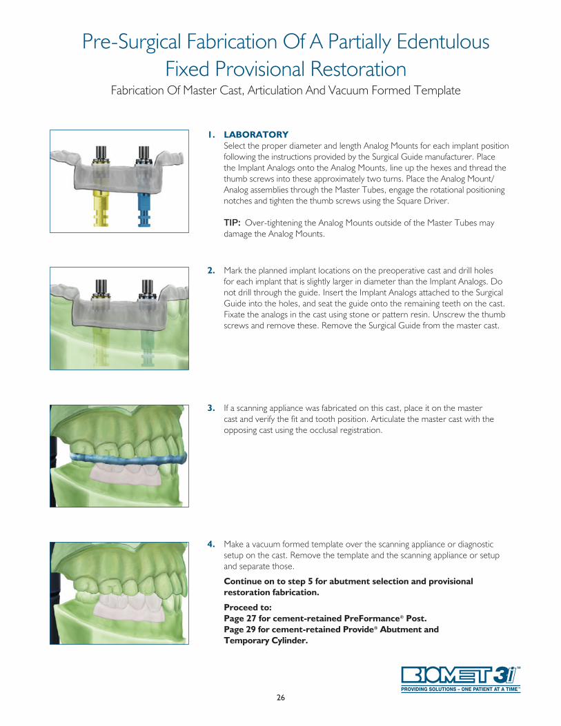
1. LABORATORY Select the proper diameter and length Analog Mounts for each implant position
following the instructions provided by the Surgical Guide manufacturer . Place the Implant Analogs onto the Analog Mounts, line up the hexes and thread the thumb screws into these approximately two turns . Place the Analog Mount/Analog assemblies through the Master Tubes, engage the rotational positioning notches and tighten the thumb screws using the Square Driver .
TIP: Over-tightening the Analog Mounts outside of the Master Tubes may damage the Analog Mounts .
2. Mark the planned implant locations on the preoperative cast and drill holes for each implant that is slightly larger in diameter than the Implant Analogs . Do not drill through the guide . Insert the Implant Analogs attached to the Surgical Guide into the holes, and seat the guide onto the remaining teeth on the cast . Fixate the analogs in the cast using stone or pattern resin . Unscrew the thumb screws and remove these . Remove the Surgical Guide from the master cast .
3. If a scanning appliance was fabricated on this cast, place it on the master cast and verify the fit and tooth position . Articulate the master cast with the opposing cast using the occlusal registration .
4. Make a vacuum formed template over the scanning appliance or diagnostic setup on the cast . Remove the template and the scanning appliance or setup and separate those .
Continue on to step 5 for abutment selection and provisional restoration fabrication.
Proceed to: Page 27 for cement-retained PreFormance® Post. Page 29 for cement-retained Provide® Abutment and
Temporary Cylinder.
Pre-Surgical Fabrication Of A Partially EdentulousFixed Provisional Restoration
Fabrication Of Master Cast, Articulation And Vacuum Formed Template
27
Continued from Laboratory Procedure (Steps 1-4) on page 26 .
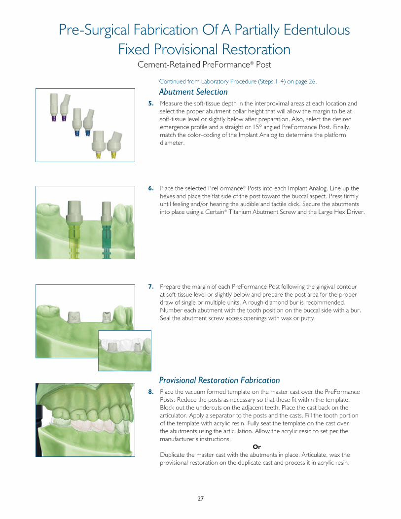
Abutment Selection5. Measure the soft-tissue depth in the interproximal areas at each location and
select the proper abutment collar height that will allow the margin to be at soft-tissue level or slightly below after preparation . Also, select the desired emergence profile and a straight or 15º angled PreFormance Post . Finally, match the color-coding of the Implant Analog to determine the platform diameter .
6. Place the selected PreFormance® Posts into each Implant Analog . Line up the hexes and place the flat side of the post toward the buccal aspect . Press firmly until feeling and/or hearing the audible and tactile click . Secure the abutments into place using a Certain® Titanium Abutment Screw and the Large Hex Driver .
7. Prepare the margin of each PreFormance Post following the gingival contour at soft-tissue level or slightly below and prepare the post area for the proper draw of single or multiple units . A rough diamond bur is recommended . Number each abutment with the tooth position on the buccal side with a bur . Seal the abutment screw access openings with wax or putty .
Provisional Restoration Fabrication8. Place the vacuum formed template on the master cast over the PreFormance
Posts . Reduce the posts as necessary so that these fit within the template . Block out the undercuts on the adjacent teeth . Place the cast back on the articulator . Apply a separator to the posts and the casts . Fill the tooth portion of the template with acrylic resin . Fully seat the template on the cast over the abutments using the articulation . Allow the acrylic resin to set per the manufacturer’s instructions .
Or Duplicate the master cast with the abutments in place . Articulate, wax the
provisional restoration on the duplicate cast and process it in acrylic resin .
Pre-Surgical Fabrication Of A Partially EdentulousFixed Provisional Restoration
Cement-Retained PreFormance® Post
28
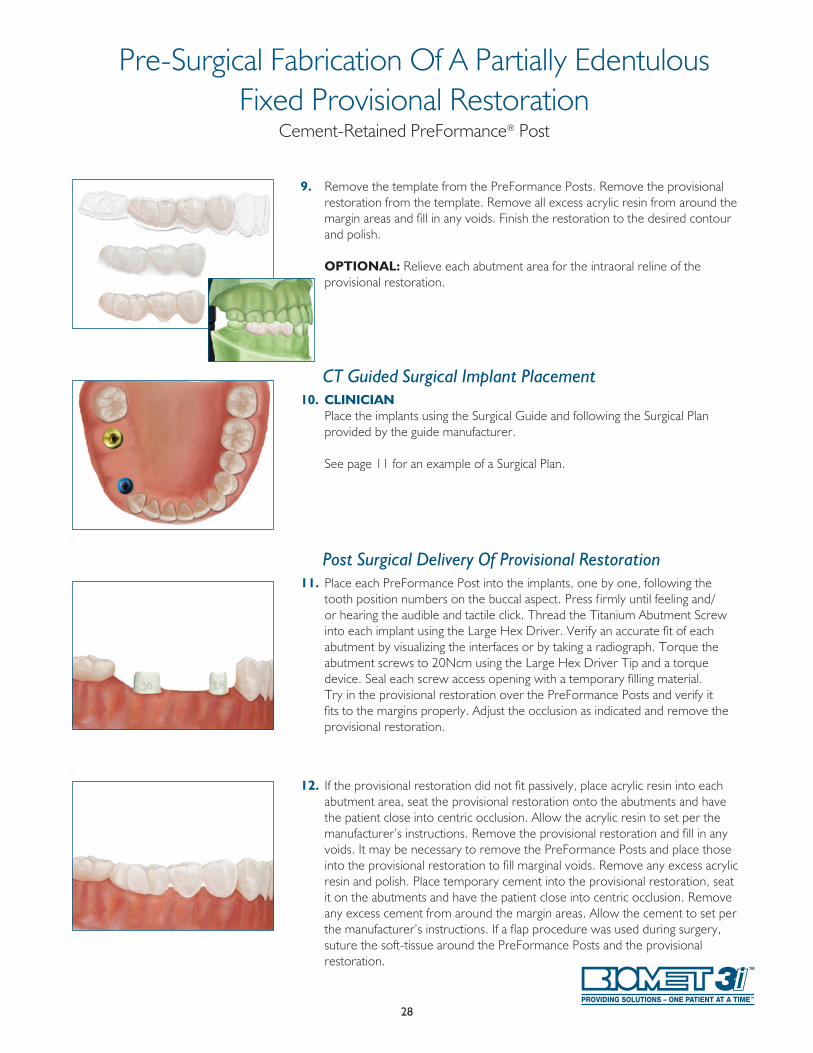
9. Remove the template from the PreFormance Posts . Remove the provisional restoration from the template . Remove all excess acrylic resin from around the margin areas and fill in any voids . Finish the restoration to the desired contour and polish .
OPTIONAL: Relieve each abutment area for the intraoral reline of the provisional restoration .
CT Guided Surgical Implant Placement10. CLINICIAN Place the implants using the Surgical Guide and following the Surgical Plan
provided by the guide manufacturer . See page 11 for an example of a Surgical Plan .
Post Surgical Delivery Of Provisional Restoration11. Place each PreFormance Post into the implants, one by one, following the
tooth position numbers on the buccal aspect . Press f irmly until feeling and/or hearing the audible and tactile click . Thread the Titanium Abutment Screw into each implant using the Large Hex Driver . Verify an accurate fit of each abutment by visualizing the interfaces or by taking a radiograph . Torque the abutment screws to 20Ncm using the Large Hex Driver Tip and a torque device . Seal each screw access opening with a temporary filling material . Try in the provisional restoration over the PreFormance Posts and verify it fits to the margins properly . Adjust the occlusion as indicated and remove the provisional restoration .
12. If the provisional restoration did not fit passively, place acrylic resin into each abutment area, seat the provisional restoration onto the abutments and have the patient close into centric occlusion . Allow the acrylic resin to set per the manufacturer’s instructions . Remove the provisional restoration and fill in any voids . It may be necessary to remove the PreFormance Posts and place those into the provisional restoration to fill marginal voids . Remove any excess acrylic resin and polish . Place temporary cement into the provisional restoration, seat it on the abutments and have the patient close into centric occlusion . Remove any excess cement from around the margin areas . Allow the cement to set per the manufacturer’s instructions . If a flap procedure was used during surgery, suture the soft-tissue around the PreFormance Posts and the provisional restoration .
Pre-Surgical Fabrication Of A Partially EdentulousFixed Provisional Restoration
Cement-Retained PreFormance® Post
29
Continued from Laboratory Procedure (Steps 1-4) on page 26 .
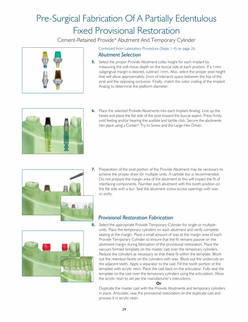
Abutment Selection5. Select the proper Provide Abutment collar height for each implant by
measuring the soft-tissue depth on the buccal side at each position . If a 1mm subgingival margin is desired, subtract 1mm . Also, select the proper post height that will allow approximately 2mm of interarch space between the top of the post and the opposing occlusion . Finally, match the color-coding of the Implant Analog to determine the platform diameter .
6. Place the selected Proivde Abutments into each Implant Analog . Line up the hexes and place the flat side of the post toward the buccal aspect . Press firmly until feeling and/or hearing the audible and tactile click . Secure the abutments into place using a Certain® Try-In Screw and the Large Hex Driver .
7. Preparation of the post portion of the Provide Abutment may be necessary to achieve the proper draw for multiple-units . A carbide bur is recommended . Do not prepare the margin area of the abutment as this will impact the fit of interfacing components . Number each abutment with the tooth position on the flat side with a bur . Seal the abutment screw access openings with wax or putty .
Provisional Restoration Fabrication8. Select the appropriate Provide Temporary Cylinder for single or multiple-
units . Place the temporary cylinders on each abutment and verify complete seating at the margin . Place a small amount of wax at the margin area of each Provide Temporary Cylinder to ensure that the fit remains passive on the abutment margin during fabrication of the provisional restoration . Place the vacuum formed template on the master cast over the temporary cylinders . Reduce the cylinders as necessary so that these fit within the template . Block out the retention facets on the cylinders with wax . Block out the undercuts on the adjacent teeth . Apply a separator to the cast . Fill the tooth portion of the template with acrylic resin . Place the cast back on the articulator . Fully seat the template on the cast over the temporary cylinders using the articulation . Allow the acrylic resin to set per the manufacturer’s instructions .
Or Duplicate the master cast with the Proivde Abutments and temporary cylinders
in place . Articulate, wax the provisional restoration on the duplicate cast and process it in acrylic resin .
Pre-Surgical Fabrication Of A Partially EdentulousFixed Provisional Restoration
Cement-Retained Provide® Abutment And Temporary Cylinder
30
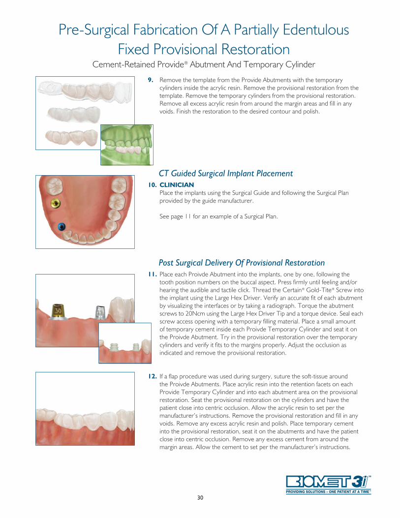
9. Remove the template from the Provide Abutments with the temporary cylinders inside the acrylic resin . Remove the provisional restoration from the template . Remove the temporary cylinders from the provisional restoration . Remove all excess acrylic resin from around the margin areas and fill in any voids . Finish the restoration to the desired contour and polish .
CT Guided Surgical Implant Placement10. CLINICIAN Place the implants using the Surgical Guide and following the Surgical Plan
provided by the guide manufacturer .
See page 11 for an example of a Surgical Plan .
Post Surgical Delivery Of Provisional Restoration11. Place each Proivde Abutment into the implants, one by one, following the
tooth position numbers on the buccal aspect . Press firmly until feeling and/or hearing the audible and tactile click . Thread the Certain® Gold-Tite® Screw into the implant using the Large Hex Driver . Verify an accurate fit of each abutment by visualizing the interfaces or by taking a radiograph . Torque the abutment screws to 20Ncm using the Large Hex Driver Tip and a torque device . Seal each screw access opening with a temporary filling material . Place a small amount of temporary cement inside each Proivde Temporary Cylinder and seat it on the Proivde Abutment . Try in the provisional restoration over the temporary cylinders and verify it fits to the margins properly . Adjust the occlusion as indicated and remove the provisional restoration .
12. If a flap procedure was used during surgery, suture the soft-tissue around the Proivde Abutments . Place acrylic resin into the retention facets on each Provide Temporary Cylinder and into each abutment area on the provisional restoration . Seat the provisional restoration on the cylinders and have the patient close into centric occlusion . Allow the acrylic resin to set per the manufacturer’s instructions . Remove the provisional restoration and fill in any voids . Remove any excess acrylic resin and polish . Place temporary cement into the provisional restoration, seat it on the abutments and have the patient close into centric occlusion . Remove any excess cement from around the margin areas . Allow the cement to set per the manufacturer’s instructions .
Pre-Surgical Fabrication Of A Partially EdentulousFixed Provisional Restoration
Cement-Retained Provide® Abutment And Temporary Cylinder


INST1149 REV A 06/14
JoinUs
FollowUs
WatchUs
DownloadIt
Certain, Gold-Tite, Navigator, PreFormance, PREVAIL, Provide and QuickBridge are registered trademarks of BIOMET 3i LLC. Providing Solutions – One Patient At A Time is a trademark of BIOMET 3i LLC. ©2014 BIOMET 3i LLC.
All trademarks herein are the property of BIOMET 3i LLC unless otherwise indicated. This material is intended for clinicians only and is NOT intended for patient distribution. This material is not to be redistributed, duplicated or disclosed without the express written consent of BIOMET 3i. For additional product information, including indications, contraindications, warnings, precautions and potential adverse effects, please visit the BIOMET 3i Website: www.ifu.biomet3i.com.
Looking For The Latest In Accurate Implant Treatment?Then Navigator® Is For You!
www .biomet3i .com
Not Available In All Markets. For More Information, Please Contact Your Local BIOMET 3i Sales Representative.
Global Headquarters4555 Riverside DrivePalm Beach Gardens, FL 334101-800-342-5454Outside the U.S.: +1-561-776-6700Fax: +1-561-776-1272www.biomet3i.com
BIOMET 3iDental Iberica S.L.WTC Almeda Park, Ed. 1, Planta 1ªPl. de la Pau, s/n08940, Cornellà de Llobregat(Barcelona) SpainPhone: +34-93-470-55-00Fax: +34-93-371-78-49
EC REP