Hydraulic Test Kit AMK 2013
49
HYDRAULIC TEST KIT Submitted in the partial fulfillment of the requirement for the award “DIPLOMA IN MECHANICALENGINEERING ” SUBMITTED BY: 1. S.BARANI 4. E.VIGNESH 2. S.MURALI 5. RAMAMOORTHY ANAND 3. N.S.VENKATESAN 6. Under guidance of Mr. N.MUTHUKUMAR MARCH 2013 DEPARTMENT OF MECHANICAL ENGINEERING.
-
Upload
chockalingam-athilingam -
Category
Documents
-
view
6 -
download
0
description
HYDRAULIC TEST KIT
Transcript of Hydraulic Test Kit AMK 2013

HYDRAULIC TEST KIT
Submitted in the partial fulfillment of the requirement for the award
“DIPLOMA IN MECHANICALENGINEERING ”
SUBMITTED BY:
1. S.BARANI 4. E.VIGNESH 2. S.MURALI 5. RAMAMOORTHY ANAND 3. N.S.VENKATESAN 6.
Under guidance of
Mr. N.MUTHUKUMAR
MARCH 2013
DEPARTMENT OF MECHANICAL ENGINEERING.
AMK TECHNOLOGICAL POLYTECHNIC COLLEGECHENNAI-602103

AMK TECHNOLOGICAL POLYTECHNIC COLLEGECHENNAI-602103
BONAFIDE CERTIFICATE
This is to certify that this Project work on
“HYDRAULC TEST KIT”
submitted by …………………… ……………. Reg. No. ……………
in partial fulfillment for the award of
DIPLOMA IN MECHANICAL ENGINEERING
This is the bonafide record of work carried out by him under our supervision during the
year 2013
Submitted for the Viva-voce exam held on ……………..
H.O.D. PROJECT GUIDE
INTERNAL EXAMINER EXTERNAL EXAMINER

ACKNOWLEDGEMENT
ACKNOWLEDGEMENT

At the outset, we would like to emphasize our sincere thanks to the Principal Mr.
R.J.KUMAR M.E for encouragement and valuable advice.
we thank our Esquired Head of Department Mr R.RAJKUMAR M.E for
presenting his felications on us.
We are grateful on our Entourages Mr. N.MUTHUKUMAR for guiding in
various aspects of the project making it a grand success.
We also owe our sincere thanks to all staff members of the MTMR and
FOUNDRY Department.
Ultimately, we extend our thanks to all who had rendered their co-operation for
the success of the project.
CONTENTS
CONTENTS
1. INTRODUCTION
2. SYNOPSIS

3. PROJECT PLANNING
4. CONSTRUCTION DETAILS
5. WORKING PRINCIPLE
6. SPARE PARTS DRAWING
7. APPLICATION
8. ADVANTAGES AND DISADVANTAGES
9. FEATURES OF THIS PROJECT
10. SAFTY,CARE AND MAINTENANCE
11. PAINTING AND FINISHING
12. COST ESTIMATION
13. CONCLUSION
14. BIBLIOGRAPHY
15. PHOTO VIEW

INTRODUCTION
INTRODUCTION
This is a self – assessment test on the part of the students to assess his competency
in creativity.
During the course of study, the student is put on a sound theoretical foundation of
various mechanical engineering subjects and of course, to a satisfactory extent.

Opportunities are made available to him to work on different kinds of machines, so that
he is exposed to various kinds of manufacturing process.
As a students learn more and more his hold on production technology becomes
stronger. He attains a stage of perfection, when he himself is able to design and
fabricate a device.
This is the project work. That is the testimony for the strenuous training, which
the student had in the institute. This assures that he is no more a student, he is an
engineer.
This report discuses the necessity of the project and various aspects of planning ,
design, selection of materials, fabrication, erection, estimation and testing.

OBJECTIVE
OBJECTIVE;
• To Reduce the Workmen fatigue, Time and Increase in productivity by frequent
loading and unloading of machining centers
• To reduce the downtime and save the labour cost.

ABSTRACT
OIL PUMP TESTER is equipment that is used to test the performance of the oil pump. In
lubrication system of engine the oil pump plays a vital role. Serious damages are caused to the
engine components when the pressure developed by the oil pump is low. Hence testing the oil
pump becomes very important. To check the condition of the pump the actual performance of
the pump is compared with the standard performance that is required for the efficient oil pump
is measured at a constant pressure and at a rated RPM of the efficient oil pump is measured at a
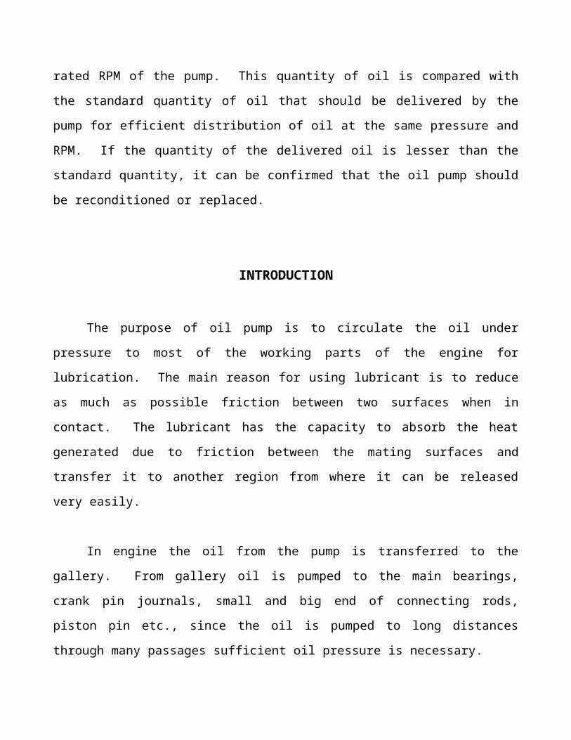
constant pressure and at a rated RPM of the pump. This quantity of oil is compared with the
standard quantity of oil that should be delivered by the pump for efficient distribution of oil at

the same pressure and RPM. If the quantity of the delivered oil is lesser than the standard
quantity, it can be confirmed that the oil pump should be reconditioned or replaced.
INTRODUCTION
The purpose of oil pump is to circulate the oil under pressure to most of the working
parts of the engine for lubrication. The main reason for using lubricant is to reduce as much as
possible friction between two surfaces when in contact. The lubricant has the capacity to
absorb the heat generated due to friction between the mating surfaces and transfer it to another
region from where it can be released very easily.
In engine the oil from the pump is transferred to the gallery. From gallery oil is pumped
to the main bearings, crank pin journals, small and big end of connecting rods, piston pin etc.,
since the oil is pumped to long distances through many passages sufficient oil pressure is
necessary.
The required pressure for most of the engine is 170-240 Kpa. But this may also increase
to 450 Kpa during certain conditions. The delivery oil at the pump shaft RPM of 600 at
3Kg/cm² should be 6 LPM. The pump maintains a fixed oil discharge quantity once the engine
reduce or exceeds a specified speed, thus reduce torque losses when the parts preventing the
pressure build up. So the oil pump must no be used in the engine without testing. Thus to test
any type of oil pump the tester was designed and fabricated by us.

FABRICATION OF HYDRAULIC TEST KIT
Project Elements;
1.hand operated large oil cylinder PUMP.
2. flow control valve.
3.PRESSURE GAUGE
4.M.S.FABRICATED TEST STAND .
5. oil pipe (flexible)
ADVANTAGES;

ADVANTAGES;
1.Oil pressing device is smoother in action more constant in holding
proper and more convenient than other hand operated pressing and
save human energy
2.The use of oil cylinder reduces operator effort
3.Reduces waste motions which cause fatigues to worker.
4. This system is used to test or identify faulty oil pump .

PROJECT PLANNING

PROJECT PLANNING
CONCEPT OF THE PROJECT
Before starting every project its planning is to be done. In planning functions are
life the functions of nerves in our body. planning a project is a very important task and
should be taken up with great care as the efficiency of the whole project largely depends
upon its planning, while planning a project each and every details should be worked out
in anticipation should be carefully considered with all the relative provisions aspects.
PROJECT CAPACITY
The capacity of the project must be decided considering the amount of money
which can be invested. The availability of material and machines and usefulness of the
project.
DESIGN AND DRAWING

Having decided about the project to be manufactured at must be designed. Design
work should be done very considering all the relevant factors.
After design the project detailed drawing are prepared. Detailed Specification
for raw material and finished products should be decided Carefully along with the
specification of the machine required for the manufacture.
MATERIAL REQUIREMENTS
The list of material required for manufacture is prepared from the drawing.
The list is known as “Bill of materials”. Availability of these materials is surveyed and
purchased from the market.
OPERATION PLANNING
Next work of planning is to “select the best method” manufacture the product,
so that the wastage of materials, labour, machines and time can be eliminated by
considering various methods. The best method is to be selected for fabrication and other
works.
The proper method and proper person and the purposes of operation, Necessity
operation, proper machine planning. The best method is the
developed and is applied to fabricate the project.

MACHINE LOADING
While planning proper care should be taken to find the machining time for the
operation as correct as possible. So that arrangement of full useof machines can be
made and the machine loading program can be decided.
PURCHASE CONSIDERATION
It is difficult to manufacture all the components needed for the project in the
machine shop. In each case, we should decide whether to make or buy about a particular
item. It is decided during the planning after making a complete study of relative merits
and demerits.
EQUIPMENT PROCEDURE
Results obtained from “operation planning” and machine loading help in
calculating the equipment require specification of the equipment should be laid down
by considering then drawings. Drawings will also help in deciding the necessary
requirement of tools and accessories.


CONSTRUCTION
CONSTRUCTION
The project consist of

1. M.S.Fabricated stand2. Hand operated reciprocating pump (hand operated)3. Pressure gauge4. Pipeline with coupling and joint clips
1.M.S. MATERIAL FRAME STAND;
The unit is fabricated in 25x3 mm M.S. flat .The overall size of the unit has 300
MM height and 300 MM base . Here M.S. flat materials are welded together to make
the shaped section in order to give maximum strength.
3. HYDRAULIC PUMP (HAND OPERATED)
.
5.PIPELINE WITH COUPLING AND JOINT CLIPS;
Here 10mm diameter nylon pipe is connected between the oil cylinder and grease
pump. A clip is also provided to prevent the leakage.

WORKING PRINCIPLE
WORKING PRINCIPLE
This unit is helps us to test the hydraulic equipment items .

The working principle of the oil pump tester is nothing but a comparison of the
actual performance and standard performance of the pump. The principle employs the
measurement of the actual quantity of the oil delivered by the pump and comparing it
with the standard quantity of the oil delivered by a pump that is in a good working
condition. The oil pressure in most of the engines is 170kpa to 240kpa. Under higher
engine speed the pressure may go as high as 450 Kpa. For normal functioning of the
lubrication system, when the speed of oil pump shaft is 600 RPM at an outlet pressure of
3Kg/cm² the quantity of oil delivered should be 6 LPM and at a constant outlet pressure
of 3kg/cm² the oil delivered should be 43 LPM.
In this tester, drive is given to the main shaft of the oil pump by a meter through
drive housing. The pump can be made to rotate at 3 different speeds by means of a
stepped cone pulley. The pump shaft is now made to rotate at a particular speed (say
600 rpm) by giving electric power to the motor. For example, to get a speed of 600 rpm,
the belt is shifted to the lowest grooves in both the pulleys. The speed can be noted
from the mechanical tachometer that is fixed to the pump shaft by a dog drive. We can
now find that the oil is being through the outlet pipe. During initial stage the gate valve
is kept fully open.


PAINTING AND FINISHING
FINISHING AND PAINTING
JOB PREPARATION

Before welding, remove any bend in the L angle with the sludge hammer on the
anvil block. Then it is cut to the required length with the hacksaw blade and fabricated
to required dimensional shape with arc welding.
FINISHING OPERATION BEFORE PAINTING
After welding, any slag on the welded area is removed with the chipping hammer
and cleaned with the metal wire brush. Then all the surfaces are rubbed with the emery
sheet.
Metal primer is applied on the surfaces with the brush. After drying the metal primer,
the second coating is applied with the paint.

FEATURES OF THIS PROJECT
FEATURES OF THIS PROJECT
It is compact in size

It can be move
Low electrical power consumption
It can be utilized at our work shop
It is simple in construction
Low cost
Less weight and easy to handle
It reduces the man power
It is simple in operation and easy to operate.

COST ESTIMATION
COST ESTIMATION
1.L angle fabrication ------ 1200,00
2. Hand PUMP UNIT 3400.00
3. PIPE LINE WITH CLIPS 300.00
4. PRESSURE GAUGE 700.00

5. Paint 200.00
6. Oil 1 litre 200.00
TOTAL COST 6000.00
CONCLUSION
CONCLUSION
We make this project entirely different from other projects. Since concepts
involved in our project is entirely different that a single unit is used to various purposes,
which is not developed by any of other team members.

By doing this project we gained the knowledge of hydraulic kit and how the
testing is doing and material selection for particular components etc.,
It is concluded that any hydraulic parts can be tested with the help of this kit.
We have successfully completed the project work at our college..
Once again we express our sincere thanks to our staff members.
BIBLIOGRAPHY

BIBLIOGRAPHY
1. WORKSHOP TECHNOLOGY -HAJRA CHOWDRY
2. PRODUCTION TECHNOLOGY -R.S. KHURMI
3. MACHINE SHOP TECHNOLOGY -S.S.MANIAN
4. JIG AND FIXTURE DESIGN - R.K.JAIN
5.FLUID POWER BY -E.SUNDRAMOORTHY
PHOTO VIEW

PHOTO VIEW