Hydraulic Hybrid Vehicles: Deducing Heavy Diesel...
28
Page 1 of 28 Hydraulic Hybrid Vehicles: Deducing Heavy Diesel Vehicle Emissions at an Affordable Price ECE401 First Semester Report Fall Semester 2008 Written by: Kathleen Plymell Ryan Swing Ryan Paccini Matthew Del Margo Indra ‘Sonny’ Wicaksono Prepared to partially fulfill the requirements for ECE401 Department of Electrical and Computer Engineering Colorado State University Fort Collins, Colorado 80523 Sponsored by: Czero Industrial Advisors: Dr. Guy Babbit and Chris Turner Academic Advisor: Dr. Peter Young
Transcript of Hydraulic Hybrid Vehicles: Deducing Heavy Diesel...

Page 1 of 28
Hydraulic Hybrid Vehicles: Deducing Heavy Diesel Vehicle Emissions at an
Affordable Price
ECE401 First Semester Report Fall Semester 2008
Written by: Kathleen Plymell
Ryan Swing Ryan Paccini
Matthew Del Margo Indra ‘Sonny’ Wicaksono
Prepared to partially fulfill the requirements for ECE401
Department of Electrical and Computer Engineering
Colorado State University Fort Collins, Colorado 80523
Sponsored by: Czero
Industrial Advisors: Dr. Guy Babbit and Chris Turner Academic Advisor: Dr. Peter Young

Page 2 of 28
Abstract
As the population of the world grows so the number of vehicles on the road. In many highly populated areas of the world people use public transportation because the roads are too congested or they cannot afford a car. By using public transportation the amount of emissions produced decreases, but the vehicles that are used for public transportation are not as efficient as they could be. The vehicles used for public transportation, waste disposal, and delivery are heavy and run on diesel. One way to capture the wasted energy of the diesel vehicle is to apply a hydraulic system that uses regenerative braking. This is the task of one Electrical and Computer Engineering senior design team. They have taken on the task of designing a control system for a hydraulic hybrid vehicle to help reduce the carbon emission in lesser developed and highly polluted areas of the world.
The research and design that was done by Senior Design students has consisted of designing a
computerized control system that will effectively and efficiently control the mechanical and hydraulic system that will aid a vehicle in acceleration. This system will monitor the hydraulic and mechanical system’s pressure and speed in order to keep all measurements within a safe range, and should the system reach critical levels; the automated control system will perform the necessary shutdown tasks in order to maintain safety. The control system will control the amount of pressure that is generated by the deceleration process and is stored in the accumulator, and will likewise control the pressure released from the accumulator when the vehicle accelerates.
The previous team implemented a working prototype of the control system. The current team
of students will develop an automated control system that transitions smoothly from discharging the accumulator to charging the accumulator.

Page 3 of 28
Table of Contents
Title…………………………………………………………………………………………………………………………………………………… 1 Abstract…………………………………………………………………………………………………………………………………………….. 2 Table of Contents………………………………………………………………………………………………………………………………. 3 List of Figures, Pictures, and Tables……………………………………………………………………………………………………. 4 Section 1: Introduction……………………………………………………………………………………………………………………… 5 Section 2: Previous Team’s Work and Details of Hydraulic System……………………………………………………. 9 Section 3: Current Teams Work………………………………………………………………………………………………………… 18 Section 4: Current and Future Automation Process………………………………………………………………………….. 24 References………………………………………………………………………………………………………………………………………… 28

Page 4 of 28
List of Tables, Pictures, and Figures
FIGURE 1: ILLUSTRATES WHERE ENERGY IS LOST IN LARGE DIESEL VEHICLES………………………………………………….. 6
FIGURE 2: HYDRAULIC HYBRID DIAGRAM………………………………………………………………………………………………………… 7 FIGURE 3: SCHEMATIC CREATED BY SENIOR DESIGN TEAM…………………………………………………………………………….. 10 FIGURE 4: INPUTS AND OUTPUTS TO THE CONTROLLER…………………………………………………………………………………. 12 FIGURE 5: SAFETY CONTROLLER………………………………………………………………………………………………………………………. 14
FIGURE 6: TRANSFER CASE TO CONTROLLER SCHEMATIC……………………………………………………………………………….. 16
FIGURE 7: DISPLACEMENT PUMP HEAD POSITION VS TIME (IN ROUGH CONDITIONS)…………………….. 21
FIGURE 8: DISPLACEMENT PUMP HEAD POSITION VS TIME (IN SMOOTH CONDITIONS)………………….. 21 FIGURE 9: ROAD SPEED VS TIME……………………………………………………………………………………………………………………….. 22
FIGURE 10: DIAGRAM OF TRANSFER CASE……………………………………………………………………………………………………….. 23
FIGURE 11: GAS PEDAL MODEL………………………………………………………………………………………………………………………… 26
PICTURE 1: TEST SKID WITH OUT COVER…………………………………………………………………………………………………………… 11
PICTURE 2: TEST SKID WITH COVER…………………………………………………………………………………………………………………… 11
PICTURE3: HYDRAUILIC PUMP BEHIND TRUCK CAB…………………………………………………………………………………………… 12
PICTURE 4: DIESEL TRUCK………………………………………………………………………………………………………………………………….. 12
PICTURE 5: HV-25 MOTOR CONTROLLER…………………………………………………………………………………………………………… 15
PICTURE 6: MOTOTRON ECU WIRING………………………………………………………………………………………………………………… 19
TABLE 1: ILLUSTRATES THE RISING NUMBER OF LARGE DIESEL VEHICLES ON THE ROADS OF INDIA……………………. 8

Page 5 of 28
Section 1: Introduction
With unpredictable gas prices and the concerns for the environment many vehicle corporations have developed new hybrid vehicles. While car corporations like Toyota, Ford, and Honda are focusing on electric hybrid vehicles some are focusing on hydraulic hybrid vehicles like Eaton. Eaton has developed a parallel hydraulic hybrid system for large scale diesel vehicles that mostly operate in stop and go mode. Their parallel hydraulic hybrid system captures up to 70% of the truck’s kinetic energy. The driveline torque increases the diesel vehicle’s acceleration by 20%. Fuel economy will increase by 20 to 30%. There is a 20% emission reduction of CO2 and a 17% emission reduction in NOx. The system doubles the lifetime of the brakes by using regenerative braking. [1]
Part A: Why Hydraulic Hybrids Instead of Electric Hybrids?
For a large vehicle like a delivery truck or a bus an electric hybrid system cannot be used, because there is no practical way to store the amount of energy required for a large vehicle to accelerate in an electrical storage system. A hydraulic system is much larger than an electric system and can store more energy at a faster rate. Since buses, delivery trucks, and waste management trucks mostly operate in stop and go mode they require a lot of initial torque to get going. The hydraulic system can provide this initial torque to the system because of its capabilities to store and release energy rapidly.
Hydraulic motors can produce 6,400 more Watts per kilogram than an electric motor. The hydraulic hybrid can store 2,350 more Watts per kilogram than a battery electric hybrid and 500 more Watts per kilogram than an ultra-capacitor electric hybrid. The cost of the hydraulic system is low to medium and an electric hybrid system is medium to high. A hydraulic hybrid system will have a lifetime of 10 or more years and extend the lifetime of other parts on the vehicle, where a battery electric hybrid will only have a lifetime of 5 years and the lifetime of an ultra-capacitor electric hybrid is unknown. [2]
Part B: Hydraulic Hybrid System
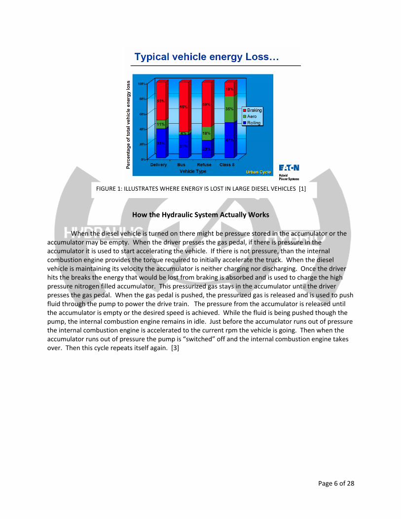
In Figure 1, you can see that when large diesel vehicles brake, the majority of energy is lost through the deceleration process. If the vehicle design can harness the lost energy and store the energy it can then be used to assist in the accelerating mode of the vehicle. The hydraulic hybrid system harnesses the lost energy by converting the momentum from the deceleration process into kinetic energy, which is then converted into pressure and stored in an accumulator. When the vehicle accelerates, the energy stored in the accumulator is released.
Page 6 of 28
How the Hydraulic System Actually Works
When the diesel vehicle is turned on there might be pressure stored in the accumulator or the
accumulator may be empty. When the driver presses the gas pedal, if there is pressure in the accumulator it is used to start accelerating the vehicle. If there is not pressure, than the internal combustion engine provides the torque required to initially accelerate the truck. When the diesel vehicle is maintaining its velocity the accumulator is neither charging nor discharging. Once the driver hits the breaks the energy that would be lost from braking is absorbed and is used to charge the high pressure nitrogen filled accumulator. This pressurized gas stays in the accumulator until the driver presses the gas pedal. When the gas pedal is pushed, the pressurized gas is released and is used to push fluid through the pump to power the drive train. The pressure from the accumulator is released until the accumulator is empty or the desired speed is achieved. While the fluid is being pushed though the pump, the internal combustion engine remains in idle. Just before the accumulator runs out of pressure the internal combustion engine is accelerated to the current rpm the vehicle is going. Then when the accumulator runs out of pressure the pump is “switched” off and the internal combustion engine takes over. Then this cycle repeats itself again. [3]
FIGURE 1: ILLUSTRATES WHERE ENERGY IS LOST IN LARGE DIESEL VEHICLES [1]

Page 7 of 28
Part C: Marketability
In America, the trend is to own your own car, so most Americans are concerned with the fuel
economy and emissions of their own personal vehicle and not of a city bus or a waste management truck. In highly populated countries like India, China, and Singapore, the trend is to take a bus or train because people cannot afford to own their own vehicle or the roads are too crowded because of highly populated areas. When people of these countries take the bus or train they are reducing the amount of emissions produced, but the busses used still produce a lot of emissions and do not work efficiently.
In Table 1, you can see that the number of large diesel vehicles in India is increasing each year. As the number of vehicles on the road increase so does the pollution which increases the need for fuel efficient vehicles. So to decrease the pollution why don’t more people from India, China, and Singapore just go out and buy new fuel efficient diesel vehicles? The answer is they can’t afford to buy brand new vehicles or even used vehicles. This is why a group of senior design students are designing a hydraulic hybrid system. The difference between our system and the system used on the America UPS trucks is that our system can be placed on an existing diesel vehicle. Our hydraulic hybrid system is a retrofit kit that can be purchased by itself and installed on any existing diesel vehicle that is in service. The goal of Czero is to be able to manufacture these retrofit hydraulic hybrid systems to less developed countries with high population concentration at a price they can afford. [4]
FIGURE 2: HYDRAULIC HYBRID DIAGRAM [3]

Page 8 of 28
Part D: How is Electrical Engineering Applied to this Project?
The majority of hydraulic hybrid system is related to mechanical engineering; however, a control system is what ties all the different parts of the system together. The control system allows all the parts of the diesel vehicle to work with the hybrid system in an efficient manner. Some control systems can be implemented using mechanical devices and methods, but since our hydraulic system is a retrofit kit we have to be able to fine tune each kit to the existing vehicle it will be attached to so the system will be operating at its highest efficiency. The team controls the displacement pump and safety controllers with MotoTron 128 ECU. The controllers are very self explanatory. One controls the displacement of the pump and the other controls the safety backup in case of a system malfunction. In order to design the controllers, an advanced knowledge of MATLAB, circuit design, and electrical control systems is required.
Part D: Budget
As you can tell our project can help the aide the current economic and environment issues. Due to the benefits of our project we are qualified for many grants. The senior design team initially budgeted $50k from Czero to get the project moving. Czero then received a $25k grant from the Colorado Governor’s Office. A local company, MotoTron, donated several ECU controller modules for the test skid and the truck. The multitude of funding has made this project possible.
TABLE 1: ILLUSTRATES THE RISING NUMBER OF LARGE DIESEL
VEHICLES ON THE ROADS OF INDIA [4]

Page 9 of 28
Section 2: Previous Team’s Work and Details of Hydraulic System
Part A: Getting Started
For the electrical engineering team, this project began in the spring semester of 2008. The project was originally a Mechanical Engineering senior design project that began in the fall semester of 2007. The first semester of this project, a large group of mechanical engineers began to think through the design of the hydraulic hybrid. Most of the semester was spent researching previous experiments and possible designs that could be applied to this project. Many Simulink models were created in MATLAB to predict the efficiency of the vehicle, what size of vehicle was needed, and how much pressure needed to be stored in order to supply sufficient power to the vehicle. Also in the fall semester of 2007, the group also purchased a “test skid” from the University of Michigan. The details of the test skid will be explained in detail in the following section.
There was relatively no electrical engineering work that was done on this project prior to the spring semester of 2008, however Michael Neuberg and Evan Vleck researched the best methods of controlling this system and came upon a local company in Ft. Collins called MotoTron. MotoTron designs controllers (ECU’s) for high performance vehicles. What made MotoTron the controller of choice was its seamless interface between the hardware and MATLAB. The only programming language that is needed is a working knowledge of Simulink, and the Simulink models can be directly downloaded to the controller. MotoTron agreed to donate the necessary supplies, software, and technical support to the project.
Part B: Previous Team’s Accomplishments
There was a tremendous amount of work that went into the controls design for the original team. The majority of the time and effort was spent understanding what was being controlled and why it needed to be controlled. In the Figure 3, there is a schematic of the hydraulic system which illustrates where all the items that need to be controlled are.

Page 10 of 28
The Hydraulic Hybrid system is broken down into two main controllers: the Safety Controller and
the Displacement Controller. The safety controller and the displacement controller both monitor the system for dangerously high speeds and pressures. If a read in speed or pressure exceeds set levels within the controller, the displacement controller is activated to react and attempt to adjust the displacement until the system reaches stability. Similar if the pressure in the accumulator increases too rapidly or reaches critical levels, the displacement controller will set the displacement pump so there is no pumping to the accumulator. Should the displacement pump not gain control of the system, or fail completely, the safety controller, which is a completely separate unit, will assume control of the system and turn off the hydraulic system. The safety controller will also release any pressure from the accumulator, and in our test case, applies the brakes to reduce any dangerous speeds.
Test Skid
The test skid is a displacement pump that is connected to a large flywheel (in order to simulate the load of the vehicle) and an accumulator. The Mechanical Engineer and Electrical Engineers used the test skid to perform all their initial tests and trials on. The test skid, although was not a true simulation of how the hydraulic system would behave on the truck, was an accurate means to test the designed control system. The test skid can be seen from various angles in Pictures 1 and 2.
FIGURE 3: SCHEMATIC CREATED BY SENIOR DESIGN TEAM

Page 11 of 28
The Truck
The truck used for the project was purchased by Czero and donated to the team in order to have an accurate model for the hydraulic system. It is a heavy diesel engine that will be similar if not exactly the same as the engines that the hydraulic system is designed for. The cargo box was removed from the truck in order to allow easy access to the drive shaft and undercarriage. This is necessary to attach all of the different components and allow the senior design students to see how the system is operating and if there are any visible or obvious safety hazards. The MotoTron controller is placed in the cab under the
PICTURE 1: TEST SKID WITH OUT COVER
PICTURE 2: TEST SKID WITH COVER. COVER IS FOR PROTECTION WHEN
THE FLYWHEEL REACHES HIGH SPEEDS

Page 12 of 28
passenger seat. All the outputs and inputs of the truck feed in or out of the MotoTron controller. Initially there was no available 48 pin controller to attach to in vehicle, so the safety controller from the test skid was moved into the truck in order to operate the vehicle safely. The hydraulic system was installed behind the cab of the truck by the mechanical engineers.
The truck has extensive wiring because internal
combustion engine, the displacement pump, the pressure transducers, and many other items need to be connected to the MotoTron controller. The MotoTron controller is powered by the truck battery. Figure 4 was designed so the senior design students could visualize how the truck should be wired. The wiring was a large task because both the test skid and the truck needed to be wired. The two wiring setups were very different. The test skid had many different pressure monitors and speed sensors that were used to collect initial data, but the truck does not have these sensors. This means the wiring is somewhat simpler on the truck. There were still difficulties with the truck wiring. Two wiring challenges that arose were the controller needed to be powered reliably off of the truck battery and the wire had to routed through the truck so they do not interfere with the normal operation of the truck.
PICTURE3: HYDRAUILIC PUMP BEHIND TRUCK CAB PICTURE 4: DIESEL TRUCK THE SENIOR DESIGN
TEAM ATTACHED THE HYDRAULIC SYSTEM TO
FIGURE 4: INPUTS AND OUTPUTS TO THE
CONTROLLER

Page 13 of 28
Safety Controller
The test skid has a safety controller integrated into it that limits the fly-wheel from going over 2000RPMS. This is primarily to protect people standing around and to also prevent the test skid from getting damaged incase a malfunction does occur. When the skid spins above 2000RPMs the solenoids will release and the hydraulic fluid will push on the emergency brake pads to slow the fly-wheel.
The gas pedal input is the result of a magnetic pickup going into the crank signal input of the controller. This is done using a MotoTron 48 pin controller which isolates it from the other controller and will always be operational. The team first attempted to hook the gas pedal input into the MotoTron controller by using an S-function block in Simulink. The purpose of the S-function was to read in the RPM values every 10 ms and then store the values in an array of size 1x200. If over 90% of the values entred were over 2000RPMS then the emergency brake system would activate. The time it took to sample this array took two seconds. So many samples were taken in case there were small spikes of noise which result in inaccurate readings. With this size of array and sample time the skid would have to have 180 out of 200 samples to be over 2000RPMS.
The samples are always updating in that it would push out the last sample and shift all the others to make room for the new sample every 10ms. This is similar to a last in-first out, LIFO, array structure. The sampling method showed if the fly-wheel was consistently over the RPM limit and that the reading was accurate and not just noise. As said before this was all done in standard Simulink and not implemented in MotoTron.
The system worked great in this simulation; however there were problems compiling the Simulink model in MotoTron. First, the S-function needed to be a discrete S-function and not in continuous time. Even after this was changed the Simulink model did not compile. The senior design team had to contract MotoTron to resolve the problem. The solution was to include files that were mission. Even after the files were included, Simulink would not compile. A solution was needed quickly due to the time crunch of getting the test skid up and running.
The team’s next idea was to try and implement the safety controller with standard Simulink blocks with no S-functions. This idea was implemented using many switch blocks and discrete delays. The new system, Figure 5, would read in the speed and if it was over 2000RPMS would output one value or if not the system would output different value. The same speed input was then delayed in increments of 250ms three times and the same logic was applied. With this system only four speed samples were taken over the course of 750 ms. When all four samples were over 2000RPMs then the emergency brake system would be applied. This method worked successfully, but was not as accurate because fewer samples were taken.

Page 14 of 28
Safety System
Another problem that was encountered with the displacement controller was when an over speed was detected then the brakes would be applied, but then when the RPMs went below 2000 then the brakes would release. In order to keep the brakes applied more logic needed to be implemented. The solution can be implemented by ‘tricking’ the speed input. When the brakes are applied then the speed sensor input is taken away and a constant input of 2100RPMs is applied even though the system is actually slowing down. This way the system thinks that the RPMs are still above 2000RPMs and the brakes will be kept on. The only way to over ride this is to reset the system by turning it off. Overall, the newly implemented system proved to be very reliable and has been in operation since it was implemented.
Solenoid Valves
Three solenoid valves are being used in the hydraulic system. On the test skid the solenoids are
rated at for 12 V at 6.4 Ω. From this it is determined that 1.8 Amps or approximately 2 Amps are needed to flip the solenoids on or off. The solenoids are switched by using the injector driver outputs from MotoTron Simulink. On terminal of the solenoids are attached to the truck battery that supplies 12 V. The other terminal is connected to the injector drivers on the MotoTron controllers. The injector driver acts like a BJT switch. The solenoid is triggered off by applying a digital zero value. When the solenoid is triggered off it behaves as a floating circuit with no voltage across it. When the solenoid is triggered on a digital one value is applied. The injector driver connects the circuit, grounding it, which completes the circuit. The solenoid then turns on with a voltage of 12 V applied across it.
An example of how the solenoids would operate is when the emergency brake is applied. In normal operation the solenoids are on which doesn’t allow fluid to flow to the brake pad. When the brakes need to be applied the solenoids turn off; which lets the fluid push on the brake pads.
FIGURE 5: SAFETY CONTROLLER

Page 15 of 28
Motor Controller
When the team was conducting their initial tests, the HB-25 controller was used to control the DC motor. One purpose of the displacement pump is to control the DC motor that changes the displacement. The DC motor has reverse polarity inputs to change directions. The decision to use a motor controller was made for many reasons. First, the speed that the DC motor would rotate at could be varied. Second, it is able to reverse the polarity of the motor without physically changing the system. Last, it allowed a way to interface the DC motor to the 128 pin controller and actually have control over it rather than just being on or off.
The DC motor controller brand is Parallax model number HB-25. This motor controller has a
high current motor driver chip, which is basically just an H-bridge setup. The great thing about this design is it is rated for up to 30 Amps, where our DC motor pulls a max of 25 Amps on surge and 20 Amps normally. Therefore, the current is not limited with this motor controller. Also, the controller has a fan built in on the bottom to pull heat away from the chip. It also operates similarly to a servo motor making it easy to operate. Operation of this motor controller involves the following steps. MotoTron Simulink blocks can be used to select the desired frequency and duty cycle of the output.
Pulsed inputs to the controller were first tested on an oscilloscope to determine the correct Simulink PWM block input in order to get the correct pulsed outputs to the motor controller. To operate the device a 1ms, 1.5ms, and 2ms pulse every 20ms is needed to run the DC motor in full reverse, stop, and full forward respectively. All values in between can be used at lower speeds. For example a 1.7ms pulse every 20ms would run the motor slowly in the forward direction. This way the user can control the direction and speed of the motor simply through software. This is achieved because the motor controller also outputs a PWM signal to the DC motor. This is just a straight 9.2 kHz signal that varies the current allowed to the DC motor. Therefore, instead of the DC motor using a straight current source, it gets small amounts of current at the rate of 9.2 kHz. In final operation a preset frequency of 40Hz was used to guarantee the 20ms delay between pulses needed. Through the displacement controller logic only the duty cycle was adjusted to operate the DC motor.
Transfer Case
The transfer case is what changes the truck between 2WD, 4HI, 4LO, and Neutral. It is desired to be able to control the transfer case through MotoTron. The transfer case has four inputs from an encoder that reads in a high or low value. Inside the transfer case there is a DC motor that can be turned to a desired position.
PICTURE 5: HV-25 MOTOR CONTROLLER

Page 16 of 28
To be able to change the displacement of the transfer case, inputs need to be checked by using the MotoTron controller. For the transfer case controller to work properly a pull-up resistor needed to be installed. The high and low values read by the encoder on the transfer case are between 0 V and 5 V depending on where the DC motor is positioned. In the software this corresponded to a 10bit A2D value represented by 0 or 1023. An obstacle encountered was the encoder didn’t follow a standard 4 element truth table.
The problem is that it was not a standard truth table. For example sensor A has 9 high inputs. This logic was done in Simulink using combinatorial logic. The truth table had to be written to match up with the standard parameters. The reordered logic now goes C, A, B, D, giving each state a different output value. Then this could be compared to the user input value through the use of an if-else statement. When the corresponding if-statement was true then it would output a command. This command is to either turn the DC motor forward, stop, or reverse. The same motor controller used for the DC motor of the test skid was used in this. All that was needed to be output was a different duty cycle in order match up the desired input with the actual input. To actually utilize this method, the user will input the desired gear position for example, 2WD. Then the controller looks at where it is and then rotates the DC motor until it reaches the desired state. The amount the motor would have to rotate between different stages is approximately 20:. Part of the design of the system was to have the DC motor rotate at a slow speed. This will take longer to get to the desired location, but it will reduce the amount of overshoot and increase stability. Also since the wheel is very small and only has 20: or approximately ½” to turn from position to position the wheel still only takes milliseconds to reach its designation. The following schematic shows how the transfer case will be implemented in hardware on the vehicle.
FIGURE 6: TRANSFER CASE TO CONTROLLER SCHEMATIC
Page 17 of 28
Displacement Pump Controller
Controlling the displacement of the hydraulic pump is critical to the operation of a hydraulic-hybrid vehicle. Its importance lies in the fact that the displacement of the hydraulic pump governs how the vehicle behaves like a hybrid. The torque on the axel of the vehicle due to the hydraulic system is proportional to the pressure difference between the high-pressure and low-pressure accumulator times the displacement of the hydraulic pump. A torque on the axel accelerates or decelerates the vehicle making control over the displacement very important. For the hybrid, the accumulator pressure is not regulated; therefore the torque applied to the axel via hydraulics is controlled solely by adjusting the displacement. The displacement of the hydraulic pump is dictated by the position within the pump and is variable.
A higher level system controller will determine the appropriate displacement based on the pressure in the accumulators, the speed of the vehicle, the driver’s position on the gas pedal, and perhaps other factors. By evaluating these conditions, the higher level controller will command the displacement controller to a given displacement. The displacement can be positive, negative, or zero allowing for torque to accelerate, decelerate, or add no torque from the hydraulic system. With positive displacement, the pump acts like a motor, allowing hydraulic fluid to flow from the high pressure accumulator to low pressure, accelerating the vehicle. With negative displacement, the pump acts like a generator, pushing fluid back into the high pressure accumulator and decelerating the vehicle in the process.
Implementation of Control Algorithm on Test Skid
The control algorithm is implemented on the 128-pin MotoTron controller using the MotoHawk software, which runs in MATLAB. Simulink, is used to design the control algorithm with some additional MotoHawk tools. The model is then built and downloaded into the MotoTron board.
The displacement pump on the test skid was adjusted by moving the internal head from side to side. The middle was zero displacement, to the right was positive displacement, and to the left was negative displacement. This head was moved by cranking a shaft in the proper direction. To move the shaft, a high-torque geared DC servomotor was purchased and coupled to the crank shaft.
The first step to controlling the displacement pump head was to measure the actual position so the feedback can compensate for any distortion. After exploring several options, it was decided to use a 20-turn, 10 kΩ potentiometer for feedback. The potentiometer was mounted on the same shaft with the DC motor and crank. This way the resistance varies linearly as the displacement pump head is changed as the shaft is cranked. To measure the potentiometer, a 5 V pin from the MotoTron controller was connected to the potentiometer and the voltage output from the potentiometer was wired to an analog input on the MotoTron controller. A high impedance pull down input pin was used after it was discovered that a low impedance pull up input pin made the voltage non-linear due to loading. In MotoHawk, an analog input block with the correct pin selected and the output in counts 0 to 1023 (1023 = 5 V) is normalized such that full positive displacement is 1, full negative displacement is -1, and no displacement is 0. For accurate feedback, calibration is necessary.
For calibration and data logging, MotoTron has a software tool called MotoTune. MotoTune is a software program that runs while the actual controller is active and can actively monitor any probe setup in MotoHawk, log the incoming data in real-time, and change the value of the output of any calibration block setup in MotoHawk to a user-designated value. To calibrate the feedback and

Page 18 of 28
ensure proper normalization, the shaft was hand-cranked to the left and right limits and the analog input count values were saved as constants called Left_Lim and Right_Lim in an m-file. These endpoints are set to -1 and 1 displacement and any value that lands between is linearly extrapolated.
To move the DC motor, a PWM (Pulse-Width Modulated) chip was used in conjunction with a 12 volt car battery. The battery’s terminals are connected to the PWM chip which then connects to the leads on the DC motor. The PWM is also connected to a PWM output pin on the MotoTron controller. Different PWM signals (duty cycle and frequency) sent to the PWM chip allow for the PWM chip to output anywhere between -12 volts to 12 volts to the DC motor. The PWM output block in the MotoHawk toolbox was fed a constant of 4000 for the PWM frequency and the duty cycle value was varied to produce different voltages at the DC motor terminals and allow change in displacement. The duty cycle value that moves the DC motor at a maximum velocity to the left is -3762, the duty cycle value that moves the DC motor at maximum velocity to the right is -3925, and -3842 is the duty cycle value that outputs 0 volts to the DC motor, making the DC motor stop.
Implementation of Control Algorithm on the Truck
The truck is a nearly identical setup to the test skid with a few differences. The displacement pump is adjusted using hydraulic pressure rather than a DC motor attached to a crank shaft. With no DC motor, there is no PWM chip necessary. There are two solenoid valves on either end of the rod-like displacement pump and one is opened while the other is closed to move the displacement a particular direction. To open and close these valves, injector driver output pins are used on the MotoTron controller. This concept is fundamentally the same as the control algorithm used in the test skid controller. Another difference is the truck’s displacement pump has 3 digital outputs that are active when the displacement pump is full positive, full negative, and zero. This should allow for real-time calibration with 3 data points rather than the 2 used on the test skid. A potentiometer is also used for feedback on the truck’s displacement controller; however, it is only a half-turn potentiometer.
Section 3: Current Teams Work
Part A: Milestones
All electrical connections were tested, verified, and replaced if needed. Currently only one operator is required to drive the truck. The Simulink code for the displacement pump from the previous team was rewritten to be optimized. The team is able to track the position of the displacement pump head. Series serial data communication was established between the truck’s engine control module (ECM) and the MotoTron engine control unit (ECU). Improvements were made to the transfer case Simulink model. The MotoTron controller and the hydraulic pump can be activated without powering the truck. A simulation of rough automation of the hydraulic system was accomplished.
Part B: Improvements to Previous Team’s Work
Electrical Connections
Last semester’s team was rushed for time so they did not have a chance to wire the MotoTron ECU effectively. When the current team started the display of organized wires was very discouraging. The first goal for the semester was to rewire the truck in an organized manner. This included one

Page 19 of 28
continuous piece of wire going from the output of the truck to the input of the MotoTron ECU with functional crimps, color coding the wires for their specific purpose, and having the correct length and gauge of wire. After this was accomplished the team could work on the ECU more efficiently.
Manual Switches
At the beginning of the semester the hydraulic system on the truck needed two operators. One would drive the truck and the other would perform the switching operations. The driver initially needed to build up pressure. The driver would do this by driving around the EECL parking lot while the second person looked out the back window at the small pressure gauge. The pressure gauge usually displayed the correct amount of pressure that was in the accumulator. Once there was enough pressure build-up the driver would take their foot off the gas pedal. The second operator pushed a hot key of the computer to activate the hydraulics. While the internal combustion engine was idling the truck would accelerate with hydraulic power. The second operator had to continuously watch the amount of pressure in the accumulator because the hydraulic system does not run smoothly on low amounts of pressure. When the pressure was approaching a dangerously low level the driver would reengage the engine. The second operator would push another hot key on the computer to turn the hydraulic system off. The driver then has to put the truck in drive to rebuild up pressure. The two operators were needed because the hot keys on the computer were too small and hard to hit while the truck was jerking around. Our goal at the beginning of the semester was to have one operator drive the truck and be able to switch between the modes. The physical design included two mechanical switches. The first switch was to activate the hydraulic system or to deactivate the hydraulic system. When the hydraulic system is activated the truck operates as a hybrid. When the hydraulic system is deactivated the truck operates normally. The second switch allowed the operator to tell the system to charge or discharge the accumulator. In order for both switches to control the system Simulink code needed to be implemented. The code reads in the inputs from the switches and then either turns on or off the hydraulic system. If the hydraulic system switch is on the on position the code then controls the discharging and charging of the accumulator depending on the second switch position. The switches and code were implemented in the truck and work successfully. Now one person can drive the truck and the other is free to enjoy the ride or run tests without having to worry about the switching procedure.
PICTURE 6: MOTOTRON ECU WIRING
Page 20 of 28
Displacement Pump Controller
After the implementation of the two mechanical switches the truck operated as a bang-bang system. The bang-bang controller allows the driver to provide 100% charge resulting in deceleration or 100% discharge resulting in acceleration based on the position of the displacement pump head. The bang-bang system obviously got its name because the switching process jerks the truck. We needed a system that could control the amount of hybrid acceleration and deceleration by limiting the amount of torque supplied by the internal combustion engine and the hydraulic pump. The displacement pump head tracking controller allows the driver to request the desired amount of charge or discharge displacement allowing a smoother transition.
We found out a couple key issues with the current configuration of the displacement of the pump and the problems associated with not enough pressure in the lines. For instance, when the pressure in the accumulator becomes depleted the pumps displacement head is unable to move due to the lack of pressure pushing against the head. This causes an error in the controller that can ramp up the error correction term to a point that can damage the displacement head. Once the pressure is regained the controller will try to compensate for the large accumulated error and slam the head to the other side which is unsafe for fast driving conditions and can severely injure the driver. In order to fix this problem we implemented a safety controller to check the pressure remaining in the accumulator and compensate for the amount of control allowed. Once we started to get a feel for how the system operated we were able to start designing the controller that would directly correlate the throttle control with the displacement of the pump head.
The controller has two inputs and two outputs. The two inputs are the current position of the displacement pump head and the desired position of the displacement pump head. The two outputs are two digital signals that send information to the top and bottom displacement solenoid valves which adjust the displacement pump head to arrive at the desired position.
The algorithm for the displacement pump controller starts by reading in the potentiometer feedback which determines the current position of the displacement pump head. It then reads in a user input for the desired displacement pump head position. A difference of value is then derived from the two inputs. If a positive difference occurs the bottom solenoid is turned on until the desired position of the displacement pump head is reached. If a negative difference occurs the top solenoid is turned on until the desired position of the displacement pump head is reached. In the algorithm, there are error bands placed around the desired position to take into account slight changing of the feedback values at steady state.
Using a two mode throttle pedal, we split the percentage of desired torque to -100% to 0% to 100% with 0% at an initial offset in degrees from the neutral position. This enabled us to accurately predict what the driver desired, eliminating a lot of the guess work and use of the brake pedal. From this type of controller we were able to create a controller that would relate the desired percent of torque to the available torque in the hydraulic fluid and compensated the rest with the trucks engine. A large portion of time will be to accurately depict what the driver want verses how fast we get to his desired torque. Moving the displacement head too quickly will feel like the breaks were slammed on for charging mode or flooring it when in discharge. This is where a look up table will come in handy after we obtain data from our initial voyages. From this data we can create code that will use a hierarchy design for controlling what mode to run producing the best results. The shell for the code is in place with more information to accurately control the truck for next semester.
The controller works as desired when the vehicle is moving in a smooth and steady motion. However when conditions force the vehicle to shake violently, such as on driving on a rough surface, undesired overshoot is created in response.

Page 21 of 28
FIGURE 7: DISPLACEMENT PUMP HEAD POSITION VS TIME (IN ROUGH CONDITIONS)
FIGURE 8: DISPLACEMENT PUMP HEAD POSITION VS TIME (IN SMOOTH CONDITIONS)
Currently, the team is evaluating the issue that would cause the undesired overshoot in rough
driving conditions. A possible idea for the cause of the issue is that the displacement pump head shakes violently which results in inconsistent feedback readings. It could also just be a normal behavior for the displacement pump head during rough conditions. In either case the tracking controller needs to be optimized to take these effects into consideration.

Page 22 of 28
Serial Communication
In order to obtain information vital to the functioning and safety of a control system for the integrated hydraulic system in the International truck, deciphering and extraction of data from the serial data link was required module in this project. Automotive mechanics often use a diagnostic port to determine past and current parameters of the vehicle when investigating malfunctions in the operation. A wide variety of system parameters such as engine speed, oil pressure, fuel economy, battery potential, engine temperature, output torque, road speed, and total vehicle distance are transmitted over the serial data link. The number of times per second data regarding a specific parameter is transmitted, depends directly on the priority of that parameter. For example, oil temperature may be transmitted once in a given second while engine speed maybe transmitted ten times in a second. Two reasons for this prioritization are that engine speed is of greater importance to the system functionality than the oil temperature and due to the physical properties of oil, the temperature of the substance will not change quickly.
Depending on the manufacturing company, and even the model of the vehicle, different protocols are used when transmitting the serial data. Our International truck transmits data over a RS-485 cable using a J-1708 protocol. Along with the traditional structures of serial data such as start, stop and parity bit, the J-1708 protocol has a data structure specific to itself. Data pertaining to a specific parameter is preceded with a PID code. This PID is an identifier that indicates what property the data pertains to. Following the PID, data of varying lengths regarding the parameter is transmitted until a stop bit is received and data regarding a new parameter begins transmitted. It is important to take into account the bit resolution and initialization point when analyzing data. Bit resolution refers to the incremental amount in units of the parameters represented by an increase of one in the binary data. The initialization point is an arbitrary starting value for when the binary representation is zero. Depending on the parameters, the initialization points maybe a non-zero number.
Sample (Seconds)
Speed (mph)
FIGURE 9: ROAD SPEED VS TIME

Page 23 of 28
After conducting several driving tests and simultaneously collecting serial data our team was able to collect enough data to create the speed vs. sample plot shown above in Figure 9. After identifying the PID that represents road speed in the data, we extracted the two bytes of serial data following each PID identifier. After extracting all data relevant to the road speed for the duration of the driving test, we converted the binary data into the standard decimal values. The final step was to multiply the collected data by the bit resolution and adding the result to the initialization point for that specific parameter. The results in the plot above agreed closely with data collected from the speedometer for the duration of the test.
After conducting the driving tests, our team was able to verify the accuracy of the data supplied by the serial data port. Future plans involving serial data communications include first, creating code programs to efficiently extract and convert data from a wide variety of system parameters into a readable and easily verifiable text file. Secondly, developing a code of Mototron blocks that would read a variety of data into the Mototron ECU in real-time and convert this data in order that it can be used in the control algorithm for the motor and hydraulic system of the International truck.
Transfer Case
The transfer case changes the truck between 2WD, 4HI, 4LO, and Neutral gears in respect with the driveshaft. It is desired to be able to control the transfer case through MotoTron. With the current hybrid system, the position of the transfer case determines whether the truck is in hybrid mode or purely using the truck’s engine. The transfer case controller controls the transfer case motor which interfaces between the transfer case gears and the MotoTron controller. The transfer case motor has two inputs and four outputs. The two inputs can be supplied forward or reverse polarity of 12V in order to turn the motor clockwise or counter clockwise. The four different gears/position of the transfer case are positioned approximately 20: from each other. The four outputs provide a feedback that shows the angle at which the transfer case motor is currently positioned at.
FIGURE 10: DIAGRAM OF TRANSFER CASE
Page 24 of 28
The initial road block the team encountered regarding the transfer case was getting the motor to move clockwise or counter clockwise. The motor wouldn’t respond to 12V as expected. Many tests were done to determine the issue. It wasn’t clear what exactly the motor required in order to get a response. Several types of inputs were tried; constant voltage signals, pulse signals, and PWM signals. All of these test signals failed to induce a response. Then the team inquired about getting another transfer case motor from the mechanical engineering team. This solved the first problem. The motor the team was initially provided with was broken. The second roadblock is still ongoing. There are problems getting proper feedback from the four output ports of the transfer case motor. At first there was confusion between the use of pull down resistors and pull up resistors and which one the motor requires. After the team deduced from several different sources that the motor requires a pull down resistor, there was still no response from the feedback. The team is currently looking into going to a Dodge dealership to see if they can provide more information regarding the feedback system, and possibly test whether the transfer case motor is in proper working condition.
Illuminated Switch
There was a desire to operate the hydraulic system without turning on the internal combustion engine. The problem with this was the MotoTron ECU is powered by the battery of the truck. We wanted an easy transition to turn the hydraulic system on and off without turning the key on and off. An illuminated switch was installed do the driver can easily see if the MotoTron ECU can be controlled. If the switch is illuminated, the hydraulic system will function independent of the internal combustion engine whether the ignition key is turned. This also means if the internal combustion engine is not on the power steering and other engine powered functions will not work.
Section 4: Current and Future Automation Process
Part A: Current Status
In order to optimize the control of the vehicle, there must be an accurate way of measuring the driver's desire of acceleration, velocity, and deceleration. The hydraulic system is altering the normal operation of the engine by interrupting the gas pedal signal and sending the engine an artificial gas pedal signal. The artificial gas pedal signal is constructed from the difference of torque available from the hydraulic system and the torque needed to accelerate at a given rate. Since the two different sources are used to supply torque there must be an accurate way of measuring the total amount of torque desired. Because the overall performance of the hydraulic system is based on the ability to transfer velocity into hydraulic pressure, the controller must take every opportunity to charge the accumulator. Thus the challenge is to decide when to charge the accumulator, when to discharge the accumulator, and for each case, what magnitude is the operation performed. There are many ways to approach the challenge of determining the driver's desire. For this design we have chosen to gather data to determine the driver desire from the throttle (gas) pedal only. Although collecting data from the brake pedal will give good feedback as to when the driver would desire to stop or decelerate, the decision has been made to neglect the brake pedal in a desire to not jeopardize the safety of the system. We do not want the brake to interfere with the hydraulic system because the brake pedal could act inconsistently. Even in the case the brake pedal itself was not tampered with and only feedback from a sensor on the pedal was gathered, there is the possibility the brake would dynamically respond to the anticipated driver's desire and thus not perform as a normal

Page 25 of 28
brake. This would be problematic when the driver would need to use the brake in an emergency, but the controller was not anticipating the stop and would not apply the brake. Thus the decision has been made the brake pedal will be ignored for this design and only be used when an emergency stop is needed by the driver. Throughout the semester, there was much discussion about how to design the controls that predict the desire of the driver. Some of the controls must be predictive and interpretive, however some of the controls must also be very standard and linear; what the driver does, the driver gets. This works well for accelerating the vehicle. As the driver presses the throttle down, the controller is able to know exactly how much torque is needed, and then can calculate the needed torque from the hydraulics and supplement the rest with torque from the engine. However, as the driver reaches the desired velocity, the throttle pedal must be let up due to the fact that less torque is required to maintain a constant velocity than is required to accelerate. In such a case, the controller must know and understand that the driver does not wish to decelerate, however the driver wishes to maintain the current velocity. The controller can achieve this information by looking at the history of pedal displacement as well as current road speed and the change in road speed over time. This task is a very challenging and advanced procedure in order to accurately determine all of the parameters and apply it in a safe and transparent manor for the driver. Thus the decision was made to alter the function of the gas pedal to operate as a throttle controller and hydraulic brake.
Part B: Future Plans As Shown in Figure 11, the full range of the pedal is broken into three positions, charge, neutral, and discharge. In each of these positions, the driver will have the ability to control the speed in a fashion that is close to normal driving while still allowing the controller to easily interpret what the driver is doing and what the driver wants. It is understood that the driver will need to learn and adapt to the new method of driving, however with this setup, the controller can safely and easily apply the correct torque to the engine as well as begin charging before the brake pedal is ever pressed. This design is only in concept and simulation at this point in the project and has yet to be tested on the physical hardware. It is understood that there may be major modifications made to this design when it is observed during a normal drive cycle.

Page 26 of 28
When the pedal is at zero displacement, it is considered to be in the full charging mode. When the driver wishes to stop, the driver will lift out of the throttle in order to move their foot to the brake pedal. By performing this action, the pedal will enter the charging mode before the driver ever presses the brake, thus allowing for the maximum energy recovery, and possibly decelerating the vehicle at a fast enough rate for the driver’s desire, thus eliminating the need for the brake in certain circumstances. This mode, although activated by the pedal position, will be dependent on the speed of the vehicle. For instance if the vehicle is stopped, then there is no need to charge the accumulator no matter where the pedal is located in the charging zone. In fact, the error check of vehicle speed for this mode is crucial because the vehicle is not accelerating or remaining at a constant velocity the charging mode is engaged. The pressure from the displacement pump will actually accelerate the vehicle in reverse which is a very dangerous situation. The controller will compare road speed to the charging pedal position in order to determine how to set the displacement. Unlike the discharging mode, the charging mode is allowed to charge no matter what the pressure in the accumulator is. There is a mechanical pressure relief valve in line with the hydraulic system that will make it impossible to "overcharge" the accumulator, thus allowing for infinite hydraulic breaking. This makes for an easier controller because the pressure of the accumulator does not have to be monitored in this mode and it allows for a maximum charging of the accumulator. The next mode that is available from the throttle pedal is the neutral zone. This is a relatively small zone that is identical to zero pedal displacement in a normal vehicle. When the pedal is pressed to this level, the truck will "coast" with its own momentum and not apply any acceleration/forward torque or charging/reverse torque. This position will need extensive testing in order to determine the tolerance so that the driver can easily enter this mode without accidently entering the charge or discharge mode. At this pedal position, the displacement pump will be set to zero so no charging or discharging occurs. In the last mode, discharge, the pedal will operate as a normal throttle (gas pedal). The driver will press the pedal to achieve a desired torque that is a combination of hydraulic and truck engine torque. In this mode, the controller will have to make many intelligent decisions based on the position
CHARGE
NEUTRAL
DISCHARGE
FIGURE 11: GAS PEDAL MODEL

Page 27 of 28
of the throttle, such as the available pressure and the available engine torque. The pressure in the accumulator has a minimum that cannot be breached without damaging the accumulator; the controller must monitor the pressure as it applies hydraulic torque. Also the controller must send an artificial signal to the engine so the engine can supplement torque as the hydraulic pressure decreases. As the pedal is pressed more and more, the amount of displacement will increase as will the engine torque. The controller will allow the engine to rev in order to seamlessly transfer between full hydraulics, to a combination of hydraulics and truck engine, to only truck engine. Because the controller is able to obtain nearly all of the information that it needs from the position of the throttle, the hydraulic system will be able to perform optimally in all conditions such as driving up and down hills. As mentioned before, this control system is only in the concept stages and will be implemented in the following semester. Although some modifications to the design might be made, the overall idea and design have been discussed at length and it is believed to be the best short term and long term solution for controlling the hydraulics of the vehicle.
Page 28 of 28
References *1+ Eaton. “Hybrid Power Systems: Hydraulic Launch Assist HLA System.” 2007. Retrieved on
December 4, 2008, from http://files.harc.edu/Projects/HybridTrucks/HydraulicLaunchAssistSystem.pdf
[2] Parker. Retrieved on December 4, 2008, from www.parker.com. [3] UPS. “Fact Sheets: UPS in Industry to Purchase Hydraulic Hybrid Vehicles.” Retrieved on December
4, 2008, from http://www.pressroom.ups.com/mediakits/factsheet/0,2305,1315,00.html *4+ Singh, Sanjay. “Review of Urban Transportation in India.” 2005. Retrieved on December 4, 2008,
from http://www.nctr.usf.edu/jpt/pdf/JPT%208-1%20Singh.pdf