HYDRAULIC HAMMER RAMMER 3288 PRO - portal.sandvik
76
Original instructions 0/16 OPERATOR'S MANUAL OM3288PROENG.016 HYDRAULIC HAMMER RAMMER 3288 PRO
Transcript of HYDRAULIC HAMMER RAMMER 3288 PRO - portal.sandvik
Original instructions
0/16
OPERATOR'S MANUAL
OM3288PROENG.016
HYDRAULIC HAMMERRAMMER 3288 PRO
OPERATION. . . . . . . . . . . . . . . . . . . . . . . . . . . 31. Foreword . . . . . . . . . . . . . . . . . . . . . . . . 4
Important safety information . . . . . . . . . 4Warranty. . . . . . . . . . . . . . . . . . . . . . . . . 4Spare part orders. . . . . . . . . . . . . . . . . . . 5
2. Machine numbers . . . . . . . . . . . . . . . . . . 6Model and serial number . . . . . . . . . . . . 6
3. Product introduction. . . . . . . . . . . . . . . . 7Overview. . . . . . . . . . . . . . . . . . . . . . . . . 7Removal from package . . . . . . . . . . . . . . 7Lifting instructions . . . . . . . . . . . . . . . . . 7Main parts . . . . . . . . . . . . . . . . . . . . . . 11Ramvalve . . . . . . . . . . . . . . . . . . . . . . . 12Greasing device . . . . . . . . . . . . . . . . . . . 12Service indicator . . . . . . . . . . . . . . . . . . 13Environmental protection and recycling policy . . . . . . . . . . . . . . . . . . . . . . . . . . 13
4. Safety . . . . . . . . . . . . . . . . . . . . . . . . . . 14General safety . . . . . . . . . . . . . . . . . . . . 14Safety instructions . . . . . . . . . . . . . . . . . 14
5. Optional equipment . . . . . . . . . . . . . . . 23AGW unit . . . . . . . . . . . . . . . . . . . . . . . 23Ramlube . . . . . . . . . . . . . . . . . . . . . . . . 23Ramair II. . . . . . . . . . . . . . . . . . . . . . . . 24Water jet . . . . . . . . . . . . . . . . . . . . . . . . 24
6. Operation . . . . . . . . . . . . . . . . . . . . . . . 26Operating instructions. . . . . . . . . . . . . . 26Daily operation . . . . . . . . . . . . . . . . . . . 35Mounting and dismounting the hammer 40Movement. . . . . . . . . . . . . . . . . . . . . . . 41Special conditions of use . . . . . . . . . . . . 42Storage . . . . . . . . . . . . . . . . . . . . . . . . . 42
LUBRICATION . . . . . . . . . . . . . . . . . . . . . . . . 431. Hammer tool greasing. . . . . . . . . . . . . . 44
Recommended greases. . . . . . . . . . . . . . 44Manual greasing . . . . . . . . . . . . . . . . . . 44Automatic lubrication . . . . . . . . . . . . . . 45
2. Carrier hydraulic oil . . . . . . . . . . . . . . . 46Requirements for hydraulic oil . . . . . . . 46Oil cooler . . . . . . . . . . . . . . . . . . . . . . . 48Oil filter . . . . . . . . . . . . . . . . . . . . . . . . 49
MAINTENANCE . . . . . . . . . . . . . . . . . . . . . . . 511. Routine maintenance . . . . . . . . . . . . . . 52
Overview. . . . . . . . . . . . . . . . . . . . . . . . 52Inspection and maintenance bythe operator . . . . . . . . . . . . . . . . . . . . . 52Inspection and maintenance by the dealer . . . . . . . . . . . . . . . . . . . . . . . 53Disassembling and assembling housing covers . . . . . . . . . . . . . . . . . . . . . . . . . . 54
2. Changing the tool . . . . . . . . . . . . . . . . . 56Wear limits and lubricants fortool removal . . . . . . . . . . . . . . . . . . . . . 56
Removal of tool . . . . . . . . . . . . . . . . . . 57Installation of tool . . . . . . . . . . . . . . . . 58
3. Bronze insert of TS bushing . . . . . . . . . 59Wear limits for bronze insert of TS bushing . . . . . . . . . . . . . . . . . . . . . . 59Removal of bronze insert . . . . . . . . . . . 60Installation of bronze insert . . . . . . . . . 62
4. Troubleshooting . . . . . . . . . . . . . . . . . . 64The hammer does not start . . . . . . . . . . 64The hammer operates irregularly but the blow has full power . . . . . . . . . . . . . . . 65The hammer operates irregularly and blow has no power . . . . . . . . . . . . . . . . . . . . 65Impact rate slows down . . . . . . . . . . . . 65The hammer does not stop or has run-on . . . . . . . . . . . . . . . . . . . . . . . . . 66Oil overheats . . . . . . . . . . . . . . . . . . . . 66Recurrent tool failure . . . . . . . . . . . . . . 67Further assistance . . . . . . . . . . . . . . . . . 67
SPECIFICATIONS. . . . . . . . . . . . . . . . . . . . . . 691. Hammer specifications . . . . . . . . . . . . . 70
Technical specifications . . . . . . . . . . . . 70Main dimensions . . . . . . . . . . . . . . . . . 71Mounting bracket specifications . . . . . . 71
2. Tool specifications . . . . . . . . . . . . . . . . 723. CE mark and EC Declaration of
Conformity . . . . . . . . . . . . . . . . . . . . . 73

Operation - Page 3COPYRIGHT © 2016 SANDVIK MINING AND CONSTRUCTION OY
3288 PRO
OPERATION
COPYRIGHT © 2016 SANDVIK MINING AND CONSTRUCTION OYPage 4 - Operation
Foreword 3288 PRO
1. FOREWORD
1.1 IMPORTANT SAFETY INFORMATION
Basic safety precautions are outlined in the "Safety" section of this manual and inthe description of operations where hazards exist. Warning labels have also been puton the machine to provide instructions and to identify specific hazards which if notobserved could cause bodily injury or death to you or other persons. These warningsin the guide and on the machine labels are identified by the warning symbol.
To use the attachment correctly, you must also be a competent operator of the carriermachine. Do not use or install it if you can not use the carrier machine properly. Theattachment is a powerful tool. If used without proper care, it can cause damage.
Do not rush when you are learning to use the product. Take your time and mostimportantly, take it safely. Do not guess. If there is anything you do not understand,ask your local dealer.
Improper operation, lubrication or maintenance of this machine can be dangerousand could result in injury.
Do not operate this machine until you have read and understood the instructions inthis manual.
Do not perform any lubrication and maintenance on this machine until you haveread and understood the instructions in this manual.
1.2 WARRANTY
Check that a separate warranty sheet explaining the export warranty terms isdelivered with the attachment. If not, contact your local dealer immediately.
WARRANTY REGISTRATION CARD
A warranty registration card is filled out after the installation inspection by thedealer and a copy of it is sent to the manufacturer. This card is very importantbecause no warranty claims are handled without it. Make sure that you get a copyof it after the installation inspection and that it is correctly filled out.
INSTALLATION INSPECTION
An installation inspection must be carried out after the product has been installed onthe carrier. In the installation inspection certain specifications (such as operatingpressure and oil flow) are checked so that they are within given limits. See“Hammer specifications” on page 70.
Operation - Page 5COPYRIGHT © 2016 SANDVIK MINING AND CONSTRUCTION OY
Foreword3288 PRO
1.3 SPARE PART ORDERS
When you need spare parts or some information concerning maintenance to yourmachinery, please contact your local dealer. Quick deliveries are ensured by exactorders.
Required information:
1. Name of customer, contact person
2. Order number (when available)
3. Delivery address
4. Mode of delivery
5. Required delivery date
6. Invoicing address
7. Model and serial number of product
8. Name, number and required amount of spare parts
COPYRIGHT © 2016 SANDVIK MINING AND CONSTRUCTION OYPage 6 - Operation
Machine numbers 3288 PRO
2. MACHINE NUMBERS
2.1 MODEL AND SERIAL NUMBER
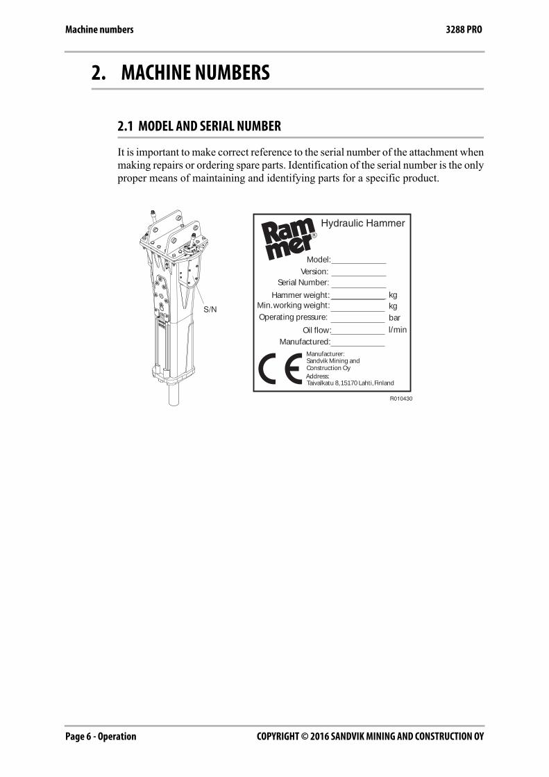
It is important to make correct reference to the serial number of the attachment whenmaking repairs or ordering spare parts. Identification of the serial number is the onlyproper means of maintaining and identifying parts for a specific product.
R010430
Hydraulic Hammer
Model:
Serial Number:
Hammer weight:Min. working weight:
Operating pressure:
Oil flow:
Manufactured:
Version:
kgkg
bar
l/min
Manufacturer:
Address:
Sandvik Mining andConstruction Oy
Taivalkatu 8, 15170 Lahti, Finland
Operation - Page 7COPYRIGHT © 2016 SANDVIK MINING AND CONSTRUCTION OY
Product introduction3288 PRO
3. PRODUCT INTRODUCTION
3.1 OVERVIEW
The product is a hydraulically operated breaker. It can be used on any carrier whichmeets the necessary hydraulic and mechanical installation requirements. The unitfunctions by repeatedly raising a steel piston and driving it down onto the head of aremovable breaking tool.
No additional pressure accumulators are necessary since the integrated pressureaccumulator absorbs hydraulic pressure peaks. The impact energy of the hammer isalmost constant and independent of the carrier's hydraulic system.
3.2 REMOVAL FROM PACKAGE
Remove all the steel belts from the package. Open the package and remove allplastics covering the product.
Recycle all package materials (steel, plastic, wood) properly.
Check that the product is in good condition and that there is no visible damage.Check that all ordered parts and accessories have been enclosed with the product.Some options may be provided by your local dealer like installation kits; includinghoses and mounting bracket.
3.3 LIFTING INSTRUCTIONS
Use a hoist when lifting components which weigh 23 kg (50 lb) or more, to avoidback injury. Make sure all lifting equipment is in good condition and are in thecorrect capacity. Be sure hooks are positioned correctly. Lifting eyes are not to beside loaded during a lifting operation. Do not use the hammer's tools for lifting.
COPYRIGHT © 2016 SANDVIK MINING AND CONSTRUCTION OYPage 8 - Operation
Product introduction 3288 PRO
PROVIDED LIFTING POINTS
Use the lifting eyes located on the product housing only to lift or handle the productitself. The lifting capacity calculation is based on the product's working weightincluding a normal working tool and an average sized mounting bracket.
Warning! To avoid falling objects, do not use the product to lift other products.Use the lifting eyes located on the product housing only to lift or handle theproduct itself.
The maximum allowed total weight is shown on the product's CE-plate andspecification page. See “Hammer specifications” on page 70. If the weight exceedsthe maximum allowed total weight shown on the CE-plate and specification page,you have to use other lifting points/methods than originally provided on the product.
The other threaded holes on the product (for example on the hammer powercell) areintended for handling single parts only. It is forbidden to lift the entire assembly byusing these threaded holes (for example on the cylinder outer surfaces). Forhandling the parts, see product workshop documentation for suitable liftingmethods and lifting adapters.
LIFTING EYE SCREWS
Tighten the lifting eye screws completely. Put a burden on the lifting eye only if thescrew is properly tightened to the housing.
Failure to properly tighten the screw before allowing load pressure on thelifting eye may cause lifting eye to break and free fall of the product.
If you use mechanical tools for tightening, make sure not to overstrain the shank.Before lifting make sure that the chain and/or hook is stretched.
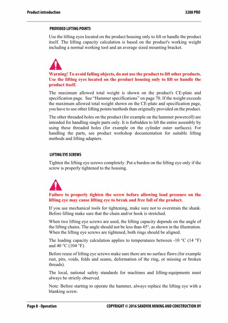
When two lifting eye screws are used, the lifting capacity depends on the angle ofthe lifting chains. The angle should not be less than 45°, as shown in the illustration.When the lifting eye screws are tightened, both rings should be aligned.
The loading capacity calculation applies to temperatures between -10 °C (14 °F)and 40 °C (104 °F).
Before reuse of lifting eye screws make sure there are no surface flaws (for examplerust, pits, voids, folds and seams, deformation of the ring, or missing or brokenthreads).
The local, national safety standards for machines and lifting-equipments mustalways be strictly observed.
Note: Before starting to operate the hammer, always replace the lifting eye with ablanking screw.
Operation - Page 9COPYRIGHT © 2016 SANDVIK MINING AND CONSTRUCTION OY
Product introduction3288 PRO
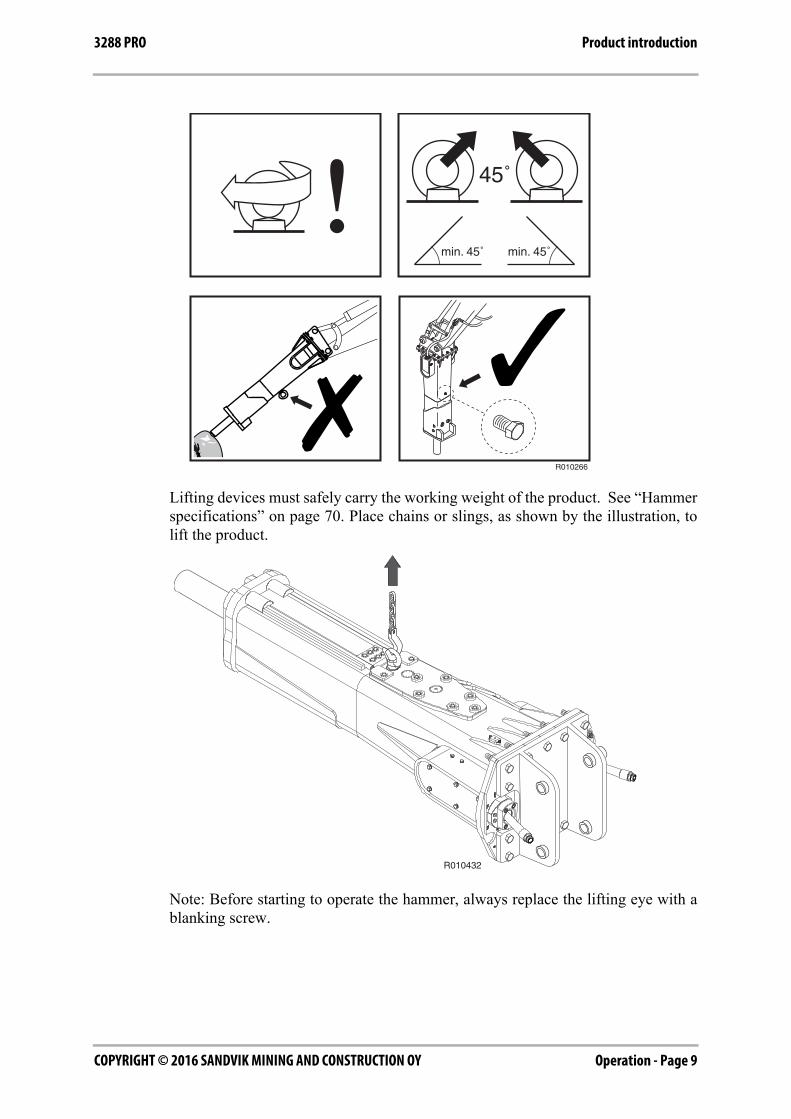
Lifting devices must safely carry the working weight of the product. See “Hammerspecifications” on page 70. Place chains or slings, as shown by the illustration, tolift the product.
Note: Before starting to operate the hammer, always replace the lifting eye with ablanking screw.
R010266
R010432
COPYRIGHT © 2016 SANDVIK MINING AND CONSTRUCTION OYPage 10 - Operation
Product introduction 3288 PRO
SAFETY INSTRUCTIONS FOR LIFTING
Below are some common safety instructions concerning lifting operations. Inaddition to this, the local, national standards for machines and lifting-equipmentsmust always be strictly observed. Please note that the list below is not all inclusive,you must always ensure the procedure you choose is safe for you and others.
■ Do not lift load over people. No one shall be under the hoisted load.
■ Do not lift people and never ride the hoisted load.
■ Keep people clear from lift area.
■ Avoid side pull of the load. Make sure you take up the slack slowly. Start andstop carefully.
■ Lift load a few centimeters and verify it before proceeding. Make sure the loadis well balanced. Check for any loose items.
■ Never leave the suspended load unattended. Maintain load control at all times.
■ Never lift the load over the rated capacity (see product's operating weight fromspecification page).
■ Inspect all lifting equipment before use. Do not use twisted or damaged liftingequipment. Protect lifting equipment from sharp corners.
■ Obey all local safety instructions.
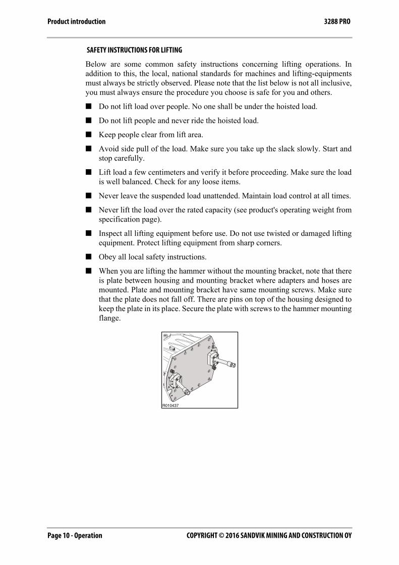
■ When you are lifting the hammer without the mounting bracket, note that thereis plate between housing and mounting bracket where adapters and hoses aremounted. Plate and mounting bracket have same mounting screws. Make surethat the plate does not fall off. There are pins on top of the housing designed tokeep the plate in its place. Secure the plate with screws to the hammer mountingflange.
R010437
Operation - Page 11COPYRIGHT © 2016 SANDVIK MINING AND CONSTRUCTION OY
Product introduction3288 PRO
3.4 MAIN PARTS
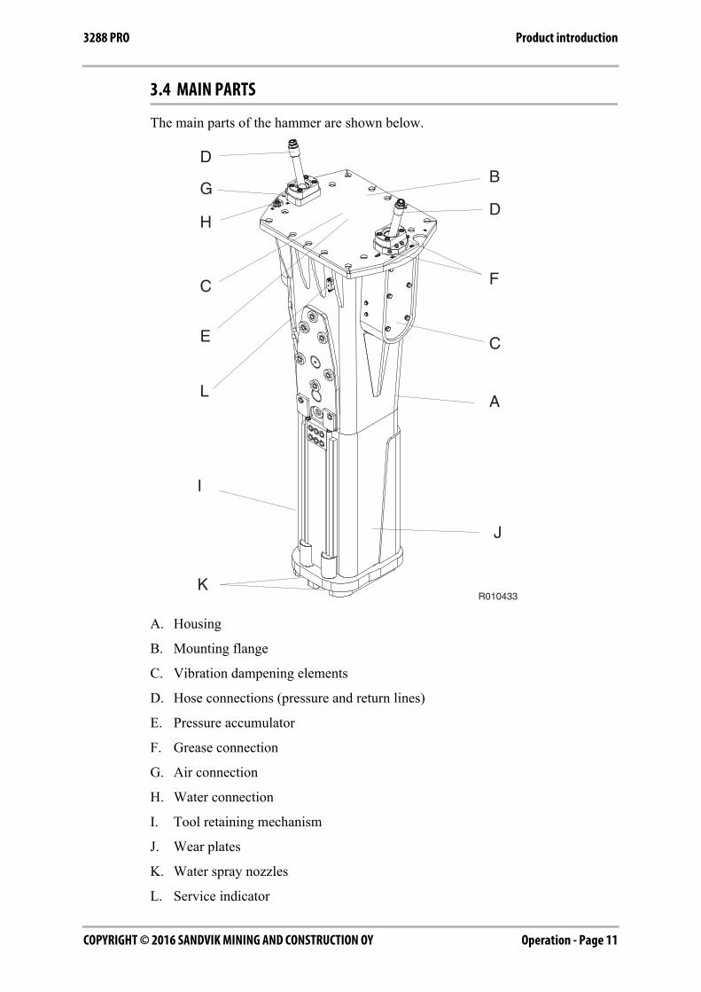
The main parts of the hammer are shown below.
A. Housing
B. Mounting flange
C. Vibration dampening elements
D. Hose connections (pressure and return lines)
E. Pressure accumulator
F. Grease connection
G. Air connection
H. Water connection
I. Tool retaining mechanism
J. Wear plates
K. Water spray nozzles
L. Service indicator
B
A
C
D
F
D
C
H
G
E
L
I
K
J
R010433
COPYRIGHT © 2016 SANDVIK MINING AND CONSTRUCTION OYPage 12 - Operation
Product introduction 3288 PRO
3.5 RAMVALVE
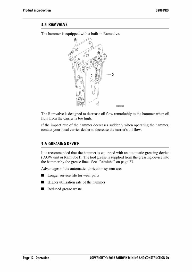
The hammer is equipped with a built-in Ramvalve.
The Ramvalve is designed to decrease oil flow remarkably to the hammer when oilflow from the carrier is too high.
If the impact rate of the hammer decreases suddenly when operating the hammer,contact your local carrier dealer to decrease the carrier's oil flow.
3.6 GREASING DEVICE
It is recommended that the hammer is equipped with an automatic greasing device( AGW unit or Ramlube I). The tool grease is supplied from the greasing device intothe hammer by the grease lines. See “Ramlube” on page 23.
Advantages of the automatic lubrication system are:
■ Longer service life for wear parts
■ Higher utilization rate of the hammer
■ Reduced grease waste
R010429
X
Operation - Page 13COPYRIGHT © 2016 SANDVIK MINING AND CONSTRUCTION OY
Product introduction3288 PRO
3.7 SERVICE INDICATOR
The Ramdata II service indicator system is designed to help the hammer operatorsand service personnel get information about the service interval status, servicehistory and accumulated working history of a hammer. See “Checking the serviceinterval status” on page 32.
POSSIBLE OPERATIONS WITH THE RAMDATA II DEVICE
■ Checking the service interval status
3.8 ENVIRONMENTAL PROTECTION AND RECYCLING POLICY
Rammer products contribute to the recycling of materials to help customers achievetheir environmental objectives. During the manufacturing, all the necessaryprecautions are taken to make sure that no harm is done to the environment.
Every effort is made to foresee and minimize the risks that might be associated withthe operation and maintenance of Rammer products, and which could pose dangerto humans or the environment. We support customers in their efforts to consider theenvironmental protection in their everyday work.
When working with a Rammer product please follow these guidelines:
■ Dispose of packaging materials properly. Wood and plastic can be burned orrecycled. Deliver the steel belts to metal recycling center.
■ Protect environment from oil spills.
In case of hydraulic oil leaks, the equipment should be serviced immediately.
Follow the product's greasing instructions and avoid excessive greasing.
Be careful when handling, storing and transporting oils.
Dispose of empty oil or grease containers appropriately.
Consult local authorities for detailed instructions.
■ All metal parts of the product can be recycled by delivering them to anauthorized scrap metal collection facility.
■ Comply with local waste classification rules when disposing of used rubber orplastic parts (buffers, wear plates, seals).
■ When scrapping the whole product or pressure accumulator, consult your localRammer dealer for instructions on depressurizing the accumulator.
■ Do not bring the product or accumulator to a scrap metal collection centerbefore depressurizing the accumulator first.
Consult with your local dealer for more information.

COPYRIGHT © 2016 SANDVIK MINING AND CONSTRUCTION OYPage 14 - Operation
Safety 3288 PRO
4. SAFETY
4.1 GENERAL SAFETY
All mechanical equipment can be hazardous if operated without due care or correctmaintenance. Most accidents involving machine operation and maintenance arecaused by failure to observe basic safety rules or precautions. An accident can oftenbe avoided by recognizing potentially hazardous situations before an accidentoccurs.
Warning! Read the following warning messages carefully. They tell you ofdifferent hazards and how to avoid them. If proper precautions are not takenyou or others could be seriously injured.
4.2 SAFETY INSTRUCTIONS
MANUALS
Study this manual before installing, operating or maintaining the product. If there isanything you don't understand, ask your employer or your local dealer to explain it.Keep this manual clean and in good condition.
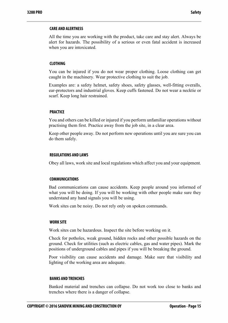
The related safety label on the hammer and the text on the label are shown below.
"IGNORING INSTRUCTIONS HAZARD
Faulty handling practice could cause death or serious injury.
Read and follow the instructions in the operator's manual."
R010354
IGNORINGINSTRUCTIONS HAZARDFaulty handling practice couldcause death or severe injury.Read and follow theinstructions in the operator’smanual.
WARNING
169400_ENG-3
Operation - Page 15COPYRIGHT © 2016 SANDVIK MINING AND CONSTRUCTION OY
Safety3288 PRO
CARE AND ALERTNESS
All the time you are working with the product, take care and stay alert. Always bealert for hazards. The possibility of a serious or even fatal accident is increasedwhen you are intoxicated.
CLOTHING
You can be injured if you do not wear proper clothing. Loose clothing can getcaught in the machinery. Wear protective clothing to suit the job.
Examples are: a safety helmet, safety shoes, safety glasses, well-fitting overalls,ear-protectors and industrial gloves. Keep cuffs fastened. Do not wear a necktie orscarf. Keep long hair restrained.
PRACTICE
You and others can be killed or injured if you perform unfamiliar operations withoutpractising them first. Practice away from the job site, in a clear area.
Keep other people away. Do not perform new operations until you are sure you cando them safely.
REGULATIONS AND LAWS
Obey all laws, work site and local regulations which affect you and your equipment.
COMMUNICATIONS
Bad communications can cause accidents. Keep people around you informed ofwhat you will be doing. If you will be working with other people make sure theyunderstand any hand signals you will be using.
Work sites can be noisy. Do not rely only on spoken commands.
WORK SITE
Work sites can be hazardous. Inspect the site before working on it.
Check for potholes, weak ground, hidden rocks and other possible hazards on theground. Check for utilities (such as electric cables, gas and water pipes). Mark thepositions of underground cables and pipes if you will be breaking the ground.
Poor visibility can cause accidents and damage. Make sure that visibility andlighting of the working area are adequate.
BANKS AND TRENCHES
Banked material and trenches can collapse. Do not work too close to banks andtrenches where there is a danger of collapse.
COPYRIGHT © 2016 SANDVIK MINING AND CONSTRUCTION OYPage 16 - Operation
Safety 3288 PRO
SAFETY BARRIERS
Unguarded equipment in public places can be dangerous. Place barriers around themachine to keep people away.
AIRBORNE POLLUTANTS
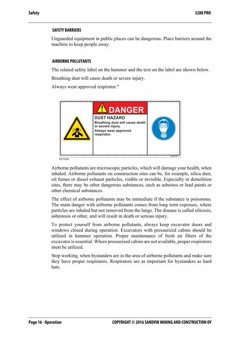
The related safety label on the hammer and the text on the label are shown below.
Breathing dust will cause death or severe injury.
Always wear approved respirator."
Airborne pollutants are microscopic particles, which will damage your health, wheninhaled. Airborne pollutants on construction sites can be, for example, silica dust,oil fumes or diesel exhaust particles, visible or invisible. Especially in demolitionsites, there may be other dangerous substances, such as asbestos or lead paints orother chemical substances.
The effect of airborne pollutants may be immediate if the substance is poisonous.The main danger with airborne pollutants comes from long term exposure, whereparticles are inhaled but not removed from the lungs. The disease is called silicosis,asbestosis or other, and will result in death or serious injury.
To protect yourself from airborne pollutants, always keep excavator doors andwindows closed during operation. Excavators with pressurized cabins should beutilized in hammer operation. Proper maintenance of fresh air filters of theexcavator is essential. Where pressurized cabins are not available, proper respiratorsmust be utilized.
Stop working, when bystanders are in the area of airborne pollutants and make surethey have proper respirators. Respirators are as important for bystanders as hardhats.
R010356
DUST HAZARDBreathing dust will cause deathor severe injury.Always wear approvedrespirator.
DANGER
169400_ENG-1
Operation - Page 17COPYRIGHT © 2016 SANDVIK MINING AND CONSTRUCTION OY
Safety3288 PRO
Respirators for both operator and bystanders must be approved by the respiratormanufacturer for the application in question. It is essential that the respiratorsprotect from the tiny dust particles which cause silicosis and which may cause otherserious lung diseases. You should not use the equipment until you are sure therespirators are working properly. This means the respirators must be checked tomake sure that it is clean, that its filter has been changed, and to otherwise make surethe respirator will protect in the way it is meant to.
Always make sure dust has been cleaned off your boots and clothes when you leaveyour shift. The smallest particles of dust are the most harmful. They may be so finethat you can not see them. Remember, you MUST protect yourself and bystandersfrom the danger of breathing or inhaling dust.
Always follow local laws and regulations for airborne pollutants in the workingenvironment.
FLYING CHIPS OF ROCK
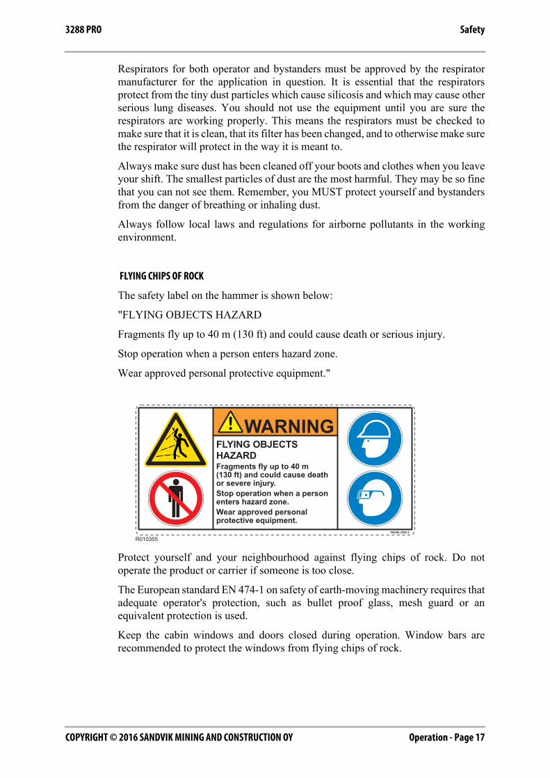
The safety label on the hammer is shown below:
"FLYING OBJECTS HAZARD
Fragments fly up to 40 m (130 ft) and could cause death or serious injury.
Stop operation when a person enters hazard zone.
Wear approved personal protective equipment."
Protect yourself and your neighbourhood against flying chips of rock. Do notoperate the product or carrier if someone is too close.
The European standard EN 474-1 on safety of earth-moving machinery requires thatadequate operator's protection, such as bullet proof glass, mesh guard or anequivalent protection is used.
Keep the cabin windows and doors closed during operation. Window bars arerecommended to protect the windows from flying chips of rock.
R010355
FLYING OBJECTSHAZARDFragments fly up to 40 m(130 ft) and could cause deathor severe injury.Stop operation when a personenters hazard zone.Wear approved personalprotective equipment.
WARNING
169400_ENG-2
COPYRIGHT © 2016 SANDVIK MINING AND CONSTRUCTION OYPage 18 - Operation
Safety 3288 PRO
HIGH NOISE LEVEL
A hammer in operation creates a high noise level. Always wear ear protection toprevent personal injury.
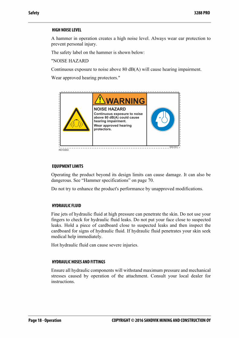
The safety label on the hammer is shown below:
"NOISE HAZARD
Continuous exposure to noise above 80 dB(A) will cause hearing impairment.
Wear approved hearing protectors."
EQUIPMENT LIMITS
Operating the product beyond its design limits can cause damage. It can also bedangerous. See “Hammer specifications” on page 70.
Do not try to enhance the product's performance by unapproved modifications.
HYDRAULIC FLUID
Fine jets of hydraulic fluid at high pressure can penetrate the skin. Do not use yourfingers to check for hydraulic fluid leaks. Do not put your face close to suspectedleaks. Hold a piece of cardboard close to suspected leaks and then inspect thecardboard for signs of hydraulic fluid. If hydraulic fluid penetrates your skin seekmedical help immediately.
Hot hydraulic fluid can cause severe injuries.
HYDRAULIC HOSES AND FITTINGS
Ensure all hydraulic components will withstand maximum pressure and mechanicalstresses caused by operation of the attachment. Consult your local dealer forinstructions.
R010353
NOISE HAZARDContinuous exposure to noiseabove 80 dB(A) could causehearing impairment.Wear approved hearingprotectors.
WARNING
169400_ENG-4
Operation - Page 19COPYRIGHT © 2016 SANDVIK MINING AND CONSTRUCTION OY
Safety3288 PRO
FIRE HAZARD
Most hydraulic fluids are flammable and might ignite when contacting hot surface.Avoid spilling hydraulic fluid to hot surfaces.
Working with the product on certain materials can cause sparks and hot splinters toget loose. These can ignite flammable materials around working area.
Ensure that adequate extinguisher is available.
HYDRAULIC PRESSURE
Hydraulic fluid at system pressure can injure you. Before disconnecting orconnecting hydraulic hoses, stop the carrier engine, operate the controls to releasepressure trapped in the hoses and wait ten (10) minutes. During the operation, keeppeople away from the hydraulic hoses.
There might be pressurized oil trapped inside the product even if it is disconnectedfrom the carrier. Be aware of possible blank firing while greasing or removing andinstalling hammer tools. See “Changing the tool” on page 56.
PRESSURE ACCUMULATORS
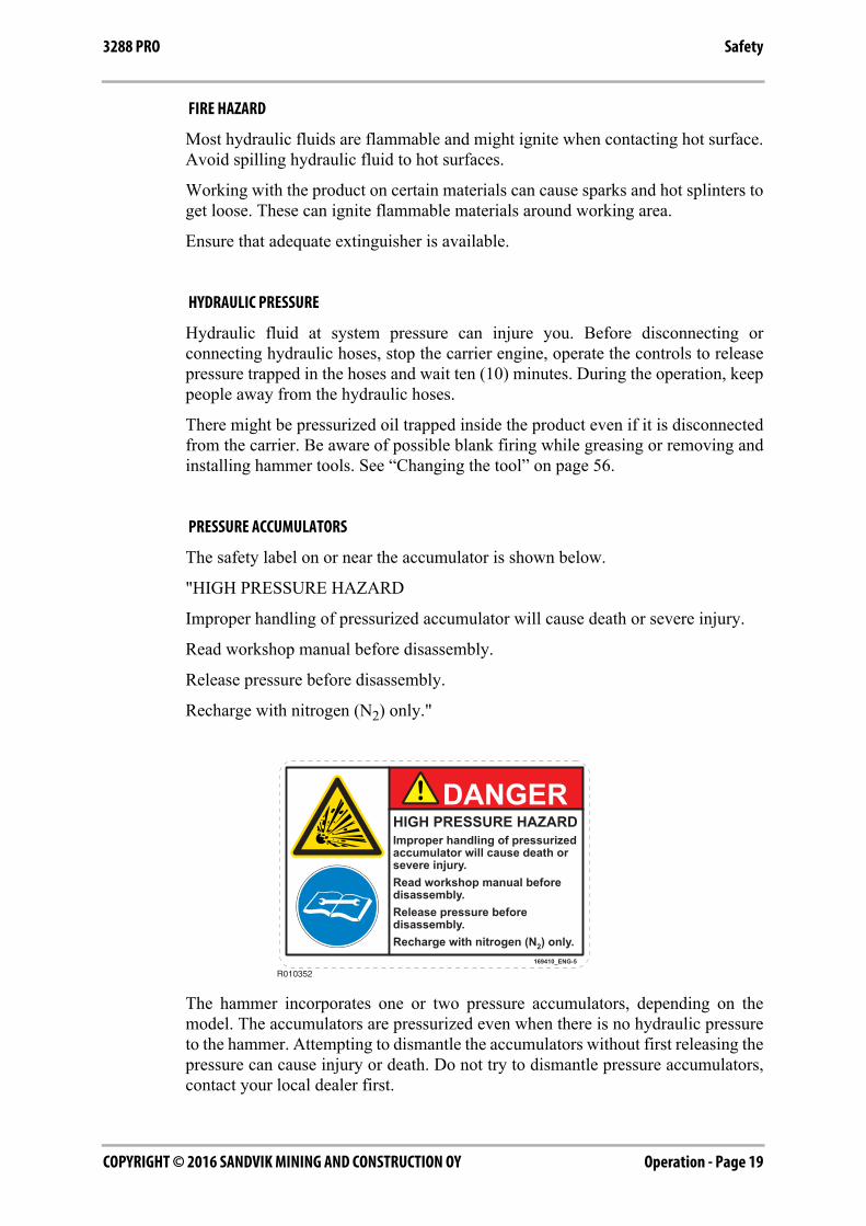
The safety label on or near the accumulator is shown below.
"HIGH PRESSURE HAZARD
Improper handling of pressurized accumulator will cause death or severe injury.
Read workshop manual before disassembly.
Release pressure before disassembly.
Recharge with nitrogen (N2) only."
The hammer incorporates one or two pressure accumulators, depending on themodel. The accumulators are pressurized even when there is no hydraulic pressureto the hammer. Attempting to dismantle the accumulators without first releasing thepressure can cause injury or death. Do not try to dismantle pressure accumulators,contact your local dealer first.
R010352
DANGERHIGH PRESSURE HAZARDImproper handling of pressurizedaccumulator will cause death or severe injury.Read workshop manual beforedisassembly.Release pressure beforedisassembly.Recharge with nitrogen (N2) only.
169410_ENG-5
COPYRIGHT © 2016 SANDVIK MINING AND CONSTRUCTION OYPage 20 - Operation
Safety 3288 PRO
LIFTING EQUIPMENT
You can be injured if you use faulty lifting equipment. Make sure that liftingequipment is in good condition. Make sure that the lifting equipment complies withall local regulations and is suitable for the job. Make sure that the lifting equipmentis strong enough for the job and that you know how to use it.
Do not use this product or any of its parts for lifting. See “Lifting instructions” onpage 7. Contact your carrier dealer to find out how to lift with your carrier.
SPARE PARTS
Use only genuine spare parts. Use only genuine tools with hydraulic hammers. Theuse of other spare part or hammer tool brands may damage the product.
EQUIPMENT CONDITION
Defective equipment can injure you or others. Do not operate equipment which isdefective or has missing parts.
Make sure the maintenance procedures in this manual are completed before usingthe product.
REPAIRS AND MAINTENANCE
Do not try to do repairs or any other maintenance work you do not understand.
MODIFICATIONS AND WELDING
Non-approved modifications can cause injury and damage. Contact your localdealer for advice before modifying the product. Before welding on the productwhile it is installed on the carrier, disconnect the carrier alternator and battery. Notethat welding of the hammer tools will render them useless and make the warrantyvoid.
METAL SPLINTERS
You can be injured by flying splinters when driving metal pins in and out. Use soft-faced hammer or drifts to remove and fit metal pins, such as pivot pins. Always wearsafety glasses.
Operation - Page 21COPYRIGHT © 2016 SANDVIK MINING AND CONSTRUCTION OY
Safety3288 PRO
LABELS ON THE PRODUCT
Safety labels communicate the following four things:
■ The severity level of the risk (that is, signal word "DANGER" or"WARNING").
■ The nature of the hazard (such as high pressure, or dust).
■ The consequence of interaction with the hazard.
■ How to avoid the hazard.
You must ALWAYS follow the instructions of the safety messages and symbols ofthe product safety labels and the instructions set forth in the manuals to avoid deathor severe injury!
Keep the safety labels clean and visible at all times. Check the condition of safetylabels daily. Safety labels and instructions which have disappeared, been damaged,painted over, come loose or do not meet the legibility requirements for safe viewingdistance, must be replaced before operating the product.
If a safety label is attached to a part that is replaced, install a new safety label on thereplacement part. If this manual is available in your language, then the safety labelsshould be available in the same language.
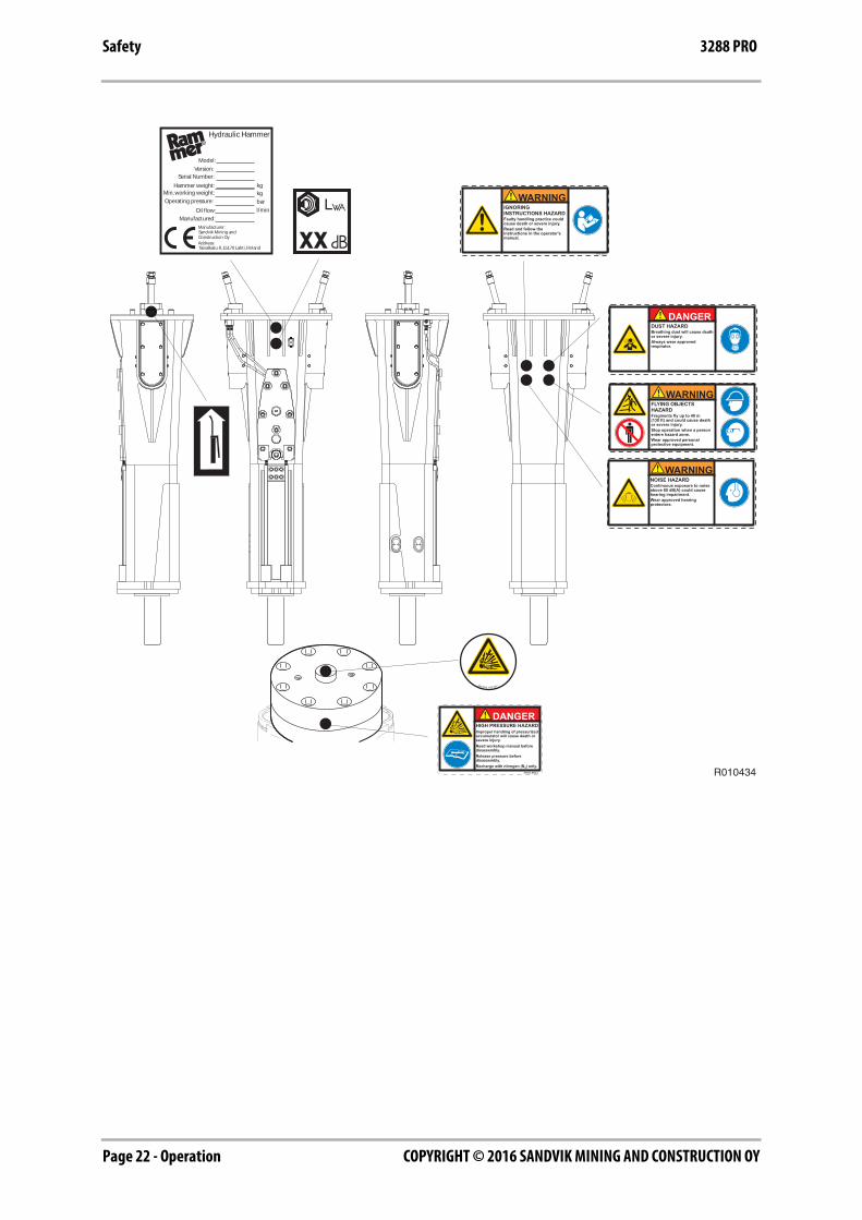
There are several specific safety labels on this hammer. Please become familiarizedwith all safety labels. The location of the safety labels is shown in the illustrationbelow.
When you clean the safety labels, use a cloth, water and soap. Do not use solvent,gasoline or other harsh chemicals to clean the safety labels.
Solvents, gasoline or harsh chemicals could loosen the adhesive that secures thesafety labels. Loose adhesive will allow the safety label to fall.
COPYRIGHT © 2016 SANDVIK MINING AND CONSTRUCTION OYPage 22 - Operation
Safety 3288 PRO
R010434
Sandvik 168 907
DANGERHIGH PRESSURE HAZARDImproper handling of pressurizedaccumulator will cause death or severe injury.Read workshop manual beforedisassembly.Release pressure beforedisassembly.Recharge with nitrogen (N2) only.
169410_ENG-5
IGNORINGINSTRUCTIONS HAZARDFaulty handling practice couldcause death or severe injury.Read and follow theinstructions in the operator'smanual.
WARNING
169400_ENG-3
FLYING OBJECTSHAZARDFragments fly up to 40 m(130 ft) and could cause deathor severe injury.Stop operation when a personenters hazard zone.Wear approved personalprotective equipment.
WARNING
169400_ENG-2
NOISE HAZARDContinuous exposure to noiseabove 80 dB(A) could causehearing impairment.Wear approved hearingprotectors.
WARNING
169400_ENG-4
DUST HAZARDBreathing dust will cause deathor severe injury.Always wear approvedrespirator.
DANGER
169400_ENG-1
Hydraulic Hammer
Model:
Serial Number:
Hammer weight:Min. working weight:
Operating pressure:
Oil flow:
Manufactured:
Version:
kgkg
bar
l/min
Manufacturer:
Address:
Sandvik Mining andConstruction Oy
Taivalkatu 8, 15170 Lahti, Finland
Operation - Page 23COPYRIGHT © 2016 SANDVIK MINING AND CONSTRUCTION OY
Optional equipment3288 PRO
5. OPTIONAL EQUIPMENT
5.1 AGW UNIT
AGW (Air, Grease & Water) service unit contains an automatic greasing device, airflush system and water spray system. AGW supplies the hammer with tool grease,compressed air and water via hoses. It is mounted outside the carrier cabin.
Advantages of the AGW system are:
■ Longer service life for wear parts
■ Higher utilization rate of the hammer
■ Grease waste reduced
■ Added dust protection prevents dirt from entering the hammer's tool chamberand reduces dust during breaking
5.2 RAMLUBE
Lubrication of the tool and the tool bushings of the hammer can be madeautomatically by equipping the carrier with a lubrication pump. The tool grease issupplied from the pump into the hammer by hose. During operation, grease holdermust be filled with suitable tool grease. Adjust pump output to working conditions.
Advantages of the automatic lubrication system are:
■ Longer service life for wear parts
■ Higher utilization rate of the hammer
■ Grease waste reduced
The latest hammer models are equipped with a automatic lubrication systemconnection point, from where the tool grease is fed along an internal channel to thetool bushing and the tool shank.
COPYRIGHT © 2016 SANDVIK MINING AND CONSTRUCTION OYPage 24 - Operation
Optional equipment 3288 PRO
5.3 RAMAIR II
The Ramair air flush system is designed to prevent dirt from entering the hammer'stool chamber and keep the tool grease flowing towards the lower tool bushing. Theair flush system is most beneficial in applications where the material is highlyabrasive and dusty. Also in the applications where the hammer working position ishorizontal or above, such as tunneling and scaling applications.
The Ramair air flush system consists of hydraulically driven air compressor fittedon the carrier, hoses for the hydraulics and compressed air, and inbuilt channel inthe hammer's power cell. The air compressor is powered by the hammer supplycircuit and is activated during the hammer operation.
Important notes:
■ Only the air compressor can be obtained from Sandvik. Hoses and otherinstallation components must be sourced locally.
■ The Ramair air flush system is not applicable to underwater hammerwork.
■ Ramair air compressor must be installed so, that carrier maintenance andmoving to cabin is easy. Installation of compressor have to be firm.
5.4 WATER JET
Warning! Protect yourself and your surroundings against pressurized waterspray. Do not operate the hammer or carrier if someone is too close to thehammer.
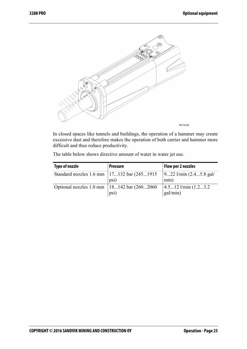
This product is equipped with an integrated water spray system in the hammerhousing. The water supply is connected to the hammer by using R1/2" connectorsin the housing. The internal tubes lead under the bottom plate and the water issprayed through the nozzles onto the object to be broken and the tool.
The principle behind the water spray system is to decrease the amount of dustcaused by the breaking operation. The water jet reduces the amount of dusteffectively. The use of this system is especially recommended for tunneling anddemolition applications.
Operation - Page 25COPYRIGHT © 2016 SANDVIK MINING AND CONSTRUCTION OY
Optional equipment3288 PRO
In closed spaces like tunnels and buildings, the operation of a hammer may createexcessive dust and therefore makes the operation of both carrier and hammer moredifficult and thus reduce productivity.
The table below shows directive amount of water in water jet use.
Type of nozzle Pressure Flow per 2 nozzles
Standard nozzles 1.6 mm 17...132 bar (245...1915 psi)
9...22 l/min (2.4...5.8 gal/min)
Optional nozzles 1.0 mm 18...142 bar (260...2060 psi)
4.5...12 l/min (1.2...3.2 gal/min)
R010436
COPYRIGHT © 2016 SANDVIK MINING AND CONSTRUCTION OYPage 26 - Operation
Operation 3288 PRO
6. OPERATION
6.1 OPERATING INSTRUCTIONS
RECOMMENDED USE
The hammer is designed to be used in primary breaking, tunnelling, trenching andhorizontal breaking. Your local dealer will gladly give you more information.
OPERATING CONDITIONS
Principle of installation
Almost all carriers meeting mechanical and hydraulic requirements can be used tooperate the attachment. See “Hammer specifications” on page 70. The product isinstalled on the carrier much in the same manner as installing a bucket or otherattachments. A flange mounted attachment requires a separate mounting bracket.
If the carrier has already auxiliary hydraulic circuit, the installation requires onlysuitable hoses and fittings. If the carrier does not have suitable kit to run theattachment, one must be built. This may require installation including new pipingand additional valves such as directional valve and pressure relief valve.
Suitable kits can be ordered from the local dealers, from carrier manufacturers andtheir dealers or from third party suppliers.
Hydraulic oil
In general the hydraulic oil originally intended for the carrier can be used with thisproduct. See “Requirements for hydraulic oil” on page 46.
Operating temperature
The operating temperature is -20 °C (-4 °F) to 80 °C (176 °F). If the temperature islower than -20 °C (-4 °F), the hammer and tool have to be preheated before anyoperations can begin, in order to avoid breaking the accumulator's membrane andthe tool. During operation they will remain warm. See “Preheating the hammer” onpage 30.
Note: The temperature of the hydraulic oil must be monitored. Ensure that oil gradeand monitored oil temperature together guarantee correct oil viscosity. See “Oilspecifications” on page 47.

Operation - Page 27COPYRIGHT © 2016 SANDVIK MINING AND CONSTRUCTION OY
Operation3288 PRO
Noise dampening
Operating the hammer near residential areas or other noise sensitive areas can causenoise pollution. In order to avoid unnecessary noise, please follow these basic rules:
1. When operating with the hammer, keep the tool at 90 degree angle to thematerial and the feed force in-line with the tool.
2. Replace or fix all parts that are worn out, damaged or loosened. This not onlysaves your hammer but it also decreases the noise level.
PRINCIPLES OF BREAKING
To increase the hammer's working life, pay particular attention to correct workingmethods and how to choose the correct tool for the job. There are essentially twoways of breaking with a hydraulic hammer.
CHOOSING TOOLS
It is recommended to use Z-series tool for PRO-models hammer. Z-series tools aredesigned for tunnelling, primary breaking and horizontal working. A selection ofstandard and special tools to suit each application are available. The correct type oftool must be selected to get the best possible working results and longest life timefor the tool. Choosing the best tool type for an application may require some testing,please consult with your local dealer. See “Tool specifications” on page 72.
Chisel and moil point
■ For sedimentary (e.g. sandstone) and weak metamorphic rock into which thetool penetrates.
■ Concrete.
■ Trenching and benching.
Limestone chisel
■ Very soft and easily breaking, non-abrasive rock or concrete.
■ For rock which has high penetration rate.
Hard rock chisel
■ Hard and abrasive rock with fractures.
■ For application where drilling and blasting cannot be used.
■ Materials with low penetration rate.
It is important to choose a tool, which is suitable for your hammer and for theapplication you are working on. The tool selection available depend on hammermodel. For more information consult with your local dealer. See “Toolspecifications” on page 72.
COPYRIGHT © 2016 SANDVIK MINING AND CONSTRUCTION OYPage 28 - Operation
Operation 3288 PRO
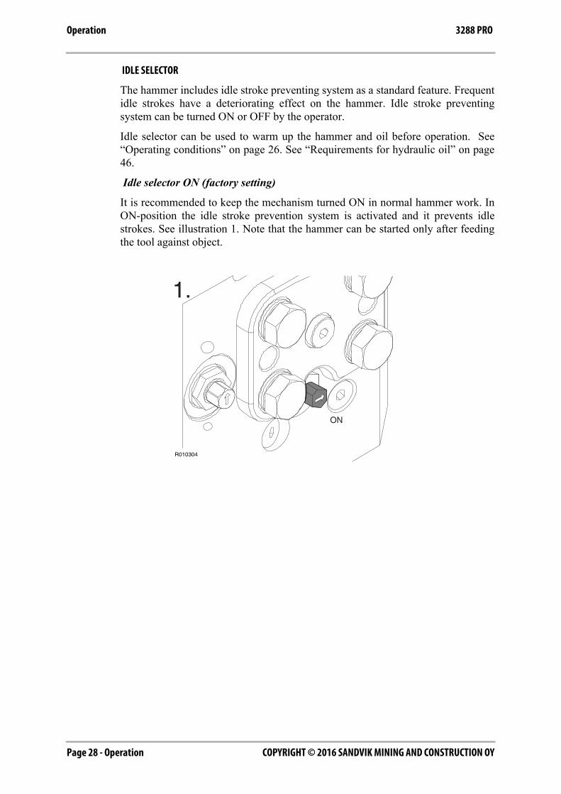
IDLE SELECTOR
The hammer includes idle stroke preventing system as a standard feature. Frequentidle strokes have a deteriorating effect on the hammer. Idle stroke preventingsystem can be turned ON or OFF by the operator.
Idle selector can be used to warm up the hammer and oil before operation. See“Operating conditions” on page 26. See “Requirements for hydraulic oil” on page46.
Idle selector ON (factory setting)
It is recommended to keep the mechanism turned ON in normal hammer work. InON-position the idle stroke prevention system is activated and it prevents idlestrokes. See illustration 1. Note that the hammer can be started only after feedingthe tool against object.
ON
R010304
1.

Operation - Page 29COPYRIGHT © 2016 SANDVIK MINING AND CONSTRUCTION OY
Operation3288 PRO
Idle selector OFF
Idle selector can be turned OFF when breaking very soft material or in demolitionapplication where it is difficult to apply enough feeding force. See illustration 2.
TURNING IDLE SELECTOR ON AND OFF
1. Remove cover.
2. Turn the screw clockwise (to ON-position) or counter-clockwise (to OFF-position) as shown in illustration below.
3. Insert cover. Tightening torque for cover mounting screws is 175 Nm.
Note: Idle selector has only two positions, ON and OFF. Do not apply any otherpositions in between.
OFF
R010305
2.
ON
OFF
R010438
COPYRIGHT © 2016 SANDVIK MINING AND CONSTRUCTION OYPage 30 - Operation
Operation 3288 PRO
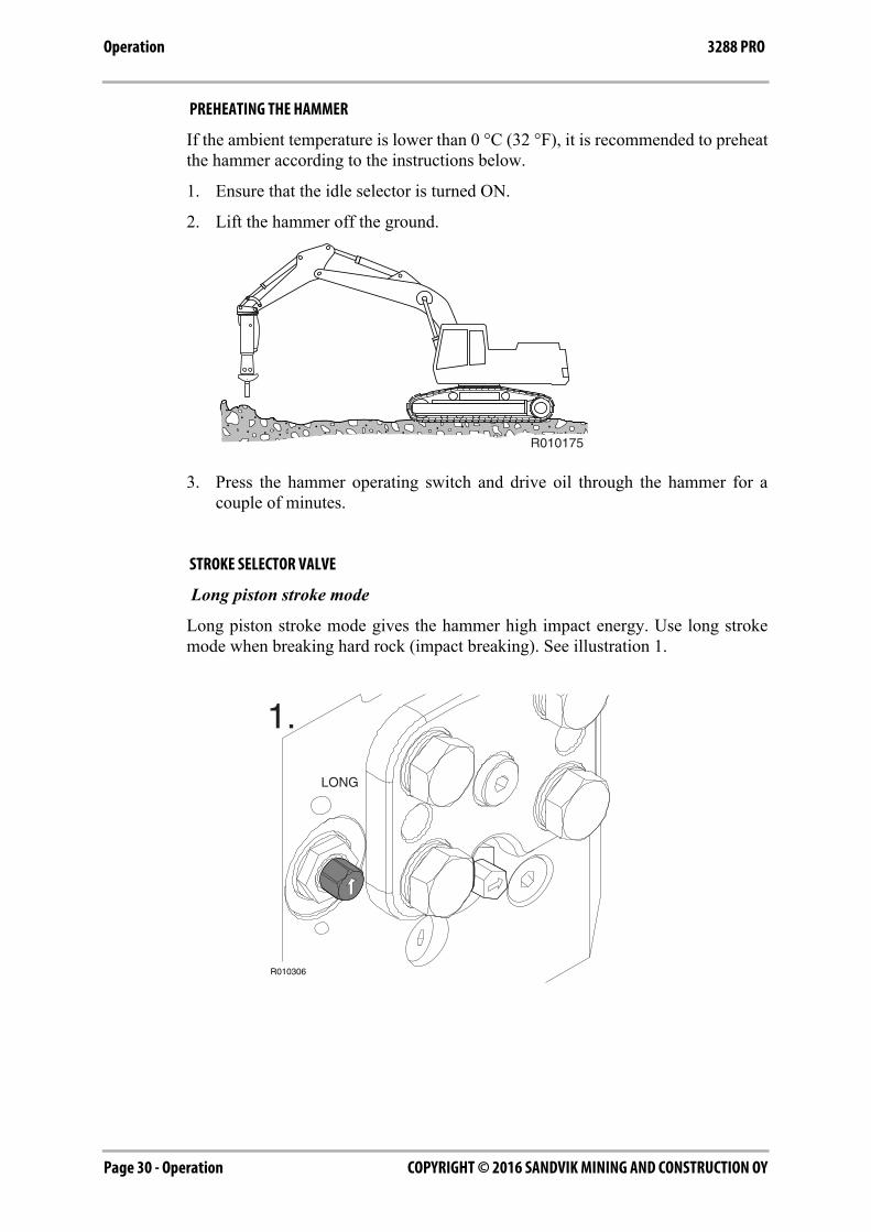
PREHEATING THE HAMMER
If the ambient temperature is lower than 0 °C (32 °F), it is recommended to preheatthe hammer according to the instructions below.
1. Ensure that the idle selector is turned ON.
2. Lift the hammer off the ground.
3. Press the hammer operating switch and drive oil through the hammer for acouple of minutes.
STROKE SELECTOR VALVE
Long piston stroke mode
Long piston stroke mode gives the hammer high impact energy. Use long strokemode when breaking hard rock (impact breaking). See illustration 1.
R010175
LONG
R010306
1.

Operation - Page 31COPYRIGHT © 2016 SANDVIK MINING AND CONSTRUCTION OY
Operation3288 PRO
Short piston stroke mode (factory setting)
Short piston stroke mode gives the hammer high impact rate. Use short stroke modewhen breaking concrete or soft rock (penetrative breaking). See illustration 2.
Note: Stroke selector has only two positions, long and short piston stroke mode. Donot apply any other positions in between.
SELECTING LONG AND SHORT STROKE MODE
1. Remove cover.
2. Turn the screw clockwise (to short stroke mode) or counter-clockwise (to longstroke mode) as shown in illustration below.
3. Insert cover. Tightening torque for cover mounting screws is 175 Nm.
Note: Stroke selector has only two positions, short stroke and long stroke. Do notapply any other positions in between.
SHORT
R010307
2.
R010439
SHORT
LONG
COPYRIGHT © 2016 SANDVIK MINING AND CONSTRUCTION OYPage 32 - Operation
Operation 3288 PRO
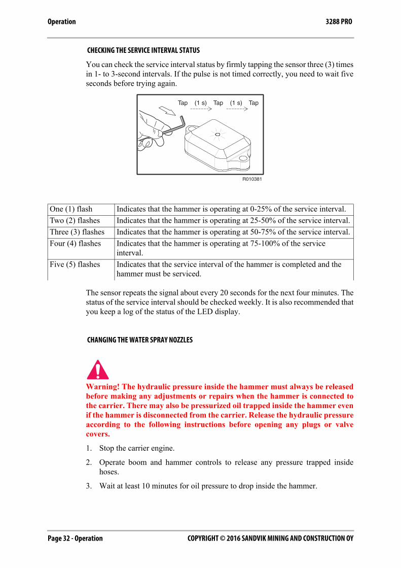
CHECKING THE SERVICE INTERVAL STATUS
You can check the service interval status by firmly tapping the sensor three (3) timesin 1- to 3-second intervals. If the pulse is not timed correctly, you need to wait fiveseconds before trying again.
The sensor repeats the signal about every 20 seconds for the next four minutes. Thestatus of the service interval should be checked weekly. It is also recommended thatyou keep a log of the status of the LED display.
CHANGING THE WATER SPRAY NOZZLES
Warning! The hydraulic pressure inside the hammer must always be releasedbefore making any adjustments or repairs when the hammer is connected tothe carrier. There may also be pressurized oil trapped inside the hammer evenif the hammer is disconnected from the carrier. Release the hydraulic pressureaccording to the following instructions before opening any plugs or valvecovers.
1. Stop the carrier engine.
2. Operate boom and hammer controls to release any pressure trapped insidehoses.
3. Wait at least 10 minutes for oil pressure to drop inside the hammer.
One (1) flash Indicates that the hammer is operating at 0-25% of the service interval.
Two (2) flashes Indicates that the hammer is operating at 25-50% of the service interval.
Three (3) flashes Indicates that the hammer is operating at 50-75% of the service interval.
Four (4) flashes Indicates that the hammer is operating at 75-100% of the service interval.
Five (5) flashes Indicates that the service interval of the hammer is completed and the hammer must be serviced.
Tap (1 s) Tap (1 s) Tap
R010381
Operation - Page 33COPYRIGHT © 2016 SANDVIK MINING AND CONSTRUCTION OY
Operation3288 PRO
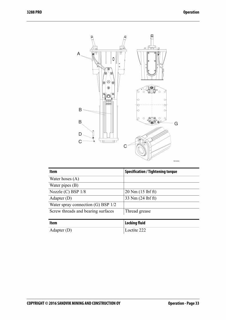
Item Specification / Tightening torque
Water hoses (A)
Water pipes (B)
Nozzle (C) BSP 1/8 20 Nm (15 lbf ft)
Adapter (D) 33 Nm (24 lbf ft)
Water spray connection (G) BSP 1/2
Screw threads and bearing surfaces Thread grease
Item Locking fluid
Adapter (D) Loctite 222
R010455
A
G
C
B
B
D
C
COPYRIGHT © 2016 SANDVIK MINING AND CONSTRUCTION OYPage 34 - Operation
Operation 3288 PRO
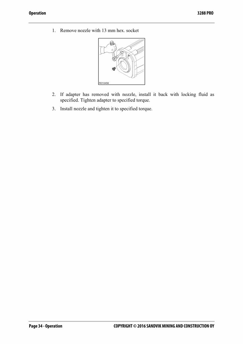
1. Remove nozzle with 13 mm hex. socket
2. If adapter has removed with nozzle, install it back with locking fluid asspecified. Tighten adapter to specified torque.
3. Install nozzle and tighten it to specified torque.
R010456
Operation - Page 35COPYRIGHT © 2016 SANDVIK MINING AND CONSTRUCTION OY
Operation3288 PRO
6.2 DAILY OPERATION
GENERAL GUIDELINES
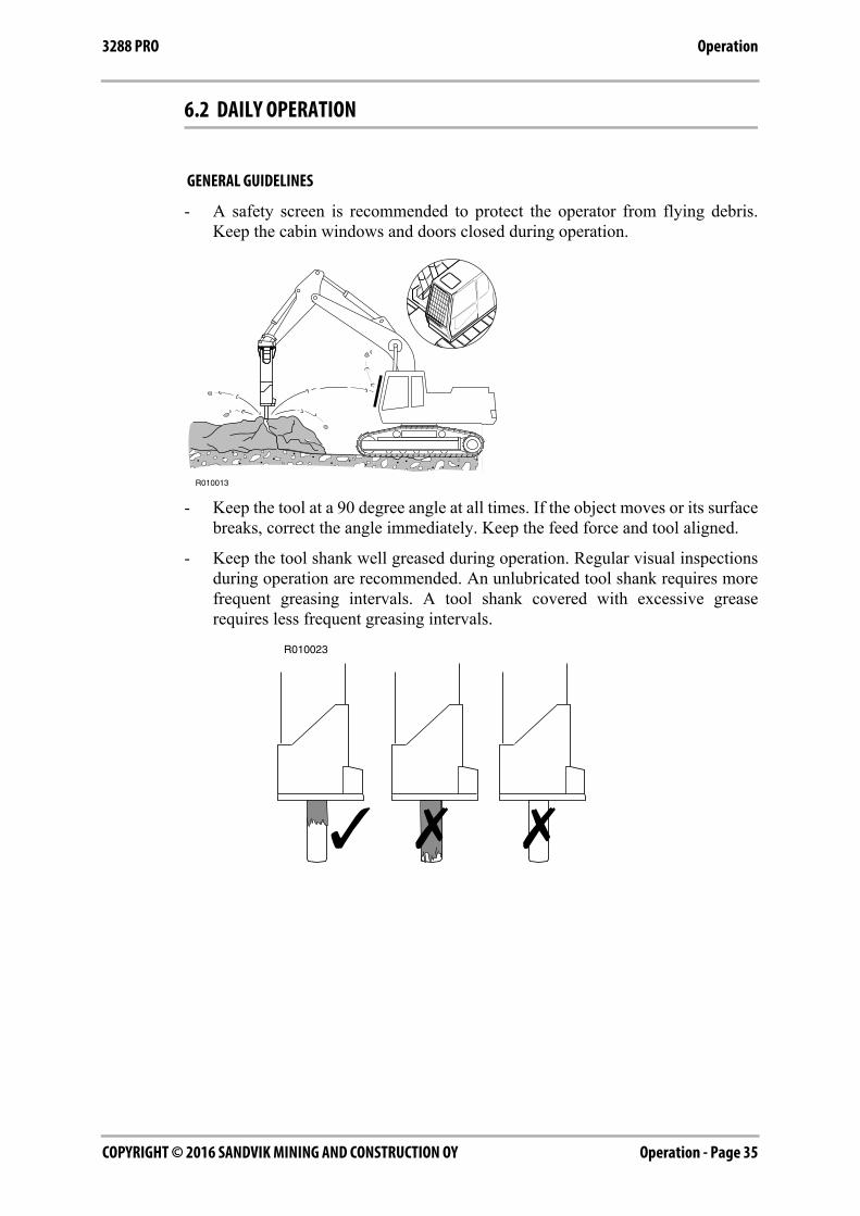
- A safety screen is recommended to protect the operator from flying debris.Keep the cabin windows and doors closed during operation.
- Keep the tool at a 90 degree angle at all times. If the object moves or its surfacebreaks, correct the angle immediately. Keep the feed force and tool aligned.
- Keep the tool shank well greased during operation. Regular visual inspectionsduring operation are recommended. An unlubricated tool shank requires morefrequent greasing intervals. A tool shank covered with excessive greaserequires less frequent greasing intervals.
COPYRIGHT © 2016 SANDVIK MINING AND CONSTRUCTION OYPage 36 - Operation
Operation 3288 PRO
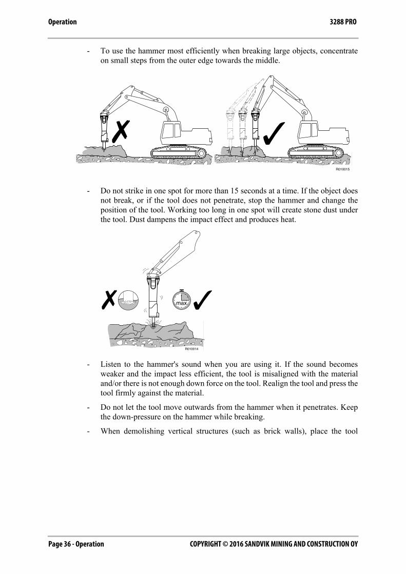
- To use the hammer most efficiently when breaking large objects, concentrateon small steps from the outer edge towards the middle.
- Do not strike in one spot for more than 15 seconds at a time. If the object doesnot break, or if the tool does not penetrate, stop the hammer and change theposition of the tool. Working too long in one spot will create stone dust underthe tool. Dust dampens the impact effect and produces heat.
- Listen to the hammer's sound when you are using it. If the sound becomesweaker and the impact less efficient, the tool is misaligned with the materialand/or there is not enough down force on the tool. Realign the tool and press thetool firmly against the material.
- Do not let the tool move outwards from the hammer when it penetrates. Keepthe down-pressure on the hammer while breaking.
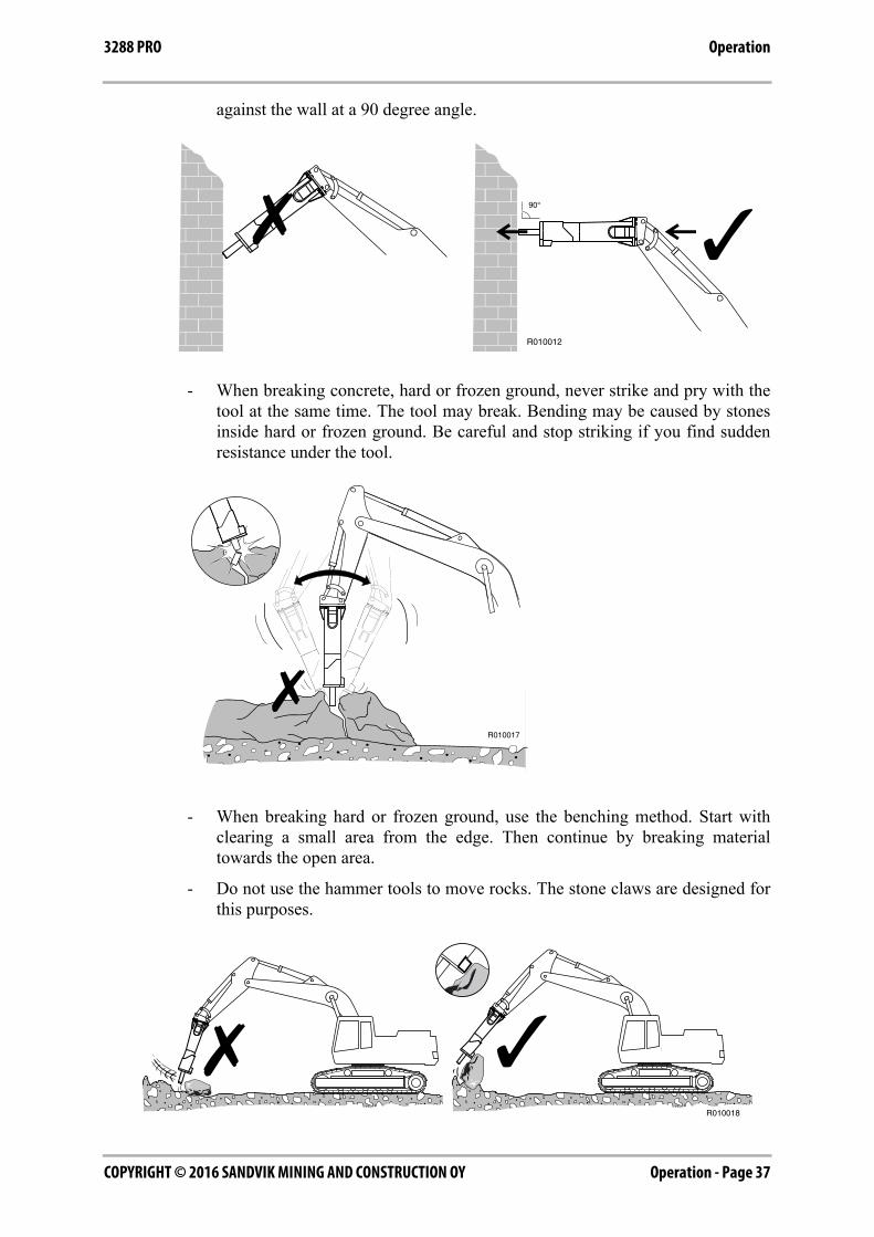
- When demolishing vertical structures (such as brick walls), place the tool
Operation - Page 37COPYRIGHT © 2016 SANDVIK MINING AND CONSTRUCTION OY
Operation3288 PRO
against the wall at a 90 degree angle.
- When breaking concrete, hard or frozen ground, never strike and pry with thetool at the same time. The tool may break. Bending may be caused by stonesinside hard or frozen ground. Be careful and stop striking if you find suddenresistance under the tool.
- When breaking hard or frozen ground, use the benching method. Start withclearing a small area from the edge. Then continue by breaking materialtowards the open area.
- Do not use the hammer tools to move rocks. The stone claws are designed forthis purposes.
���
���
COPYRIGHT © 2016 SANDVIK MINING AND CONSTRUCTION OYPage 38 - Operation
Operation 3288 PRO
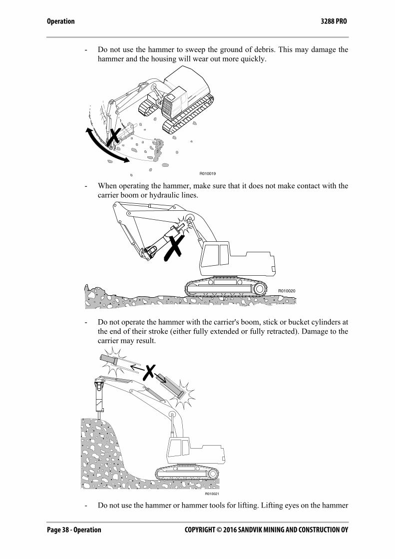
- Do not use the hammer to sweep the ground of debris. This may damage thehammer and the housing will wear out more quickly.
- When operating the hammer, make sure that it does not make contact with thecarrier boom or hydraulic lines.
- Do not operate the hammer with the carrier's boom, stick or bucket cylinders atthe end of their stroke (either fully extended or fully retracted). Damage to thecarrier may result.
- Do not use the hammer or hammer tools for lifting. Lifting eyes on the hammer

Operation - Page 39COPYRIGHT © 2016 SANDVIK MINING AND CONSTRUCTION OY
Operation3288 PRO
are for storage and maintenance purposes only.
- Check the service interval status weekly. See “Checking the service intervalstatus” on page 32.
WORKING PROCEDURE
Warning! Protect yourself and your neighbourhood against flying chips ofrock. Do not operate the hammer or carrier if someone is too close to thehammer.
Do not use the PRO-models hammer under water. If water fills the space wherethe piston strikes the tool, this generates a strong pressure wave that maydamage the hammer.
Warning! To avoid falling objects, do not use the product to lift other products.The lifting eyes located on the product housing are to be used solely to lift orhandle the product itself. See “Lifting instructions” on page 7.
1. Prepare the carrier for normal excavation work. Move the carrier to the requiredposition. Set the drive to neutral.
2. Set the engine speed to the recommended engine RPM for correct amount of oilsupply.
3. Carefully operate the carrier controls to place the hammer and boom into thebreaking position. Quick and careless boom movements can result in damage tothe hammer.
4. Use the excavator boom to press the hammer firmly against the object. Do notpry the hammer with the boom. Do not press too hard or too gently with theboom. The correct force is applied, when the tracks start to lift slightly from theground.
5. Place the tool against the object at a 90 degree angle. Avoid small irregularitieson the object which will break easily and cause either idle strokes or anincorrect working angle.
6. Start the hammer.
COPYRIGHT © 2016 SANDVIK MINING AND CONSTRUCTION OYPage 40 - Operation
Operation 3288 PRO
7. Stop the hammer quickly. Do not allow the hammer to fall down and make idlestrokes when an object breaks. Frequent idle strokes have a deteriorating effecton the hammer. If the hammer falls through, the housing wears out morequickly.
6.3 MOUNTING AND DISMOUNTING THE HAMMER
REMOVAL FROM CARRIER
Warning! The hammer must be secured from rolling over when disconnectingfrom the carrier. Only use a skilled operator to position the carrier for hammerremoval!
Warning! Hydraulic pressure inside the hammer must always be releasedbefore opening hose connections!
Warning! Hot hydraulic fluid can cause severe injuries!
1. Position hammer horizontally on the floor. If the hammer is going to service,remove the tool.
2. Stop the carrier engine. Operate boom and hammer controls to release pressuretrapped inside hoses. Wait ten minutes for oil pressure to drop.
3. Close hammer inlet and outlet lines. If quick couplers are used, disconnectionautomatically closes hammer lines. If hammer line includes ball valves, pleasemake sure that they are closed.
4. Disconnect hoses. Protect environment from oil spills. Plug the hoses and thehammer inlet and outlet ports to keep dirt out from hydraulic circuit.
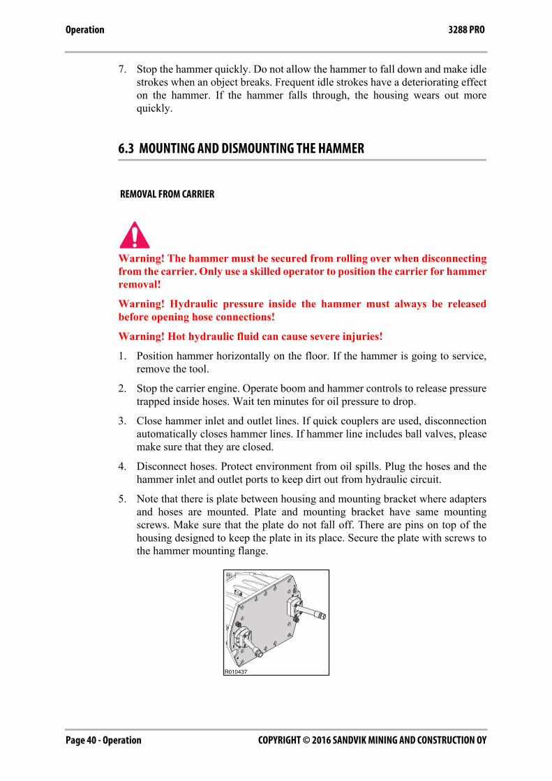
5. Note that there is plate between housing and mounting bracket where adaptersand hoses are mounted. Plate and mounting bracket have same mountingscrews. Make sure that the plate do not fall off. There are pins on top of thehousing designed to keep the plate in its place. Secure the plate with screws tothe hammer mounting flange.
R010437
Operation - Page 41COPYRIGHT © 2016 SANDVIK MINING AND CONSTRUCTION OY
Operation3288 PRO
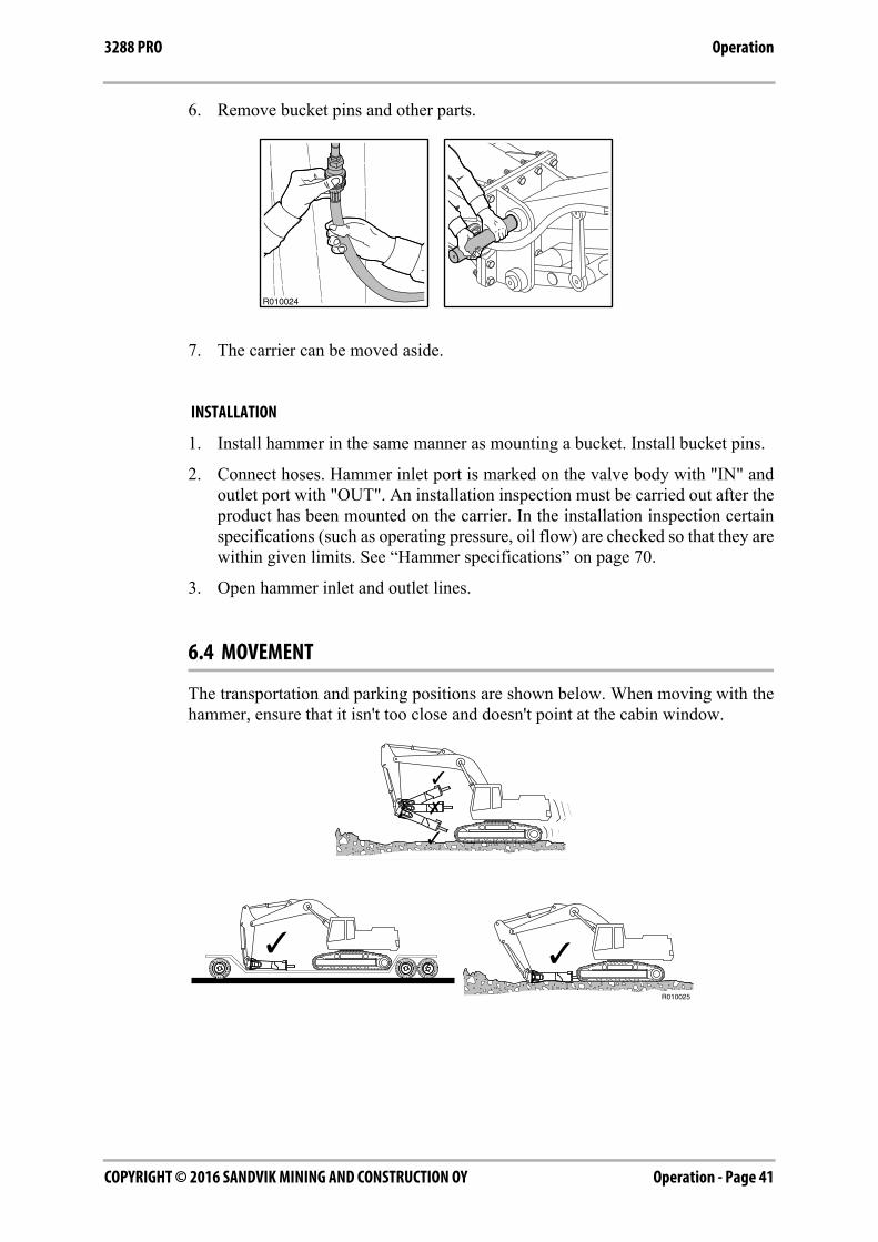
6. Remove bucket pins and other parts.
7. The carrier can be moved aside.
INSTALLATION
1. Install hammer in the same manner as mounting a bucket. Install bucket pins.
2. Connect hoses. Hammer inlet port is marked on the valve body with "IN" andoutlet port with "OUT". An installation inspection must be carried out after theproduct has been mounted on the carrier. In the installation inspection certainspecifications (such as operating pressure, oil flow) are checked so that they arewithin given limits. See “Hammer specifications” on page 70.
3. Open hammer inlet and outlet lines.
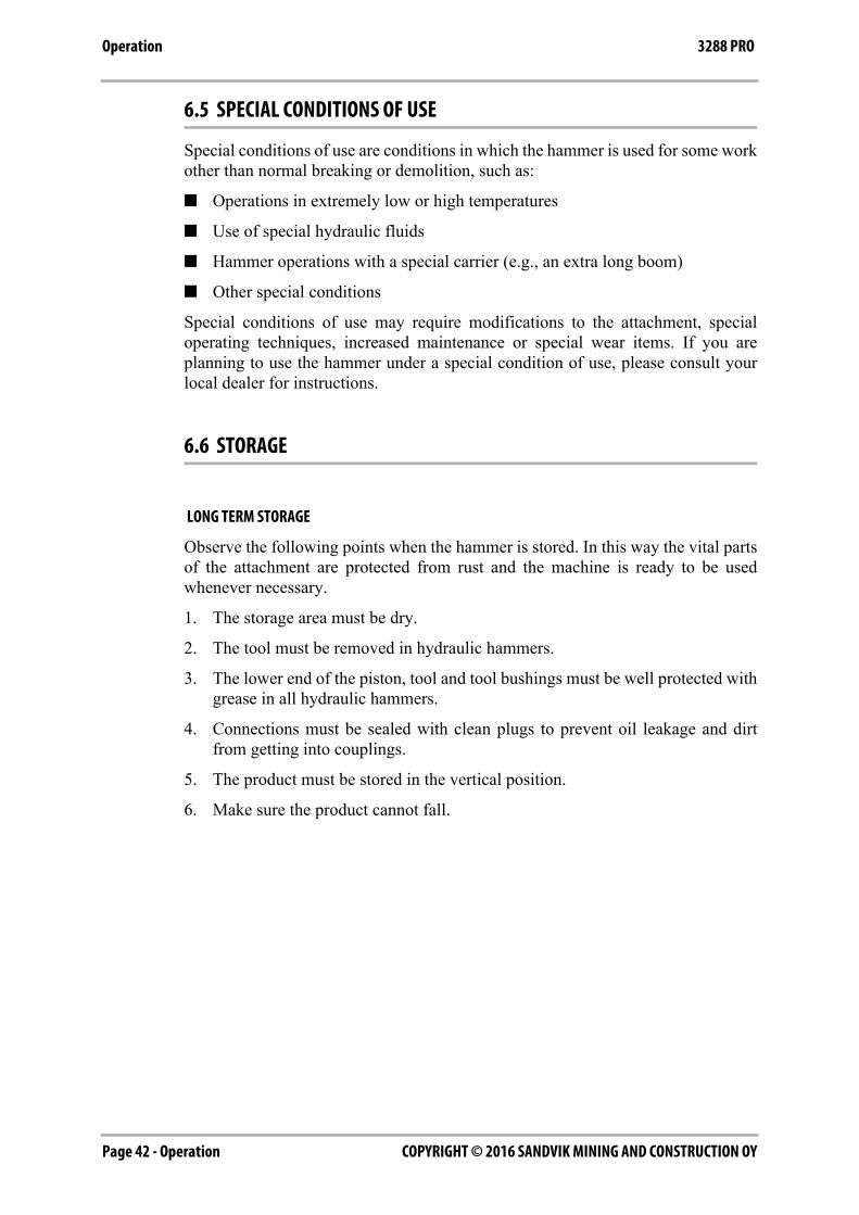
6.4 MOVEMENT
The transportation and parking positions are shown below. When moving with thehammer, ensure that it isn't too close and doesn't point at the cabin window.
COPYRIGHT © 2016 SANDVIK MINING AND CONSTRUCTION OYPage 42 - Operation
Operation 3288 PRO
6.5 SPECIAL CONDITIONS OF USE
Special conditions of use are conditions in which the hammer is used for some workother than normal breaking or demolition, such as:
■ Operations in extremely low or high temperatures
■ Use of special hydraulic fluids
■ Hammer operations with a special carrier (e.g., an extra long boom)
■ Other special conditions
Special conditions of use may require modifications to the attachment, specialoperating techniques, increased maintenance or special wear items. If you areplanning to use the hammer under a special condition of use, please consult yourlocal dealer for instructions.
6.6 STORAGE
LONG TERM STORAGE
Observe the following points when the hammer is stored. In this way the vital partsof the attachment are protected from rust and the machine is ready to be usedwhenever necessary.
1. The storage area must be dry.
2. The tool must be removed in hydraulic hammers.
3. The lower end of the piston, tool and tool bushings must be well protected withgrease in all hydraulic hammers.
4. Connections must be sealed with clean plugs to prevent oil leakage and dirtfrom getting into couplings.
5. The product must be stored in the vertical position.
6. Make sure the product cannot fall.
Lubrication - Page 43COPYRIGHT © 2016 SANDVIK MINING AND CONSTRUCTION OY
3288 PRO
LUBRICATION

COPYRIGHT © 2016 SANDVIK MINING AND CONSTRUCTION OYPage 44 - Lubrication
Hammer tool greasing 3288 PRO
1. HAMMER TOOL GREASING
1.1 RECOMMENDED GREASES
Wear gloves when handling the grease containers. If you get grease onto yourskin, wash it away with water.
1.2 MANUAL GREASING
Follow the product's greasing instructions and avoid excessive greasing.Dispose of empty grease containers appropriately.
Manual greasing is always possible even if the hammer is equipped with theautomatic greasing device. Manual greasing is necessary if there is no greaseavailable for the greasing device, greasing device has malfunction or pressure hoseis damaged. Check also the grease hose conditions inside the housing.
GREASING INTERVAL
1. Tool shank must be well lubricated before installing tool.
2. 5-10 strokes from grease gun to tool bushings and tool at regular intervals.
3. Adapt interval and amount of grease to wear rate of tool and workingconditions. This can be anything between two hours and daily, depending onmaterial (rock/concrete) to be broken. See “Recommended greases” on page 44.
R020112
Lubrication - Page 45COPYRIGHT © 2016 SANDVIK MINING AND CONSTRUCTION OY
Hammer tool greasing3288 PRO
Insufficient greasing or improper grease may cause:
■ Abnormal wear of tool bushing and tool
■ Tool breakage
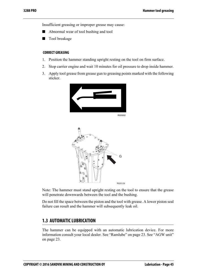
CORRECT GREASING
1. Position the hammer standing upright resting on the tool on firm surface.
2. Stop carrier engine and wait 10 minutes for oil pressure to drop inside hammer.
3. Apply tool grease from grease gun to greasing points marked with the followingsticker.
Note: The hammer must stand upright resting on the tool to ensure that the greasewill penetrate downwards between the tool and the bushing.
Do not fill the space between the piston and the tool with grease. A lower piston sealfailure can result and the hammer will subsequently leak oil.
1.3 AUTOMATIC LUBRICATION
The hammer can be equipped with an automatic lubrication device. For moreinformation consult your local dealer. See “Ramlube” on page 23. See “AGW unit”on page 23.
G
R020129
COPYRIGHT © 2016 SANDVIK MINING AND CONSTRUCTION OYPage 46 - Lubrication
Carrier hydraulic oil 3288 PRO
2. CARRIER HYDRAULIC OIL
2.1 REQUIREMENTS FOR HYDRAULIC OIL
GENERAL REQUIREMENTS
In general the hydraulic oil originally intended for the carrier can be used with thisproduct. However, since working with the product heats the oil more than the usualexcavation work, the temperature of the oil must be monitored.
If the temperature of the hydraulic oil exceeds 80 °C (176 °F), an auxiliary oil cooleris needed. The oil viscosity must be between 20-1000 cSt while the attachment isbeing used.
When the product is used continuously, the temperature of the hydraulic oilnormalizes at a certain level depending on conditions and on the carrier. Thetemperature in the tank must not exceed the maximum allowed.
The hammer must not be started if the ambient temperature is below freezing andthe oil is very thick. The machine must be moved to bring the oil temperature above0 °C (32 °F) before hammering can start (viscosity 1000 cSt or 131 °E).
Lubrication - Page 47COPYRIGHT © 2016 SANDVIK MINING AND CONSTRUCTION OY
Carrier hydraulic oil3288 PRO
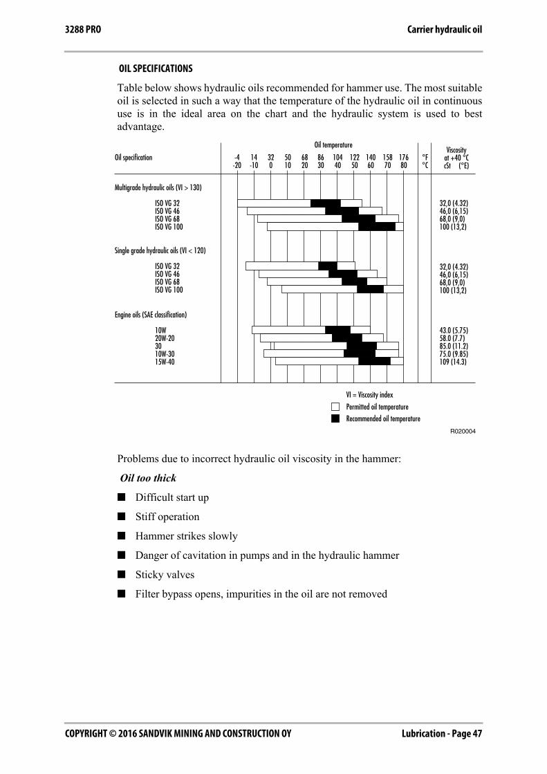
OIL SPECIFICATIONS
Table below shows hydraulic oils recommended for hammer use. The most suitableoil is selected in such a way that the temperature of the hydraulic oil in continuoususe is in the ideal area on the chart and the hydraulic system is used to bestadvantage.
Problems due to incorrect hydraulic oil viscosity in the hammer:
Oil too thick
■ Difficult start up
■ Stiff operation
■ Hammer strikes slowly
■ Danger of cavitation in pumps and in the hydraulic hammer
■ Sticky valves
■ Filter bypass opens, impurities in the oil are not removed
COPYRIGHT © 2016 SANDVIK MINING AND CONSTRUCTION OYPage 48 - Lubrication
Carrier hydraulic oil 3288 PRO
Oil too thin
■ Efficiency losses (internal leaks)
■ Damage to gaskets and seals, leaks
■ Accelerated wearing of parts, because of decreased lubrication efficiency
■ Hammer strikes irregularly and slowly
■ Danger of cavitation in pumps and in the hydraulic hammer
Note: We strongly recommend the use of different hydraulic oils in the summer andin the winter if there is an average temperature difference of more than 35 °C (63°F). The correct hydraulic oil viscosity is thus ensured.
SPECIAL OILS
In some cases special oils (for example biological oils and non-inflammable oils)can be used with hydraulic hammers. Observe the following aspects whenconsidering the use of special oils:
■ The viscosity range in the special oil must be in the given range (20-1000 cSt)
■ The lubrication properties must be sufficient
■ The corrosion resistance properties must be good enough
Note: Although a special oil could be used in the carrier, always check its suitabilitywith the hammer due to high piston speed of the hammer. Contact the oilmanufacturer or your local dealer for more information about special oils.
2.2 OIL COOLER
The correct place to connect the hammer return line is between the oil cooler andthe main filters. The hammer return line should not be connected before the oilcooler. Routing the hammer return flow through the cooler, might damage either thecooler, due to pulsating flow, or the hammer, due to increased back pressure.
The carrier hydraulic system must be able to maintain the temperature within anacceptable level during the hammer operation. This is for two reasons.
1. Seals, wipers, membranes and other parts manufactured from the correspondingmaterials can normally stand temperatures up to 80 °C (176 °F).
2. The higher the temperature is, the less viscous the oil gets thus losing itscapability to lubricate.

Lubrication - Page 49COPYRIGHT © 2016 SANDVIK MINING AND CONSTRUCTION OY
Carrier hydraulic oil3288 PRO
A standard carrier, with a proper hammer circuit, meets the requirements of thenecessary cooling capacity. If the oil temperature tends to be too high during thehammer operation, the following things must be checked:
■ The hammer circuit pressure relief valve is not open when the hammer isoperated.
■ The hammer circuit pressure drops are reasonable. Less than 10 bar (145 psi) inthe pressure line and less than 5 bar (75 psi) in the return line.
■ Hydraulic pumps, valves, cylinders, motors etc. and hammer do not haveinternal leakages.
If all of the above mentioned things are in order, and the temperature of thehydraulic oil still tends to be too high, extra cooling capacity is needed. Consult thecarrier manufacturer or dealer for details.
2.3 OIL FILTER
The purpose of the oil filter is to remove impurities from the hydraulic oil. Air andwater are also impurities in oil. Not all impurities can be seen with the naked eye.
Impurities enter the hydraulic system:
■ During hydraulic oil changes and refilling.
■ When components are repaired or serviced.
■ When the hammer is being installed on the carrier.
■ Because of component wear.
Normally the existing main oil filters of the carrier are used as hammer circuit returnline filters. Consult the carrier manufacturer or your local dealer concerninginstructions for the filter change intervals.
In hydraulic hammer work the carrier oil filter must fulfil the followingspecifications:
■ The oil filter must allow maximum particle size of 25 microns (0.025 mm).
■ The oil filter material must be artificial fibre cloth or very fine gauge metallicmesh to withstand pressure fluctuations.
■ The oil filter must have a nominal flow capacity of at least twice the hammer'smaximum flow.
In general, oil companies guarantee new oils to have a particle count of 40 micronsmaximum. Filter the oil when filling the tank.
The damage caused by hydraulic oil impurities in the carrier and hammer circuits:
1. The working life of the pumps and other components is significantly shortened.
■ Rapid wear of parts.
■ Cavitation.
2. Wear of cylinder and gaskets.
COPYRIGHT © 2016 SANDVIK MINING AND CONSTRUCTION OYPage 50 - Lubrication
Carrier hydraulic oil 3288 PRO
3. Reduced hammer efficiency.
■ Accelerated wear of moving parts and seals.
■ Danger of piston seizing up.
■ Oil leakages.
4. Shortened working life and reduced lubricating capability of oil.
■ Oil overheats.
■ Oil quality deteriorates.
■ Electro-chemical changes in hydraulic oil.
5. Valves do not function properly.
■ Spools bind.
■ Rapid wear of parts.
■ Blocking of small holes.
Note: Component damage is only a symptom. The trouble itself will not be curedby removing the symptom. After any component damage due to impurities in theoil, the entire hydraulic system has to be cleaned. Dismantle, clean and reassemblethe hammer and change the hydraulic oil.
Maintenance - Page 51COPYRIGHT © 2016 SANDVIK MINING AND CONSTRUCTION OY
3288 PRO
MAINTENANCE
COPYRIGHT © 2016 SANDVIK MINING AND CONSTRUCTION OYPage 52 - Maintenance
Routine maintenance 3288 PRO
1. ROUTINE MAINTENANCE
1.1 OVERVIEW
This product is a precision made hydraulic machine. Therefore great care andcleanliness should be taken when handling any of the hydraulic components. Dirt isthe worst enemy in hydraulic systems.
Handle the parts carefully and remember to cover any cleaned and dried parts withclean lint-free cloth. Do not use anything other than purpose designed materials forcleaning hydraulic parts. Never use water, paint thinners or carbon tetrachloride.
Components, gaskets and seals in the hydraulic system should be oiled with cleanhydraulic oil before assembly.
1.2 INSPECTION AND MAINTENANCE BY THE OPERATOR
Note: The time intervals given refer to the carrier hours while the attachment isinstalled.
EVERY 10 HOURS OR AT LEAST ONCE A WEEK
■ Remove the tool retaining pin and the tool and check their condition. Grind theburrs away if necessary. See “Changing the tool” on page 56.
■ Check condition of the tool seal. Smoothen with emery cloth (grit sizeP120...P150), if necessary.
■ Check that the tool has received sufficient greasing. Ensure proper operation ofthe greasing device and correct amount of supplied grease.
■ Check air supply from the compressor.
■ Check condition of water spray nozzle.
■ Check that water spray pipes mounting screws tightening torque are asspecified. Tightening torque is 180 Nm
Maintenance - Page 53COPYRIGHT © 2016 SANDVIK MINING AND CONSTRUCTION OY
Routine maintenance3288 PRO
EVERY 50 HOURS OR AT LEAST ONCE A MONTH
■ Check the tool shank and tool bushings for wear. See “Changing the tool” onpage 56. See “Bronze insert of TS bushing” on page 59.
■ Check the hydraulic hoses. Replace if necessary. Do not let dirt get into thehammer or hoses.
■ Open the covers and check that the hammer moves normally inside the housingand that vibration dampening elements (pads and buffers) are in good condition.
■ Check the condition of guide plates by moving hammer with a pry bar from sideto side inside housing. The maximum allowed clearance is approximately ±3.5mm.
■ Check the condition of the housing cover seals and replace if necessary.
1.3 INSPECTION AND MAINTENANCE BY THE DEALER
Note: The times given refer to the carrier hours while the attachment is installed.
INITIAL 50-HOUR INSPECTION
It is recommended to have the first inspection done by your local dealer after 50 to100 operating hours. Contact your local dealer for more information about the initial50-hour inspection.
EVERY 400 HOURS
This service is recommended to be done by your local dealer after 400 operatinghours or at least once a year. Neglecting the annual service can cause severe damageto the hammer.
Your local dealer will reseal the hammer, replace the accumulator membranes andreplace safety decals as needed. Contact your local dealer for more informationabout annual servicing.
During this maintenance you should do the following tasks.
■ Check all hydraulic connections.
■ Check that the hydraulic hoses do not rub against anything in any boomposition.
■ Replace and inspect the hydraulic oil filters of the carrier.
COPYRIGHT © 2016 SANDVIK MINING AND CONSTRUCTION OYPage 54 - Maintenance
Routine maintenance 3288 PRO
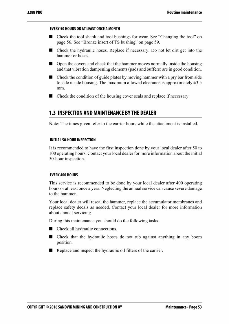
1.4 DISASSEMBLING AND ASSEMBLING HOUSING COVERS
SPECIFICATION FOR COVER MOUNTING SCREWS
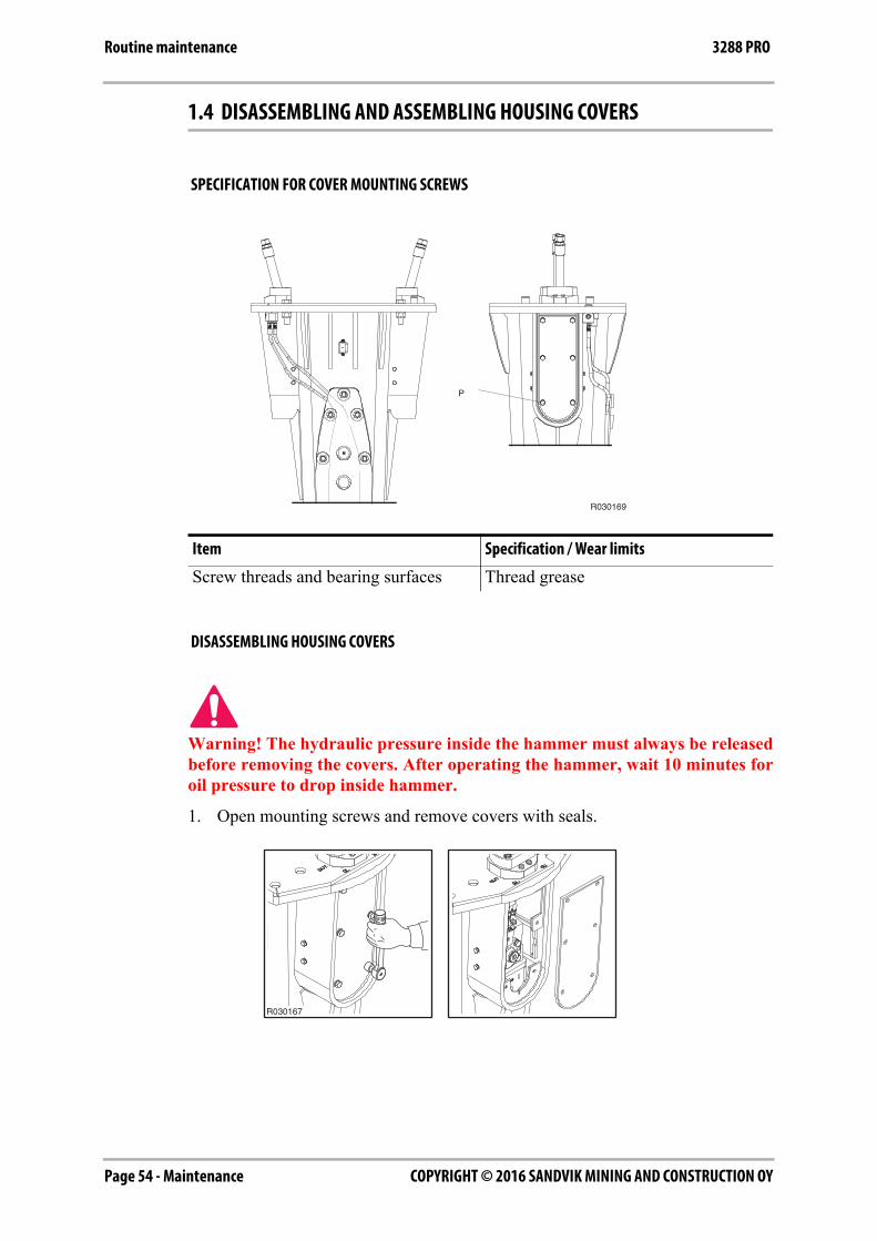
DISASSEMBLING HOUSING COVERS
Warning! The hydraulic pressure inside the hammer must always be releasedbefore removing the covers. After operating the hammer, wait 10 minutes foroil pressure to drop inside hammer.
1. Open mounting screws and remove covers with seals.
Item Specification / Wear limits
Screw threads and bearing surfaces Thread grease
R030169
P
R030167
Maintenance - Page 55COPYRIGHT © 2016 SANDVIK MINING AND CONSTRUCTION OY
Routine maintenance3288 PRO
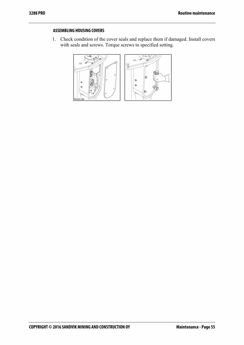
ASSEMBLING HOUSING COVERS
1. Check condition of the cover seals and replace them if damaged. Install coverswith seals and screws. Torque screws to specified setting.
R030168
COPYRIGHT © 2016 SANDVIK MINING AND CONSTRUCTION OYPage 56 - Maintenance
Changing the tool 3288 PRO
2. CHANGING THE TOOL
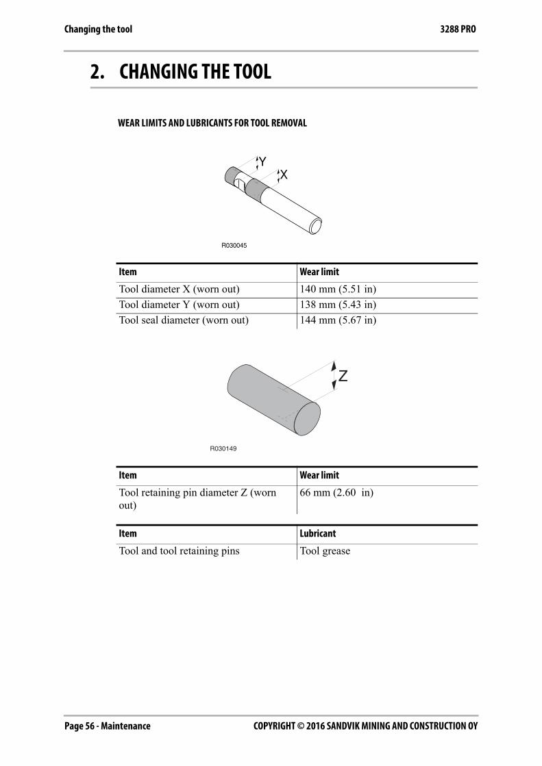
WEAR LIMITS AND LUBRICANTS FOR TOOL REMOVAL
Item Wear limit
Tool diameter X (worn out) 140 mm (5.51 in)
Tool diameter Y (worn out) 138 mm (5.43 in)
Tool seal diameter (worn out) 144 mm (5.67 in)
Item Wear limit
Tool retaining pin diameter Z (worn out)
66 mm (2.60 in)
Item Lubricant
Tool and tool retaining pins Tool grease
R030149
Z

Maintenance - Page 57COPYRIGHT © 2016 SANDVIK MINING AND CONSTRUCTION OY
Changing the tool3288 PRO
REMOVAL OF TOOL
Warning! The hydraulic pressure inside the hammer must always be releasedbefore removing the tool. After operating the hammer, wait 10 minutes for oilpressure to drop inside hammer.
Warning! Hot tool can cause severe injuries.
Do not throw used hammer tool away at job site. Used tools can be recycled bydelivering them to an authorized scrap metal collection facility.
1. Set the hammer on level ground.
2. Make sure the carrier's transmission is in neutral and the parking brake isengaged.
3. Stop the carrier engine.
4. Remove plugs.
5. Remove rubber rings.
6. Remove tool retaining pins by using t-puller.
7. Remove tool. Use lifting device if necessary. If the tool cannot be removedcontact your local dealer.
R030150
R030151
COPYRIGHT © 2016 SANDVIK MINING AND CONSTRUCTION OYPage 58 - Maintenance
Changing the tool 3288 PRO
Note: If hammer is still on carrier, it may be easier to stick the tool in the groundand lift the hammer off the tool. Make sure that the tool cannot fall.
INSTALLATION OF TOOL
1. Clean all parts carefully.
2. Measure the tool diameters (X and Y) from the areas marked on the illustration.Replace tool if necessary. See “Changing the tool” on page 56.
3. Measure the tool retaining pin diameter (Z). Replace tool if necessary. See“Changing the tool” on page 56.
4. Check the tool seal surface condition. If seal is damaged replace it.
5. Check the shape of the seal. It should be round, not oval in shape.
6. Measure seal inner diameter from area with most wear. Replace it if not asspecified.
7. If the shape developes oval, the seal should be removed from its groove and thegroove cleaned thoroughly. If old seal is reinstalled, diameter needs to bechecked again.
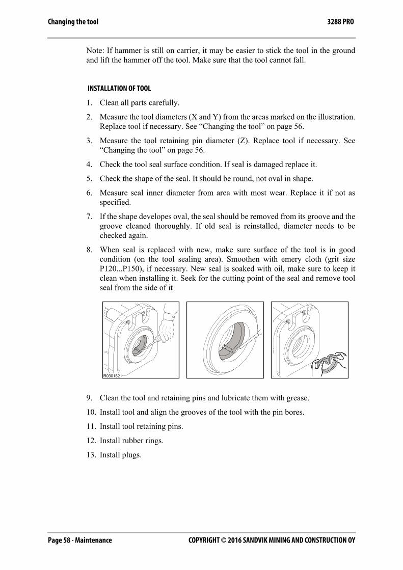
8. When seal is replaced with new, make sure surface of the tool is in goodcondition (on the tool sealing area). Smoothen with emery cloth (grit sizeP120...P150), if necessary. New seal is soaked with oil, make sure to keep itclean when installing it. Seek for the cutting point of the seal and remove toolseal from the side of it
9. Clean the tool and retaining pins and lubricate them with grease.
10. Install tool and align the grooves of the tool with the pin bores.
11. Install tool retaining pins.
12. Install rubber rings.
13. Install plugs.
R030152
Maintenance - Page 59COPYRIGHT © 2016 SANDVIK MINING AND CONSTRUCTION OY
Bronze insert of TS bushing3288 PRO
3. BRONZE INSERT OF TS BUSHING
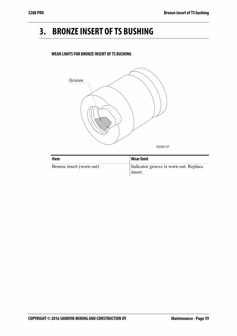
WEAR LIMITS FOR BRONZE INSERT OF TS BUSHING
Item Wear limit
Bronze insert (worn out) Indicator groove is worn out. Replace insert.
R030137
COPYRIGHT © 2016 SANDVIK MINING AND CONSTRUCTION OYPage 60 - Maintenance
Bronze insert of TS bushing 3288 PRO
REMOVAL OF BRONZE INSERT
Warning! The hydraulic pressure inside the hammer must always be releasedbefore removing the tool. After operating the hammer, wait 10 minutes for oilpressure to drop inside hammer.
Warning! Hot tool can cause severe injuries.
Do not throw used hammer tool or other parts away at job site. Used tools canbe recycled by delivering them to an authorized scrap metal collection facility.
Note: When you install a new bronze insert, it is strongly recommended to use a newtool.
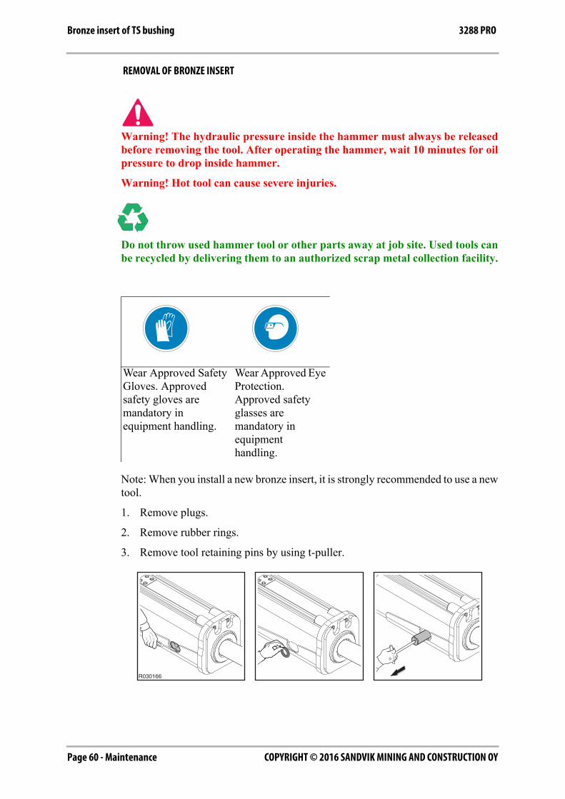
1. Remove plugs.
2. Remove rubber rings.
3. Remove tool retaining pins by using t-puller.
Wear Approved Safety Gloves. Approved safety gloves are mandatory in equipment handling.
Wear Approved Eye Protection. Approved safety glasses are mandatory in equipment handling.
R030166
Maintenance - Page 61COPYRIGHT © 2016 SANDVIK MINING AND CONSTRUCTION OY
Bronze insert of TS bushing3288 PRO
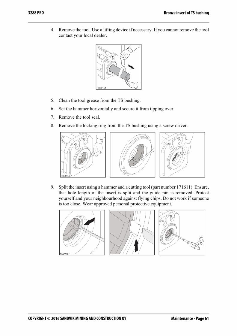
4. Remove the tool. Use a lifting device if necessary. If you cannot remove the toolcontact your local dealer.
5. Clean the tool grease from the TS bushing.
6. Set the hammer horizontally and secure it from tipping over.
7. Remove the tool seal.
8. Remove the locking ring from the TS bushing using a screw driver.
9. Split the insert using a hammer and a cutting tool (part number 171611). Ensure,that hole length of the insert is split and the guide pin is removed. Protectyourself and your neighbourhood against flying chips. Do not work if someoneis too close. Wear approved personal protective equipment.
R030151
R030155
R030157
COPYRIGHT © 2016 SANDVIK MINING AND CONSTRUCTION OYPage 62 - Maintenance
Bronze insert of TS bushing 3288 PRO
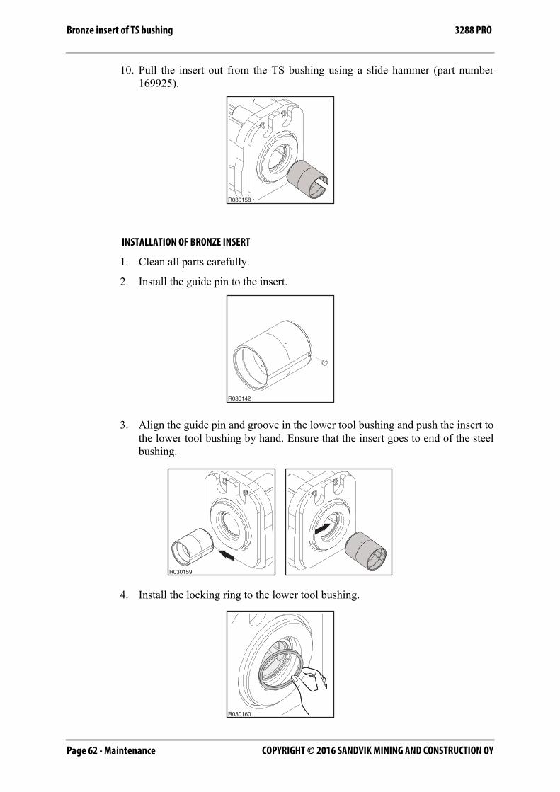
10. Pull the insert out from the TS bushing using a slide hammer (part number169925).
INSTALLATION OF BRONZE INSERT
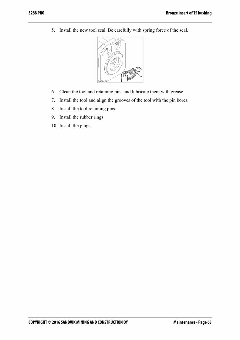
1. Clean all parts carefully.
2. Install the guide pin to the insert.
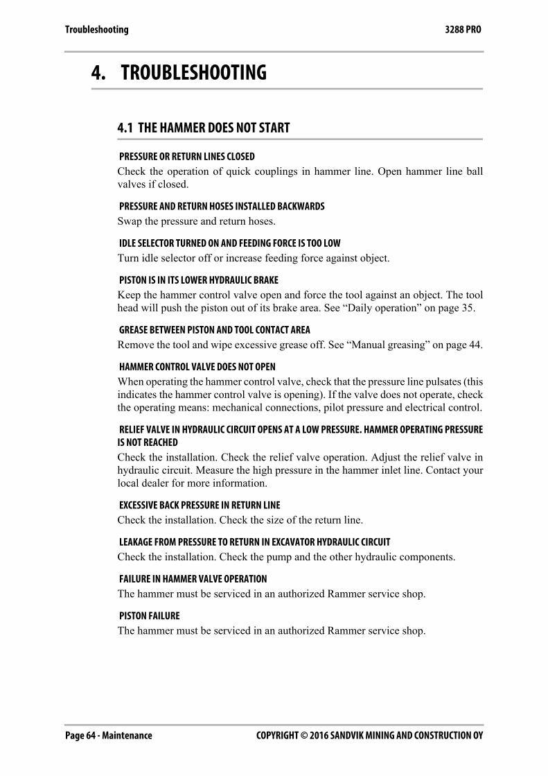
3. Align the guide pin and groove in the lower tool bushing and push the insert tothe lower tool bushing by hand. Ensure that the insert goes to end of the steelbushing.
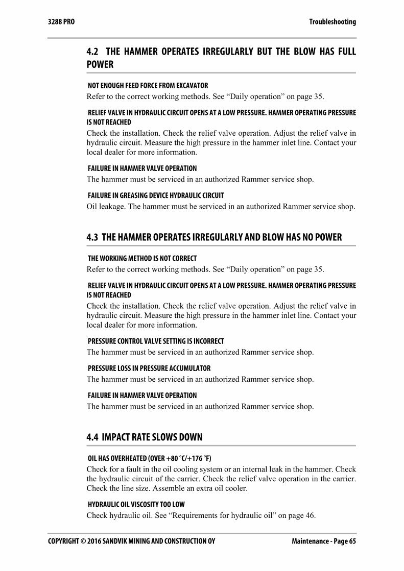
4. Install the locking ring to the lower tool bushing.
R030158
R030142
R030159
R030160
Maintenance - Page 63COPYRIGHT © 2016 SANDVIK MINING AND CONSTRUCTION OY
Bronze insert of TS bushing3288 PRO
5. Install the new tool seal. Be carefully with spring force of the seal.
6. Clean the tool and retaining pins and lubricate them with grease.
7. Install the tool and align the grooves of the tool with the pin bores.
8. Install the tool retaining pins.
9. Install the rubber rings.
10. Install the plugs.
R030156
COPYRIGHT © 2016 SANDVIK MINING AND CONSTRUCTION OYPage 64 - Maintenance
Troubleshooting 3288 PRO
4. TROUBLESHOOTING
4.1 THE HAMMER DOES NOT START
PRESSURE OR RETURN LINES CLOSEDCheck the operation of quick couplings in hammer line. Open hammer line ballvalves if closed.
PRESSURE AND RETURN HOSES INSTALLED BACKWARDSSwap the pressure and return hoses.
IDLE SELECTOR TURNED ON AND FEEDING FORCE IS TOO LOWTurn idle selector off or increase feeding force against object.
PISTON IS IN ITS LOWER HYDRAULIC BRAKEKeep the hammer control valve open and force the tool against an object. The toolhead will push the piston out of its brake area. See “Daily operation” on page 35.
GREASE BETWEEN PISTON AND TOOL CONTACT AREARemove the tool and wipe excessive grease off. See “Manual greasing” on page 44.
HAMMER CONTROL VALVE DOES NOT OPENWhen operating the hammer control valve, check that the pressure line pulsates (thisindicates the hammer control valve is opening). If the valve does not operate, checkthe operating means: mechanical connections, pilot pressure and electrical control.
RELIEF VALVE IN HYDRAULIC CIRCUIT OPENS AT A LOW PRESSURE. HAMMER OPERATING PRESSUREIS NOT REACHEDCheck the installation. Check the relief valve operation. Adjust the relief valve inhydraulic circuit. Measure the high pressure in the hammer inlet line. Contact yourlocal dealer for more information.
EXCESSIVE BACK PRESSURE IN RETURN LINECheck the installation. Check the size of the return line.
LEAKAGE FROM PRESSURE TO RETURN IN EXCAVATOR HYDRAULIC CIRCUITCheck the installation. Check the pump and the other hydraulic components.
FAILURE IN HAMMER VALVE OPERATIONThe hammer must be serviced in an authorized Rammer service shop.
PISTON FAILUREThe hammer must be serviced in an authorized Rammer service shop.
Maintenance - Page 65COPYRIGHT © 2016 SANDVIK MINING AND CONSTRUCTION OY
Troubleshooting3288 PRO
4.2 THE HAMMER OPERATES IRREGULARLY BUT THE BLOW HAS FULLPOWER
NOT ENOUGH FEED FORCE FROM EXCAVATORRefer to the correct working methods. See “Daily operation” on page 35.
RELIEF VALVE IN HYDRAULIC CIRCUIT OPENS AT A LOW PRESSURE. HAMMER OPERATING PRESSUREIS NOT REACHEDCheck the installation. Check the relief valve operation. Adjust the relief valve inhydraulic circuit. Measure the high pressure in the hammer inlet line. Contact yourlocal dealer for more information.
FAILURE IN HAMMER VALVE OPERATIONThe hammer must be serviced in an authorized Rammer service shop.
FAILURE IN GREASING DEVICE HYDRAULIC CIRCUITOil leakage. The hammer must be serviced in an authorized Rammer service shop.
4.3 THE HAMMER OPERATES IRREGULARLY AND BLOW HAS NO POWER
THE WORKING METHOD IS NOT CORRECTRefer to the correct working methods. See “Daily operation” on page 35.
RELIEF VALVE IN HYDRAULIC CIRCUIT OPENS AT A LOW PRESSURE. HAMMER OPERATING PRESSUREIS NOT REACHEDCheck the installation. Check the relief valve operation. Adjust the relief valve inhydraulic circuit. Measure the high pressure in the hammer inlet line. Contact yourlocal dealer for more information.
PRESSURE CONTROL VALVE SETTING IS INCORRECTThe hammer must be serviced in an authorized Rammer service shop.
PRESSURE LOSS IN PRESSURE ACCUMULATORThe hammer must be serviced in an authorized Rammer service shop.
FAILURE IN HAMMER VALVE OPERATIONThe hammer must be serviced in an authorized Rammer service shop.
4.4 IMPACT RATE SLOWS DOWN
OIL HAS OVERHEATED (OVER +80 °C/+176 °F)Check for a fault in the oil cooling system or an internal leak in the hammer. Checkthe hydraulic circuit of the carrier. Check the relief valve operation in the carrier.Check the line size. Assemble an extra oil cooler.
HYDRAULIC OIL VISCOSITY TOO LOWCheck hydraulic oil. See “Requirements for hydraulic oil” on page 46.
COPYRIGHT © 2016 SANDVIK MINING AND CONSTRUCTION OYPage 66 - Maintenance
Troubleshooting 3288 PRO
EXCESSIVE BACK PRESSURE IN RETURN LINECheck the installation. Check the size of the return line.
RELIEF VALVE IN HYDRAULIC CIRCUIT OPENS AT A LOW PRESSURE. HAMMER OPERATING PRESSUREIS NOT REACHEDCheck the installation. Check the relief valve operation. Adjust the relief valve inhydraulic circuit. Measure the high pressure in the hammer inlet line. Contact yourlocal dealer for more information.
LEAKAGE FROM PRESSURE TO RETURN IN EXCAVATOR HYDRAULIC CIRCUITCheck the installation. Check the pump and the other hydraulic components.
PRESSURE LOSS IN PRESSURE ACCUMULATORThe hammer must be serviced in an authorized Rammer service shop.
FAILURE IN HAMMER VALVE OPERATIONThe hammer must be serviced in an authorized Rammer service shop.
4.5 THE HAMMER DOES NOT STOP OR HAS RUN-ON
INTERNAL OIL LEAK IN THE HAMMERThe hammer must be serviced in an authorized Rammer service shop.
FAILURE IN HAMMER CONTROL VALVE OPERATIONCheck the hammer control valve in the carrier.
4.6 OIL OVERHEATS
APPLICATION NOT CORRECT FOR HAMMERRefer to recommended use and to correct working methods. See “Daily operation”on page 35.
COOLING CAPACITY OF THE FACTORY OIL COOLER IS TOO SMALLAssemble an extra oil cooler.
RELIEF VALVE IN HYDRAULIC CIRCUIT OPENS AT A LOW PRESSURE. HAMMER OPERATING PRESSUREIS NOT REACHEDCheck the installation. Check the relief valve operation. Adjust the relief valve inhydraulic circuit. Measure the high pressure in the hammer inlet line. Contact yourlocal dealer for more information.
HYDRAULIC OIL VISCOSITY TOO LOWCheck hydraulic oil. See “Requirements for hydraulic oil” on page 46.
LEAKAGE FROM PRESSURE TO RETURN IN EXCAVATOR HYDRAULIC CIRCUITCheck the installation. Check the pump and the other hydraulic components.

Maintenance - Page 67COPYRIGHT © 2016 SANDVIK MINING AND CONSTRUCTION OY
Troubleshooting3288 PRO
INTERNAL OIL LEAK IN THE HAMMERThe hammer must be serviced in an authorized Rammer service shop.
EXCESSIVE BACK PRESSURE IN RETURN LINECheck the installation. Check the size of the return line.
4.7 RECURRENT TOOL FAILURE
APPLICATION NOT CORRECT FOR HAMMERRefer to recommended use and to correct working methods. See “Operatinginstructions” on page 26.
ROUGH OPERATING PRACTICESRefer to recommended use and to correct working methods. See “Daily operation”on page 35.
TOOL DOES NOT GET ENOUGH LUBRICANTRefer to recommended use and to correct working methods.
RAPID WEAR OF TOOLRefer to recommended use and to correct working methods. See “Daily operation”on page 35. There is a wider selection of tools available for different applications.Consult with your local dealer for more information.
4.8 FURTHER ASSISTANCE
FURTHER ASSISTANCEIf further assistance is required, please prepare to answer the following questionsbefore calling your dealer.
■ Model and serial number
■ Working hours and service history
■ Ramdata report if available
■ Carrier model
■ Installation: Oil flow, operating pressure and return line pressure if known
■ Application
■ Has the product operated normally before

COPYRIGHT © 2016 SANDVIK MINING AND CONSTRUCTION OYPage 68 - Maintenance
Troubleshooting 3288 PRO

Specifications - Page 69COPYRIGHT © 2016 SANDVIK MINING AND CONSTRUCTION OY
3288 PRO
SPECIFICATIONS

COPYRIGHT © 2016 SANDVIK MINING AND CONSTRUCTION OYPage 70 - Specifications
Hammer specifications 3288 PRO
1. HAMMER SPECIFICATIONS
1.1 TECHNICAL SPECIFICATIONS
Item Specification
Minimum working weight1
1. Includes average mounting bracket and standard tool
2600 kg (5730 lb)
Hammer weight 2240 kg (4940 lb)
Impact rate, Long stroke2
2. Actual impact frequency depends on oil flow, oil viscosity, temperature, and material to be broken
320...560 bpm
Impact rate, Short stroke3
3. Actual impact frequency depends on oil flow, oil viscosity, temperature, and material to be broken
380...630 bpm
Operating pressure4
4. Actual pressure depends on oil flow, oil viscosity, temperature, material to be broken and back pressure
135...145 bar (1960...2105 psi)
Pressure relief, min5
5. Minimum setting = actual operating pressure + 50 bar (730 psi)
220 bar (3190 psi)
Pressure relief, max 240 bar (3480 psi)
Oil flow range 160...230 l/min (42.3...60.8 gal/min)
Back pressure, max 10 bar (145 psi)
Input power 56 kW (75 hp)
Tool diameter 142 mm (5.59 in)
Pressure line connection (IN) ORFS ISO 8434-3 ( 1 11/16-12 UN )
Return line connection (OUT) ORFS ISO 8434-3 ( 1 11/16-12 UN )
Grease connection (G)6
6. Located on the same side of the valve body as the pressure line (IN) connection
BSPP-internal 3/8"
Air connection (A)7
7. Located on the same side of the valve body as the return line (OUT) connection
BSPP-internal 3/8"
Water connection (W)8
8. Located on the same side of the valve body as the return line (OUT) connection
BSPP-internal 1/2"
Pressure line size (minimum inner diameter)
32 mm (1.26 in)
Return line size (minimum inner diameter) 32 mm (1.26 in)
Optimum oil temperature 40...60 °C (104...140 °F)
Allowed oil temperature range -20...80 °C (-4...176 °F)
Optimum oil viscosity at operating temperature
30...60 cSt
Allowed oil viscosity range 20...1000 cSt
Carrier weight, allowed range9 28...45 t (61700...99200 lb)
Noise level, measured sound power level,
LWA10121 dB (121 dB)
Noise level, guaranteed sound power level,
LWA11125 dB (125 dB)
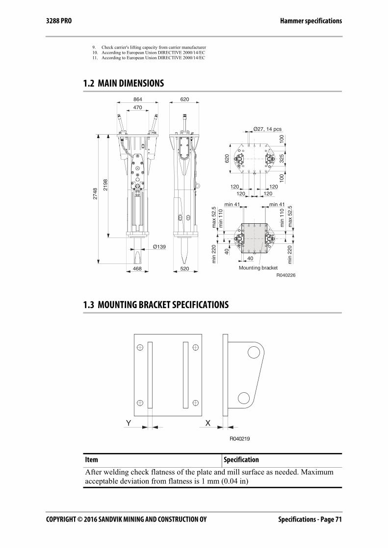
Specifications - Page 71COPYRIGHT © 2016 SANDVIK MINING AND CONSTRUCTION OY
Hammer specifications3288 PRO
1.2 MAIN DIMENSIONS
1.3 MOUNTING BRACKET SPECIFICATIONS
9. Check carrier's lifting capacity from carrier manufacturer10. According to European Union DIRECTIVE 2000/14/EC11. According to European Union DIRECTIVE 2000/14/EC
Item Specification
After welding check flatness of the plate and mill surface as needed. Maximum acceptable deviation from flatness is 1 mm (0.04 in)
R040226468 520
Ø139
864
470
62021
98
2748
Ø27, 14 pcs
120120120
120
620
325
100
100
min 41
min
110
min
220
40
min 41
min
110
40
min
220
max
52.
5
max
52.
5
Mounting bracket
R040219
XY
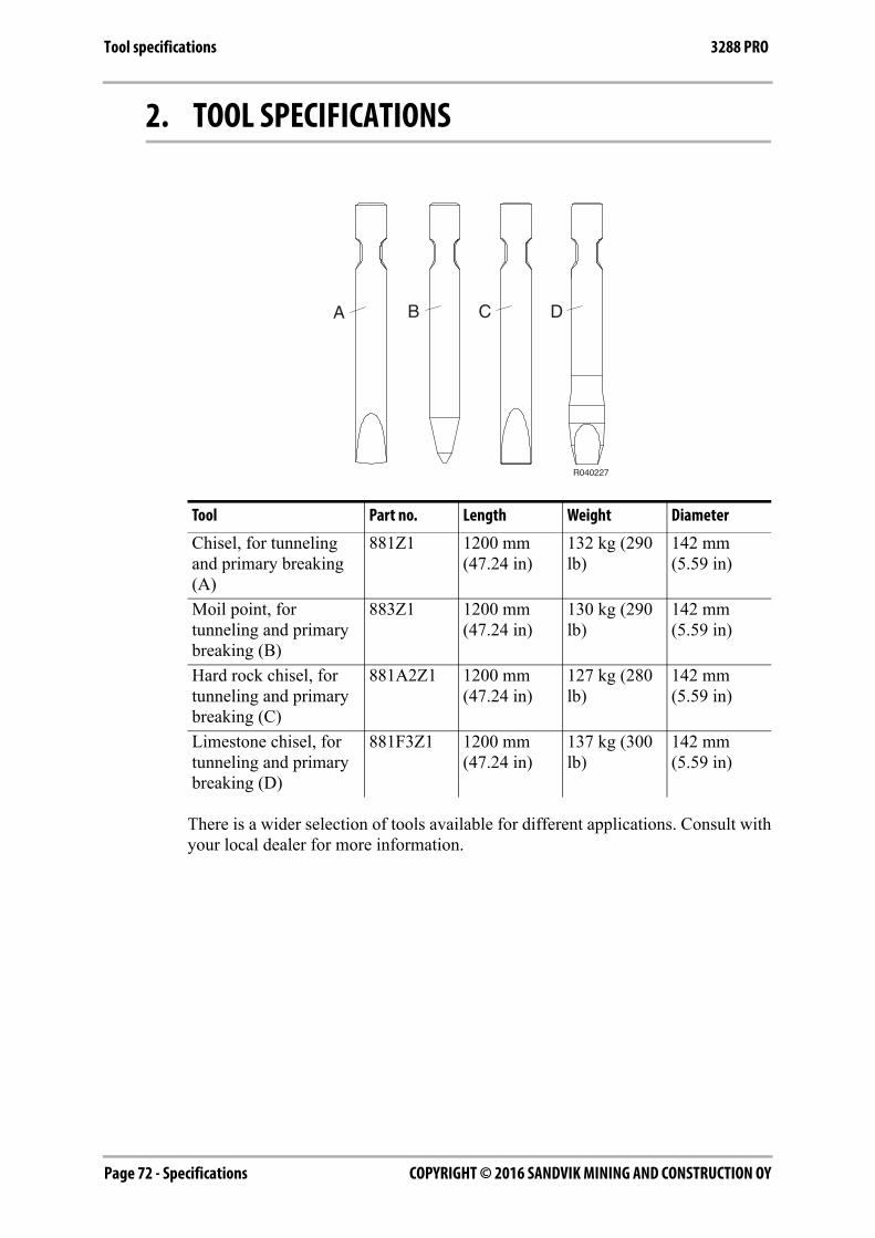
COPYRIGHT © 2016 SANDVIK MINING AND CONSTRUCTION OYPage 72 - Specifications
Tool specifications 3288 PRO
2. TOOL SPECIFICATIONS
There is a wider selection of tools available for different applications. Consult withyour local dealer for more information.
Tool Part no. Length Weight Diameter
Chisel, for tunneling and primary breaking (A)
881Z1 1200 mm (47.24 in)
132 kg (290 lb)
142 mm (5.59 in)
Moil point, for tunneling and primary breaking (B)
883Z1 1200 mm (47.24 in)
130 kg (290 lb)
142 mm (5.59 in)
Hard rock chisel, for tunneling and primary breaking (C)
881A2Z1 1200 mm (47.24 in)
127 kg (280 lb)
142 mm (5.59 in)
Limestone chisel, for tunneling and primary breaking (D)
881F3Z1 1200 mm (47.24 in)
137 kg (300 lb)
142 mm (5.59 in)
A B
R040227
DC
Specifications - Page 73COPYRIGHT © 2016 SANDVIK MINING AND CONSTRUCTION OY
CE mark and EC Declaration of Conformity3288 PRO
3. CE MARK AND EC DECLARATION OF CONFORMITYEC DECLARATION OF CONFORMITY
Original
(Directive 2006/42/EC, Annex II. 1. A; Directive 2000/14/EC)
Manufacturer: Sandvik Mining and Construction Oy, Breakers Lahti
Address: Taivalkatu 8, FI-15170 Lahti, Finland
Herewith declares that the Rammer hydraulic hammer
Model: 3288 PRO
- Is in conformity with all the relevant provisions of the Machinery Directive 2006/42/EC.
The procedure applied for the conformity assessment is "Assessment of conformity with internal checkson the manufacture of machinery" (Annex VIII). The risk assessment is made according to ISO 12100.The DNV certified quality management system according to ISO 9001 is applied to design andmanufacture of the product.
- Is in conformity with all the relevant provisions of the Outdoor Equipment Noise Directive 2000/14/EC.
The procedure applied for conformity assessment is "Internal control of production" (Annex V).
Technical file
N.N., Director R&D/E, is authorized to compile the technical file and confirms the product design to conformwith the essential health and safety requirements.
Manufacturing conformity
M.M., Director Supply, confirms compliance of the manufactured machinery with the technical file.
N.N. and M.M. are empowered to draw up this declaration of conformity.
This declaration relates exclusively to the machinery in the state in which it was placed on the market,and excludes components which are added and/or operations carried out subsequently by the final user.
Date of issue: dd.mm.yyyy
Place of issue: Taivalkatu 8, FI-15170 Lahti, Finland
on behalf of Sandvik Mining and Construction Oy, Breakers Lahti
Model Serial number Measured sound power level: LWA [dB]
Guaranteed sound power level: LWA [dB]
3288 PRO 3288A 121 125

COPYRIGHT © 2016 SANDVIK MINING AND CONSTRUCTION OYPage 74

Page 75COPYRIGHT © 2016 SANDVIK MINING AND CONSTRUCTION OY

®
Sandvik Mining and Construction Oy, Breakers LahtiTaivalkatu 8, P.O. Box 165, FI-15101 Lahti, Finland
Phone Int. +358 205 44 151, Telefax Int. +358 205 44 150www.rammer.com
45-48-14112-39-4-17560-48-14112-27-40-91