Hydraulic Design of Energy tors for Culverts and Channels
15
Hydraulic Design of Energy Dissipators for Culverts and Channels Hydraulic Engineering Circular Number 14, Third Edition Chapter 10: Riprap Basins And Aprons Riprap is a material that has long been used to protect against the forces of water. The material can be pit-run (as provided by the supplier) or specified (standard or special). State DOTs have standard specifications for a number of classes (sizes or gradations) of riprap. Suppliers maintain an inventory of frequently used classes. Special gradations of riprap are produced on-demand and are therefore more expensive than both pit-run and standard classes. This chapter includes discussion of both riprap aprons and riprap basin energy dissipators. Both can be used at the outlet of a culvert or chute (channel) by themselves or at the e xit of a stilling basin or other energy dissipator to protect against erosion downstream. Section 10.1 provides a design procedure for the riprap basin energy d issipator that is based on armoring a pre-formed scour hole. The riprap for this basin is a special gradation. Section 10.2 includes discussion of riprap aprons that provide a flat armored surface as the only dissipator or as additional protection at the exit of other dissipators. The riprap for these aprons is generally from State DOT standard classes. Section 10.3 provides additional discussion of riprap placement downstream of energy dissipators. 10.1 Riprap Basin The design procedure for the riprap basin is based on research conducted at Colorado State University (Simons, et al., 1970; Stevens and Simons, 1971) that was sponsored by the Wyoming Highway Department. The recommended riprap basin that is shown on Figure 10.1 and Figure 10.2 has the following features: • The basin is pre-shaped and lined with riprap that is at least 2D50 thick. • The riprap floor is constructed at the approximate depth of scour, hs, that would occur in a thick pad of riprap. The hs/D50 of the material should be greater than 2. • The length of the energy dissipating pool, Ls, is 10hs, but no less than 3Wo; the length of the apron, LA, is 5hs, but no less than Wo. The overall length of the basin (pool plus apron), LB, is 15hs, but no less than 4Wo. • A riprap cutoff wall or sloping apron can be constructed if downstream channel degradation is anticipated as shown in Figure 10.1. Figure 10.1. Profile of Riprap Basin Figure 10.2. Half Plan of Riprap Basin
-
Upload
charles-s-meehan -
Category
Documents
-
view
224 -
download
0
Transcript of Hydraulic Design of Energy tors for Culverts and Channels
8/3/2019 Hydraulic Design of Energy tors for Culverts and Channels
http://slidepdf.com/reader/full/hydraulic-design-of-energy-tors-for-culverts-and-channels 1/15
Hydraulic Design of Energy Dissipators for Culverts and ChannelsHydraulic Engineering Circular Number 14, Third Edition
Chapter 10: Riprap Basins And ApronsRiprap is a material that has long been used to protect against the forces of water. Thematerial can be pit-run (as provided by the supplier) or specified (standard or special).
State DOTs have standard specifications for a number of classes (sizes or gradations) of riprap. Suppliers maintain an inventory of frequently used classes. Special gradations of riprap are produced on-demand and are therefore more expensive than both pit-run andstandard classes.This chapter includes discussion of both riprap aprons and riprap basin energy dissipators.Both can be used at the outlet of a culvert or chute (channel) by themselves or at the exitof a stilling basin or other energy dissipator to protect against erosion downstream. Section10.1 provides a design procedure for the riprap basin energy dissipator that is based onarmoring a pre-formed scour hole. The riprap for this basin is a special gradation. Section10.2 includes discussion of riprap aprons that provide a flat armored surface as the onlydissipator or as additional protection at the exit of other dissipators. The riprap for theseaprons is generally from State DOT standard classes. Section 10.3 provides additionaldiscussion of riprap placement downstream of energy dissipators.
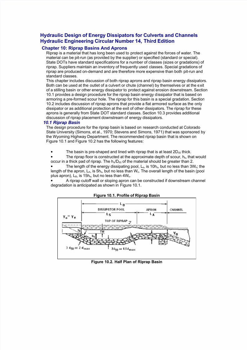
10.1 Riprap BasinThe design procedure for the riprap basin is based on research conducted at ColoradoState University (Simons, et al., 1970; Stevens and Simons, 1971) that was sponsored bythe Wyoming Highway Department. The recommended riprap basin that is shown onFigure 10.1 and Figure 10.2 has the following features:
• The basin is pre-shaped and lined with riprap that is at least 2D50 thick.
• The riprap floor is constructed at the approximate depth of scour, hs, that wouldoccur in a thick pad of riprap. The hs/D50 of the material should be greater than 2.
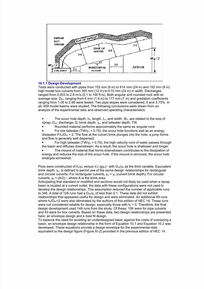
• The length of the energy dissipating pool, Ls, is 10hs, but no less than 3Wo; thelength of the apron, LA, is 5hs, but no less than Wo. The overall length of the basin (poolplus apron), LB, is 15hs, but no less than 4Wo.
• A riprap cutoff wall or sloping apron can be constructed if downstream channel
degradation is anticipated as shown in Figure 10.1.
Figure 10.1. Profile of Riprap Basin
Figure 10.2. Half Plan of Riprap Basin
8/3/2019 Hydraulic Design of Energy tors for Culverts and Channels
http://slidepdf.com/reader/full/hydraulic-design-of-energy-tors-for-culverts-and-channels 2/15
10.1.1 Design DevelopmentTests were conducted with pipes from 152 mm (6 in) to 914 mm (24 in) and 152 mm (6 in)high model box culverts from 305 mm (12 in) to 610 mm (24 in) in width. Dischargesranged from 0.003 to 2.8 m3/s (0.1 to 100 ft3/s). Both angular and rounded rock with anaverage size, D50, ranging from 6 mm (1.4 in) to 177 mm (7 in) and gradation coefficients
ranging from 1.05 to 2.66 were tested. Two pipe slopes were considered, 0 and 3.75%. Inall, 459 model basins were studied. The following conclusions were drawn from ananalysis of the experimental data and observed operating characteristics:
• The scour hole depth, hs; length, Ls; and width, Ws, are related to the size of riprap, D50; discharge, Q; brink depth, yo; and tailwater depth, TW.
• Rounded material performs approximately the same as angular rock.
• For low tailwater (TW/yo < 0.75), the scour hole functions well as an energydissipator if hs/D50 > 2. The flow at the culvert brink plunges into the hole, a jump formsand flow is generally well dispersed.
• For high tailwater (TW/yo > 0.75), the high velocity core of water passes throughthe basin and diffuses downstream. As a result, the scour hole is shallower and longer.
•
The mound of material that forms downstream contributes to the dissipation of energy and reduces the size of the scour hole. If the mound is removed, the scour holeenlarges somewhat.
Plots were constructed of hs/ye versus Vo/ (gye)1/2 with D50/ye as the third variable. Equivalentbrink depth, ye, is defined to permit use of the same design relationships for rectangular and circular culverts. For rectangular culverts, ye = yo (culvert brink depth). For circular culverts, ye = (A/2)1/2, where A is the brink area.Anticipating that standard or modified end sections would not likely be used when a riprapbasin is located at a culvert outlet, the data with these configurations were not used todevelop the design relationships. This assumption reduced the number of applicable runsto 346. A total of 128 runs had a D50/ye of less than 0.1. These data did not exhibitrelationships that appeared useful for design and were eliminated. An additional 69 runs
where hs/D50<2 were also eliminated by the authors of this edition of HEC 14. These runswere not considered reliable for design, especially those with hs = 0. Therefore, the finaldesign development used 149 runs from the study. Of these, 106 were for pipe culvertsand 43 were for box culverts. Based on these data, two design relationships are presentedhere: an envelope design and a best fit design.To balance the need for avoiding an underdesigned basin against the costs of oversizing abasin, an envelope design relationship in the form of Equation 10.1 and Equation 10.2 wasdeveloped. These equations provide a design envelope for the experimental dataequivalent to the design figure (Figure XI-2) provided in the previous edition of HEC 14
8/3/2019 Hydraulic Design of Energy tors for Culverts and Channels
http://slidepdf.com/reader/full/hydraulic-design-of-energy-tors-for-culverts-and-channels 3/15
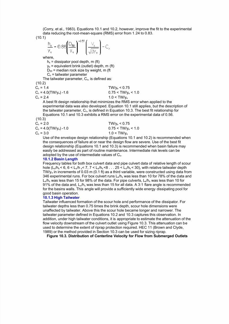
(Corry, et al., 1983). Equations 10.1 and 10.2, however, improve the fit to the experimentaldata reducing the root-mean-square (RMS) error from 1.24 to 0.83.
(10.1)
where,hs = dissipator pool depth, m (ft)ye = equivalent brink (outlet) depth, m (ft)D50 = median rock size by weight, m (ftCo = tailwater parameter
The tailwater parameter, Co, is defined as:(10.2)
Co = 1.4 TW/ye < 0.75
Co = 4.0(TW/ye) -1.6 0.75 < TW/ye < 1.0
Co = 2.4 1.0 < TW/ye
A best fit design relationship that minimizes the RMS error when applied to theexperimental data was also developed. Equation 10.1 still applies, but the description of the tailwater parameter, Co, is defined in Equation 10.3. The best fit relationship for
Equations 10.1 and 10.3 exhibits a RMS error on the experimental data of 0.56.(10.3)
Co = 2.0 TW/ye < 0.75
Co = 4.0(TW/ye) -1.0 0.75 < TW/ye < 1.0
Co = 3.0 1.0 < TW/ye
Use of the envelope design relationship (Equations 10.1 and 10.2) is recommended whenthe consequences of failure at or near the design flow are severe. Use of the best fitdesign relationship (Equations 10.1 and 10.3) is recommended when basin failure mayeasily be addressed as part of routine maintenance. Intermediate risk levels can beadopted by the use of intermediate values of Co.10.1.2 Basin LengthFrequency tables for both box culvert data and pipe culvert data of relative length of scour hole (Ls/hs < 6, 6 < Ls/h s< 7, 7 < Ls/hs <8 . . . 25 < Ls/hs < 30), with relative tailwater depthTW/ye in increments of 0.03 m (0.1 ft) as a third variable, were constructed using data from346 experimental runs. For box culvert runs Ls/hs was less than 10 for 78% of the data andLs/hs was less than 15 for 98% of the data. For pipe culverts, Ls/hs was less than 10 for 91% of the data and, Ls/hs was less than 15 for all data. A 3:1 flare angle is recommendedfor the basins walls. This angle will provide a sufficiently wide energy dissipating pool for good basin operation.10.1.3 High Tailwater Tailwater influenced formation of the scour hole and performance of the dissipator. For tailwater depths less than 0.75 times the brink depth, scour hole dimensions wereunaffected by tailwater. Above this the scour hole became longer and narrower. Thetailwater parameter defined in Equations 10.2 and 10.3 captures this observation. Inaddition, under high tailwater conditions, it is appropriate to estimate the attenuation of theflow velocity downstream of the culvert outlet using Figure 10.3. This attenuation can be
used to determine the extent of riprap protection required. HEC 11 (Brown and Clyde,1989) or the method provided in Section 10.3 can be used for sizing riprap.
Figure 10.3. Distribution of Centerline Velocity for Flow from Submerged Outlets

8/3/2019 Hydraulic Design of Energy tors for Culverts and Channels
http://slidepdf.com/reader/full/hydraulic-design-of-energy-tors-for-culverts-and-channels 4/15
10.1.4 Riprap DetailsBased on experience with conventional riprap design, the recommended thickness of riprap for the floor and sides of the basin is 2D50 or 1.50Dmax, where Dmax is the maximumsize of rock in the riprap mixture. Thickening of the riprap layer to 3D50 or 2Dmax on theforeslope of the roadway culvert outlet is warranted because of the severity of attack in thearea and the necessity for preventing undermining and consequent collapse of the culvert.Figure 10.1 illustrates these riprap details. The mixture of stone used for riprap and needfor a filter should meet the specifications described in HEC 11 (Brown and Clyde, 1989).10.1.5 Design ProcedureThe design procedure for a riprap basin is as follows:Step 1. Compute the culvert outlet velocity, Vo, and depth, yo.
For subcritical flow (culvert on mild or horizontal slope), use Figure 3.3 or Figure3.4 to obtain yo/D, then obtain Vo by dividing Q by the wetted area associated withyo. D is the height of a box culvert or diameter of a circular culvert.For supercritical flow (culvert on a steep slope), Vo will be the normal velocityobtained by using the Manning's Equation for appropriate slope, section, anddischarge.Compute the Froude number, Fr, for brink conditions using brink depth for boxculverts (ye=yo) and equivalent depth (ye = (A/2)1/2) for non-rectangular sections.
Step 2. Select D50 appropriate for locally available riprap. Determine Co from Equation 10.2or 10.3 and obtain hs/ye from Equation 10.1. Check to see that hs/D50≥ 2 and D50/ye≥ 0.1. If hs/D50 or D50/ye is out of this range, try a different riprap size. (Basins sized where hs/D50 isgreater than, but close to, 2 are often the most economical choice.)Step 3. Determine the length of the dissipation pool (scour hole), Ls, total basin length, LB,and basin width at the basin exit, WB, as shown in Figures 10.1 and 10.2. The walls andapron of the basin should be warped (or transitioned) so that the cross section of the basinat the exit conforms to the cross section of the natural channel. Abrupt transition of surfaces should be avoided to minimize separation zones and resultant eddies.Step 4. Determine the basin exit depth, yB = yc, and exit velocity, VB = Vc and compare withthe allowable exit velocity, Vallow. The allowable exit velocity may be taken as the estimatednormal velocity in the tailwater channel or a velocity specified based on stability criteria,whichever is larger. Critical depth at the basin exit may be determined iteratively usingEquation 7.14:
Q2/g = (Ac)3/Tc = [yc(WB + zyc)]3/ (WB + 2zyc) by trial and success to determine yB.

8/3/2019 Hydraulic Design of Energy tors for Culverts and Channels
http://slidepdf.com/reader/full/hydraulic-design-of-energy-tors-for-culverts-and-channels 5/15
Vc = Q/Ac
z = basin side slope, z:1 (H:V)If Vc≤ Vallow, the basin dimensions developed in step 3 are acceptable. However, itmay be possible to reduce the size of the dissipator pool and/or the apron with alarger riprap size. It may also be possible to maintain the dissipator pool, butreduce the flare on the apron to reduce the exit width to better fit the downstreamchannel. Steps 2 through 4 are repeated to evaluate alternative dissipator designs.
Step 5. Assess need for additional riprap downstream of the dissipator exit. If TW/yo≤0.75,no additional riprap is needed. With high tailwater (TW/yo≥ 0.75), estimate centerlinevelocity at a series of downstream cross sections using Figure 10.3 to determine the sizeand extent of additional protection. The riprap design details should be in accordance withspecifications in HEC 11 (Brown and Clyde, 1989) or similar highway departmentspecifications.Two design examples are provided. The first features a box culvert on a steep slope whilethe second shows a pipe culvert on a mild slope.Design Example: Riprap Basin (Culvert on a Steep Slope) (SI)Determine riprap basin dimensions using the envelope design (Equations 10.1 and 10.2)for a 2440 mm by 1830 mm reinforced concrete box (RCB) culvert that is in inlet controlwith supercritical flow in the culvert. Allowable exit velocity from the riprap basin, Vallow, is
2.1 m/s. Riprap is available with a D50 of 0.50, 0.55, and 0.75 m. Consider two tailwater conditions: 1) TW = 0.85 m and 2) TW = 1.28 m. Given:
• Q = 22.7 m3/s
• yo = 1.22 m (normal flow depth) = brink depth
SolutionStep 1. Compute the culvert outlet velocity, Vo, depth, yo, and Froude number for brinkconditions. For supercritical flow (culvert on a steep slope), Vo will be Vn
yo = ye = 1.22 mVo = Q/A = 22.7/ [1.22 (2.44)] = 7.63 m/sFr = Vo / (9.81ye)1/2 = 7.63/ [9.81(1.22)]1/2 = 2.21
Step 2. Select a trial D50 and obtain hs/ye from Equation 10.1. Check to see that hs/D50≥ 2and D50/ye≥ 0.1.
Try D50 = 0.55 m; D50/ye = 0.55/1.22 = 0.45 (≥ 0.1 OK)Two tailwater elevations are given; use the lowest to determine the basin size thatwill serve the tailwater range, that is, TW = 0.85 m.TW/ye = 0.85/1.22 = 0.7, which is less than 0.75. Therefore, from Equation 10.2,Co = 1.4From Equation 10.1,
hS = (hS /ye)ye = 1.55 (1.22) = 1.89 mhS/D50 = 1.89/0.55 = 3.4 and hS/D50≥ 2 is satisfied
Step 3. Size the basin as shown in Figures 10.1 and 10.2.LS = 10hS = 10(1.89) = 18.9 mLS min = 3Wo = 3(2.44) = 7.3 m, use LS = 18.9 mLB = 15hS = 15(1.89) = 28.4 mLB min = 4Wo = 4(2.44) = 9.8 m, use LB = 28.4 mWB = Wo + 2(LB/3) = 2.44 + 2(28.4/3) = 21.4 m
Step 4. Determine the basin exit depth, yB = yc, and exit velocity, VB = Vc.Q2/g = (Ac)3/Tc = [yc(WB + zyc)]3/ (WB + 2zyc)22.72/9.81 = 52.5 = [yc(21.4 + 2yc)]3/ (21.4 + 4yc)By trial and success, yc = 0.48 m, Tc = 23.3 m, Ac = 10.7 m2

8/3/2019 Hydraulic Design of Energy tors for Culverts and Channels
http://slidepdf.com/reader/full/hydraulic-design-of-energy-tors-for-culverts-and-channels 6/15
VB = Vc = Q/Ac = 22.7/10.7 = 2.1 m/s (acceptable)The initial trial of riprap (D50 = 0.55 m) results in a 28.4 m basin that satisfies alldesign requirements. Try the next larger riprap size to test if a smaller basin isfeasible by repeating steps 2 through 4.
Step 2 (2nd iteration). Select riprap size and compute basin depth.Try D50 = 0.75 m; D50/ye = 0.75/1.22 = 0.61 (≥ 0.1 OK)From Equation 10.1,
hS = (hS /ye)ye = 1.09 (1.22) = 1.34 mhS/D50 = 1.34/0.75 = 1.8 and hS/D50≥ 2 is not satisfied. Although not available, try ariprap size that will yield hS/D50 close to, but greater than, 2. (A basin sized for smaller riprap may be lined with larger riprap.) Repeat step 2.
Step 2 (3rd iteration). Select riprap size and compute basin depth.Try D50 = 0.71 m; D50/ye = 0.71/1.22 = 0.58 (≥ 0.1 OK)From Equation 10.1,
hS = (hS /ye)ye = 1.16 (1.22) = 1.42 mhS/D50 = 1.42/0.71 = 2.0 and hS/D50≥ 2 is satisfied.
Step 3 (3rd iteration). Size the basin as shown in Figures 10.1 and 10.2.LS = 10hS = 10(1.42) = 14.2 mLS min = 3Wo = 3(2.44) = 7.3 m, use LS = 14.2 mLB = 15hS = 15(1.42) = 21.3 mLB min = 4Wo = 4(2.44) = 9.8 m, use LB = 21.3 mWB = Wo + 2(LB/3) = 2.44 + 2(21.3/3) = 16.6 mHowever, since the trial D50 is not available, the next larger riprap size (D50 = 0.75m) would be used to line a basin with the given dimensions.
Step 4 (3rd iteration). Determine the basin exit depth, yB = yc, and exit velocity, VB = Vc.Q2/g = (Ac)3/Tc = [yc(WB + zyc)]3/ (WB + 2zyc)
22.72/9.81 = 52.5 = [yc(16.6 + 2yc)]3/ (16.6 + 4yc)By trial and success, yc = 0.56 m, Tc = 18.8 m, Ac = 9.9 m2
VB = Vc = Q/Ac = 22.7/9.9 = 2.3 m/s (greater than 2.1 m/s; not acceptable). If theapron were extended (with a continued flare) such that the total basin length was28.4 m, the velocity would be reduced to the allowable level.Two feasible options have been identified. First, a 1.89 m deep, 18.9 m long pool,with a 9.5 m apron using D50 = 0.55 m. Second, a 1.42 m deep, 14.2 m long pool,with a 14.2 m apron using D50 = 0.75 m. Because the overall length is the same,the first option is likely to be more economical.
Step 5. For the design discharge, determine if TW/yo ≤0.75.For the first tailwater condition, TW/yo = 0.85/1.22 = 0.70, which satisfies TW/yo ≤0.75. No additional riprap needed downstream.For the second tailwater condition, TW/yo = 1.28/1.22 = 1.05, which does not
satisfy TW/yo ≤ 0.75. To determine required riprap, estimate centerline velocity ata series of downstream cross sections using Figure 10.3.Compute equivalent circular diameter, De, for brink area:A = π De
2 /4 = (yo)(Wo) = (1.22)(2.44) = 3.00 m2
De = [3.00(4)/ π ]1/2 = 1.95 mRock size can be determined using the procedures in Section 10.3 (Equation10.6) or other suitable method. The computations are summarized below.

8/3/2019 Hydraulic Design of Energy tors for Culverts and Channels
http://slidepdf.com/reader/full/hydraulic-design-of-energy-tors-for-culverts-and-channels 7/15
Computation Summary for Design Example (SI)
L/De L (m) VL /Vo (Figure 10.3) VL (m/s) Rock Size D50 (m)
10 19.5 0.59 4.50 0.43
15 29.3 0.42 3.20 0.22
20 39.0 0.30 2.29 0.11
21 41.0 0.28 2.13 0.10
The calculations above continue until VL ≤ Vallow. Riprap should be at least the sizeshown. As a practical consideration, the channel can be lined with the same sizerock used for the basin. Protection must extend at least 41.0 m downstream fromthe culvert brink, which is 12.6 m beyond the basin exit. Riprap should be installedin accordance with details shown in HEC 11.
Design Example: Riprap Basin (Culvert on a Steep Slope) (CU)Determine riprap basin dimensions using the envelope design (Equations 10.1 and 10.2)for an 8 ft by 6 ft reinforced concrete box (RCB) culvert that is in inlet control withsupercritical flow in the culvert. Allowable exit velocity from the riprap basin, Vallow, is 7 ft/s.Riprap is available with a D50 of 1.67, 1.83, and 2.5 ft. Consider two tailwater conditions: 1)TW = 2.8 ft and 2) TW = 4.2 ft. Given:
• Q = 800 ft3/s
• yo = 4 ft (normal flow depth) = brink depth
SolutionStep 1. Compute the culvert outlet velocity, Vo, depth, yo, and Froude number for brinkconditions. For supercritical flow (culvert on a steep slope), Vo will be Vn.
yo = ye = 4 ftVo = Q/A = 800/ [4 (8)] = 25 ft/sFr = Vo / (32.2ye)1/2 = 25/ [32.2(4)]1/2 = 2.2
Step 2. Select a trial D50 and obtain hs/ye from Equation 10.1. Check to see that hs/D50 ≥ 2and D50/ye ≥ 0.1.
Try D50 = 1.83 ft; D50/ye = 1.83/4 = 0.46 (≥ 0.1 OK)
Two tailwater elevations are given; use the lowest to determine the basin size thatwill serve the tailwater range, that is, TW = 2.8 ft.TW/ye = 2.8/4 = 0.7, which is less than 0.75. From Equation 10.2, Co = 1.4From Equation 10.1,
hS = (hS /ye)ye = 1.50 (4) = 6.0 fthS/D50 = 6.0/1.83 = 3.3 and hS/D50≥ 2 is satisfied
Step 3. Size the basin as shown in Figures 10.1 and 10.2.LS = 10hS = 10(6.0) = 60 ftLS min = 3Wo = 3(8) = 24 ft, use LS = 60 ftLB = 15hS = 15(6.0) = 90 ftLB min = 4Wo = 4(8) = 32 ft, use LB = 90 ftWB = Wo + 2(LB/3) = 8 + 2(90/3) = 68 ft
Step 4. Determine the basin exit depth, yB = yc, and exit velocity, VB = Vc.Q2/g = (Ac)3/Tc = [yc(WB + zyc)]3/ (WB + 2zyc)8002/32.2 = 19,876 = [yc(68 + 2yc)]3/ (68 + 4yc)By trial and success, yc = 1.60 ft, Tc = 74.4 ft, Ac = 113.9 ft2
VB = Vc = Q/Ac = 800/113.9 = 7.0 ft/s (acceptable)
8/3/2019 Hydraulic Design of Energy tors for Culverts and Channels
http://slidepdf.com/reader/full/hydraulic-design-of-energy-tors-for-culverts-and-channels 8/15
The initial trial of riprap (D50 = 1.83 ft) results in a 90 ft basin that satisfies alldesign requirements. Try the next larger riprap size to test if a smaller basin isfeasible by repeating steps 2 through 4.
Step 2 (2nd iteration). Select riprap size and compute basin depth.Try D50 = 2.5 ft; D50/ye = 2.5/4 = 0.63 (≥ 0.1 OK)From Equation 10.1,
hs = (hs /ye)ye = 1.04 (4) = 4.2 fths/D50 = 4.2/2.5 = 1.7 and hS/D50≥ 2 is not satisfied. Although not available, try ariprap size that will yield hs/D50 close to, but greater than, 2. (A basin sized for smaller riprap may be lined with larger riprap.) Repeat step 2.
Step 2 (3rd iteration). Select riprap size and compute basin depth.Try D50 = 2.3 ft; D50/ye = 2.3/4 = 0.58 (≥ 0.1 OK)From Equation 10.1,
hs = (hs /ye)ye = 1.15 (4) = 4.6 fths/D50 = 4.6/2.3 = 2.0 and hs/D50≥ 2 is satisfied.
Step 3 (3rd iteration). Size the basin as shown in Figures 10.1 and 10.2.LS = 10hS = 10(4.6) = 46 ftLS min = 3Wo = 3(8) = 24 ft, use LS = 46 ftLB = 15hS = 15(4.6) = 69 ftLB min = 4Wo = 4(8) = 32 ft, use LB = 69 ftWB = Wo + 2(LB/3) = 8 + 2(69/3) = 54 ftHowever, since the trial D50 is not available, the next larger riprap size (D50 = 2.5 ft)would be used to line a basin with the given dimensions.
Step 4 (3rd iteration). Determine the basin exit depth, yB = yc, and exit velocity, VB = Vc.Q2/g = (Ac)3/Tc = [yc(WB + zyc)]3/ (WB + 2zyc)8002/32.2 = 19,876 = [yc(54 + 2yc)]3/ (54 + 4yc)
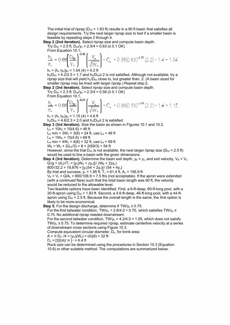
By trial and success, yc = 1.85 ft, Tc = 61.4 ft, Ac = 106.9 ft2
VB = Vc = Q/Ac = 800/106.9 = 7.5 ft/s (not acceptable). If the apron were extended(with a continued flare) such that the total basin length was 90 ft, the velocitywould be reduced to the allowable level.Two feasible options have been identified. First, a 6-ft-deep, 60-ft-long pool, with a30-ft-apron using D50 = 1.83 ft. Second, a 4.6-ft-deep, 46-ft-long pool, with a 44-ft-apron using D50 = 2.5 ft. Because the overall length is the same, the first option islikely to be more economical.
Step 5. For the design discharge, determine if TW/yo ≤ 0.75.For the first tailwater condition, TW/yo = 2.8/4.0 = 0.70, which satisfies TW/yo ≤0.75. No additional riprap needed downstream.For the second tailwater condition, TW/yo = 4.2/4.0 = 1.05, which does not satisfyTW/yo ≤ 0.75. To determine required riprap, estimate centerline velocity at a series
of downstream cross sections using Figure 10.3.Compute equivalent circular diameter, De, for brink area:A = π De
2 /4 = (yo)(Wo) = (4)(8) = 32 ft2
De = [32(4)/ π ]1/2 = 6.4 ftRock size can be determined using the procedures in Section 10.3 (Equation10.6) or other suitable method. The computations are summarized below.

8/3/2019 Hydraulic Design of Energy tors for Culverts and Channels
http://slidepdf.com/reader/full/hydraulic-design-of-energy-tors-for-culverts-and-channels 9/15
Computation Summary for Design Example (CU)
L/De L (ft) VL /Vo (Figure 10.3) VL (ft/s) Rock Size D50 (ft)
10 64 0.59 14.7 1.42
15 96 0.42 10.5 0.72
20 128 0.30 7.5 0.37
21 135 0.28 7.0 0.32
The calculations above continue until VL ≤ Vallow. Riprap should be at least the sizeshown. As a practical consideration, the channel can be lined with the same sizerock used for the basin. Protection must extend at least 135 ft downstream fromthe culvert brink, which is 45 ft beyond the basin exit. Riprap should be installed inaccordance with details shown in HEC 11.
Design Example: Riprap Basin (Culvert on a Mild Slope) (SI)Determine riprap basin dimensions using the envelope design (Equations 10.1 and 10.2)for a pipe culvert that is in outlet control with subcritical flow in the culvert. Allowable exitvelocity from the riprap basin, Vallow, is 2.1 m/s. Riprap is available with a D50 of 0.125,0.150, and 0.250 m. Given:
• D = 1.83 m CMP with Manning's n = 0.024• So = 0.004 m/m
• Q = 3.82 m3/s
• yn = 1.37 m (normal flow depth in the pipe)
• Vn = 1.80 m/s (normal velocity in the pipe)
• TW = 0.61 m (tailwater depth)
SolutionStep 1. Compute the culvert outlet velocity, Vo, and depth, yo.
For subcritical flow (culvert on mild slope), use Figure 3.4 to obtain yo/D, thencalculate Vo by dividing Q by the wetted area for yo.Ku Q/D2.5 = 1.81 (3.82)/1.832.5 = 1.53TW/D = 0.61/1.83 = 0.33From Figure 3.4, yo/D = 0.45yo = (yo/D)D = 0.45(1.83) = 0.823 m (brink depth)From Table B.2, for yo /D = 0.45, the brink area ratio A/D2 = 0.343A = (A/D2)D2 = 0.343(1.83)2 = 1.15 m2
Vo = Q/A = 3.82/1.15 = 3.32 m/sye = (A/2)1/2 = (1.15/2)1/2 = 0.76 mFr = Vo / [9.81(ye)]1/2 = 3.32/ [9.81(0.76)]1/2 = 1.22
Step 2. Select a trial D50 and obtain hs/ye from Equation 10.1. Check to see that hs/D50≥ 2and D50/ye≥ 0.1.
Try D50 = 0.15 m; D50/ye = 0.15/0.76 = 0.20 (≥ 0.1 OK)TW/ye = 0.61/0.76 = 0.80. Therefore, from Equation 10.2,Co = 4.0(TW/ye) -1.6 = 4.0(0.80) -1.6 = 1.61From Equation 10.1,
hS = (hS /ye)ye = 0.933 (0.76) = 0.71 mhS/D50 = 0.71/0.15 = 4.7 and hS/D50≥ 2 is satisfied
Step 3. Size the basin as shown in Figures 10.1 and 10.2.LS = 10hS = 10(0.71) = 7.1 mLS min = 3Wo = 3(1.83) = 5.5 m, use LS = 7.1 mLB = 15hS = 15(0.71) = 10.7 m

8/3/2019 Hydraulic Design of Energy tors for Culverts and Channels
http://slidepdf.com/reader/full/hydraulic-design-of-energy-tors-for-culverts-and-channels 10/15
LB min = 4Wo = 4(1.83) = 7.3 m, use LB = 10.7 mWB = Wo + 2(LB/3) = 1.83 + 2(10.7/3) = 9.0 m
Step 4. Determine the basin exit depth, yB = yc and exit velocity, VB = Vc.Q2/g = (Ac)3/Tc = [yc(WB + zyc)]3/ (WB + 2zyc)3.822/9.81 = 1.49 = [yc(9.0 + 2yc)]3/ (9.0 + 4yc)By trial and success, yc = 0.26 m, Tc =10.0 m, Ac = 2.48 m2
Vc = Q/Ac = 3.82/2.48 = 1.5 m/s (acceptable)The initial trial of riprap (D50 = 0.15 m) results in a 10.7 m basin that satisfies alldesign requirements. Try the next larger riprap size to test if a smaller basin isfeasible by repeating steps 2 through 4.
Step 2 (2nd iteration). Select a trial D50 and obtain hs/ye from Equation 10.1.Try D50 = 0.25 m; D50/ye = 0.25/0.76 = 0.33 (≥ 0.1 OK)From Equation 10.1,
hS = (hS /ye)ye = 0.320 (0.76) = 0.24 mhS/D50 = 0.24/0.25 = 0.96 and hS/D50≥ 2 is not satisfied. Although not available, trya riprap size that will yield hS/D50 close to, but greater than 2. (A basin sized for
smaller riprap may be lined with larger riprap.) Repeat step 2.Step 2 (3rd iteration). Select a trial D50 and obtain hs/ye from Equation 10.1.
Try D50 = 0.205 m; D50/ye = 0.205/0.76 = 0.27 (≥ 0.1 OK)From Equation 10.1,
hS = (hS /ye)ye = 0.545 (0.76) = 0.41 mhS/D50 = 0.41/0.205 = 2.0 and hS/D50≥ 2 is satisfied. Continue to step 3.
Step 3 (3rd iteration). Size the basin as shown in Figures 10.1 and 10.2.LS = 10hS = 10(0.41) = 4.1 mLS min = 3Wo = 3(1.83) = 5.5 m, use LS = 5.5 mLB = 15hS = 15(0.41) = 6.2 m
LB min = 4Wo = 4(1.83) = 7.3 m, use LB = 7.3 mWB = Wo + 2(LB/3) = 1.83 + 2(7.3/3) = 6.7 mHowever, since the trial D50 is not available, the next larger riprap size (D50 = 0.25m) would be used to line a basin with the given dimensions.
Step 4 (3rd iteration). Determine the basin exit depth, yB = yc and exit velocity, VB = Vc.Q2/g = (Ac)3/Tc = [yc(WB + zyc)]3/ (WB + 2zyc)3.822/9.81 = 1.49 = [yc(6.7 + 2yc)]3/ (6.7 + 4yc)By trial and success, yc = 0.31 m, Tc =7.94 m, Ac = 2.28 m2
Vc = Q/Ac = 3.82/2.28 = 1.7 m/s (acceptable)Two feasible options have been identified. First, a 0.71 m deep, 7.1 m long pool,with an 3.6 m apron using D50 = 0.15 m. Second, a 0.41 m deep, 5.5 m long pool,with a 1.8 m apron using D50 = 0.25 m. The choice between these two options willlikely depend on the available space and the cost of riprap.
Step 5. For the design discharge, determine if TW/yo ≤ 0.75TW/yo = 0.61/0.823 = 0.74, which satisfies TW/yo ≤ 0.75. No additional riprapneeded.
Design Example: Riprap Basin (Culvert on a Mild Slope) (CU)Determine riprap basin dimensions using the envelope design (Equations 10.1 and 10.2)for a pipe culvert that is in outlet control with subcritical flow in the culvert. Allowable exitvelocity from the riprap basin, Vallow, is 7.0 ft/s. Riprap is available with a D50 of 0.42, 0.50,and 0.83 ft. Given:

8/3/2019 Hydraulic Design of Energy tors for Culverts and Channels
http://slidepdf.com/reader/full/hydraulic-design-of-energy-tors-for-culverts-and-channels 11/15
• D = 6 ft CMP with Manning's n = 0.024
• So = 0.004 ft/ft
• Q = 135 ft3/s
• yn = 4.5 ft (normal flow depth in the pipe)
• Vn = 5.9 ft/s (normal velocity in the pipe)
• TW = 2.0 ft (tailwater depth)
SolutionStep 1. Compute the culvert outlet velocity, Vo, depth, yo and Froude number.
For subcritical flow (culvert on mild slope), use Figure 3.4 to obtain yo/D, thencalculate Vo by dividing Q by the wetted area for yo.KuQ/D2.5 = 1.0(135)/62.5 = 1.53TW/D = 2.0/6 = 0.33From Figure 3.4, yo/D = 0.45yo = (yo/D)D = 0.45(6) = 2.7 ft (brink depth)From Table B.2 for yo/D = 0.45, the brink area ratio A/D2 = 0.343A = (A/D2)D2 = 0.343(6)2= 12.35 ft2
Vo = Q/A = 135/12.35 = 10.9 ft/sye = (A/2)1/2 = (12.35/2)1/2 = 2.48 ft
Fr = Vo / [32.2(ye)]1/2
= 10.9/ [32.2(2.48)]1/2
= 1.22Step 2. Select a trial D50 and obtain hs/ye from Equation 10.1. Check to see that hs/D50≥ 2and D50/ye≥ 0.1.
Try D50 = 0.5 ft; D50/ye = 0.5/2.48 = 0.20 (≥ 0.1 OK)TW/ye = 2.0/2.48 = 0.806. Therefore, from Equation 10.2,Co = 4.0(TW/ye) -1.6 = 4.0(0.806) -1.6 = 1.62From Equation 10.1,
hS = (hS /ye)ye = 0.923 (2.48) = 2.3 fthS/D50 = 2.3/0.5 = 4.6 and hS/D50≥ 2 is satisfied
Step 3. Size the basin as shown in Figures 10.1 and 10.2.
LS = 10hS = 10(2.3) = 23 ftLS min = 3Wo = 3(6) = 18 ft, use LS = 23 ftLB = 15hS = 15(2.3) = 34.5 ftLB min = 4Wo = 4(6) = 24 ft, use LB = 34.5 ftWB = Wo + 2(LB/3) = 6 + 2(34.5/3) = 29 ft
Step 4. Determine the basin exit depth, yB = yc and exit velocity, VB = Vc.Q2/g = (Ac)3/Tc = [yc(WB + zyc)]3/ (WB + 2zyc)1352/32.2 = 566 = [yc(29 + 2yc)]3/ (29 + 4yc)By trial and success, yc = 0.86 ft, Tc =32.4 ft, Ac = 26.4 ft2
Vc = Q/Ac = 135/26.4 = 5.1 ft/s (acceptable)The initial trial of riprap (D50 = 0.5 ft) results in a 34.5 ft basin that satisfies alldesign requirements. Try the next larger riprap size to test if a smaller basin isfeasible by repeating steps 2 through 4.
Step 2 (2nd iteration). Select a trial D50 and obtain hs/ye from Equation 10.1.Try D50 = 0.83 ft; D50/ye = 0.83/2.48 = 0.33 (≥ 0.1 OK)From Equation 10.1,
hS = (hS /ye)ye = 0.311 (2.48) = 0.8 ft

8/3/2019 Hydraulic Design of Energy tors for Culverts and Channels
http://slidepdf.com/reader/full/hydraulic-design-of-energy-tors-for-culverts-and-channels 12/15
hS/D50 = 0.8/0.83 = 0.96 and hS/D50≥ 2 is not satisfied. Although not available, try ariprap size that will yield hS/D50 close to, but greater than 2. (A basin sized for smaller riprap may be lined with larger riprap.) Repeat step 2.
Step 2 (3rd iteration). Select a trial D50 and obtain hs/ye from Equation 10.1.Try D50 = 0.65 ft; D50/ye = 0.65/2.48 = 0.26 (≥ 0.1 OK)From Equation 10.1,
hS = (hS /ye)ye = 0.581 (2.48) = 1.4 fthS/D50 = 1.4/0.65 = 2.15 and hS/D50≥ 2 is satisfied. Continue to step 3.
Step 3 (3rd iteration). Size the basin as shown in Figures 10.1 and 10.2.LS = 10hS = 10(1.4) = 14 ftLS min = 3Wo = 3(6) = 18 ft, use LS = 18 ftLB = 15hS = 15(1.4) = 21 ftLB min = 4Wo = 4(6) = 24 ft, use LB = 24 ftWB = Wo + 2(LB/3) = 6 + 2(24/3) = 22 ftHowever, since the trial D50 is not available, the next larger riprap size (D50 = 0.83ft) would be used to line a basin with the given dimensions.
Step 4 (3rd iteration). Determine the basin exit depth, yB = yc and exit velocity, VB = Vc.Q2/g = (Ac)3/Tc = [yc(WB + zyc)]3/ (WB + 2zyc)1352/32.2 = 566 = [yc(22 + 2yc)]3/ (22 + 4yc)By trial and success, yc = 1.02 ft, Tc =26.1 ft, Ac = 24.5 ft2
Vc = Q/Ac = 135/24.5 = 5.5 ft/s (acceptable)Two feasible options have been identified. First, a 2.3-ft-deep, 23-ft-long pool, withan 11.5-ft-apron using D50 = 0.5 ft. Second, a 1.4-ft-deep, 18-ft-long pool, with a 6-ft-apron using D50 = 0.83 ft. The choice between these two options will likelydepend on the available space and the cost of riprap.
Step 5. For the design discharge, determine if TW/yo ≤0.75TW/yo = 2.0/2.7 = 0.74, which satisfies TW/yo ≤ 0.75. No additional riprap needed.
10.2 Riprap ApronThe most commonly used device for outlet protection, primarily for culverts 1500 mm (60
in) or smaller, is a riprap apron. An example schematic of an apron taken from the FederalLands Division of the Federal Highway Administration is shown in Figure 10.4.Figure 10.4. Placed Riprap at Culverts (Central Federal Lands Highway Division)
8/3/2019 Hydraulic Design of Energy tors for Culverts and Channels
http://slidepdf.com/reader/full/hydraulic-design-of-energy-tors-for-culverts-and-channels 13/15
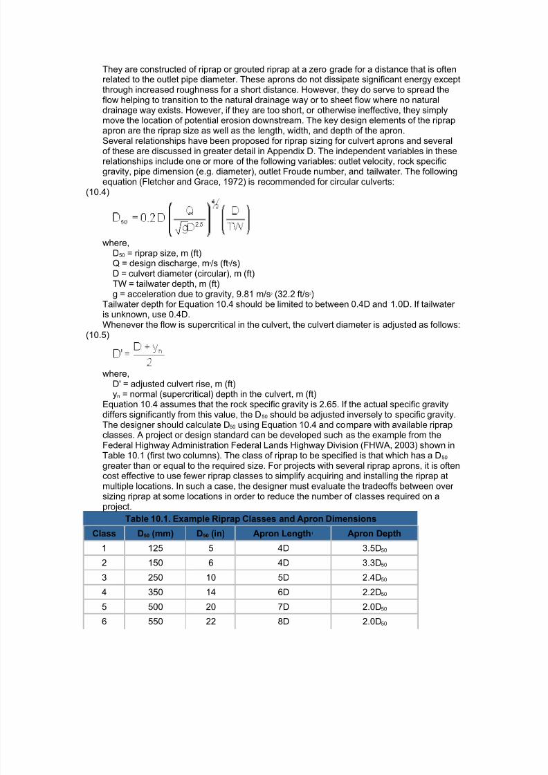
They are constructed of riprap or grouted riprap at a zero grade for a distance that is oftenrelated to the outlet pipe diameter. These aprons do not dissipate significant energy exceptthrough increased roughness for a short distance. However, they do serve to spread theflow helping to transition to the natural drainage way or to sheet flow where no naturaldrainage way exists. However, if they are too short, or otherwise ineffective, they simplymove the location of potential erosion downstream. The key design elements of the riprapapron are the riprap size as well as the length, width, and depth of the apron.Several relationships have been proposed for riprap sizing for culvert aprons and severalof these are discussed in greater detail in Appendix D. The independent variables in theserelationships include one or more of the following variables: outlet velocity, rock specificgravity, pipe dimension (e.g. diameter), outlet Froude number, and tailwater. The followingequation (Fletcher and Grace, 1972) is recommended for circular culverts:
(10.4)
where,D50 = riprap size, m (ft)Q = design discharge, m3/s (ft3/s)
D = culvert diameter (circular), m (ft)TW = tailwater depth, m (ft)g = acceleration due to gravity, 9.81 m/s2 (32.2 ft/s2)
Tailwater depth for Equation 10.4 should be limited to between 0.4D and 1.0D. If tailwater is unknown, use 0.4D.Whenever the flow is supercritical in the culvert, the culvert diameter is adjusted as follows:
(10.5)
where,D' = adjusted culvert rise, m (ft)yn = normal (supercritical) depth in the culvert, m (ft)
Equation 10.4 assumes that the rock specific gravity is 2.65. If the actual specific gravitydiffers significantly from this value, the D50 should be adjusted inversely to specific gravity.The designer should calculate D50 using Equation 10.4 and compare with available riprapclasses. A project or design standard can be developed such as the example from theFederal Highway Administration Federal Lands Highway Division (FHWA, 2003) shown inTable 10.1 (first two columns). The class of riprap to be specified is that which has a D50
greater than or equal to the required size. For projects with several riprap aprons, it is oftencost effective to use fewer riprap classes to simplify acquiring and installing the riprap atmultiple locations. In such a case, the designer must evaluate the tradeoffs between over sizing riprap at some locations in order to reduce the number of classes required on aproject.
Table 10.1. Example Riprap Classes and Apron Dimensions
Class D50 (mm) D50 (in) Apron Length1 Apron Depth
1 125 5 4D 3.5D50
2 150 6 4D 3.3D50
3 250 10 5D 2.4D50
4 350 14 6D 2.2D50
5 500 20 7D 2.0D50
6 550 22 8D 2.0D50

8/3/2019 Hydraulic Design of Energy tors for Culverts and Channels
http://slidepdf.com/reader/full/hydraulic-design-of-energy-tors-for-culverts-and-channels 14/15
8/3/2019 Hydraulic Design of Energy tors for Culverts and Channels
http://slidepdf.com/reader/full/hydraulic-design-of-energy-tors-for-culverts-and-channels 15/15
Step 2. Determine riprap class. From Table 10.1, riprap class 2 (D50 = 6 in) is required.Step 3. Estimate apron dimensions.
From Table 10.1 for riprap class 2,Length, L = 4D = 4(5) = 20 ftDepth = 3.3D50 = 3.3 (6) = 1.65 ftWidth (at apron end) = 3D + (2/3)L = 3(5) + (2/3)(20) = 28.3 ft
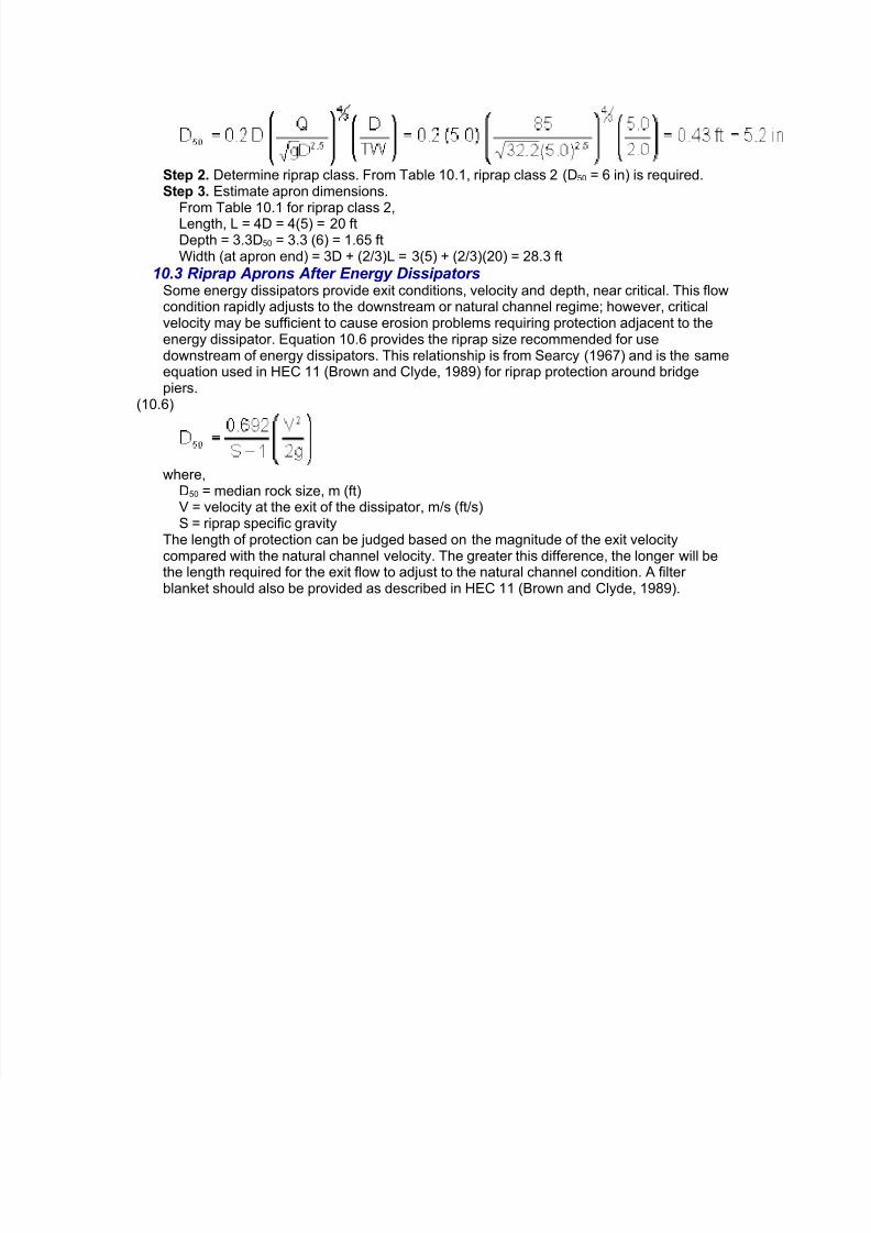
10.3 Riprap Aprons After Energy DissipatorsSome energy dissipators provide exit conditions, velocity and depth, near critical. This flowcondition rapidly adjusts to the downstream or natural channel regime; however, criticalvelocity may be sufficient to cause erosion problems requiring protection adjacent to theenergy dissipator. Equation 10.6 provides the riprap size recommended for usedownstream of energy dissipators. This relationship is from Searcy (1967) and is the sameequation used in HEC 11 (Brown and Clyde, 1989) for riprap protection around bridgepiers.
(10.6)
where,D50 = median rock size, m (ft)V = velocity at the exit of the dissipator, m/s (ft/s)S = riprap specific gravity
The length of protection can be judged based on the magnitude of the exit velocitycompared with the natural channel velocity. The greater this difference, the longer will bethe length required for the exit flow to adjust to the natural channel condition. A filter blanket should also be provided as described in HEC 11 (Brown and Clyde, 1989).