HydraStop™ Hydraulic Assist System Hydraulic Assist System Instructions Recommendations with...
3
Classic Performance Products, Inc. 714.522.2000 | fax 714.522.2500 378 E. Orangethorpe Ave. | Placentia, CA 92870 | www.classicperform.com Steering, Brake & Suspension Specialists Rev. 5/13/15 HydraStop™ Hydraulic Assist System Instructions Recommendations with the HydraStop system: Power steering filter: To protect the internal seals, valves, and other key features of the HydraStop, a filter will help capture contaminants that would otherwise shorten the life of the HydraStop, pump, and steering gear. Power steering pump: The pump will power both the HydraStop and the steering gear. Worn pumps can have problems trying to develop full pres- sure at idle speed. The old pump will have contaminants that will pollute the new brake booster. A clean quality pump is important. Steering gear: The old steering gear will have contaminants that will pol- lute the new HydraStop and possibly void warranty. Master cylinder: With the HydraStop, the master cylinder will develop much higher line pressure than before. A worn master cylinder may begin to leak at higher pressures. The leak may be external or internal. A quality master cylinder is important. Important pump requirements: The pump will need to flow at least 2 gallons per minute. Slower flow rates will cause the brake assist to be delayed and can loose steering assist while the brake is applied. The pump should make at least 1200psi. The total assist available is dependent on the max pressure from the pump. Instructions: 1. Disconnect the brake pedal linkage from the brake pedal. 2. Remove the original booster and/or master cylinder from the firewall. 3. The original hole in the firewall may need to be enlarged if using a flat steel bracket. If the large nut that holds the booster to the mounting bracket interferes with the firewall, the hole in the firewall will need to be enlarged to 2-1/8 inches. 4. Attach the new HydraStop and bracket to the firewall. Make sure the new brake pedal rod is aligned with the brake pedal as the rod goes thru the firewall. 5. Attach the brake pedal linkage to the brake pedal. Make sure the rod attaches to the pedal in the correct position. The rod should be close to the same center line as the vacuum booster. Make sure the pedal can move through its full range without binding. Some pedals have more than one position to connect the brake rod. Some installations require you drill a new hole to mount the pedal rod. Refer to the il- lustration as needed. (See Illustration 1) 6. Adjust the brake pedal rod so there is a small amount of free play between the HydraStop and the brake pedal. Never preload the Hydra- Stop with the brake pedal. Illustration 1 Continued on next page
Transcript of HydraStop™ Hydraulic Assist System Hydraulic Assist System Instructions Recommendations with...
Classic Performance Products, Inc. 714.522.2000 | fax 714.522.2500 378 E. Orangethorpe Ave. | Placentia, CA 92870 | www.classicperform.com
Steering, Brake & Suspension Specialists
Rev. 5/13/15
HydraStop™ Hydraulic Assist System InstructionsRecommendations with the HydraStop system:Power steering filter: To protect the internal seals, valves, and other key features of the HydraStop, a filter will help capture contaminants that would otherwise shorten the life of the HydraStop, pump, and steering gear.
Power steering pump: The pump will power both the HydraStop and the steering gear. Worn pumps can have problems trying to develop full pres-sure at idle speed. The old pump will have contaminants that will pollute the new brake booster. A clean quality pump is important.
Steering gear: The old steering gear will have contaminants that will pol-lute the new HydraStop and possibly void warranty.
Master cylinder: With the HydraStop, the master cylinder will develop much higher line pressure than before. A worn master cylinder may begin to leak at higher pressures. The leak may be external or internal. A quality master cylinder is important.
Important pump requirements:The pump will need to flow at least 2 gallons per minute. Slower flow rates will cause the brake assist to be delayed and can loose steering assist while the brake is applied. The pump should make at least 1200psi. The total assist available is dependent on the max pressure from the pump.
Instructions:1. Disconnect the brake pedal linkage from the brake pedal.
2. Remove the original booster and/or master cylinder from the firewall.
3. The original hole in the firewall may need to be enlarged if using a flat steel bracket. If the large nut that holds the booster to the mounting bracket interferes with the firewall, the hole in the firewall will need to be enlarged to 2-1/8 inches.
4. Attach the new HydraStop and bracket to the firewall. Make sure the new brake pedal rod is aligned with the brake pedal as the rod goes thru the firewall.
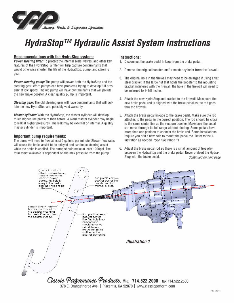
5. Attach the brake pedal linkage to the brake pedal. Make sure the rod attaches to the pedal in the correct position. The rod should be close to the same center line as the vacuum booster. Make sure the pedal can move through its full range without binding. Some pedals have more than one position to connect the brake rod. Some installations require you drill a new hole to mount the pedal rod. Refer to the il-lustration as needed. (See Illustration 1)
6. Adjust the brake pedal rod so there is a small amount of free play between the HydraStop and the brake pedal. Never preload the Hydra-Stop with the brake pedal.
Illustration 1
Continued on next page

Classic Performance Products, Inc. 714.522.2000 | fax 714.522.2500 378 E. Orangethorpe Ave. | Placentia, CA 92870 | www.classicperform.com
Steering, Brake & Suspension Specialists
nections are crossed the steering gear can violently turn the steering wheel; there is less chance of damage if the tires are on the ground. Fill the reservoir with new high quality power steering fluid. Fill the reservoir and install the cap. Start the engine and let it idle for 10-15 seconds. Stop the engine. Check the fluid level, add fluid as needed. Continue to run the engine for 10-15 seconds, and add fluid until the level remains the same (you do not need to add any more fluid at this time). Then, with the engine at idle begin to steer the vehicle to the ends of its travel. Stop the engine immediately if the pump starts to make noise, or if the steering effort starts to get heavier. Add more fluid and replace the cap on the reservoir. With the engine at idle, continue to steer the vehicle to the ends of its travel and add fluid as needed until the level remains the same (you do not need to add more fluid at this time). With the engine at idle apply the brakes several times. Stop the engine and apply the brakes several more times. Check the fluid level. Add more fluid as needed. Replace the cap, start the engine and apply the brakes several times. Stop the engine, apply the brakes several more times, and add fluid as needed until the fluid level remains the same (you do not need to add more fluid). Note: Lower quality fluids are more likely to foam, cause noises, and create steering pulses. A newly installed HydraStop may make some noise until all of the air trapped in the HydraStop has been expelled; this may take a few days of regular driving.
7. Connect the hoses. The pressure hose from the power steering pump will need to connect to the fitting closest to the accumulator. Refer to the illustration that identifies the different ports on the HydraStop. The other large fitting needs to be connected to the pressure going into the steering gear. Both return hoses are low pressure. If there are 2 return ports on the power steering reservoir connect the return hoses from both the booster and steering gear to the return ports on the reservoir. If the reservoir has 1 return port use the T-fitting or Y-fitting supplied with the hose kit. Refer to the illustrations showing the correct direc-tion of fluid flow thru the “Y” and “T” fittings. (See Illustration 2 & 3)
8. Install the master cylinder. Make sure the HydraStop push rod is cor-rect for the master cylinder. Never preload the master cylinder with the HydraStop. The booster rod should have a very small amount of free play to the master cylinder. Adjust the master cylinder and/or booster rod length as needed.
9. Bleed the brake system as necessary.
10. Fill and bleed the power steering system. It is recommended the tires are on the ground when the engine is started. If the steering hose con-
HydraStop™ Assist System Instructions (Continued)
Illustration 2
Continued on next page
Illustration 3

Classic Performance Products, Inc. 714.522.2000 | fax 714.522.2500 378 E. Orangethorpe Ave. | Placentia, CA 92870 | www.classicperform.com
Steering, Brake & Suspension Specialists
Technical tips:The brake release will be a little slower with the HydraStop. If the return line is blocked the brake release will be slower than normal. The HydraStop returns fluid as the brake is released.
There is an initial assist from the accumulator. As the assist pressure rises the pump will need to supply pressure to the HydraStop. If the brake feels slow to assist the pump flow rate may be too low.
If the steering assist falls off when the brake is applied the pump flow or pressure is too low. Typically this might happen at idle after the pump and fluid are warmed up from driving.
The pump does not maintain full pressure under normal driving. When there is no pressure on the steering wheel, or brake pedal, the valves in the HydraStop and steering gear will be open. The pump will always try to maintain its flow rate. As pressure is required from the steering gear or the HydraStop the flow rate will begin to drop. Initially the drop is very small, however as the pump nears maximum pressure the flow can sometimes decrease to almost 0. The pump will perform worse at idle speed while
HydraStop™ Assist System Instructions (Continued)
© Classic Performance Products, Inc. 2015All rights reserved. This document may not be reproduced without prior written permission of CPP.
1/4″ grade 5 10lb/ft 1/4″ grade 8 14lb/ft5/16″ grade 5 19lb/ft 5/16″ grade 8 29lb/ft3/8″ grade 5 33lb/ft 3/8″ grade 8 47lb/ft7/16″ grade 5 54lb/ft 7/16″ grade 8 78lb/ft1/2″ grade 5 78lb/ft 1/2″ grade 8 119lb/ft9/16″ grade 5 114lb/ft 9/16″ grade 8 169lb/ft5/8″ grade 5 154lb/ft 5/8″ grade 8 230lb/ft
GENERAL TORQUE SPECIFICATIONS:
NOTE: With 18” and larger wheels we recommend 1/2” wheel studs. The larger the wheel diameter, the greater the force is on the wheel studs. Please inquire about replace-ment wheel stud kits available from CPP.
steering and braking together, like when parking.
When the pump is maintaining a higher flow rate there will be a “static” pressure in the system. This pressure is caused by the resistance of fluid through the HydraStop and steering valves. This resistance causes the fluid and other components to heat up. Higher flow rates cause a higher “static” pressure. Higher pressure causes more drag on the engine. Lower flow rates cause less heat and less drag.
If the pump is turning too slowly it will not be able to make full pressure if needed. This is caused by an internal leakage within the pump. New pumps running at normal idle speeds should not have any problems. As the pump wears the internal leakage will increase. As the fluid gets warmer the viscosity will drop causing the leakage to increase. Underdriven pulley systems and slower idle speeds will slow the pump speed. This can also cause a problem. It is important the pump is not heavily worn, and use high quality power steering fluid.