ELECTRO HYDRAULIC POWER ASSIST STEERING DTC B1317, B1318
45
06–02–1 06 STEERING SECTION 06 Toc of SCT ON-BOARD DIAGNOSTIC . . . . 06-02 SYMPTOM TROUBLESHOOTING . . . . . 06-03 GENERAL PROCEDURES . . . 06-10 POWER STEERING . . . . . . . . . 06-14 TECHNICAL DATA . . . . . . . . . . 06-50 SERVICE TOOLS . . . . . . . . . . . 06-60 Toc of SCT 06–02 ON-BOARD DIAGNOSTIC ELECTRO HYDRAULIC POWER ASSIST STEERING (EHPAS) SYSTEM WIRING DIAGRAM . . . . . . . . . . . . . . . . . . . . . . . 06–02–1 ELECTRO HYDRAULIC POWER ASSIST STEERING (EHPAS) ON-BOARD DIAGNOSIS . . . . . . . . . . . . . . . . . . . . . . 06–02–2 DTC B1238 . . . . . . . . . . . . . . . . . . . . . . . 06–02–4 DTC B1317, B1318 . . . . . . . . . . . . . . . . . . 06–02–4 DTC B1342 . . . . . . . . . . . . . . . . . . . . . . . . 06–02–6 DTC B1352 . . . . . . . . . . . . . . . . . . . . . . . . 06–02–6 DTC B2477 . . . . . . . . . . . . . . . . . . . . . . . . 06–02–7 DTC C1099 . . . . . . . . . . . . . . . . . . . . . . . . 06–02–7 DTC C1278 . . . . . . . . . . . . . . . . . . . . . . . . 06–02–8 End of Toc ELECTRO HYDRAULIC POWER ASSIST STEERING (EHPAS) SYSTEM WIRING DIAGRAM DPE060200000W01 With ABS EHPAS 5 A EHPAS 80 A 1B 2F 3A 3B 3D A D C B 2D 1A 2B EHPAS WARNING LIGHT IG IG SW BATTERY CAN DRIVER CAN DRIVER CAN DRIVER EHPAS CONTROL MODULE STEERING ANGLE SENSOR INSTRUMENT CLUSTER DLC-2 PCM CAN_L CAN_H DPE602ZW1001
Transcript of ELECTRO HYDRAULIC POWER ASSIST STEERING DTC B1317, B1318

06–02–1
06STEERINGSECTION
06
Toc of SCTON-BOARD DIAGNOSTIC. . . . 06-02SYMPTOM
TROUBLESHOOTING . . . . . 06-03GENERAL PROCEDURES . . . 06-10
POWER STEERING . . . . . . . . . 06-14TECHNICAL DATA . . . . . . . . . . 06-50SERVICE TOOLS . . . . . . . . . . . 06-60
Toc of SCT06–02 ON-BOARD DIAGNOSTICELECTRO HYDRAULIC POWER ASSIST STEERING
(EHPAS) SYSTEM WIRING DIAGRAM . . . . . . . . . . . . . . . . . . . . . . . 06–02–1
ELECTRO HYDRAULIC POWER ASSIST STEERING (EHPAS) ON-BOARD DIAGNOSIS . . . . . . . . . . . . . . . . . . . . . . 06–02–2
DTC B1238 . . . . . . . . . . . . . . . . . . . . . . . 06–02–4
DTC B1317, B1318. . . . . . . . . . . . . . . . . . 06–02–4DTC B1342 . . . . . . . . . . . . . . . . . . . . . . . . 06–02–6DTC B1352 . . . . . . . . . . . . . . . . . . . . . . . . 06–02–6DTC B2477 . . . . . . . . . . . . . . . . . . . . . . . . 06–02–7DTC C1099 . . . . . . . . . . . . . . . . . . . . . . . . 06–02–7DTC C1278 . . . . . . . . . . . . . . . . . . . . . . . . 06–02–8
End of Toc
ELECTRO HYDRAULIC POWER ASSIST STEERING (EHPAS) SYSTEM WIRING DIAGRAMDPE060200000W01
With ABS
EHPAS 5 A
EHPAS 80 A 1B
2F
3A
3B
3D
A
D
C
B
2D
1A
2B
EHPAS WARNING LIGHT
IG
IG SW
BATTERY
CAN DRIVER
CAN DRIVER
CAN DRIVER
EHPAS CONTROL MODULE
STEERING ANGLE SENSOR
INSTRUMENT CLUSTER
DLC-2
PCM
CAN_L
CAN_H
DPE602ZW1001
v018898

06–02–2
ON-BOARD DIAGNOSTIC
With DSC
End Of SieELECTRO HYDRAULIC POWER ASSIST STEERING (EHPAS) ON-BOARD DIAGNOSIS
DPE060200000W02On-Board Diagnostic (OBD) Test Description• The OBD test inspects the integrity and function of the EHPAS and outputs the results when requested by the
specific tests.• On-board diagnostic test also:— Provides a quick inspection of the EHPAS usually performed at the start of each diagnostic procedure.— Provides verification after repairs to ensure that no other faults occurred during service.
• The OBD test is divided into 2 tests:— Read/clear diagnostic results, PID monitor and record.
Read/clear diagnostic results• This function allows reading or clearing of DTCs in the EHPAS control module memory.
PID/Data monitor and record• This function allows access of certain data values, input signals, calculated values, and system status
information.
Reading DTCs Procedure1. Connect the WDS or equivalent to the vehicle
DLC-2 connector.2. Retrieve DTCs using the WDS or equivalent.
Clearing DTCs Procedure1. After repairs have been made, perform the Reading DTCs Procedure.
1B
2F
2D
1A
2B
3B
3D
A
D
C
B
AB
AN
AE
AH
IG SW EHPAS 5 A
EHPAS 80 A
EHPAS WARNING LIGHT
BATTERY
CAN DRIVER
CAN DRIVER
CAN DRIVER
EHPAS CONTROL MODULE
STEERING ANGLE SENSOR
INSTRUMENT CLUSTER
DLC-2
CAN_L
CAN_H
PCM
DSC HU/CM
DPE602ZW1002
DLC-2
DPE402AW1005
v018898
With DSC End Of Sie 1B 2F 2D 1A 2B 3B 3D A D C B AB AN AE AH IG SW EHPAS 5 A EHPAS 80 A EHPAS WARNING LIGHT BATTERY CAN DRIVER CAN DRIVER CAN DRIVER EHPAS CONTROL MODULE STEERING ANGLE SENSOR INSTRUMENT CLUSTER DLC-2 CAN_L CAN_H PCM DSC HU/CM DPE602ZW1002
v018898
v018898

ON-BOARD DIAGNOSTIC
06–02–3
06
2. Clear DTCs using the WDS or equivalent.3. Verify that the customer’s concern has been resolved.
PID/Data Monitor and Record Procedure1. Connect the WDS or equivalent to the vehicle
DLC-2 connector.2. Access and monitor PIDs using the WDS or
equivalent.
DTC Table
PID/DATA Monitor Table
DLC-2
DPE402AW1005
DTCDiagnosis system component PageWDS or
equivalentB1238 EHPAS control module (See 06–02–4 DTC B1238.)B1317 Battery power supply (See 06–02–4 DTC B1317, B1318.)B1318 Battery power supply (See 06–02–4 DTC B1317, B1318.)B1342 EHPAS control module (See 06–02–6 DTC B1342.)B1352 Ignition power supply (See 06–02–6 DTC B1352.)B2477 EHPAS control module configuration (See 06–02–7 DTC B2477.)C1099 Electric power steering oil pump (motor) (See 06–02–7 DTC C1099.)C1278 Steering angle sensor (See 06–02–8 DTC C1278.)U0073 CAN bus communication error (See 09–02–1 MULTIPLEX COMMUNICATION
SYSTEM.)U0100 Lost communication with the PCM (See 09–02–1 MULTIPLEX COMMUNICATION
SYSTEM.)U2023 Fault received from other modules (See 09–02–1 MULTIPLEX COMMUNICATION
SYSTEM.)
PID Name(Definition)
Unit/Condition Condition/Specification Action EHPAS control
module terminalCCNT(Number of continuous codes)
— • DTCs are detected: 1—255• No DTCs are detected: 0
Perform inspection using appropriate DTC. —
ENGRPM(Engine speed signal) RPM • Engine speed 1,000 rpm:
1000 RPM
Inspect the PCM. (See 01–40B–10 PCM INSPECTION [MZR-CD (RF Turbo)].) (See 01–40A–7 PCM INSPECTION [L8, LF].)
—
MTR_AMP(Pump Motor Operation Current)
A • Indicates pump motor operation current.
Replace the EHPAS control module. (See 06-14–25 ELECTRIC POWER STEERING OIL PUMP REMOVAL/INSTALLATION [L8, LF].)
—
RPM_ACT(Actual pump motor revolution per minutes)
RPM • Indicates pump motor revolution per minutes.
Replace the EHPAS control module. (See 06-14–25 ELECTRIC POWER STEERING OIL PUMP REMOVAL/INSTALLATION [L8, LF].)
—

06–02–4
ON-BOARD DIAGNOSTIC
End Of SieDTC B1238
DPE060200000W03
Diagnostic procedure
End Of SieDTC B1317, B1318
DPE060200000W04
RPM_TGT(Target pump motor revolution per minutes)
RPM • Indicates pump motor target revolution per minutes.
Replace the EHPAS control module. (See 06-14–25 ELECTRIC POWER STEERING OIL PUMP REMOVAL/INSTALLATION [L8, LF].)
—
STEER_RATE(Steering wheel rotation rate)
°/s • Indicates steering wheel rotation rate.
Inspect steering angle sensor. (See 09–18–19 STEERING ANGLE SENSOR INSPECTION.)
3B, 3D
TEMP_BOARD(Printed circuit board temperature)
°C • Indicates circuit temperature.
Replace the EHPAS control module. (See 06-14–25 ELECTRIC POWER STEERING OIL PUMP REMOVAL/INSTALLATION [L8, LF].)
—
VPWR(Module supply voltage) V • IG switch ON: B+
Inspect the battery. (See 01–17B–2 BATTERY INSPECTION [MZR-CD (RF Turbo)].) (See 01–17A–5 BATTERY INSPECTION [L8, LF].)
1B, 2F
VSS(Vehicle speed) KPH/MPH
• Vehicle is stopped: 0 KPH/0 MPH
• Vehicle speed 20 km/h {12 mph}: 20 KPH/12 MPH
Inspect the PCM.(See 01–40B–10 PCM INSPECTION [MZR-CD (RF Turbo)].) (See 01–40A–7 PCM INSPECTION [L8, LF].) Inspect the instrument cluster. (See 09–22–3 INSTRUMENT CLUSTER INSPECTION.)
—
PID Name(Definition)
Unit/Condition Condition/Specification Action EHPAS control
module terminal
DTC B1238 Electro hydraulic power assist steering (EHPAS) control moduleDETECTION CONDITION • Excessive load to electric power steering oil pump
POSSIBLE CAUSE
• Due to the continuously static steering, being turned to the lock end, or other causes, the internal temperature of the electric power steering oil pump is more than the specified value.
STEP INSPECTION ACTION1 TURN IGNITION SWITCH OFF AND ALLOW ELECTRIC POWER STEERING OIL PUMP TO COOL DOWN.2 VERIFY THAT THE SAME DTC IS NOT
PRESENT• Turn the ignition switch to the ON position.• Clear the DTC from the memory.
(See 06–02–2 Clearing DTCs Procedure.)• Is the same DTC present?
Yes Replace the electric power steering oil pump, then go to the next step. (See 06-14–25 ELECTRIC POWER STEERING OIL PUMP REMOVAL/INSTALLATION [L8, LF].)
No Go to the next step.
3 VERIFY THAT NO OTHER DTCS ARE PRESENT• Are any other DTCs output?
Yes Go to the applicable DTC inspection.(See 06–02–3 DTC Table.)
No DTC troubleshooting completed.
DTC B1317, B1318 Battery power supplyDETECTION CONDITION • Low voltage or high voltage are detected at the voltage monitor.
POSSIBLE CAUSE
• Open or short circuit in wiring harness between electro hydraulic power assist steering (EHPAS) control module terminal 1B and battery positive terminal
• Battery and/or generator malfunction
v018898

ON-BOARD DIAGNOSTIC
06–02–5
06
Diagnostic procedure
End Of Sie
STEP INSPECTION ACTION1 INSPECT BATTERY VOLTAGE
• Is the battery terminal voltage normal?Yes Make sure that battery terminal connection is okay.
Go to the next step.No Charge or replace the battery, then go to Step 6.
2 INSPECT BATTERY GRAVITY• Is the battery specific gravity as specified?
Yes Go to the next step.No Replace the battery, then go to Step 6.
3 INSPECT CHARGING SYSTEM• Are the generator and drive belt tension
normal?
Yes Go to the next step.No Replace the generator and/or drive belt if necessary.
Go to step 6.4 INSPECT EHPAS CONTROL MODULE
POWER SUPPLY CIRCUIT FOR OPEN OR SHORT CIRCUIT• Start the engine.• Measure the voltage between following
EHPAS control module terminal (wiring harness-side) and ground.— EHPAS control module: 1B—ground
• Is the voltage 9 V or more?
Yes Go to the next Step.No Repair or replace the wiring harness for open circuit
between the EHPAS control module and ground, then go to Step 6.
5 INSPECT EHPAS CONTROL MODULE GROUND CIRCUIT FOR POOR GROUND OR OPEN CIRCUIT• Turn the ignition switch off.• Measure the resistance between the
following EHPAS control module terminal (wiring harness-side) and ground.— EHPAS control module: 1A—ground
• Is the resistance within 0—1 ohm?
Yes Go to the next step.No If there is no continuity:
• Repair or replace the wiring harness for open circuit between the EHPAS control module and ground, then go to the next step.
If the resistance is not within 0—1 ohm:• Repair or replace the wiring harness for poor ground,
then go to the next step.
6 VERIFY THAT THE SAME DTC IS NOT PRESENT • Make sure to reconnect all disconnected
connectors.• Clear the DTC from the memory.
(See 06–02–2 Clearing DTCs Procedure.)• Is the same DTC present?
Yes Replace the electric power steering oil pump, then go to the next step. (See 06-14–25 ELECTRIC POWER STEERING OIL PUMP REMOVAL/INSTALLATION [L8, LF].)
No Go to the next step.
7 VERIFY THAT NO OTHER DTCS ARE PRESENT• Are any other DTCs output?
Yes Go to the applicable DTC inspection.(See 06–02–3 DTC Table.)
No DTC troubleshooting completed.
1B
1A
1A
2A2E
2D
2C
2B2F1B3A
3D
3C
3B
BATTERY
EHPAS CONTROL MODULE
EHPAS 80 A FUSE
EHPAS CONTROL MODULE HARNESS-SIDE CONNECTOR
v018898

06–02–6
ON-BOARD DIAGNOSTIC
DTC B1342DPE060200000W05
Diagnostic procedure
End Of SieDTC B1352
DPE060200000W06
DTC B1342 Electro hydraulic power assist steering (EHPAS) control moduleDETECTION CONDITION • The EHPAS control module on-board diagnostic function detects system malfunction.
POSSIBLE CAUSE
• EHPAS control module internal malfunction• Poor connection at connectors
STEP INSPECTION ACTION1 VERIFY THAT THE SAME DTC IS NOT
PRESENT• Clear the DTC from the memory.
(See 06–02–2 Clearing DTCs Procedure.)• Is the same DTC present?
Yes Replace the electric power steering oil pump, then go to the next step. (See 06-14–25 ELECTRIC POWER STEERING OIL PUMP REMOVAL/INSTALLATION [L8, LF].)
No Go to the next step.2 VERIFY THAT NO OTHER DTCS ARE
PRESENT• Are any other DTCs output?
Yes Go to the applicable DTC inspection.(See 06–02–3 DTC Table.)
No DTC troubleshooting completed.
DTC B1352 Ignition power supplyDETECTION CONDITION
• Less than 2.5 V detected at the voltage monitor of the electro hydraulic power assist steering (EHPAS) control module
POSSIBLE CAUSE
• Short to ground in wiring harness between EHPAS control module terminal 2F and ignition switch• Open circuit in wiring harness between EHPAS control module terminal 2F and ignition switch• Poor connection at connectors
2F 1A
1A2A2E
2D2C
2B2F1B3A
3D
3C
3B
EHPAS 5 A FUSE
BATTERYEHPAS CONTROL MODULE
IGNITION SWITCH
EHPAS CONTROL MODULE HARNESS-SIDE CONNECTOR
v018898

ON-BOARD DIAGNOSTIC
06–02–7
06
Diagnostic procedure
End Of SieDTC B2477
DPE060200000W07
Diagnostic procedure
End Of SieDTC C1099
DPE060200000W08
STEP INSPECTION ACTION1 INSPECT FUSES
• Are the fuses normal?Yes Go to the next step.No Repair or replace the fuses, then go to the step 3.
2 INSPECT EHPAS CONTROL MODULE POWER SUPPLY CIRCUIT FOR OPEN OR SHORT CIRCUIT• Start the engine.• Measure the voltage between following
EHPAS control module terminal (wiring harness-side) and ground.— EHPAS control module: 2F—ground
• Is voltage 10 V or more?
Yes Go to the next step.No Repair or replace the harness for open circuit between
EHPAS control module and ground, then go to next step.
3 VERIFY THAT THE SAME DTC IS NOT PRESENT• Make sure to reconnect all disconnected
connectors.• Clear the DTC from the memory.
(See 06–02–2 Clearing DTCs Procedure.)• Is same DTC present?
Yes Replace the electric power steering oil pump, then go to the next step. (See 06-14–25 ELECTRIC POWER STEERING OIL PUMP REMOVAL/INSTALLATION [L8, LF].)
No Go to the next step.
4 VERIFY THAT NO OTHER DTCs ARE PRESENT• Are any other DTCs output?
Yes Go to the applicable DTC inspection.(See 06–02–3 DTC Table.)
No Troubleshooting completed.
DTC B2477 Electro hydraulic power assist steering (EHPAS) control module configuration
DETECTION CONDITION • Configuration setting failure is detected.
POSSIBLE CAUSE • Module configuration procedure was not completed properly.
STEP INSPECTION ACTION1 VERIFY CONFIGURATION
• Has the EHPAS control module configuration been performed?
Yes Go to the next step.No Perform configuration using the WDS or equivalent.
(See 06-14–27 ELECTRO HYDRAULIC POWER ASSIST STEERING (EHPAS) CONTROL MODULE CONFIGURATION.)
2 VERIFY THAT THE SAME DTC IS NOT PRESENT• Clear the DTC from the memory.
(See 06–02–2 Clearing DTCs Procedure.)• Is the same DTC present?
Yes Repeat the inspection from Step 1.If the malfunction recurs, replace the EHPAS control module.(See 06-14–25 ELECTRIC POWER STEERING OIL PUMP REMOVAL/INSTALLATION [L8, LF].)
No Go to the next step.3 VERIFY THAT NO OTHER DTCs ARE
PRESENT• Are any other DTCs output?
Yes Go to the applicable DTC inspection.(See 06–02–3 DTC Table.)
No DTC troubleshooting completed.
DTC C1099 Electric power steering oil pump (motor)DETECTION CONDITION
• The electro hydraulic power assist steering (EHPAS) control module detects that the motor speed is less than the specified value.
POSSIBLE CAUSE • Motor internal malfunction
v018898
v018898

06–02–8
ON-BOARD DIAGNOSTIC
Diagnostic procedure
End Of SieDTC C1278
DPE060200000W09
STEP INSPECTION ACTION1 REPLACE ELECTRIC POWER STEERING OIL PUMP
• Replace the electric power steering oil pump, then go to the next step. (See 06-14–25 ELECTRIC POWER STEERING OIL PUMP REMOVAL/INSTALLATION [L8, LF].)
2 VERIFY THAT NO OTHER DTCS ARE PRESENT• Are any other DTCs output?
Yes Go to the applicable DTC inspection.(See 06–02–3 DTC Table.)
No DTC troubleshooting completed.
DTC C1278 Steering angle sensor
DETECTION CONDITION
• The electro hydraulic power assist steering (EHPAS) control module detects that the monitor voltage from the steering angle sensor is more than 4.9 V or less than 0.8 V
• The EHPAS control module detects that the two monitor voltages modulate at the same phase a specified amount of phases or more.
• The EHPAS control module detects that the EHPAS sensor signal dose not change.
POSSIBLE CAUSE
• Short to power supply, open circuit, or short to ground in wiring harness between EHPAS control module terminal 3B and steering angle sensor B
• Short to power supply, open circuit, or short to ground in wiring harness between EHPAS control module terminal 3D and steering angle sensor terminal C
• Open circuit in wiring harness between EHPAS control module terminal 3A and steering angle sensor terminal D (with ABS)
• Open circuit in wiring harness between DSC HU/CM terminal AH and steering angle sensor terminal D (with DSC)
• Short circuit in wiring harness between steering angle sensor terminal A and D• Steering angle sensor malfunction.• Steering angle sensor ring has fallen off.
v018898
v018898
v018898
v018898

ON-BOARD DIAGNOSTIC
06–02–9
06
AB
AN
AE
AH
1A 2A2E2D2C
2B2F1B
3A
3D
3C
3B
3B
3D
A
D
C
BDSC HU/CM
3A
3B
3D
A
D
C
B
IGWITH ABS WITH DSC
ABCD
A AT
AUB
C
F I L O R U X AA AD AG AJ AM AP AS
E H K N Q T W Z AC AF AI AL AO ARD G J M P S V Y AB AE AH AK AN AQ
DSC HU/CM HARNESS-SIDE CONNECTOR
EHPAS CONTROL MODULE
STEERING ANGLE SENSOR
STEERING ANGLE SENSOR
STEERING ANGLE SENSOR HARNESS-SIDE CONNECTOR
EHPAS CONTROL MODULE
EHPAS CONTROL MODULE HARNESS-SIDE CONNECTOR
v018898
v018898
AB AN AE AH 3B 3D A D C B DSC HU/CM WITH DSC STEERING ANGLE SENSOR EHPAS CONTROL MODULE
v018898
v018898

06–02–10
ON-BOARD DIAGNOSTIC
Diagnostic procedureSTEP INSPECTION ACTION
1 INSPECT PID FOR STEERING ANGLE SENSOR MALFUNCTION USING WDS OR EQUIVALENT• Turn the ignition switch off.• Connect the WDS or equivalent to the DLC-
2.• Select the “STEER_RATE” PID.• Verify that the WDS display changes
correctly according to steering wheel operation.
• Does it change correctly?
Yes Go to the next step.No Replace the steering angle sensor.
(See 08–10–13 CLOCK SPRING REMOVAL/INSTALLATION.)
2 INSPECT POWER SUPPLY VOLTAGE OF STEERING ANGLE SENSOR• Turn the ignition switch to the ON position
(Engine off).• Measure the voltage between steering angle
sensor terminal A and ground.• Is the voltage B+?
Yes Go to the next step.No With ABS
• Repair or replace the wiring harness between ignition switch and steering angle sensor terminal A, then go to the step 7.
With DSC• Repair or replace the wiring harness between DSC HU/
CM terminal AB and steering angle sensor terminal A, then go to the step 7.
3 INSPECT GROUND CIRCUIT OF STEERING ANGLE SENSOR FOR OPEN CIRCUIT• Turn the ignition switch off.• Disconnect the EHPAS control module (with
ABS) or DSC HU/CM (with DSC) and steering angle sensor connectors.
• Inspect for continuity between EHPAS control module terminal 3A (with ABS) or DSC HU/CM terminal AH (with DSC) and steering angle sensor terminal D.
• Is there continuity?
Yes Go to the next step.No Repair or replace the wiring harness between EHPAS
control module terminal 3A (with ABS) or DSC HU/CM terminal AH (with DSC) and steering angle sensor terminal D, then go to the step 7.
4 INSPECT STEERING ANGLE SENSOR SIGNAL CIRCUIT FOR SHORT TO POWER• Turn ignition key to ON (engine OFF).• Measure the voltage between the EHPAS
control module and body ground at the following:— Sensor 1: EHPAS control module terminal
3B and body ground— Sensor 2: EHPAS control module terminal
3D and body ground• Is voltage B+?
Yes Repair or replace the related wiring harnesses between the EHPAS control module and steering angle sensor, then go to the step 7.
No Go to next step.
5 INSPECT STEERING ANGLE SENSOR SIGNAL CIRCUIT FOR SHORT TO GROUND• Turn the ignition switch off.• Inspect continuity between the EHPAS
control module and body ground at the following:— Sensor 1: EHPAS control module terminal
3B and body ground— Sensor 2: EHPAS control module terminal
3D and body ground• Is there continuity?
Yes Repair or replace the related wiring harnesses between the EHPAS control module and steering angle sensor, then go to the step 7.
No Go to the next step.
6 INSPECT SENSORS 1 AND 2 OF THE STEERING ANGLE SENSOR FOR CONTINUITY• Turn the ignition switch off.• Disconnect the EHPAS control module and
steering angle sensor connectors.• Inspect for continuity between steering angle
sensor terminals B and C.• Is there continuity?
Yes Replace the steering angle sensor, then go to the step 7. (See 08–10–13 CLOCK SPRING REMOVAL/INSTALLATION.)
No Go to the next step.
v018898
v018898
With DSC • Repair or replace the wiring harness between DSC HU/ CM terminal AB and steering angle sensor terminal A, then go to the step 7.
v018898
v018898
v018898
v018898
v018898
v018898
v018898

ON-BOARD DIAGNOSTIC
06–02–11
06
End Of Sie
7 VERIFY THAT THE SAME DTC IS NOT PRESENT• Reconnect all disconnected connectors.• Clear the DTC from the memory.
(See 06–02–2 Clearing DTCs Procedure.)• Is the same DTC present?
Yes • Repeat the inspection from Step 1.• If the malfunction recurs, replace the electric power
steering oil pump. (See 06-14–25 ELECTRIC POWER STEERING OIL PUMP REMOVAL/INSTALLATION [L8, LF].)
No Go to the next step.8 VERIFY THAT NO OTHER DTCS ARE
PRESENT• Are any other DTCs output?
Yes Go to the applicable DTC inspection.(See 06–02–3 DTC Table.)
No DTC troubleshooting completed.
STEP INSPECTION ACTION
v018898

SYMPTOM TROUBLESHOOTING
06–03–1
06
06–03 SYMPTOM TROUBLESHOOTINGELECTRO HYDRAULIC POWER ASSIST STEERING
(EHPAS) SYSTEM WIRING DIAGRAM . . . . . . . . . . . . . . . . . . . . . . . 06–03–1
FOREWORD . . . . . . . . . . . . . . . . . . . . . . 06–03–2
PRECAUTION. . . . . . . . . . . . . . . . . . . . . . 06–03–2SYMPTOM TROUBLESHOOTING. . . . . . 06–03–3NO.1 POOR POWER STEERING
ASSIST . . . . . . . . . . . . . . . . . . . . . . . . . . 06–03–3
End of Toc
ELECTRO HYDRAULIC POWER ASSIST STEERING (EHPAS) SYSTEM WIRING DIAGRAMDPE060300000W01
With ABS
EHPAS 5 A
EHPAS 80 A 1B
2F
3A
3B
3D
A
D
C
B
2D
1A
2B
EHPAS WARNING LIGHT
IG
IG SW
BATTERY
CAN DRIVER
CAN DRIVER
CAN DRIVER
EHPAS CONTROL MODULE
STEERING ANGLE SENSOR
INSTRUMENT CLUSTER
DLC-2
PCM
CAN_L
CAN_H
DPE602ZW1001
v018898

06–03–2
SYMPTOM TROUBLESHOOTING
With DSC
End Of SieFOREWORD
DPE060300000W02• Before performing the steps in Symptom Troubleshooting, perform the On-board Diagnostic Inspection. To
inspect the DTC, follow the DTC Inspection steps. (See 06–02–3 DTC Table.)End Of SiePRECAUTION
DPE060300000W03Intermittent Concern TroubleshootingVibration method• If a malfunction occurs or becomes worse while driving on a rough road or when the engine is vibrating,
perform the following steps.
Note• There are several reasons why vehicle or engine vibration could cause an electrical malfunction. Inspect
the following:— Connectors not fully seated.— Wiring harnesses not having full play.— Wires laying across brackets or moving parts.— Wires routed too close to hot parts.
• An improperly routed, improperly clamped, or loose wiring harness can cause wiring to become pinched between parts.
• The connector joints, points of vibration, and places where wiring harness pass through the firewall, body panels and other panels are the major areas to be inspected.
Inspection method for switch and/or sensor connectors or wires1. Connect the WDS or equivalent to the DLC-2.2. Turn the ignition switch to the ON position (engine off).
Note• If the engine starts and runs, perform the following steps at idle.
3. Access PIDs for the switch you are inspecting.4. Turn the switch on manually.
1B
2F
2D
1A
2B
3B
3D
A
D
C
B
AB
AN
AE
AH
IG SW EHPAS 5 A
EHPAS 80 A
EHPAS WARNING LIGHT
BATTERY
CAN DRIVER
CAN DRIVER
CAN DRIVER
EHPAS CONTROL MODULE
STEERING ANGLE SENSOR
INSTRUMENT CLUSTER
DLC-2
CAN_L
CAN_H
PCM
DSC HU/CM
DPE602ZW1002
v018898
With DSC End Of Sie 1B 2F 2D 1A 2B 3B 3D A D C B AB AN AE AH IG SW EHPAS 5 A EHPAS 80 A EHPAS WARNING LIGHT BATTERY CAN DRIVER CAN DRIVER CAN DRIVER EHPAS CONTROL MODULE STEERING ANGLE SENSOR INSTRUMENT CLUSTER DLC-2 CAN_L CAN_H PCM DSC HU/CM DPE602ZW1002
v018898
v018898

SYMPTOM TROUBLESHOOTING
06–03–3
06
5. Slightly shake each connector or wiring harness vertically and horizontally while monitoring the PID.• If the PID value is unstable, inspect for poor
connection.
Inspection method for sensors1. Connect the WDS or equivalent to the DLC-2.2. Turn the ignition switch to the ON position (engine off).
Note• If the engine starts and runs, perform the following steps at idle.
3. Access PIDs for the switch you are inspecting.4. Vibrate the sensor slightly with your finger.
• If the PID value is unstable or a malfunction occurs, inspect for poor connection and/or poorly mounted sensor.
Connector terminal inspection method1. Inspect the connection of each female terminal.2. Insert the male terminal to the female terminal
and inspect the female terminal for looseness.End Of Sie
SYMPTOM TROUBLESHOOTINGDPE060300000W04
• Verify the symptom, and perform troubleshooting according to the appropriate number.
End Of SieNO.1 POOR POWER STEERING ASSIST
DPE060300000W05
B3E0603W001
B3E0603W002
No. Symptom1 Poor power steering assist
1 POOR POWER STEERING ASSISTTROUBLESHOOTING HINTS• Power steering fluid leakage from electro hydraulic power assist steering (EHPAS) fluid line• Steering gear and linkage malfunction• EHPAS control module malfunction

06–03–4
SYMPTOM TROUBLESHOOTING
Diagnostic procedure
End Of Sie
STEP INSPECTION ACTION1 RETRIEVE DTC FROM EHPAS CONTROL
MODULE • Are any DTCs present?
Yes Record all DTC and go to the applicable DTC inspection.No Go to the next step.
2 INSPECT STEERING WHEEL ASSIST FUNCTION• Disconnect the EHPAS control module
connector (2-pin).• Is the power steering assist function
changed?
Yes Go to the next step.No Visually inspect the steering gear and linkage. Replace it if
the malfunction is found.
3 INSPECT IF THERE IS ANY FLUID LEAK FROM THE EHPAS FLUID LINE• Is there fluid leakage?
Yes Replace it if necessary.No Replace the EHPAS control module.
(See 06-14–25 ELECTRIC POWER STEERING OIL PUMP REMOVAL/INSTALLATION [L8, LF].)
v018898

GENERAL PROCEDURES
06–10–1
06
06–10 GENERAL PROCEDURESGENERAL PROCEDURES
(STEERING) . . . . . . . . . . . . . . . . . . . . . 06–10–1
End of Toc
GENERAL PROCEDURES (STEERING)DPE061000000W01
Wheel and Tire Installation1. When installing the wheels and tires, tighten the wheel nuts in a criss-cross pattern to the following tightening
torque.
Tightening torque88.2—117.6 N·m
{9.00—11.99kgf·m, 65.06—86.73 ft·lbf}
Connector Disconnection1. Disconnect the negative battery cable before performing any work that requires handling of connectors. (See
01–17B–1 BATTERY REMOVAL/INSTALLATION [MZR-CD (RF Turbo)].) (See 01–17A–1 BATTERY REMOVAL/INSTALLATION [L8, LF].)
Suspension Links Removal/Installation1. For the joint sections with rubber bushings, raise the vehicle using a lift, and then temporarily tighten the
installation bolts and nuts. Lower the vehicle to the ground and tighten them completely with the specified torque.
Power Steering Related Parts Installation1. If any power steering fluid line has been disconnected, perform the following after installation of the power
steering components. (See 06-14–4 AIR BLEEDING.) (See 06-14–4 POWER STEERING FLUID INSPECTION.) — Power steering fluid amount inspection— Power steering fluid leakage inspection— Air bleeding
Electro Hydraulic Power Assist Steering (EHPAS) Related Parts
Warning• If the configuration procedure is not completed, the EHPAS will not operate properly and it might
cause an unexpected accident. Therefore, when replacing or removing the electric power steering oil pump, make sure to perform the configuration procedure to ensure the proper EHPAS operation.
1. Make sure that there are no DTCs in the EHPAS memory after working on EHPAS related parts. If there are any codes in the memory, clear them.
2. When replacing or removing the electric power steering oil pump, perform the configuration procedures. (See 06-14–27 ELECTRO HYDRAULIC POWER ASSIST STEERING (EHPAS) CONTROL MODULE CONFIGURATION.)
End Of Sie
v018898
v018898

POWER STEERING
06-14–1
06
06-14 POWER STEERINGSTEERING LOCATION INDEX . . . . . . . . 06-14–1AIR BLEEDING . . . . . . . . . . . . . . . . . . . . 06-14–4POWER STEERING FLUID
INSPECTION . . . . . . . . . . . . . . . . . . . . . 06-14–4STEERING WHEEL AND COLUMN
INSPECTION . . . . . . . . . . . . . . . . . . . . . 06-14–7STEERING WHEEL AND COLUMN REMOVAL/
INSTALLATION . . . . . . . . . . . . . . . . . . . 06-14–7STEERING SHAFT INSPECTION. . . . . . 06-14–10STEERING GEAR AND LINKAGE REMOVAL/
INSTALLATION . . . . . . . . . . . . . . . . . . . 06-14–11STEERING GEAR AND LINKAGE
DISASSEMBLY . . . . . . . . . . . . . . . . . . . 06-14–12STEERING GEAR AND LINKAGE
INSPECTION . . . . . . . . . . . . . . . . . . . . . 06-14–15
STEERING GEAR AND LINKAGEASSEMBLY. . . . . . . . . . . . . . . . . . . . . . . 06-14–16
POWER STEERING OIL PUMP REMOVAL/INSTALLATION [MZR-CD(RF Turbo)] . . . . . . . . . . . . . . . . . . . . . . . 06-14–21
POWER STEERING OIL PUMP DISASSEMBLY/ASSEMBLY [MZR-CD (RF Turbo)] . . . . 06-14–22
ELECTRIC POWER STEERING OIL PUMP REMOVAL/INSTALLATION [L8, LF] . . . 06-14–25
ELECTRO HYDRAULIC POWER ASSIST STEERING (EHPAS) CONTROL MODULEINSPECTION . . . . . . . . . . . . . . . . . . . . . 06-14–26
ELECTRO HYDRAULIC POWER ASSIST STEERING (EHPAS) CONTROL MODULE CONFIGURATION . . . . . . . . . . . . . . . . . 06-14–27
End of Toc
STEERING LOCATION INDEXDPE061400000W01
L.H.D.
.
1
2
3
6
7
5
4
MZR-CD (RF Turbo)
L8, LF8
1
4
DPE614ZW1001
v018898
v018898
v018898
v018898
v018898
v018898
v018898
v018898
v018898
v002468
v002468
v002468
POWER STEERING OIL PUMP REMOVAL/ INSTALLATION [MZR-CD (RF Turbo)] . . . . . . . . . . . . . . . . . . . . . . . 06-14–21 POWER STEERING OIL PUMP DISASSEMBLY/ ASSEMBLY [MZR-CD (RF Turbo)] . . . . 06-14–22

06-14–2
POWER STEERING
1 Power steering fluid(See 06-14–4 AIR BLEEDING.)(See 06-14–4 POWER STEERING FLUID INSPECTION.)
2 Steering wheel and column(See 06-14–7 STEERING WHEEL AND COLUMN INSPECTION.)(See 06-14–7 STEERING WHEEL AND COLUMN REMOVAL/INSTALLATION.)
3 Steering shaft(See 06-14–10 STEERING SHAFT INSPECTION.)
4 Steering gear and linkage(See 06-14–11 STEERING GEAR AND LINKAGE REMOVAL/INSTALLATION.)(See 06-14–12 STEERING GEAR AND LINKAGE DISASSEMBLY.)(See 06-14–15 STEERING GEAR AND LINKAGE INSPECTION.)(See 06-14–16 STEERING GEAR AND LINKAGE ASSEMBLY.)
5 Power steering oil pump (MZR-CD (RF Turbo))(See 06-14–21 POWER STEERING OIL PUMP REMOVAL/INSTALLATION [MZR-CD (RF Turbo)].)(See 06-14–22 POWER STEERING OIL PUMP DISASSEMBLY/ASSEMBLY [MZR-CD (RF Turbo)].)
6 Electric power steering oil pump (L8, LF)(See 06-14–25 ELECTRIC POWER STEERING OIL PUMP REMOVAL/INSTALLATION [L8, LF].)
7 Electro hydraulic power assist steering (EHPAS) control module (L8, LF)(See 06-14–26 ELECTRO HYDRAULIC POWER ASSIST STEERING (EHPAS) CONTROL MODULE INSPECTION.)(See 06-14–27 ELECTRO HYDRAULIC POWER ASSIST STEERING (EHPAS) CONTROL MODULE CONFIGURATION.)
8 Steering angle sensor(See 08–10–13 CLOCK SPRING REMOVAL/INSTALLATION.)(See 09–18–19 STEERING ANGLE SENSOR INSPECTION.)
v018898
5 Power steering oil pump (MZR-CD (RF Turbo)) (See 06-14–21 POWER STEERING OIL PUMP REMOVAL/INSTALLATION [MZR-CD (RF Turbo)].) (See 06-14–22 POWER STEERING OIL PUMP DISASSEMBLY/ASSEMBLY [MZR-CD (RF Turbo)].) 6 Electric power steering oil pump (L8, LF)
v018898
v018898
v018898
v018898
v018898

POWER STEERING
06-14–3
06
R.H.D.
.
L8, LF
6
5
4
3
7
1
2
8
MZR-CD (RF Turbo)
1
4
DPE614ZW1002
1 Power steering fluid(See 06-14–4 AIR BLEEDING.)(See 06-14–4 POWER STEERING FLUID INSPECTION.)
2 Steering wheel and column(See 06-14–7 STEERING WHEEL AND COLUMN INSPECTION.)(See 06-14–7 STEERING WHEEL AND COLUMN REMOVAL/INSTALLATION.)
3 Steering shaft(See 06-14–10 STEERING SHAFT INSPECTION.)
4 Steering gear and linkage(See 06-14–11 STEERING GEAR AND LINKAGE REMOVAL/INSTALLATION.)(See 06-14–12 STEERING GEAR AND LINKAGE DISASSEMBLY.)(See 06-14–15 STEERING GEAR AND LINKAGE INSPECTION.)(See 06-14–16 STEERING GEAR AND LINKAGE ASSEMBLY.)
5 Power steering oil pump (MZR-CD (RF Turbo))(See 06-14–21 POWER STEERING OIL PUMP REMOVAL/INSTALLATION [MZR-CD (RF Turbo)].)(See 06-14–22 POWER STEERING OIL PUMP DISASSEMBLY/ASSEMBLY [MZR-CD (RF Turbo)].)
6 Electric power steering oil pump (L8, LF)(See 06-14–25 ELECTRIC POWER STEERING OIL PUMP REMOVAL/INSTALLATION [L8, LF].)
7 EHPAS control module (L8, LF)(See 06-14–26 ELECTRO HYDRAULIC POWER ASSIST STEERING (EHPAS) CONTROL MODULE INSPECTION.)(See 06-14–27 ELECTRO HYDRAULIC POWER ASSIST STEERING (EHPAS) CONTROL MODULE CONFIGURATION.)
8 Steering angle sensor(See 08–10–13 CLOCK SPRING REMOVAL/INSTALLATION.)(See 09–18–19 STEERING ANGLE SENSOR INSPECTION.)
v018898
06 R.H.D. L8, LF 6 5 4 3 7 1 2 8 MZR-CD (RF Turbo) 1 4 DPE614ZW1002
v018898
. 1 Power steering fluid (See 06-14–4 AIR BLEEDING.) (See 06-14–4 POWER STEERING FLUID INSPECTION.) 2 Steering wheel and column (See 06-14–7 STEERING WHEEL AND COLUMN INSPECTION.) (See 06-14–7 STEERING WHEEL AND COLUMN REMOVAL/INSTALLATION.) 3 Steering shaft (See 06-14–10 STEERING SHAFT INSPECTION.) 4 Steering gear and linkage (See 06-14–11 STEERING GEAR AND LINKAGE REMOVAL/INSTALLATION.) (See 06-14–12 STEERING GEAR AND LINKAGE DISASSEMBLY.) (See 06-14–15 STEERING GEAR AND LINKAGE INSPECTION.) (See 06-14–16 STEERING GEAR AND LINKAGE ASSEMBLY.) 5 Power steering oil pump (MZR-CD (RF Turbo)) (See 06-14–21 POWER STEERING OIL PUMP REMOVAL/INSTALLATION [MZR-CD (RF Turbo)].) (See 06-14–22 POWER STEERING OIL PUMP DISASSEMBLY/ASSEMBLY [MZR-CD (RF Turbo)].) 6 Electric power steering oil pump (L8, LF) (See 06-14–25 ELECTRIC POWER STEERING OIL PUMP REMOVAL/INSTALLATION [L8, LF].) 7 EHPAS control module (L8, LF) (See 06-14–26 ELECTRO HYDRAULIC POWER ASSIST STEERING (EHPAS) CONTROL MODULE INSPECTION.) (See 06-14–27 ELECTRO HYDRAULIC POWER ASSIST STEERING (EHPAS) CONTROL MODULE CONFIGURATION.) 8 Steering angle sensor (See 08–10–13 CLOCK SPRING REMOVAL/ INSTALLATION.) (See 09–18–19 STEERING ANGLE SENSOR INSPECTION.)
v018898
v018898
v018898
v018898

06-14–4
POWER STEERING
End Of SieAIR BLEEDING
DPE061400000W02
Caution• Do not maintain the steering wheel fully turned for 5 s or more. It is possible that oil temperature
can rise and this will negatively affect the oil pump.
1. Inspect the fluid level. (See 06-14–4 POWER STEERING FLUID INSPECTION.)2. Turn the steering wheel fully to the left and right several times.3. Reinspect the fluid level.
• If the fluid level has dropped, add fluid.4. Repeat Steps 2—3 until the fluid level stabilizes.5. Start the engine and let it idle.6. Turn the steering wheel fully to the left and right several times.7. Repeat Step 6 until the fluid is not foamy and the fluid level has not dropped.8. Inspect the fluid level, and If the fluid level has dropped, add fluid to a level between MAX and MIN of the
reserve tank.End Of SiePOWER STEERING FLUID INSPECTION
DPE061432040W01Fluid Level Inspection1. Verify that the fluid level is between MAX and MIN of the reserve tank when the engine is cold.
• If the fluid is not at the specified level, adjust the fluid level (MIN-MAX on reserve tank) by adding/draining the fluid.
Power steering fluid typeATF M-III or equivalent (e.g. Dexron ® II)
Power steering fluid capacity (approximate quantity)MZR-CD (RF Turbo): 0.97 L {1.03 US qt, 0.85 Imp qt}L8, LF: 0.8 L {0.85 US qt, 0.70 lmp qt}
Fluid Leakage Inspection1. Start the engine and idle it.2. Turn the steering wheel fully to left or right, to generate the fluid pressure.
Caution• Do not maintain the steering wheel fully turned for 5 s or more. It is possible that oil temperature
can rise and this will negatively affect the oil pump.
v018898
v018898

POWER STEERING
06-14–5
06
3. Inspect for the fluid leakage at the points indicated in the figure.
• If fluid leakage is found, repair the related parts.
Fluid pressure Inspection1. Set the SSTs so that the valve of the SST faces
toward the gear housing side as shown in the figure.
L.H.D. MZR-CD (RF Turbo)L.H.D. L8, LF
R.H.D. L8, LF R.H.D. MZR-CD (RF Turbo)
DPE614ZW1003
49 1232 670B
49 H002 671
A6E0612W101
v018898
v018898
R.H.D. L8, LF R.H.D. MZR-CD (RF Turbo)
v018898
L.H.D. MZR-CD (RF Turbo)
v018898
v018898
v018898
v018898

06-14–6
POWER STEERING
2. Disconnect the oil pump side joint of the pressure hose, connect the SSTs set in the Step 1.
Tightening torque29.4—44.1 N·m {3.00—4.49 kgf·m, 21.6—32.5
ft·lbf}
3. Bleed the air from the system.4. Open the gauge valve fully.5. Start the engine, turn the steering wheel to the left
and right to raise the power steering fluid to the appropriate temperature (50—60 °C {122—140 °F}).
6. Close the gauge valve completely.7. Increase the engine speed to 1,000—1,500 rpm
and measure the fluid pressure generated at the oil pump.• If it is less than the specification, repair or
replace the oil pump component. (MZR-CD (RF Turbo))
• If it is less than the specification, replace the oil pump as a single unit. (L8, LF)
Caution• Do not maintain the gauge valve fully
closed for 5 s or more. It is possible that oil temperature can rise and this will negatively affect the oil pump.
Oil pump fluid pressure (oil temperature 50—60 °C {122—140 °F}) MZR-CD (RF Turbo): 10.50—10.99 MPa {107.1—112.0 kgf/cm2, 1,523—1,593 psi} L8, LF: 10.4—11.0 MPa {107—112 kgf/cm2, 1,509—1,595 psi}
8. Open the gauge valve fully and increase the engine speed to 1,000—1,500 rpm.
9. Turn the steering wheel fully to the left and right, then measure the fluid pressure generated at the gear housing.
Caution• Do not maintain the steering wheel fully
turned for 5 s or more. It is possible that oil temperature can rise and this will negatively affect the oil pump.
Note• If the fluid pressure is less than the
specification, it is possible that the oil pump or gear housing is not operating correctly.
Gear housing fluid pressure (oil temperature 50—60 °C {122—140 °F})MZR-CD (RF Turbo): 10.50—10.99 MPa {107.1—112.0 kgf/cm2, 1,523—1,593 psi}L8, LF: 9.0—11.0 MPa {92—111 kgf/cm2, 1,306—1,585 psi}
10. After removing the SSTs, tighten the oil pump side joint of the pressure hose to the specified torque.
L8, LF
MZR-CD (RF Turbo)
49 G032 3A4A
49 G032 3A4A
DPE614ZW1004
FLUID TEMPERATURE50—60{122—140
°°F}
GAUGE
CLOSE VALVE COMPLETELY.
B3E0614W024
FLUID TEMPERATURE50—60
°
GAUGE
OPEN VALVE COMPLETELY.
{122—140 °F}
B3E0614W025
v018898
MZR-CD (RF Turbo) 49 G032 3A4A
v018898
v018898
v018898
v018898
v018898
v018898
v018898
v018898
v018898
v018898
v018898

POWER STEERING
06-14–7
06
Tightening torque29.4—44.1 N·m {3.00—4.49 kgf·m, 21.6—32.5 ft·lbf}
11. Bleed the air from the system.End Of SieSTEERING WHEEL AND COLUMN INSPECTION
DPE061432010W01Play Inspection1. With the wheels in the straight-ahead position, start the engine.2. Turn the steering wheel to the left and right gently, then verify that the steering wheel play is within the
specification.
Steering wheel play0—30 mm {0—1.18 in} (When hydraulic operating)
Looseness, Excessive Play Inspection1. Inspect the steering wheel for looseness or
excessive play in the axial direction of the shaft and four locations around the steering wheel.• If there is any malfunction, inspect the
following, and repair or replace the applicable part.— Column bearing wear— Looseness of the steering wheel
installation part— Looseness of the column installation area— Excessive play of the steering shaft joint— Excessive play of the steering gear
Steering Force Inspection1. Verify that the equipped tire size and tire air pressure is as specified.2. With the vehicle on a hard, level surface, put the wheels in the straight-ahead position.3. Remove the air bag module. (See 08–10–5 DRIVER-SIDE AIR BAG MODULE REMOVAL/INSTALLATION.)
Warning• Handling the air bag module improperly can accidentally operate (deploy) the air bag module,
which may seriously injure you. Read the service warnings before handling the air bag module. (See 08–10–2 SERVICE WARNINGS.) (See 08–10–4 SERVICE CAUTIONS.)
4. Start the engine and idle it.5. Verify that the EHPAS warning light does not illuminate. (L8, LF)6. Inspect the steering force using a torque wrench.
• If not within the specification, verify the following:— No air in steering system— No fluid leakage at hose or connectors— Function of oil pump and steering gear
Steering wheel force (reference value)7.8 N·m {80 kgf·cm, 69 in·lbf} or less
Note• Comparing another vehicle of the same
model under the same conditions is an acceptable inspection method.
• The steering force varies with conditions indicated below.— Road conditions: Such as dry, wet, asphalt, or concrete— Tire condition: such as brand, wear, and tire pressure
End Of SieSTEERING WHEEL AND COLUMN REMOVAL/INSTALLATION
DPE061432010W02
Warning• Handling the air bag module improperly can accidentally operate (deploy) the air bag module,
which may seriously injure you. Read the service warnings before handling the air bag module.
A6E0612W015
A6E0612W016

06-14–8
POWER STEERING
(See 08–10–2 SERVICE WARNINGS.) (See 08–10–4 SERVICE CAUTIONS.)
1. Remove the front scuff plate inner (driver’s side). (See 09–17–19 FRONT SCUFF PLATE REMOVAL/INSTALLATION.)
2. Remove the front side trim (driver’s side). (See 09–17–15 FRONT SIDE TRIM REMOVAL/INSTALLATION.)3. Remove the side wall. (See 09–17–11 SIDE WALL REMOVAL/INSTALLATION.)4. Remove the front console. (See 09–17–13 FRONT CONSOLE REMOVAL/INSTALLATION.)5. Remove the bonnet release lever. (See 09–14–5 BONNET LATCH AND RELEASE LEVER REMOVAL/
INSTALLATION.)6. Remove the lower panel. (See 09–17–8 LOWER PANEL REMOVAL/INSTALLATION.)7. Remove the meter hood. (See 09–17–7 METER HOOD REMOVAL/INSTALLATION.)8. Remove the instrument cluster. (See 09–22–1 INSTRUMENT CLUSTER REMOVAL/INSTALLATION.)9. Remove in the order indicated in the table.
10. Install in the reverse order of removal.11. If the steering lock component of a vehicle equipped with the advanced keyless system is replaced, perform the
following procedure after installation.• Without immobilizer system— Steering lock unit programming (See 09–14–21 STEERING LOCK UNIT ID CODE REGISTRATION.)
• With immobilizer system— Immobilizer system resetting (See 09–14–29 IMMOBILIZER SYSTEM COMPONENT
REPLACEMENT/KEY ADDITION AND CLEARING [WITH ADVANCED KEYLESS SYSTEM].)
.
7
5
4 3
6
1
B
B
A
A
2R
R
9
10
11
R
8
40.3—54.7 {4.11—5.57,29.7—40.3}
8.9—12.7 N·m {90—130 kgf·cm, 79—112 in·lbf}
15.7—22.5 {1.60—2.29,11.6—16.5}
N·m {kgf·m, ft·lbf}
17.6—26.5 {1.8—2.7,13.0—19.5}
DPE614ZW1005
1 Air bag module(See 08–10–5 DRIVER-SIDE AIR BAG MODULE REMOVAL/INSTALLATION.)
2 Lockbolt3 Steering wheel
(See 06-14–9 Steering Wheel Removal Note.)(See 06-14–10 Steering Wheel Installation Note.)
4 Column cover(See 09–17–7 COLUMN COVER REMOVAL/INSTALLATION.)
5 Clock spring(See 08–10–13 CLOCK SPRING REMOVAL/INSTALLATION.)

POWER STEERING
06-14–9
06
Steering Wheel Removal Note
Caution• Do not try to remove the steering wheel by hitting the shaft with a hammer. The column will be
damaged.
1. Set the wheels in the straight-ahead position.2. Remove the steering wheel using any commercially available puller.
Outer Cylinder Removal Note1. Remove the coil antenna. (With immobilizer system) (See 09–14–28 COIL ANTENNA REMOVAL/
INSTALLATION [ADVANCED KEYLESS SYSTEM].) (See 09–14–6 COIL ANTENNA REMOVAL/INSTALLATION [KEYLESS ENTRY SYSTEM].)
2. Insert the key into the key cylinder and turn it to the ACC position.3. Insert a pin from the position indicated by the
arrow in the figure, and while pressing the lock bar with the pin, remove the key cylinder from the steering lock component.
Steering Lock Component Removal Note1. Remove the bolt using a flathead screwdriver, and then remove the steering lock component.
6 Combination switch(See 09–18–18 COMBINATION SWITCH REMOVAL/INSTALLATION.)
7 Dust cover8 Steering shaft
(See 06-14–10 Steering Shaft Installation Note.)9 Outer cylinder
(See 06-14–9 Outer Cylinder Removal Note.)10 Ignition switch
(See 09–21–1 IGNITION SWITCH REMOVAL/INSTALLATION.)
11 Steering lock component(See 06-14–9 Steering Lock Component Removal Note.)(See 06-14–10 Steering Lock component Installation Note.)
LOCK BAR
LOCK BAR
WITHOUT IMMOBILIZER SYSTEM
WITH IMMOBILIZER SYSTEM
DPE614ZW1006

06-14–10
POWER STEERING
2. Make a groove in the heads of the steering lock mounting bolts using a chisel and hammer.
3. Remove the steering lock component.
Steering Lock component Installation Note1. Install the steering lock component to the steering shaft.2. Verify that the lock operates correctly.3. Install new steering lock mounting bolts.4. Tighten the bolts until the heads break off.
Steering Shaft Installation Note1. Verify that the tilt / telescope lever is in the LOCK position.2. Tighten the bolts in alphabetical order.
Steering Wheel Installation Note1. Set the wheels in the straight-ahead position and install the steering wheel.
End Of SieSTEERING SHAFT INSPECTION
DPE061432100W011. Inspect the column bearing for excessive play and damage.
B3A0614W011
B3A0614W010
A
B
C
B3E0614W007

POWER STEERING
06-14–11
06
2. Verify that the measurement of the steering shaft indicated in the figure is as specified.• If not within the specification replace the
steering shaft component.
Steering shaft length335.8—340.8 mm {13.23—13.41 in}
3. Inspect the tilt/telescope mechanism operation for the following.(1) Tilt/telescope lever moves smoothly from the
lock to the unlock position.(2) Steering shaft is fixed firmly when the tilt/
telescope lever is locked.• If there is any malfunction, replace the
steering shaft.End Of Sie
STEERING GEAR AND LINKAGE REMOVAL/INSTALLATIONDPE061432960W01
Caution• Performing the following procedures without first removing the ABS wheel-speed sensor may
possibly cause an open circuit in the wiring harness if it is pulled by mistake. Before performing the following procedures, disconnect the ABS wheel-speed sensor connector (axle side) and fix the wiring harness to an appropriate place where it will not be pulled by mistake while servicing the vehicle.
1. Remove the front crossmember, lower arm, front stabilizer, and steering gear and linkage as a single unit. (See 02–13–11 FRONT CROSSMEMBER REMOVAL/INSTALLATION.)
2. Remove the front stabilizer. (See 02–13–8 FRONT STABILIZER REMOVAL/INSTALLATION.)3. Remove in the order indicated in the table.4. Install in the reverse order of removal.
STEERING SHAFT LENGTH
DPE614ZW1007
TILT/TELESCOPE LEVER
UNLOCK
LOCK
DPE614ZW1008

06-14–12
POWER STEERING
5. After installation, inspect the front wheel alignment and adjust it if necessary. (See 02–11–2 FRONT WHEEL ALIGNMENT.).
End Of SieSTEERING GEAR AND LINKAGE DISASSEMBLY
DPE061432960W02
Caution• Place copper plates, rag, or similar material in a vise, when securing the mounting bracket portion
of the steering gear.
2
1
7.8—10.8 N·m{80—110 kgf·cm, 69.1—95.5 in·lbf}
7.8—10.8 N·m{80—110 kgf·cm, 69.1—95.5 in·lbf}
7.8—10.8 N·m{80—110 kgf·cm, 69.1—95.5 in·lbf}
74.4—104.8{7.59—10.68,54.88—79.29}
74.4—104.8{7.59—10.68,54.88—79.29}
74.4—104.8{7.59—10.68,54.88—79.29}
2
1
A
B
A
B
R.H.D.
L.H.D.
N·m {kgf·m, ft·lbf}
DPE614ZW1009
1 Insulator 2 Steering gear and linkage
v018898
v018898
v019625

POWER STEERING
06-14–13
06
1. Disassemble in the order indicated in the table..
8
76
43
2
9
18
17
16
14
15
13
12
10
11
19
23
22
22
20
21
5
1
SSTSST
SST
SST
SST
SST
DPE614ZW1010
1 Floor seal2 Oil pipe3 Tie-rod end
(See 06-14–14 Tie-rod End Disassembly Note.)4 Locknut5 Boot clamp6 Boot band7 Boot8 Tie rod
(See 06-14–14 Tie Rod Disassembly Note.)9 Locknut (on adjusting cover)
(See 06-14–14 Locknut (on Adjusting Cover), Adjusting Cover Disassembly Note.)
10 Adjusting cover(See 06-14–14 Locknut (on Adjusting Cover), Adjusting Cover Disassembly Note.)
11 Yoke spring12 Support yoke13 Housing cover14 Locknut (on pinion shaft)15 Pinion shaft and valve housing component16 Return pipe17 Clip18 Stopper19 Steering rack20 Rack bushing21 Oil seal
(See 06-14–14 Oil Seal Disassembly Note.)

06-14–14
POWER STEERING
Tie-rod End Disassembly Note1. Place alignment marks as shown in the figure for
proper installation.
Tie Rod Disassembly Note1. Fix the steering rack and remove the tie rod using
the SST.
Locknut (on Adjusting Cover), Adjusting Cover Disassembly Note1. Remove the locknut using the SST.2. Remove the adjusting cover.
Oil Seal Disassembly Note1. Install the SST (49 N032 319A) to the gear housing with the raised part facing up as shown in the figure.2. Insert the SSTs (49 F032 303, 49 B032 323) into the valve housing side.
22 Mounting rubber(See 06-14–15 Mounting Rubber Disassembly Note.)
23 Gear housing
MARK
B3E0614W029
49 H032 301
B3E0614W012
49 F017 1A0
B3E0614W013

POWER STEERING
06-14–15
06
3. Remove the oil seal using a press.
Mounting Rubber Disassembly Note• Press the mounting rubber out from the gear housing using the SSTs and a press.
1.End Of Sie
STEERING GEAR AND LINKAGE INSPECTIONDPE061432960W03
Steering Rack Inspection1. Inspect for cracking, damage, and tooth wear.
• If there is any malfunction, replace the steering rack.2. Measure the steering rack warp.
• If it exceeds the maximum specification, replace the steering rack.
Steering rack runoutLarge diameter portion (near point A): 0.15
mm {0.006 in} max.Small diameter portion (near point B): 0.20
mm {0.008 in} max.
49 F032 303
49 B032 323
49 N032 319A
B3E0614W014
49 G033 102
49 T028 301
DPE614ZW1018
A
B
A6E0612W041

06-14–16
POWER STEERING
Tie-rod End Inspection1. Inspect the tie-rod end for damage and the boot for cracks.
• If there is any malfunction, replace the tie-rod end.2. Inspect for excessive play.
• If there is any malfunction, replace the tie-rod end.3. Rotate the ball joint 10 times.4. Install two nuts to the ball joint and measure the
tie-rod end rotational torque using a torque wrench.• If not within the specification, replace the tie-
rod end.
Tie-rod end rotational torque0.5—3.0 N·m {6—30 kgf·cm, 5—26 in·lbf}
Tie rod Inspection1. Inspect for bending and damage.
• If there is any malfunction, replace the tie rod.2. Inspect for excessive play.
• If there is any malfunction, replace the tie rod.3. Swing the ball joint 10 times.4. Measure the ball joint swing torque using a pull
scale.• If it exceeds the specification, replace the tie
rod.
Tie rod swing torque0.4—4.0 N·m {5—40 kgf·cm, 4—35 in·lbf}[Pull scale reading 0.6—29.3 N {0.06—2.98
kgf, 0.14—6.58 lbf}]
End Of Sie
STEERING GEAR AND LINKAGE ASSEMBLYDPE061432960W04
Caution• Place copper plates, rag, or similar material in a vise, when securing the mounting bracket portion
of the steering gear.
NUT
B3E0614W046
100 mm{3.93 in}
138 mm{5.43 in}
ADA6613W019

POWER STEERING
06-14–17
06
1. Assemble in the order indicated in the table..
Mounting Rubber Assembly Note1. Apply soapy water to the rubber part of the mounting rubber.2. Install the mounting rubber so that two notches of the mounting rubber are parallel to the steering rack.
SST
SST
SST 9
8
7
5
4
3
1019
18
17
15
16
14
13
1112
20
23
21
22
R
SSTR
R
SST
R
R
6
GR
EA
SE
GR
EA
SE
GR
EA
SE
GR
EA
SE
SEALANT
SEALANT
1
2
278.6—108.0{8.1—11.0, 58.0—79.6}
N·m {kgf·m, ft·lbf}
ATF
10—16 N·m{102—163 kgf·cm,89—141 in·lbf}
49—69{5.0—7.0,37—50}
49—69 {5.0—7.0, 37—50}
20—29{2.1—2.9,15—21}
20—29{2.1—2.9,15—21}
24—29{2.5—2.9,18—21}
68.6—98.6{7.00—10.0,50.6—72.7}
RSST
SST
RSST
DPE614ZW1011
1 Gear housing2 Mounting rubber
(See 06-14–17 Mounting Rubber Assembly Note.)3 Oil seal
(See 06-14–18 Oil Seal Assembly Note.)4 Steering rack
(See 06-14–19 Steering Rack Assembly Note.)5 Rack bushing
(See 06-14–19 Rack Bushing Assembly Note.)6 Stopper
(See 06-14–19 Stopper Assembly Note.)7 Clip8 Pinion shaft and valve housing component
(See 06-14–20 Pinion Shaft and Valve Housing Component Assembly Note.)
9 Locknut10 Housing cover
(See 06-14–20 Housing Cover Assembly Note.)
11 Support yoke12 Yoke spring13 Adjusting cover
(See 06-14–20 Adjusting Cover Assembly Note.)14 Locknut (on adjusting cover)
(See 06-14–20 Locknut (on Adjusting Cover) Assembly Note.)
15 Tie rod16 Boot
(See 06-14–21 Boot Assembly Note.)17 Boot band18 Boot clamp19 Locknut20 Tie-rod end21 Oil pipe22 Return pipe23 Floor seal
(See 06-14–21 Floor Seal Assembly Note.)

06-14–18
POWER STEERING
3. Press the mounting rubber until the mounting rubber end comes out completely from the gear housing using the SSTs and a press.
4. Reverse the gear housing, then press the mounting rubber until the mounting rubber end comes out completely from the other side. At this time, make sure that the mounting rubber and steel pipe are aligned.
Oil Seal Assembly Note1. Apply ATF to the lip of a new oil seal.2. Install the SST (49 N032 319A) to the gear housing with the raised part facing up as shown in the figure.
49 G033 102
49 T028 301
49 G033 102
49 T028 301
MOUNTING RUBBER
DPE614ZW1019
49 F015 002
49 G033 102
STEEL PIPE
MOUNTING RUBBER
49 F015 002
49 G033 102
DPE614ZW1020

POWER STEERING
06-14–19
06
3. Set the stopper into the gear housing to hold the SSTs as shown in the figure.
4. Install the oil seal using the SSTs (49 F032 303, 49 F032 304) and a press.
Steering Rack Assembly Note1. Apply multipurpose grease to the rack teeth.2. Install a plastic bag to the rack teeth and insert
the steering rack in the gear housing.
Rack Bushing Assembly Note1. After installing the SST to the steering rack end,
assemble the rack bushing to the rack housing.
Stopper Assembly Note1. Assemble the stopper.2. Inspect airtightness.
(1) Connect the SST to the power cylinder section of the gear housing.
49 F032 303
49 F032 304
49 N032 319A
STOPPER
B3E0614W019
PLASTIC BAG
B3E0614W035
49 F032 310
RACK BUSHING
B3E0614W036

06-14–20
POWER STEERING
(2) Apply 53.3 kPa {400 mmHg, 15.8 inHg} vacuum with a vacuum pump and verify that it is held for 30 s.• If the vacuum is not held, replace the oil
seal.
Pinion Shaft and Valve Housing Component Assembly Note1. Set the rack in the center with the measurement
between rack housing end and rack end as shown in the figure.
2. When the pinion shaft position is as shown in the figure with the rack in the center, insert the pinion shaft and valve housing component.
Housing Cover Assembly Note1. Apply silicone sealant to the threads of the housing cover.2. Assemble the housing cover.
Adjusting Cover Assembly Note1. Apply sealant to the threads of the adjusting cover.2. Using the SST, tighten the adjusting cover with a
tightening torque of 20.0 N·m {2.0 kgf·m, 14.8 ft·lbf}.
3. Using the SST, loosen the adjusting cover to 25—30°.
Locknut (on Adjusting Cover) Assembly Note
Caution
49 G032 3A1
B3E0614W028
43.2 mm {1.70 in}43.5 mm {1.71 in}
DPE614ZW1016
45°
45°
R.H.D. L.H.D.
B3E0614W044
49 D032 316
A6E0612W062
v018898
v018898
v018898
v018898

POWER STEERING
06-14–21
06
• Be sure that the adjusting cover will not turn together with the locknut.
1. Fix the adjusting cover and tighten the locknut.
2. Measure the pinion torque using the torque wrench.
Pinion shaft rotation torqueCenter of rack ± 90°: 0.88—1.48 N·m {8.98—
15.0 kgf·cm, 7.79—13.0 in·lbf}
3. If not as specified, remove the locknut and adjust the adjust cover.
Boot Assembly Note1. Apply silicone grease to the rubber lip groove.2. Assemble the boot.
Floor Seal Assembly Note1. Assemble a new floor seal using the SST and a
press.End Of Sie
POWER STEERING OIL PUMP REMOVAL/INSTALLATION [MZR-CD (RF TURBO)]DPE061432650W08
1. Remove the battery and battery tray. (See 01–17B–1 BATTERY REMOVAL/INSTALLATION [MZR-CD (RF Turbo)].)
2. Remove the air cleaner. (See 01–13B–4 INTAKE-AIR SYSTEM REMOVAL/INSTALLATION [MZR-CD (RF Turbo)].)
3. Remove the vacuum pipe.4. Remove the air pipe and the air hose.
(turbocharger—charge air cooler) (See 01–13B–4 INTAKE-AIR SYSTEM REMOVAL/INSTALLATION [MZR-CD (RF Turbo)].)
5. Remove the air pipe and the air hose. (Air cleaner cover—turbocharger) (See 01–13B–4 INTAKE-AIR SYSTEM REMOVAL/INSTALLATION [MZR-CD (RF Turbo)].)
6. Remove in the order indicated in the table.7. Install in the reverse order of removal.
49 F017 1A0
B3E0614W013
NUT
B3E0614W037
49 B034 202A
B3E0614W038
MAX
MIN
6.9—9.8 N·m{70—100 kgf·cm, 61—86 in·lbf}
VACUUM PIPE
DPE411ZW1018
v018898
POWER STEERING OIL PUMP REMOVAL/INSTALLATION [MZR-CD (RF TURBO)] DPE061432650W08 1. Remove the battery and battery tray. (See 01–17B–1 BATTERY REMOVAL/INSTALLATION [MZR-CD (RF Turbo)].) 2. Remove the air cleaner. (See 01–13B–4 INTAKE-AIR SYSTEM REMOVAL/INSTALLATION [MZR-CD (RF Turbo)].) 3. Remove the vacuum pipe. 4. Remove the air pipe and the air hose. (turbocharger—charge air cooler) (See 01–13B–4 INTAKE-AIR SYSTEM REMOVAL/ INSTALLATION [MZR-CD (RF Turbo)].) 5. Remove the air pipe and the air hose. (Air cleaner cover—turbocharger) (See 01–13B–4 INTAKEAIR SYSTEM REMOVAL/INSTALLATION [MZRCD (RF Turbo)].) 6. Remove in the order indicated in the table. 7. Install in the reverse order of removal. MAX MIN 6.9—9.8 N·m {70—100 kgf·cm, 61—86 in·lbf} VACUUM PIPE DPE411ZW1018
v018898
v018898

06-14–22
POWER STEERING
.
End Of SiePOWER STEERING OIL PUMP DISASSEMBLY/ASSEMBLY [MZR-CD (RF TURBO)]
DPE061432650W10
Note• The following procedure is for replacement of the O-ring and oil seal only. Replace the pump component if
other repairs are necessary.
1. Disassemble in the order indicated in the table.2. Assemble in the reverse order of disassembly.
OILR
RR
51
4
23 29.4—44.1
{3.00—4.49, 21.7—32.5}
18.6—25.5{1.90—2.60, 13.8—18.8}
N·m {kgf·m, ft·lbf}
DPE614ZW1012
1 Pressure switch connector2 Pressure pipe3 Return hose
4 Power steering oil pump5 O-ring
v018898
. End Of Sie POWER STEERING OIL PUMP DISASSEMBLY/ASSEMBLY [MZR-CD (RF TURBO)] DPE061432650W10 Note • The following procedure is for replacement of the O-ring and oil seal only. Replace the pump component if other repairs are necessary. 1. Disassemble in the order indicated in the table. 2. Assemble in the reverse order of disassembly. OIL R R R 5 1 4 2 3 29.4—44.1 {3.00—4.49, 21.7—32.5} 18.6—25.5 {1.90—2.60, 13.8—18.8} N·m {kgf·m, ft·lbf} DPE614ZW1012 1 Pressure switch connector 2 Pressure pipe 3 Return hose 4 Power steering oil pump 5 O-ring
v018898
v018898

POWER STEERING
06-14–23
06
.
9
8
7
5
4
10
11
A
A
3
12
6
1
2
17
18
16
15
13
14
SST
R
ATF
22—26 {2.3—2.6, 17—19}
R
ATF
R
ATF
R
R
ATF
ATF
ATF
R
31.1—47.0 {3.18—4.79, 23.0—34.6}
31.1—47.0 {3.18—4.79, 23.0—34.6}
N·m {kgf·m, ft·lbf}
DPE614ZW1013
1 Power steering oil pump component(See 06-14–24 Power Steering Oil Pump Component Disassembly Note)
2 Clip(See 06-14–24 Clip Disassembly Note)(See 06-14–25 Clip Assembly Note)
3 Reserve tank4 O-ring5 Joint6 Connector7 O-ring8 Control valve9 Spring
10 Pressure switch11 O-ring12 Rear pump body
(See 06-14–25 Rear Pump Body Assembly Note)13 Gasket14 Cam ring
(See 06-14–25 Cam Ring Assembly Note)15 Rotor16 Vane
(See 06-14–24 Vane Assembly Note)17 Side plate18 Power steering oil pump
v018898
06 . 9 8 7 5 4 10 11 A A 3 12 6 1 2 17 18 16 15 13 14 SST R ATF 22—26 {2.3—2.6, 17—19} R ATF R ATF R R ATF ATF ATF R 31.1—47.0 {3.18—4.79, 23.0—34.6} 31.1—47.0 {3.18—4.79, 23.0—34.6} N·m {kgf·m, ft·lbf} DPE614ZW1013 1 Power steering oil pump component (See 06-14–24 Power Steering Oil Pump Component Disassembly Note) 2 Clip (See 06-14–24 Clip Disassembly Note) (See 06-14–25 Clip Assembly Note) 3 Reserve tank 4 O-ring 5 Joint 6 Connector 7 O-ring 8 Control valve 9 Spring 10 Pressure switch 11 O-ring 12 Rear pump body (See 06-14–25 Rear Pump Body Assembly Note) 13 Gasket 14 Cam ring (See 06-14–25 Cam Ring Assembly Note) 15 Rotor 16 Vane (See 06-14–24 Vane Assembly Note) 17 Side plate 18 Power steering oil pump
v018898
v018898

06-14–24
POWER STEERING
Power Steering Oil Pump Component Disassembly Note1. Secure the power pressure oil pump using the SST.
Caution• Use the SST to prevent damage to the
pump when securing it in a vise.
Clip Disassembly Note1. Lift up the clip tab using a flathead screwdriver.2. Remove the clip by pushing it with a flathead
screwdriver and a hammer as shown in the figure.
Vane Assembly Note1. Place the vanes in the rotor with the rounded
edges contacting the cam.
49 F032 301
A6E66142010
CLIP
R
A6E66142008
A6E6316W013
v018898
POWER STEERING Power Steering Oil Pump Component Disassembly Note 1. Secure the power pressure oil pump using the SST. Caution • Use the SST to prevent damage to the pump when securing it in a vise. Clip Disassembly Note 1. Lift up the clip tab using a flathead screwdriver. 2. Remove the clip by pushing it with a flathead screwdriver and a hammer as shown in the figure. Vane Assembly Note 1. Place the vanes in the rotor with the rounded edges contacting the cam. 49 F032 301 A6E66142010 CLIP R A6E66142008 A6E6316W013
v018898
v018898
POWER STEERING
06-14–25
06
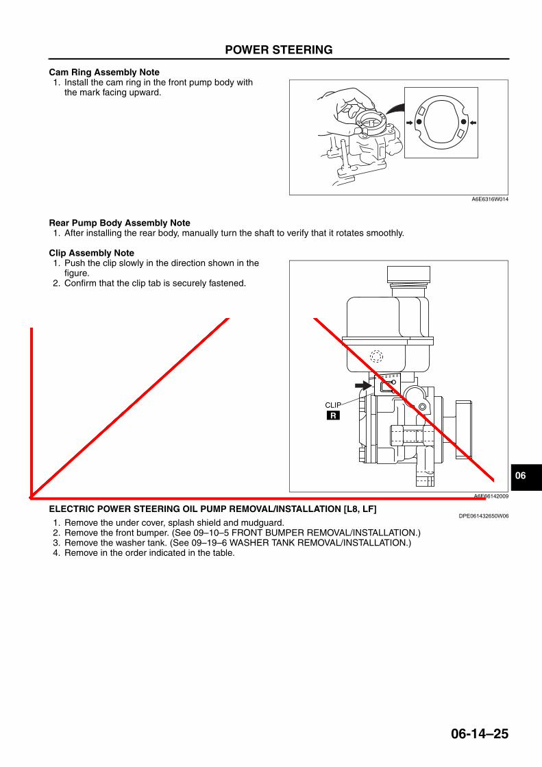
Cam Ring Assembly Note1. Install the cam ring in the front pump body with
the mark facing upward.
Rear Pump Body Assembly Note1. After installing the rear body, manually turn the shaft to verify that it rotates smoothly.
Clip Assembly Note1. Push the clip slowly in the direction shown in the
figure.2. Confirm that the clip tab is securely fastened.
End Of Sie
ELECTRIC POWER STEERING OIL PUMP REMOVAL/INSTALLATION [L8, LF]DPE061432650W06
1. Remove the under cover, splash shield and mudguard.2. Remove the front bumper. (See 09–10–5 FRONT BUMPER REMOVAL/INSTALLATION.)3. Remove the washer tank. (See 09–19–6 WASHER TANK REMOVAL/INSTALLATION.)4. Remove in the order indicated in the table.
A6E6316W014
CLIP
R
A6E66142009
v018898
06 Cam Ring Assembly Note 1. Install the cam ring in the front pump body with the mark facing upward. Rear Pump Body Assembly Note 1. After installing the rear body, manually turn the shaft to verify that it rotates smoothly. Clip Assembly Note 1. Push the clip slowly in the direction shown in the figure. 2. Confirm that the clip tab is securely fastened. End Of Sie A6E6316W014 CLIP R A6E66142009
v018898
v018898
v018898

06-14–26
POWER STEERING
5. Install in the reverse order of removal..
End Of SieELECTRO HYDRAULIC POWER ASSIST STEERING (EHPAS) CONTROL MODULE INSPECTION
DPE061432650W03Terminal Voltage Table (Reference)
R
1
2
3 5
4
R
7
5
R
6
19—25{2.0—2.5, 15—18}
19—25{2.0—2.5, 15—18}
19—25{2.0—2.5, 15—18}
29.4—44.1{3.00—4.49,21.7—32.5}
9—11 N·m{92—112 kgf·cm, 80—97 in·lbf}
9—11 N·m{92—112 kgf·cm,80—97 in·lbf}
9—11 N·m{92—112 kgf·cm,80—97 in·lbf}
N·m {kgf·m, ft·lbf}
DPE614ZW1014
1 Connector2 Pressure pipe3 Sub-tank4 Electric power steering oil pump and bracket
component
5 Bracket6 Return hose7 Electric power steering oil pump
Terminal Signal name Connected to Measured item
Measured terminal (measured condition) Standard Inspection item(s)
1A Ground Ground point Voltage Under any condition 1 V or less • Wiring harness (1A—ground point)
1B Battery power supply Battery Voltage Under any condition B+
• Wiring harness (1B—battery)
• Fuse (EHPAS 80 A)2A — — — — — —2B CAN-L — Inspect under DTC inspection. —2C — — — — — —2D CAN-H — Inspect under DTC inspection. —
1A2A2E
2D2C
2B2F1B3A
3D
3C
3B
EHPAS CONTROL MODULE HARNESS-SIDE CONNECTOR
DPE614ZW1015

POWER STEERING
06-14–27
06
* : With ABS
End Of SieELECTRO HYDRAULIC POWER ASSIST STEERING (EHPAS) CONTROL MODULE CONFIGURATION
DPE061432650W051. Turn the ignition switch off.2. Connect the WDS or equivalent to the DLC-2.3. Input vehicle information following the directions
on the screen of the WDS or equivalent.4. Select “Module programming” from the WDS or
equivalent menu.5. Select “Programmable Module Installation”.6. Select “EPS”.7. Clear DTCs using the WDS or equivalent, then
verify that there is no DTC present.End Of Sie
2E — — — — — —
2F Ignition power supply Ignition switch Voltage
Ignition switch is ON B+ • Wiring harness (2F—ignition switch—battery)
• Fuse (EHPAS 5A)Ignition switch is OFF 1 V or less
3A* Steering angle sensor ground
Steering angle sensor Continuity Continuity Continuity
detected
• Wiring harness (3A—steering angle sensor D)
3BSteering angle sensor(signal 1)
Steering angle sensor Continuity Continuity Continuity
detected
• Wiring harness (3B—steering angle sensor B)
3DSteering angle sensor(signal 2)
Steering angle sensor Continuity Continuity Continuity
detected
• Wiring harness (3D—steering angle sensor C)
Terminal Signal name Connected to Measured item
Measured terminal (measured condition) Standard Inspection item(s)
DLC-2
DPE402AW1005

TECHNICAL DATA
06–50–1
06
06–50 TECHNICAL DATASTEERING TECHNICAL DATA. . . . . . . . 06–50–1
End of Toc
STEERING TECHNICAL DATADPE065000000W01
* : When reservoir tank is at maximum volume.
End Of Sie
Item SpecificationPower steering fluid type ATF M-III or equivalent (e.g. Dexron ® II)
Power steering fluid capacity* (approximate quantity)L8, LF: 0.8 L {0.85 US qt, 0.70 lmp qt}
MZR-CD (RF Turbo): 0.97 L {1.03 US qt, 0.85 Imp qt}
Oil pump fluid pressure(oil temperature 50—60 °C {122—140 °F})
L8,LF: 10.4—11.0 MPa {107—112 kgf/cm2, 1509—1595 psi} MZR-CD (RF Turbo):
10.50—10.99 MPa {107.1—112.0 kgf/cm2, 1523—1593 psi}
Gear housing fluid pressure (oil temperature 50—60 °C {122—140 °F})
L8, LF: 9.0—11.0 MPa {92—111 kgf/cm2, 1,306—1,585 psi}MZR-CD (RF Turbo):
10.50—10.99 MPa {107.1—112.0 kgf/cm2, 1,523—1,593 psi}Steering wheel play 0—30 mm {0—1.18 in} (When hydraulic operating)Steering wheel force 7.8 N·m {80 kgf·cm, 69 in·lbf} or less (reference value)Steering shaft length 335.8—340.8 mm {13.23—13.41 in}
Steering rack runout Large diameter portion: 0.15 mm {0.006 in} max.Small diameter portion: 0.20 mm {0.008 in} max.
Tie-rod end rotational torque 0.5—3.0 N·m {6—30 kgf·cm, 5—26 in·lbf}
Tie rod swing torque 0.4—4.0 N·m {5—40 kgf·cm, 4—35 in·lbf}[Pull scale reading 0.6—29.3 N {0.06—2.98 kgf, 0.14—6.58 lbf}]
Pinion shaft rotation torque Center of rack ± 90°: 0.88—1.48 N·m {8.98—15.0 kgf·cm, 7.79—13.0 in·lbf}
v018898
v018898
v018898
v018898
v018898
v018898
v018898
v018898

SERVICE TOOLS
06–60–1
06
06–60 SERVICE TOOLSSTEERING SST. . . . . . . . . . . . . . . . . . . . 06–60–1
End of Toc
STEERING SSTDPE066000000W01
End Of Sie
49 1232 670B
Power steering gauge set
49 H002 671
Adapter
49 G032 3A4A
Power steering gauge adapter set
49 B034 202A
Support block
49 F017 1A0
Universal wrench
49 D032 316
Protractor
49 F032 303
Handle
49 B032 323
Rod seal remover body
49 N032 319A
Support plate
49 G033 102
Handle
49 T028 301
Dust boot installer
49 F015 002Water seal installer
49 F032 304
Body
49 F032 310
Protector
49 H032 301
Wrench
49 G032 3A1
Joint hose set
49 F032 301
Power steering pump hanger
WDS
v018898
49 F032 301 Power steering pump hanger
v018898
v018898