HYBRID PROPELLANT ROCKETS - engineering108.com · HYBRID PROPELLANT ROCKETS ... lower...
29
CHAPTER 15 HYBRID PROPELLANT ROCKETS Terry A. Boardman* Rocket propulsion concepts in which one component of the propellant is stored in liquid phase while the other is stored in solid phase are called hybrid propulsion systems. Such systems most commonly employ a liquid oxidizer and solid fuel t. Various combinations of solid fuels and liquid oxidizers as well as liquid fuels and solid oxidizers have been experimentally evaluated for use in hybrid rocket motors. Most common is the liquid oxidizer-solid fuel concept shown in Fig. 15-1. Illustrated here is a large pressure-fed hybrid booster configuration. The means of pressurizing the liquid oxidizer is not an important element of hybrid technology and a turbopump system could also perform this task. $ The oxidizer can be either a noncryogenic (storable) or a cryogenic liquid, depending on the application requirements. In this hybrid motor concept, oxidizer is injected into a precombustion or vaporization chamber upstream of the primary fuel grain. The fuel grain con- tains numerous axial combustion ports that generate fuel vapor to react with *This is a revision of Chapter 15 in the 6th edition of Rocket Propulsion Elements originally authored by Terry A. Boardman, Alan Holzman, and George P. Sutton. t The term hybrid has also been applied to liquid monopropellant systems, electrical propulsion systems where a resistor or electric arc raises the temperature of the reaction gases, solid propulsion systems utilizing separate fuel-rich and oxidizer-rich propellant grains (so called solid-solid hybrid), or the solid fuel ramjet that has a combustion cycle very similar to the hybrid concept discussed in this chapter. The solid fuel ramjet is mentioned briefly in Chapter 1. ~Hybrid technology in this context is construed to encompass combustion physics, fuel grain design, and materials selection for nozzle and internal case insulators. The choice of pressure feeding or turbopump feeding oxidizer to the combustion chamber impacts vehicle performance through differences in mass fraction and specific impulse, but is considered an element of liquid propulsion technology rather than hybrid technology. 579
-
Upload
truongthuy -
Category
Documents
-
view
258 -
download
0
Transcript of HYBRID PROPELLANT ROCKETS - engineering108.com · HYBRID PROPELLANT ROCKETS ... lower...

CHAPTER 15
HYBRID PROPELLANT ROCKETS Terry A. Boardman*
Rocke t p ropuls ion concepts in which one c o m p o n e n t of the propel lant is s tored in liquid phase while the other is s tored in solid phase are called hybrid propuls ion systems. Such systems most common ly employ a liquid oxidizer and solid fuel t . Various combina t ions of solid fuels and liquid oxidizers as
well as liquid fuels and solid oxidizers have been experimental ly evaluated for use in hybrid rocket motors . Mos t c o m m o n is the liquid oxidizer-sol id fuel concept shown in Fig. 15-1. I l lustrated here is a large pressure-fed hybrid boos ter configurat ion. The means of pressurizing the liquid oxidizer is not an impor t an t element of hybrid technology and a t u r b o p u m p system could also pe r fo rm this task. $ The oxidizer can be either a noncryogenic (storable) or a cryogenic liquid, depending on the appl icat ion requirements .
In this hybrid m o t o r concept , oxidizer is injected into a p recombus t ion or vapor iza t ion chamber ups t ream of the pr imary fuel grain. The fuel grain con- tains numerous axial combus t ion ports that generate fuel vapor to react with
*This is a revision of Chapter 15 in the 6th edition of Rocket Propulsion Elements originally authored by Terry A. Boardman, Alan Holzman, and George P. Sutton. t The term hybrid has also been applied to liquid monopropellant systems, electrical propulsion systems where a resistor or electric arc raises the temperature of the reaction gases, solid propulsion systems utilizing separate fuel-rich and oxidizer-rich propellant grains (so called solid-solid hybrid), or the solid fuel ramjet that has a combustion cycle very similar to the hybrid concept discussed in this chapter. The solid fuel ramjet is mentioned briefly in Chapter 1. ~Hybrid technology in this context is construed to encompass combustion physics, fuel grain design, and materials selection for nozzle and internal case insulators. The choice of pressure feeding or turbopump feeding oxidizer to the combustion chamber impacts vehicle performance through differences in mass fraction and specific impulse, but is considered an element of liquid propulsion technology rather than hybrid technology.
579

580 HYBRID PROPELLANT ROCKETS
Pressurization system
F LO2 oxidizer
/ - Systems tunnel
~ ' ~ f--- Graphite/aluminum LO 2 tank
Concept features
• Throttleable • Inert fuel grain • Simple injector
Hypergolic igniter
LO 2 injector
~-Inert HTPB fuel grain
~ , /--Graphite composite case
~ " ~ .... r-- Combustion ports > ~ .
f-- Mixing chamber
Flex bearing TVC { ~"Y'x .
FIGURE 15-1. Large hybrid rocket booster concept capable of boosting the Space Shuttle. It has an inert solid fuel grain, a pressurized liquid oxygen feed system, and can be throttled.
the injected oxidizer. An aft mixing chamber is employed to ensure that all fuel and oxidizer are burned before exiting the nozzle.
The main advantages of a hybrid rocket propulsion system are: (1) safety during fabrication, storage, or operation without any possibility of explosion or detonation; (2) start-stop-restart capabilities; (3) relatively low system cost; (4) higher specific impulse than solid rocket motors and higher density-specific impulse than liquid bipropellant engines; and (5) the ability to smoothly change motor thrust over a wide range on demand.
The disadvantages of hybrid rocket propulsion systems are: (1) mixture ratio and, hence, specific impulse will vary somewhat during steady-state operation and throttling; (2) lower density-specific impulse than solid propellant systems; (3) some fuel sliver must be retained in the combustion chamber at end-of- burn, which slightly reduces motor mass fraction; and (4) unproven propulsion system feasibility at large scale.
15.1. APPLICATIONS AND PROPELLANTS
Hybrid propulsion is well suited to applications or missions requiring throt- tling, command shutdown and restart, long-duration missions requiring stor- able nontoxic propellants, or infrastructure operations (manufacturing and

15.1. APPLICATIONS AND PROPELLANTS 581
launch) that would benefit from a non-self-deflagrating propulsion system. Such applications would include primary boost propulsion for space launch vehicles, upper stages, and satellite maneuvering systems.
Many early hybrid rocket motor developments were aimed at target missiles and low-cost tactical missile applications (Ref. 15-1). Other development efforts focused on high-energy upper-stage motors. In recent years develop- ment efforts have concentrated on booster prototypes for space launch appli- cations. Design requirements for one target missile, which entered production in the early 1970s, included a nominal thrust of 2200 N with an 8:1 throttling range, storable liquid oxidizer, and engine shutdown on command. Selected propellants included a nitrogen tetroxide/nitrous oxide oxidizer and a hydro- carbon fuel grain composed of polymethylmethacrylate (plexiglass) and mag- nesium (Ref. 15-2). Values of vacuum-delivered specific impulse for such storable propellant systems range between 230 and 280 sec. In another pro- gram (Ref. 15-3), a hybrid motor was developed for high-performance upper- stage applications with design requirements that included a nominal thrust level of 22,240 N and an 8:1 throttling range. Oxygen difluoride was selected as the oxidizer for use with a lithium hydride/polybutadiene fuel grain. Analytical and experimental investigations have been made using other high- performance propellants. High-energy oxidizers include fluorine/liquid oxygen mixtures (FLOX) and chlorine/fluorine compounds such as CIF3 and CIFs. Complementary high-energy fuels are typically hydrides of light metals, such as beryllium, lithium, and aluminum, mixed with a suitable polymeric binder (Ref. 15-4). Delivered vacuum-specific impulse levels for these high-energy hybrid propellants are in the 350 to 380 sec range, depending on nozzle expan- sion ratio. Combustion efficiencies of 95% of theoretical values have been achieved in tests with these propellants; however, none of these exotic formula- tion systems have seen use on flight vehicles.
A more practical, although lower energy, upper-stage hybrid propellant system is 90 to 95% hydrogen peroxide oxidizer combined with hydroxyl- terminated polybutadiene (HTPB) fuel. Hydrogen peroxide is considered stor- able for time periods typical of upper-stage mission cycles (oxidizer tanking to mission completion on the order of several months) and is relatively inexpen- sive. In solid rocket motors, HTPB is used as the binder to consolidate the aluminum fuel and ammonium perchlorate oxidizer matrix. In a hybrid, HTPB becomes the entire fuel constituent. HTPB is low cost, processes easily, and will not self-deflagrate under any conditions.
The propellant system of choice for large hybrid booster applications is liquid oxygen (LOX) oxidizer and HTPB fuel. Liquid oxygen is a widely used oxidizer in the space launch industry, is relatively safe, and delivers high performance at low cost. This hybrid propellant combination produces a nontoxic, relatively smoke-free exhaust. The LOX/HTPB propellant combi- nation favored for booster applications is chemically and performance-wise equivalent to a LOX-kerosene bipropellant system.
5 8 2 HYBRID PROPELLANT ROCKETS
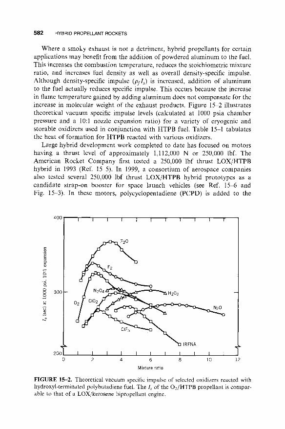
Where a smoky exhaust is not a detriment, hybrid propellants for certain applications may benefit from the addition of powdered aluminum to the fuel. This increases the combustion temperature, reduces the stoichiometric mixture ratio, and increases fuel density as well as overall density-specific impulse. Although density-specific impulse (pfls) is increased, addition of aluminum to the fuel actually reduces specific impulse. This occurs because the increase in flame temperature gained by adding aluminum does not compensate for the increase in molecular weight of the exhaust products. Figure 15-2 illustrates theoretical vacuum specific impulse levels (calculated at 1000 psia chamber pressure and a 10:1 nozzle expansion ratio) for a variety of cryogenic and storable oxidizers used in conjunction with HTPB fuel. Table 15-1 tabulates the heat of formation for HTPB reacted with various oxidizers.
Large hybrid development work completed to date has focused on motors having a thrust level of approximately 1,112,000 N or 250,000 lbf. The American Rocket Company first tested a 250,000 lbf thrust LOX/HTPB hybrid in 1993 (Ref. 15-5). In 1999, a consortium of aerospace companies also tested several 250,000 lbf thrust LOX/HTPB hybrid prototypes as a candidate strap-on booster for space launch vehicles (see Ref. 15-6 and Fig. 15-3). In these motors, polycyclopentadiene (PCPD) is added to the
c ._o c
x
..
o
o o o
.+_,
400 ....
300 -
2O0 0
I i I i I I i i i i !
F20
ClF5
H202
IRFNA
N20
I I I I I I I I I I I 2 4 6 8 10
Mixture ratio
12
F I G U R E 15-2. Theoretical vacuum specific impulse of selected oxidizers reacted with hydroxyl-terminated polybutadiene fuel. The Is of the O2/HTPB propellant is compar- able to that of a LOX/kerosene bipropellant engine.

15.1. APPLICATIONS AND PROPELLANTS 5113
TABLE 15-1. Thermochemical Properties of Selected Oxidizers Reacted with HTPB Fuel
Boiling Point Density A f H a Oxidizer Type (°C) (g/cm3) (kcal/mol)
0 2 Cryogenic - 183 1.149 - 3.1 F 2 Cryogenic - 188 1.696 -3.0 03 Cryogenic -112 1.614 + 30.9 F20 Cryogenic -145 1.650 +2.5 F202 Cryogenic -57 1.450 + 4.7 N20 Cryogenic -88 1.226 + 15.5 N204 Storable + 21 1.449 + 2.3 IRFNA b Storable + 80 to + 120 1.583 -41.0 H202 Storable + 150 1.463 44.8 C102 Storable + 11 1.640 + 24.7 C1F3 Storable + 11 1.810 -44.4
a A f H is the heat of formation as defined in Chapter 5. bInhibited red fuming nitric acid.
HTPB fuel to increase fuel density by about 10% over HTPB alone. The motors were designed to operate for 80 sec at a LOX flow rate of 600 lbm/sec with a maximum chamber pressure of 900 psi. Figure 15-4 illustrates a cross section of one motor configuration. Test results indicated additional work is necessary to develop large hybrid motor configurations that exhibit stable combustion throughout the motor burn, and in understanding fuel regres- sion-rate scale-up factors.
A hybrid fuel grain is ignited by providing a source of heat, which initiates gasification of the solid fuel grain at the head end of the motor. Subsequent initiation of oxidizer flow provides the required flame spreading to fully ignite the motor. Ignition is typically accomplished by injection of a hypergolic fluid into the motor combustion chamber. Using the motor described in Fig. 15-4 as an example, a mixture of triethyl aluminum (TEA) and triethyl borane (TEB) is injected into the vaporization chamber. The TEA/TEB mixture ignites spontaneously on contact with air in the combustion chamber, vaporizing fuel in the dome region. Subsequent injec- tion of liquid oxygen completes ignition of the motor. TEA/TEB mixtures are currently used for motor ignition in the Atlas and Delta commercial launch vehicles. Experimenters (Refs. 15-7 and 15-8) have described solid fuels that will ignite spontaneously at ambient temperature and pressure when sprayed with specific oxidizers other than LOX. Small hybrid motors, such as those used in a laboratory environment with gaseous oxygen oxidi- zer, are often electrically ignited by passing current through a resistor such as steel wool located in the combustion port, or by use of a propane or hydrogen ignition system.

FIGURE 15-3. Static tests of a 250,000 lbf thrust hybrid motor prototype demonstrated that additional work is needed to understand fuel regression and combustion stability issues at large scale. The fuel case shown here is approximately 6.3 ft diameter.

15.2. PERFORMANCE ANALYSIS AND GRAIN CONFIGURATION 585
SECTION A-A SECTION B-B
LOX Injector I Port (18-in. dia)
/ ~ ~ Vapor]ization Chamber Fins Ultrasonic Transducer . . . . •,,,,,. Vaponzatlon Chamber Mare Gram . . . . . Configuration Configuration Mixing Chamber--
B ~L /
/ B ~ - - HTPB/PCPD Fuel Fuel - - - - / L__ Flow Deflector
/ i___ A588 Steel Case EPDM Insulation (73-in. OD) EPDM ----,
512 in. . •
546 in.
Simulated Submerged-- Flex Bearing Nozzle
(3-D carbon-carbon throat)
FIGURE 15-4. 250,000 lbf thrust hybrid booster design parameters and section of fuel grain and nozzle. The vaporization chamber fins and flow deflector are designed to promote flame holding in combustion ports.
Maximum operating pressure Maximum vacuum thrust Throat diameter, initial Nozzle expansion ratio, initial Liquid oxygen flow rate Fuel weight Burn time
900 psia 250,000 lbf 14.60 in. 12 420 to 600 lbm/sec (throttlable) 45,700 lbf 80 sec
15.2. PERFORMANCE ANALYSIS AND GRAIN CONFIGURATION
A characteristic operating feature of hybrids is that the fuel regression rate is typically less than one-third that of composite solid rocket propellants. It is very difficult to obtain fuel regression rates comparable to propellant burn rates in solid rocket motors. Consequently, practical high-thrust hybrid motor designs must have multiple perforations (combustion ports) in the fuel grain to produce the required fuel surface area. The performance of a hybrid motor (defined in terms of delivered specific impulse) depends critically on the degree of flow mixing attained in the combustion chamber. High performance stems from high combustion efficiency that is a direct function of the thoroughness with which unburned oxidizer exhausting from the combustion port is mixed with unburned fuel from within sublayers of the boundary layer. Multiple combustion ports serve to promote high com- bustion efficiency as a result of the turbulent mixing environment for unreacted fuel and oxidizer in the mixing chamber region downstream of the fuel grain.
586 HYBRID PROPELLANT ROCKETS
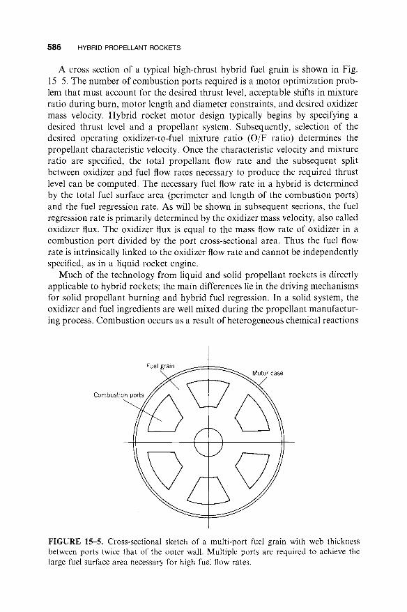
A cross section of a typical high-thrust hybrid fuel grain is shown in Fig. 15-5. The number of combustion ports required is a motor optimization prob- lem that must account for the desired thrust level, acceptable shifts in mixture ratio during burn, motor length and diameter constraints, and desired oxidizer mass velocity. Hybrid rocket motor design typically begins by specifying a desired thrust level and a propellant system. Subsequently, selection of the desired operating oxidizer-to-fuel mixture ratio (O/F ratio) determines the propellant characteristic velocity. Once the characteristic velocity and mixture ratio are specified, the total propellant flow rate and the subsequent split between oxidizer and fuel flow rates necessary to produce the required thrust level can be computed. The necessary fuel flow rate in a hybrid is determined by the total fuel surface area (perimeter and length of the combustion ports) and the fuel regression rate. As will be shown in subsequent sections, the fuel regression rate is primarily determined by the oxidizer mass velocity, also called oxidizer flux. The oxidizer flux is equal to the mass flow rate of oxidizer in a combustion port divided by the port cross-sectional area. Thus the fuel flow rate is intrinsically linked to the oxidizer flow rate and cannot be independently specified, as in a liquid rocket engine.
Much of the technology from liquid and solid propellant rockets is directly applicable to hybrid rockets; the main differences lie in the driving mechanisms for solid propellant burning and hybrid fuel regression. In a solid system, the oxidizer and fuel ingredients are well mixed during the propellant manufactur- ing process. Combustion occurs as a result of heterogeneous chemical reactions
Combusti F ~
_. Motor case
FIGURE 15-5. Cross-sectional sketch of a multi-port fuel grain with web thickness between ports twice that of the outer wall. Multiple ports are required to achieve the large fuel surface area necessary for high fuel flow rates.

15.2. PERFORMANCE ANALYSIS AND GRAIN CONFIGURATION 587
on or very near the surface of the solid propellant. The solid propellant burning rate is controlled by chamber pressure and follows the well-established law of Eq. 11-3; it is Eq. 15-1 in this chapter.
~ - ap~ (15-1)
where a and n are empirical coefficients derived experimentally for specific propellant formulations. Since the rate of propellant gasification per unit area in a solid rocket motor, at a given propellant bulk temperature and in the absence of erosive burning, is determined only by chamber pressure, motor thrust is predetermined by the initial propellant grain surface area and grain geometrical characteristics. Throttling or extinguishment is very difficult to achieve in practical solid rocket motor configurations since the fuel and oxidi- zer cannot be separated.
As the fuel grain of a hybrid typically contains no oxidizer, the combustion process and hence the regression of the fuel surface is markedly different from that of a solid rocket motor. Because the solid fuel must be vaporized before combustion can occur, the fuel surface regression is intrinsically related to the coupling of combustion port aerodynamics and heat transfer to the fuel grain surface. The primary combustion region over the fuel grain surface has been shown to be limited to a relatively narrow flame zone occurring within the fuel grain boundary layer (Ref. 15-9). Factors affecting the development of the fuel grain boundary layer and, hence, fuel regression characteristics include pres- sure, gas temperature, grain composition, combustion port oxidizer mass flow rate, and combustion port length. The heat transfer relationships between the gas and solid phase depend on whether the boundary layer is laminar or turbulent. In a typical hybrid using oxygen as the oxidizer, the Reynolds num- ber per unit length is on the order of 1 to 2 x 10⁵ per inch of grain length for flux levels between 0.3 and 0.6 lbm/sec/in. 2 (see Appendix 4 for definitions of non-dimensional parameters used in hybrid boundary layer analyses). Thus, the properties of a turbulent boundary layer govern the convective heat trans- fer processes to non-metallized fuel grains.
In hybrids with metallized fuel grains, radiation from the metal oxide par- ticle cloud in the combustion port contribues a major portion of the total heat flux to the fuel grain. The local regression rate of the fuel is also quite sensitive to the general turbulence level of the combustion port gas flow (Refs. 15-10 and 15-11). Localized combustion gas eddies or recirculation zones adjacent to the fuel surface act to significantly enhance the regression rate in these areas. Hybrid fuel regression rate is thought to be insensitive to fuel grain bulk temperatures over the range in which solid rocket motors may operate ( -65°F to 165°F). This is due to the absence of heterogeneous fuel/oxidizer reactions at the fuel surface (in which the reaction rates are temperature depen- dent) and because, over the above temperature range, the change in heat con- tent of the solid fuel is small compared to the heat necessary to initiate vaporization of the fuel surface.

5 8 8 HYBRID PROPELLANT ROCKETS
Selection of fuel ingredients can also have a significant impact on the grain regression rate, which is largely a function of the energy required to convert the fuel from solid to vapor phase (hv). This energy is called the heat of gasification and, for polymeric fuels, includes the energy required to break polymer chains (heat of depolymerization) and the heat required to convert polymer fragments to gaseous phase (heat of vaporization). The term "heat of vaporization" is often used as a catchall phrase to include all decomposi- tion mechanisms in hybrid fuels. In non-metallized fuels, low heats of gasi- fication tend to produce higher regression rates. In metallized fuels, the addition of ultra-fine aluminum (UFA1) powder (particle sizes on the order of 0.05 lam to 0.1 gm) to HTPB has been noted to significantly increase the fuel regresion rate relative to a pure HTPB baseline (see Ref. 15-12 and Fig. 15-6). Hybrid propellants containing aluminum particles with diameters typi- cal of those used in solid rocket propellants (40 gm to 400 gm) do not exhibit this effect.
Figure 15-7 depicts a simplified model of the hybrid combustion process for a non-metallized (non-radiating) fuel system. Fuel is vaporized as a result of heat transferred from the flame zone to the fuel mass. Vaporized fuel is con- vected upward toward the flame zone while oxidizer from the free stream (core flow) is transported to the flame zone by diffusion and flow turbulence. The flame is established at a location within the boundary layer determined by the stoichiometric conditions under which combustion can occur. The thickness of the flame is determined primarily by the rate at which the oxidation reaction
80
m 70 n t - -1- ~ 60 Q.
~ 50
Q. m 40 l - -
"~ :30
• 20 c ° ~
. . . . J . . . . I . . . . I . . . . 1 . . . .
0 5 10 15 20
Mass fraction of UFAI (wt% of total HTPB fuel)
25
FIGURE 15-6. Ultra-fine aluminum (UFAL) powder mixed with HTPB significantly increases the fuel regression rate.

15.2. PERFORMANCE ANALYSIS AND GRAIN CONFIGURATION 589
To liquid injector To nozzle
Liquid spray and gas
i::ii Heat fl
Combustion port Border of boundary layer
Combustion reaction products Bou ndary layer
~ : : ; : i A c t i v e combustion zone
j J t /
id phase
Heat flow
Diffusion flame zone
Fuel vapor zone
Motor case
FIGURE 15-7. Simplified model of the diffusion-controlled hybrid combustion pro- cess, illustrating the flame zone embedded within the fuel boundary layer.
occurs. This rate is largely dependent on pressure and typically follows an Arrhenius relationship.
The mechanisms of heat transfer to the fuel grain surface in a hybrid are convection and radiation. In a non-metallized fuel grain, at pressures and flux levels of interest for propulsion applications, heat transferred by convection is thought to be much larger than that transferred by gas-phase radiation or radiation from soot particles in the flow. As a result, the basic characteristics of fuel grain regression may be explored via an analysis of convective heat transfer in a turbulent boundary layer (see Appendix 4). Considering an energy balance at the fuel grain surface, one may derive an expression for the fuel surface regression rate as
G0.8 I; -- 0.036 / \{/Z} 0"21~0.23 (15--2)
p j , ,
where G is the free stream propellant mass velocity (total oxidizer and fuel flow per unit area) in a combustion port at any given axial location x, pf is the solid- phase fuel density,/x is the combustion gas viscosity, and/3 is the non-dimen- sionalized fuel mass flux, resulting from fuel vaporization, evaluated at the fuel surface. The parameter/~ is frequently referred to as a blowing coefficient (see Appendices 4 and 5 for further discussion of 13). Equation 15-2 indicates that hybrid fuel regression rate for a non-radiative system is strongly dependent on G and rather weakly dependent on axial location (x) and fuel blowing char-

590 HYBRID PROPELLANT ROCKETS
acteristics (/3). One may also note that the regression rate is not explicitly dependent on chamber pressure in this derivation. In fact, experiments have shown that the regression rate for some fuels exhibits little or no dependence on chamber pressure whereas the regression rate for others exhibits a strong dependence. In particular, metallized hybrid fuel systems exhibit a pronounced pressure dependence (Ref. 15-13).
As the combustion port length increases, fuel added to the port mass flow increases the total port mass flux. In ports operating at low mixture ratios, the fuel mass increase may be on the same order as the oxidizer mass flow initially entering the port. Given the weak dependence of regression rate on x in Eq. 15- 2, one would therefore expect the fuel regression rate to increase with increas- ing axial length due to the increase in G. While this generally turns out to be the case, fuel regression rate has been observed to both increase and decrease with increasing x, depending on specifics of the motor configuration. In practice, axial fuel regression characteristics are strongly influenced by oxidizer injection and pre-combustion/vaporization chamber design characteristics. General trends that have been measured in hybrid combustion ports include the follow- ing as x increases: total mass flux increases; boundary layer thickness grows; flame standoff from the fuel surface increases; combustion port average gas temperature increases; oxidizer concentration decreases.
Since the blowing coefficient/3 is not only an aerodynamic parameter but also a thermochemical parameter (see Appendix 5) and the x dependency is of the same order as/3 in Eq. 15-2, this expression is often simplified for purposes of preliminary engineering design by lumping effects of x,/3, fuel density, and gas viscosity into one parameter, a. In practice, deviations from the theoretical 0.8 power mass velocity dependency are also often noted. The result of sim- plifying Eq. 15-2 is to retain the functional form but fit the free constants a and n using experimental data obtained from characterizing specific fuel and oxi- dizer combinations. One functional form useful for engineering evaluations is
i" - aG~o (15-3)
where Go is the oxidizer mass velocity, which is equal at any time to the oxidizer flow rate divided by the combustion port area. The value of i: has been observed to vary from 0.05 in./sec to 0.2 in./sec. Likewise, n has been observed to fall in a range between 0.4 and 0.7. An alternative form of Eq. 15- 3, to account for an observed pressure and/or port diameter dependency, is given as
/; n m l - aGopl Dp (15-4)
where m and l have been observed to vary between zero and 0.25 and zero and 0.7, respectively.
Figure 15-8 illustrates surface regression rate data obtained for the combus- tion of HTPB fuel grains and gaseous oxygen in rocket motor tests at two

15.2. P E R F O R M A N C E ANALYSIS AND GRAIN C O N F I G U R A T I O N 5 9 1
"G" 0.1 (D ¢/)
c "
(D
L_
E 0
GO Q)
L_
u.. 0.01 0.01
I I
• Labscale motor - - - r = O. 10460.686
I I 1 I I I I I I I I I I I _
o 11-in diameter motor - - i" = 0.0656°77(Dp/3) °'71 ~ . ~ t y "° -
I I I 1 I 1 I I I I I I I I 1 I I
0.1 1 Oxygen mass velocity (Ibm/sec-in 2)
FIGURE 15-8. Hybrid regression rate has been observed to decrease as motor scale (combustion port diameter) increases.
different scales. The first data set were obtained by testing fuel grains in a small laboratory-scale (2-in. motor diameter with a 0.43-in. combustion port dia- meter) rocket at varying gaseous oxygen flux levels (Ref. 15-14). A least- squares regression analysis, performed to determine the constants in Eq. 15- 3, indicates that, at this scale, the following relationship best describes the regression rate characteristics of HTPB as a function of oxygen mass flux:
t:HTPB -- 0.104G 0"681 (15-5)
Data obtained with the same propellant system in a larger 11-in. diameter hybrid motor with combustion port diameters ranging between 3 and 6 in. exhibited a relatively strong dependence on combustion port diameter (Ref. 15-15). Data from this testing was best matched with an expression in the form of Eq. 15-4:
f ' H T P B - - 0 . 0 6 5 G ° o " 7 7 ( D p / 3 ) 0"71 (15-6)
The difference in fuel regression characteristics between the two motor scales illustrates one of the central difficulties of hybrid motor design, i.e., that of scaling ballistic performance. Scaling issues in hybrid motors are currently not well understood (in part because of the lack of sufficient valid data for different motor sizes) and the literature abounds with empirical regression rate scaling relationships (Ref. 15-16). Computational fluid dynamic approaches to resol- ving the hybrid flow field and calculating fuel surface heating appear to offer the best hope of analytically evaluating scale effects.
The dynamic behavior of a hybrid rocket may be analyzed using the con- tinuity equation
O(p, v,)
Ot = thin - rhout (15-7)
592 HYBRID PROPELLANT ROCKETS
that expresses that the time rate of change of high-pressure gas inside the chamber is equal to the difference between the hot gas generated from inflow of liquid oxidizer, plus that generated from the regressing fuel surface, and the flow through the nozzle. Equation 15-7 may be rewritten as
O(Pl Vl) - mo --t- rhf p lA t 0 ~ -- c* ( 1 5 - 8 )
When steady state is reached, Eq. 15-8 reduces to
rn - rn o + rhf p l a t -- c* ( 1 5 - 9 )
The thrust of a hybrid rocket motor can then be expressed as
F = rhlsgo = (rho + rhf)Isgo (15-10)
Changing the thrust or throttling of a hybrid is achieved by changing the oxidizer flow rate, usually by means of a throttling valve in the oxidizer feed line. The fuel flow is a function of the oxidizer flow but not necessarily a linear function. For circular port geometries with radius R, Eq. 15-3 may be recast as
rh° ) n (15-11) i - a ~
The mass production rate of fuel is given by
rhf = pf Abi" = 2rrpf R L i (15-12)
where Ab is the combustion port surface area and L is the port length. Combining Eqs. 15-11 and 15-12, one obtains the fuel production rate in terms of port radius and oxidizer mass flow rate:
rnf -- 27r 1-npfLaril~R 1-2n (15-13)
From this expression one will note that, for the particular value of n - ½, the fuel mass flow rate is independent of combustion port radius and varies as the square root of oxidizer mass flow rate. For such a situation, if the oxidizer flow is reduced to one-half of its rated value, then the fuel flow will be reduced by a factor of 0.707 and the motor thrust, which depends on the total propellant flow (rnf + rno), will not vary linearly with the change in oxidizer flow. Usually, as the thrust is decreased by reducing the oxizider flow, the mixture ratio (rho/rnf) is reduced, becoming increasingly fuel rich. In some hybrid motor concepts, a portion of the oxidizer is injected in a mixing chamber downstream of the fuel grain in order to maintain a more constant mixture ratio. However,

15.3. DESIGN EXAMPLE 593
for most applications, the system design can be optimized over the range of mixture ratios encountered with very little degradation of average specific impulse due to throttling.
Equation 15-13 also indicates that, for constant oxidizer flow, fuel produc- tion will increase with increasing port radius if n < ½. For n > l, fuel production will decrease with increasing port radius.
For a fuel grain incorporating N circular combustion ports, Eq. 15-11 can be simply integrated to give combustion port radius, instantaneous fuel flow rate, instantaneous mixture ratio, and total fuel consumed as functions of burn time:
Combustion port radius R as a function of time and oxidizer flow rate:
1
R ( t ) - a(2n+l) ~-~ t + (15-14)
Instantaneous fuel flow rate:
rho)" rhf(t) - 2rrN pf La - ~
- 2 n
a(2n + 1) ~-~ t + (15-15)
Instantaneous mixture ratio:
mf 2pfLa ~ a(2n + 1) ~ t + (15-16)
Total fuel consumed:
mo n R~n+l ~ mf ( t ) - - r rNpfL a(2n+l) ~-~ t + • - R (15-17)
where L is the fuel grain length, R; is the initial port radius, N is the number of combustion ports of radius R; in the fuel grain, and rho and rhf are the total oxidizer and fuel flow rates, respectively. Although the above equations are strictly valid only for circular combustion ports, they may be used to give a qualitative understanding of hybrid motor behavior which is applicable to the burnout of non-circular ports as well.
15.3. DESIGN EXAMPLE
The preliminary design problem typically posed is to determine the approxi- mate size of a hybrid booster, given numerous system requirements and design assumptions. Suppose that the operating characteristics of a Space Shuttle-

594 HYBRID PROPELLANT ROCKETS
class hybrid rocket booster are to be determined, given the following initial design requirements:
Fuel Oxidizer Required booster initial thrust (vacuum) Burn time Fuel grain outside diameter Initial chamber pressure Initial mixture ratio Initial expansion ratio
HTPB Liquid oxygen 3.1 x 10⁶ lbf
120 sec 150 in. 700 psia 2.0 7.72
Using the ratio of specific heats from Table 15-2 and the given initial nozzle expansion ratio, the vacuum thrust coefficient is determined from tables or direct calculation to be 1.735. Initial nozzle throat area and throat diameter are determined from
At = Fv _ 3.1 x 10 6 lbf CF~,Pl --(1.735)(700 lbf/in. 2) --2552.5 in. 2
then Dt -- 57.01 in. From the data of Table 15-2 for c* versus mixture ratio, c* corresponding to an initial mixture ratio of 2.0 is 5912 ft/sec. Theoretical c* values are typically degraded to account for combustion inefficiency due to incomplete oxidizer/fuel mixing. Using a factor of 95 %, the delivered c* is 5616 ft/sec. Total initial propellant flow rate can now be determined as
TABLE 15--2. Theoretical Characteristic Velocity c* and Ratio of Specific Heats k for Reaction Gases of Liquid Oxygen-HTPB Fuel
Mass Mixture Ratio c*(ft/sec) k
1.0 4825 1.2 5180 1.4 5543 1.6 5767 1.8 5882 2.0 5912 2.2 5885 2.4 5831 2.6 5768 2.8 5703 3.0 5639
1.308 1.282 1.239 1.201 1 171 1 152 1 143 1 138 1 135 1 133 1 132

15.3. DESIGN EXAMPLE 595
3 lbm-ft)(700 lbf/in.2)(2552.5 in. 2) rh - goplAt = lbf-sec 2 -- 10,236 lbm/sec
c* (0.95)(5912 ft/sec 2)
2.174
Noting that mixture ratio is defined as
r = , , o / , h r
initial fuel and oxidizer flow rates follow at the initial mixture ratio of 2.0:
= ,/,o + ' / ' s = ms( + l)
10,236 lbm/sec /7;/f = 3 = 3412 lbm/sec
rh o - 10 ,236- 3412 = 6824 lbm/sec
Figure 15-9a illustrates a candidate seven-circular-port symmetric fuel grain configuration. The dashed lines represent the diameters to which the combus- tion ports burn at the end of 120 sec. The problem is to determine the initial port diameter such that, at the end of the specified 120-sec burn time, the grain diameter constraint of 150 in. is satisfied. The unknown quantity in this prob- lem is the initial combustion port radius, Ri, and the fuel burn distance, db. In terms of initial port radius, the burn distance can be expressed via Eq. 15-14 as
db = R(t, Ri)it=120 - R i
The fuel grain diameter requirement of 150 in. is satisfied by the following relation:
150 in. = 6Ri + 6db
Sub-scale motor test data indicate that one expression for the fuel surface regression rate can be described by Eq. 15-5. Assuming that these data are valid for the flux levels and port diameters under consideration (ignoring potential regression rate scaling issues), the above two relations can be com- bined to solve for the initial port radius and distance burned, yielding
Ri = 14.32 in. db = 10.68 in.
Knowing the initial port radius, the oxidizer mass velocity can be determined:
Go -- rh° -- 6824 lbm/sec -- 1.51 lbm/in.2-sec N Ap 77l(14.32 in.) 2
The initial fuel regression rate may be explicitly determined from Eq. 15-5:

596 HYBRID PROPELLANT ROCKETS ~ Dg: 150 in.
~ U " ii: ::!i~i if: :ii'i~" ~ MOtOr case
~ D g = 150 in.
~ ~ " - - ~ ' . ~ ~ : i i ~ - ~ - ~ Motor case
(b) FIGURE 15--9. (a) Circular fuel grain combustion ports are volumetrically inefficient and leave large slivers at burnout. (b) Quadrilateral port hybrid grain configuration minimizes residual fuel sliver at burnout.
_ . 0d(70.681 #'i 0 1,,--,_.oi -- 0.104(1.51 lbm/ft2-sec) °681 -- 0.138 in./sec
From the initial fuel mass flow rate, determined to be 3412 lbm/sec, the fuel grain length required for a seven-circular-port design may be found from Eq. 15-12:
L - rhf/__.__~N = (3412 lbm/sec)/7 = 1189.6 in. 27rRipfi'i 7r(28.65 in.)(0.033 Ibm/in.3)(0.138 in./sec)
Using Eqs. 15-9, 15-10, 15-15, 15-16, and 15-17, while neglecting effects of throat erosion, the general operating characteristics of the booster may be computed with respect to time. The total fuel and oxidizer required for a 120-sec burn time are determined to be 362,577 and 818,880 lbm respectively. The total propellant mass required is therefore 1,181,457 lbm.

15.3. DESIGN EXAMPLE 597
Selection of circular fuel ports is not an efficient way of designing a hybrid grain since large fuel slivers will remain at the end of burn. In the preceding example, a sliver fraction (1 minus fuel consumed divided by fuel loaded) of 29.8% can be calculated. Recognizing that uniform burn distances around each port, as well as between combustion ports and the case wall, will minimize residual fuel sliver, the outer ring of circular ports may be replaced with quad- rilateral-shaped ports. Such a grain is illustrated in Fig. 15-9b. If, as before, the grain diameter is constrained to be 150 in., the grain geometry is uniquely determined by specification of the initial fuel and oxidizer flow rates, number of ports, burn time, and the requirement that the burn distance around each port be equal. Additionally, the hydraulic diameter Dh (four times port area divided by port perimeter) of all ports should be equal to assure that all ports have the same mass flow rate.
For this example, the nine-port grain configuration results in a theoretical fuel sliver fraction of 4.3%. In reality, the sliver fraction for both designs will be somewhat greater than theoretical values since some web must be designed to remain between ports at the end of the burn duration to prevent slivers from being expelled out of the nozzle. Table 15-3 compares key features of the circular port grain design (Fig. 15-9a) and the quadrilateral grain design (Fig. 15-9b).
In this example, the fuel consumed by the quadrilateral port design is less than that consumed by the circular port design. Therefore, the total impulse of the two designs will be different. If fuel consumed were constrained to be the same in each design, one would find that, as the number of quadrilateral fuel ports would be increased, the grain length would decrease and grain diameter would increase. In practice, the hybrid motor designer must carefully balance
TABLE 15--3. Comparison of Circular Port and Quadrilateral Port Grain Designs
Circular Quadrilateral Design Parameter Port Port
Oxidizer flow rate (lbm/sec) Initial fuel flow rate (lbm/sec) Burn time (sec) Grain diameter (in.) Number of combustion ports Oxidizer flux (lbm/sec/in. 2) Fuel regression rate (in./sec) Distance burned (in.) Grain length (in.) Combustion port L/D Loaded fuel mass (lbm) Fuel consumed (Ibm) Theoretical sliver fraction (%)
6824 6824 3412 3412 120 120 150 150 7 9 1.51 1.07 0.138 0.109 10.68 8.78 1,189.6 976.1 41.5 37.2 516,664 364,170 362,577 348,584 29.8 4.28
598 HYBRID PROPELLANT ROCKETS
launch vehicle system requirements, such as total impulse and envelope con- straints, with available grain design options to arrive at an optimum motor configuration. Total propellant and propellant contingency necessary to accomplish a specific mission will depend upon such factors as residual fuel and oxidizer allowances at motor cutoff, ascent trajectory throttling require- ments, which impact overall mixture ratio and oxidizer utilization, and addi- tional propellant if a Au (vehicle velocity necessary to achieve mission objectives) contingency reserve is required.
Using Table 15-2 to obtain c*, the initial vacuum-delivered specific impulse for the circular port booster design may be calculated as
Is _ ( C F ) v C * _ _ (1.735)(0.95)(5912 ft/sec) _ _ v -- go 32.174 lbm-ft 302.87 sec
lbf-sec 2
At the end of burn, the mixture ratio is determined from Eq. 15-16 to be 2.45. The theortical characteristic velocity corresponding to the mixture ratio is 5815 ft/sec. Assuming the same combustion efficiency factor of 95%, the chamber pressure, neglecting throat erosion, is determined to be
rn c* (9611 lbm/sec)(0.95)(5815 ft/sec) _ 646.5 lm/l"-""n. 2 P l . . . . . ( lbm-ft'~
g o A t 32.1741bf_sec2j (2552.5 in. 2)
Using the end-of-burn chamber pressure of 646.5 psia, the end-of-burn specific impulse is calculated to be 299.3 sec.
The throat material erosion rate in a hybrid is generally significantly greater than that of a solid propellant system and is a strong function of chamber pressure and mixture ratio. Erosion of carbonaceous throat materials (carbon cloth phenolic, graphite, etc.) is primarily governed by heterogeneous surface chemical reactions involving the reaction of carbon with oxidizing species pres- ent in the flow of combustion gases such as O2, O, H20, OH, and CO2 to form CO. Hybrid motor operation at oxygen-rich mixture ratios and high pressure will result in very high throat erosion rates. Operation at fuel-rich mixture ratios and pressures below 400 psi will result in very low throat erosion rates.
In general, the effect of throat erosion in ablative nozzles on overall motor performance depends on initial throat diameter. For the booster design under consideration, a 0.010-in./sec erosion rate acting only at the throat will reduce the expansion ratio from 7.72 to 7.11 over the 120-sec burn time. Using the end-of-burn mixture ratio of 2.45 corresponding to a ratio of specific heats of 1.137 (Table 15-2), an end-of-burn chamber pressure and vacuum thrust coef- ficient of 595.3 psia and 1.730, respectively, may be calculated. Therefore, if throat erosion is accounted for, delivered specific impulse at the end of burn is 297.0 sec, a reduction of only 0.77% compared with the non-eroding throat assumption. As initial throat diameter is reduced, the reduction in expansion

15.4. COMBUSTION INSTABILITY 599
ratio due to throat erosion becomes greater, thereby resulting in greater per- formance losses.
Current practice for preliminary design of hybrid booster concepts is to couple a fuel regression rate model, a grain design model, and booster compo- nent design models in an automated preliminary design procedure. Using numerical optimization algorithms, such a computer model can pick the opti- mum booster design that maximizes selected optimization variables, such as booster ideal velocity or total impulse, while minimizing booster propellant and inert weight.
15.4. COMBUSTION INSTABILITY
The hybrid combustion process tends to produce somewhat rougher pressure versus time characteristics than either liquid or solid rocket engines. However, a well-designed hybrid will typically limit combustion roughness to approxi- mately 2 to 3% of mean chamber pressure. In any combustion device, pressure fluctuations will tend to organize themselves around the natural acoustic fre- quencies of the combustion chamber or oxidizer feed system. While significant combustion pressure oscillations at chamber natural-mode acoustic frequencies have been observed in numerous hybrid motor tests, such oscillations have not proved to be an insurmountable design problem. When pressure oscillations have occurred in hybrid motors, they have been observed to grow to a limiting amplitude which is dependent on such factors as oxidizer feed system and injector characteristics, fuel grain geometric characteristics, mean chamber pressure level, and oxidizer mass velocity. Unbounded growth of pressure oscillations, such as may occur in solid and liquid rocket motors, has not been observed in hybrid motors.
Hybrid motors have exhibited two basic types of instabilities in static test environments: oxidizer feed system-induced instability (non-acoustic), and flame holding instability (acoustic). Oxidizer feed system instability is essen- tially a chugging type as described in Chapter 9 and arises when the feed system is sufficiently "soft." In cryogenic systems, this implies a high level of compres- sibility from sources such as vapor cavities or two-phase flow in feed lines combined with insufficient isolation from motor combustion processes. Figure 15-10a illustrates feed system induced instability in a 24-in. diameter hybrid motor operated at a LOX flow rate of 20 lbm/sec with HTPB fuel. The instability is manifested by high-amplitude, periodic oscillations well below the first longitudinal (l-L) acoustic mode of the combustor. In this example the oscillation frequency is 7.5 Hz whereas the 1-L mode frequency is approxi- mately 60 Hz. Stiffening the feed/injection system can eliminate the oscillation. This is accomplished by increasing the injector pressure drop (thus making propagation of motor pressure disturbances upstream through the feed system more difficult) and eliminating sources of compressibility in the feed system. Chugging-type instabilities in hybrid motors have proven amenable to analysis

6 0 0 HYBRID PROPELLANT ROCKETS
6OO
500 --
o~ ~4oo- Q
3 0 0 - 8 a .
200 - -
100 - -
2 4 6 8 10 12 14
Time From Motor Start (sec)
(a)
16
1,000
800
m W Q .
600 0 L =3 W
0 ~- 400 r t
200
0 2 4 6 8 10 12 14 16 18 20 22
T ime (sec)
24
(b)
FIGURE 15--10. (a) Periodic, large-amplitude, low-frequency combustion pressure oscillations are an example of oxidizer feed system induced "chug" type combustion instability in a 24-in. diameter LOX/HTBP motor. (b) An example of stable combus- tion in a 24-in. diameter LOX/HTPB motor, exhibiting an overall combustion rough- ness level of 1.3%.
in terms of prediction and prevention (Ref. 15-17). For purposes of compar- ison, Fig. 15-10b shows a pressure-time trace from the same 24-in. diameter hybrid motor exhibiting stable combustion while being operated at a LOX flow rate of 40 lbm/sec at a maximum chamber pressure of 900 psi.
Flame-holding instability relevant to hybrid motors was first observed dur- ing the development of solid fuel ramjets (Ref. 15-18). A solid fuel ramjet is essentially a hybrid motor operating on the oxygen available in ram air. Flame- holding instabilities in hybrids are typically manifested at acoustic frequencies

15.4. COMBUSTION INSTABILITY 601
and appear in longitudinal modes. No acoustic instabilities in hybrid motors have been observed in higher frequency tangential or radial modes such as in solid rocket motors or liquid engines. Flame-holding instabilities arise due to inadequate flame stabilization in the boundary layer (Ref. 15-19) and are not associated with feed system flow perturbations. Figure 15-11 a illustrates flame- holding instability in an 11-in. diameter hybrid motor operated with gaseous oxygen (GOX) oxidizer and HTPB fuel, using an injector producing a conical flow field. In this test, oxygen flow was initiated through the motor at a pres- sure of 90 psi for two seconds prior to motor ignition. The motor was ignited using a hydrogen torch that continued to operate for approximately one sec- ond following motor ignition. During the first second of motor operation, the hydrogen igniter flame stabilizes the motor. When the igniter flame is extin- guished, the motor becomes unstable. Figure 15-11b illustrates operation of the same 11-in. diameter motor in which the flame-holding instability has been suppressed without the use of a hydrogen flame. In this case stable combustion was achieved by changing the flow field within the motor, using an injector producing an axial flow field. Figure 15-12 shows the result of decomposing the pressure versus time signal for the unstable example of Fig. 15-1 la into its frequency components via fast Fourier transform techniques. The 1-L acoustic oscillation mode is clearly visible at approximately 150 Hz.
It is apparent that flame-holding instability can be eliminated by several means, all of which act to stabilize combustion in the boundary layer. The first method is to use a pilot flame derived from injection of a combustible fluid such as hydrogen or propane to provide sufficient oxidizer preheating in the leading edge region of the boundary layer flame zone. With this technique, motor stability characteristics are relatively insensitive to the nature of the injector flow field. In the previous example, the hydrogen torch igniter acted as a pilot during its period of operation. A second method involves changing the injector flow field to ensure that a sufficiently large hot gas recirculation zone is present at the head end of the fuel grain. Such a zone can be created by forcing the upstream flow over a rearward-facing step or by strong axial injec- tion of oxidizer (see Fig. 15-13). ~xial injection in the correct configuration produces a strong counter-flowing hot gas recirculation zone, similar to that of a rearward-facing step, at the heac'~ end of the diffusion flame (conical injection produces a much smaller and usaally ineffective recirculation zone). These techniques produce a flow field result very similar to that produced by bluff body flame stabilizers used in jet engine afterburners and solid fuel ramjets to prevent flame blowoff. The recirculation zone acts to entrain hot gas from the core flow, which provides sufficient oxidizer preheating for the leading edge of the boundary layer diffusion flame to stabilize combustion.
Comparison of the average pressure levels in Figs. 15-1 la and 15-1 lb illus- trates an interesting phenomenon. For the same motor operating conditions (oxidizer flow rate, grain geometry and composition, and throat diameter) the average pressure in the unstable motor is significantly greater than that in the stable motor. This same phenomenon has been noted in solid propellant

800
"~ 500
200
602 HYBRID PROPELLANT ROCKETS
0 2 4 6 8 10 12 14 16
Time (sec)
(a)
i i I I
450
400
250
200
~" 150
100
50
O_ 0 2 4 6 8 10 12 14 16
Time (sec)
(b)
FIGURE 15--11. (a) An example of large-amplitude, high-frequency combustion pres- sure oscillations due to flame-holding instability in an 11-in. diameter GOX/HTPB motor. Instability during the initial one second of burn has been suppressed by the use of a pilot flame. (b) Suppression of flame-holding instability in an 11-in. diameter GOX/HTPB motor by means of strong axial injection of oxidizer.

15.4. COMBUSTION INSTABILITY 603
70
60
.~ 40
30
I1. 20
10 _ __
I Z I . 0 / I / ~ / 1 / / / ~ / / / / / ' / / / / / ' / / / - / / ' / / / / / "
0 50 100 150 200 250 300 350 Frequency (Hz)
FIGURE 15-12. A frequency-versus-amplitude plot at successive time intervals for an ll-in, diameter GOX/HTPB motor test shows pressure oscillations in the motor 1-L acoustic mode at 150 Hz due to flame-holding instability.
~ ~ [ii ®i ~ii iii!!~ili!ii!i!ii!iiiii!iiiiiii~!!iiii;~iiiik~iiiii!~iiiiiii!iii]
~ 1 1 ,-E,._ Injected oxidizer
~-Hot gas re-circulation zone
(a)
I! ~i~iii~! i!!ili !ii!i!~i~i~!i i 1 . , . ~ njected oxidizer
ii!iiiii!i!iiii!!iiiiii lli !iijii i iii !!!i ili i!iiii ii it Diminished or non-exist'ent hot gas re-circulation zone
(b)
FIGURE 15--13. (a) Axial injection of oxidizer results in a strong hot gas flow recircu- lation zone at the fuel grain leading edge, producing stable combustion. (b) Conical injection of oxidizer can produce a weak or nonexistent hot gas flow recirculation zone at the fuel grain leading edge, resulting in unstable combustion.

604 HYBRID PROPELLANT ROCKETS
motors and the results from intensification of heat transfer to the fuel surface due to the gas velocity at the fuel surface oscillating at high frequency. The high heating rate results in the vaporization of more fuel than would otherwise occur in equilibrium conditions, thus producing a higher average chamber pressure.
Despite recent advances in understanding causes of and solutions for com- bustion instability in hybrid motors, development of a comprehensive, predic- tive theory of combustion stability remains one of the major challenges in hybrid technology development.
SYMBOLS (includes symbols used in Appendices 4 and 5)
a burning or regression rate coefficient variable (units of a depend on value of oxidizer flux exponent)
A particle cloud attenuation coefficient mZ(ftZ)/particle Ap combustion port area m 2 (in. z) As fuel grain surface area m 2 (in. z) At nozzle throat area m 2 (ft 2) c* characteristic velocity m/sec (ft/sec) C particle cloud concentration particles/unit volume Cf skin friction coefficient (blowing) dimensionless Cfo skin friction coefficient (no blowing) dimensionless CFv vacuum thrust coefficient dimensionless Ch Stanton number dimensionless Cp heat capacity J/kg-K (Btu/lbm-R) db fuel grain burn distance m (in.) Dh hydraulic diameter (4Ap/P) m (in.) Dp combustion port diameter m (in.) Dt nozzle throat diameter m (in.) Fv vacuum thrust N (lbf) G mass velocity kg/mZ-sec (lbm/ftZ-sec) Go oxidizer mass velocity kg/mZ-sec (lbm/ftZ-sec) go conversion factor--acceleration of m/sec 2 (lbm-ft/lbf/sec 2)
gravity h convective heat transfer coefficient J/mZ-sec/K (Btu/ft2-sec/R) hv heat of gasification J/kg (Btu/lbm) Ah flame zone-fuel surface enthalpy J/kg (Btu/lbm)
difference heat of formation specific impulse specific heat ratio combustion port length propellant flow rate
H i J/kg-mol (kcal/mol) Is sec k dimensionless L m (in.) rh kg/sec (lbm/sec)

SYMBOLS (INCLUDES SYMBOLS USED IN APPENDICES 4 AND 5) 605
rho n, m, 1
P Pl Pr
O~
Qrad
QS R
Ri Re
r
T Ue
73
V1 X
fuel flow rate oxidizer flow rate burning or regression rate pressure exponent combustion port perimeter chamber pressure Prandtl number heat input to fuel surface due to convection heat input to fuel surface due to radiation total heat input to fuel surface combustion port radius initial combustion port radius Reynolds number fuel regression rate oxidizer to fuel mixture ratio temperature gas free stream velocity in axial direction gas velocity normal to fuel surface chamber volume axial distance from leading edge of fuel grain length coordinate normal to fuel surface radiation path length
kg/sec (lbm/sec) kg/sec (lbm/sec) dimensionless
rn (in.) MPa (lbf/in. 2) dimensionless J/m2-sec (Btu/ft2-sec)
j/m2-sec (Btu/ft2-sec)
j/m2-sec (Btu/ft2-sec) rn (in.) rn (in.) dimensionless mm/sec (in./sec) dimensionless K (F) m/sec (ft/sec)
m/sec (ft/sec) m 3 (in. 3)
m (in.)
rn (in.)
rn (in.)
Greek Letters
lY
Sg Kg
lZ
Pl
Pe ,oy O"
fuel surface absorptivity boundary layer blowing coefficient emissivity of particle-laden gas gas conductivity gas viscosity combustion chamber gas density free stream gas density fuel density Stefan-Boltzmann constant
dimensionless dimensionless dimensionless J/m:-sec/K (Btu/ft-sec-R) N-sec/m 2 (lbf-sec/ft 2) kg/m 3 (lbm/in. 3) kg/m 3 (lbm/in. 3) kg/m 3 (lbm/in. 3) J/mZ-sec/K 4 (Btu/ftZ-sec/R 4)
Subscripts
e boundary layer edge conditions f fuel i initial conditions

606 HYBRID PROPELLANT ROCKETS
O
S
X
ref
oxidizer surface conditions axial distance from leading edge of fuel grain reference conditions
rn (in.)
REFERENCES
15-1.
15-2.
15-3.
15-4.
15-5.
15-6.
15-7.
15-8.
15-9.
15-10.
15-11.
15-12.
15-13.
15-14.
D. Altman, "Hybrid Rocket Development History," AIAA Paper 91-2515, June 1991.
F. B. Mead and B. R. Bornhorst, "Certification Tests of a Hybrid Propulsion System for the Sandpiper Target Missile," AFRPL-TR-69-73, June 1969.
P. D. Laforce et al., "Technological Development of a Throttling Hybrid Propulsion System," UTC 2215-FR, January 1967.
H. R. Lips, "Experimental Investigation of Hybrid Rocket Engines Using Highly Aluminized Fuels," Journal of Spacecraft and Rockets, Vol. 14, No. 9, September 1977, pp. 539-545.
J. S. McFarlane et al., "Design and Testing of AMROC's 250,000 lbf Thrust Hybrid Motor," AIAA Paper 93-2551, June 1993.
T. A. Boardman, T. M. Abel, S. E. Claflin, and C. W. Shaeffer, "Design and Test Planning for a 250-klbf-Thrust Hybrid Rocket Motor under the Hybrid Propulsion Demonstration Program," AIAA Paper 97-2804, July 1997.
S. R. Jain and G. Rajencran, "Performance Parameters of some New Hybrid Hypergols," Journal of Propulsion and Power, Vol. 1, No. 6, November- December 1985, pp. 500-501.
U. C. Durgapal and A. K. Chakrabarti, "Regression Rate Studies of Aniline- Formaldehyde-Red Fuming Nitric Acid Hybrid System," Journal of Spacecraft and Rockets, Vol. 2, No. 6, 1974, pp. 447-448.
G. A. Marxman, "Combustion in the Turbulent Boundary Layer on a Vaporizing Surface," Tenth Symposium on Combustion, The Combustion Institute, 1965, pp. 1337-1349.
P. A. O. G. Korting, H. F. R. Schoyer, and Y. M. Timnat, "Advanced Hybrid Rocket Motor Experiments," Acta Astronautica, Vol. 15, No. 2, 1987, pp. 97- 104.
W. Waidmann, "Thrust Modulation in Hybrid Rocket Engines," Journal of Propulsion and Power, Vol. 4, No. 5, September-October 1988, pp. 421-427.
M. J. Chiaverini et al., "Thermal Pyrolysis and Combustion of HTPB-based Solid Fuels for Hybrid Rocket Motor Applications," AIAA Paper 96-2845, July 1996.
L. D. Smoot and C. F. Price, "Regression Rates of Metalized Hybrid Fuel Systems," AIAA Journal, Vol. 4, No. 5, September 1965, pp. 910-915.
Laboratory data obtained in 2-in. diameter test motors, Thiokol Corporation, 1989.

REFERENCES 607
15-15. T. A. Boardman, R. L. Carpenter, et al., "Development and Testing of 11- and 24-inch Hybrid Motors under the Joint Government/Industry IR&D Program," AIAA Paper 93-2552, June 1993.
15-16. P. Estey, D. Altman, and J. McFarlane, "An Evaluation of Scaling Effects for Hybrid Rocket Motors," AIAA Paper 91-2517, June 1991.
15-17. T. A. Boardman, K. K. Hawkins, S. R. Wassom, and S. E. Claflin, "Non- Acoustic Feed System Coupled Combustion Instability in Hybrid Rocket Motors," Hybrid Rocket Technical Committee Combustion Stability Workshop, 31st AIAA/ASME/SAE/ASEE Joint Propulsion Conference and Exhibit, July 1995.
15-18. B. L. Iwanciow, A. L. Holzman, and R. Dunlap, "Combustion Stabilization in a Solid Fuel Ramjet," lOth JANNAF Combustion Meeting, 1973.
15-19. T. A. Boardman, D. H. Brinton, R. L. Carpenter, and T. F. Zoladz, "An Experimental Investigation of Pressure Oscillations and their Suppression in Suscale Hybrid Rocket Motors," AIAA Paper 95-2689, July 1995.