Hybrid IBOC DAB Booster of KCSN-FM California State ...
18
Tomorrow Radio sm Signal Coverage Report for Hybrid IBOC DAB Booster of KCSN-FM California State University Northridge Northridge, CA Conducted by National Public Radio Washington, DC John Kean Kyle Evans July 2005
Transcript of Hybrid IBOC DAB Booster of KCSN-FM California State ...

Tomorrow Radiosm Signal Coverage Report
for
Hybrid IBOC DAB Booster of
KCSN-FM California State University Northridge
Northridge, CA
Conducted by
National Public Radio Washington, DC
John Kean Kyle Evans
July 2005

- 1 -
Tomorrow Radiosm Signal Coverage Report Hybrid IBOC DAB Signal Booster
KCSN(FM) - Northridge, California
Background and Objectives Pursuant to Experimental Authorization (“EA”) issued by the Federal Communications Commission (“FCC”) radio station KCSN(FM) and National Public Radio conducted field tests in the Los Angeles metropolitan area in December 2004 to evaluate KCSN(FM)’s signal coverage via mobile reception. NPR and KCSN (FM) wished to evaluate coverage, in terms of received signal level, of an In Band on Channel (“IBOC”) Digital Audio Broadcasting (“DAB”) system. The field tests evaluated IBOC DAB reception availability, and compared actual data to predictions using a computerized propagation model. NPR chose KCSN to conduct these tests because KCSN operates the country’s first IBOC DAB booster – KCSN-FM1 - which presents unique challenges for technical performance. Results of those measurements and prediction maps are contained in this report. Terrain shadowing effects are caused by the Santa Monica Mountain range that extends along an east-west line south of Northridge, California. As shown in Figure 3, the mountains create significant loss of coverage for KCSN in the communities of Santa Monica, Beverly Hills and Hollywood. These communities lie within KCSN’s licensed 60 dBu signal coverage contour and represent a substantial population and area of potential coverage for KCSN. In October of 2004, KCSN began regular authorized broadcast operations with digital HD Radio, developed by iBiquity Digital Corporation. This digital transmission, in addition to its analog FM transmission, is referred to as “hybrid” broadcasting. By design, when HD Radio receivers encounter excessively high data error rates, which can be caused by weak signal strength, high RF noise levels, signal interference, etc., the receivers revert from digital Main Program Service (MPS) to analog FM reception to maintain program continuity. Should a station choose to multicast,1 the Supplemental Program Service (SPS) channels will have no equivalent analog “backup” signals when the digital signal is impaired. This study evaluates the reception reliability associated with the potential HD Radio coverage area, allowing stations to make better-informed decisions regarding multicasting.
1 Multicasting technology developed jointly by HD Radio® technology developer iBiquity Digital Corporation, broadcast equipment manufacturer Harris Corporation, consumer radio receiver manufacturer Kenwood Corporation and National Public Radio (NPR), previously referred to as Tomorrow Radio. Multicasting is currently allowed under experimental authority by the Federal Communications Commission. Full authorization is expected soon under the In-Band On-Channel Digital Audio Broadcast standards. Multicasting divides the 96-kbps digital audio data stream of the FM HD Radio digital radio signal into additional data streams, such as Supplemental Program Services. If authorized by the FCC, this technique would allow broadcasters to expand their program services by providing radio listeners with additional program delivery channels.

KCSN(FM) Hybrid Booster Coverage Study
KSCN management anticipated that HD Radio coverage would suffer inside the 60 dBu service area shadowed by the Santa Monica Mountains. To help remedy these potential coverage problems, KCSN management proposed the construction of a booster (signal repeater) in downtown Beverly Hills to reinforce signal coverage in this community and portions of Santa Monica and Hollywood, located to the west and east of Beverly Hills, respectively.2 This operation required careful design to ensure precise frequency and modulation synchronization with the primary transmitter facility, located some 23 miles to the northwest. With the assistance of Broadcast Electronics Corporation and the Harris Corporation, KCSN designed the first-ever hybrid booster and began authorized experimental broadcasting in October of 2004. In November 2004, NPR undertook the testing of the booster’s signal coverage in this configuration. KCSN delivers audio programming from its studios in Northridge to the primary transmitter by spread-spectrum T1 studio to transmitter link (“STL”) and to the booster by leased T1 (1.544 Mbps) data circuit. To ensure that the analog and digital modulation of both sites are in synchronization despite different STL circuits and path lengths, a Harris Corp. Intraplex digital processor is utilized at the studio, as shown in Figure 1. The Intraplex is equipped with a “Synchrocast” feature that compares arrival times from each transmitter site and automatically equalizes the delays so that the signal transit time of both circuits are equal. At the transmitter sites, digital audio for the Intraplex units are fed to a Broadcast Electronics Fxi60 exciter for frequency modulation of the analog host carrier (after the requisite 8 second delay to match IBOC delay time). This path is shown in Figure 2, which is nearly identical for both primary and booster systems. Since this audio is pre-emphasized for FM, the audio is passed through a D/A converter, de-emphasized to “flat” amplitude-frequency response, and passed to the B.E. FSi10 HD generator. Audio for the IBOC broadcast is encoded and returned to the Fxi60 exciter where the OFDM carriers are modulated and combined with the analog FM carrier. GPS receivers at both sites provide precise frequency and timing references. KCSN’s technical operations are summarized below:
KCSN Primary (File No.: BLED-20020905AAM)
NAD 27 site coordinates: 34° 19' 10.00" N Latitude, 118° 33' 15.00" W Longitude Antenna Polarization, Pattern: Horizontal Vertical Directional Effective Radiated Power (ERP): 0.37 0.37 kW (max.) Antenna Height Above Average Terrain: 501. 501. meters HAAT Antenna Height Above Mean Sea Level: 943.3 943.3 meters AMSL
2 The booster operation was designed and built under a grant from the Corporation for Public Broadcasting.

KCSN(FM) Hybrid Booster Coverage Study
KCSN-FM1 Booster (File No.: BLFTB-20041013ABL)
NAD 27 site coordinates: 34° 03' 13.00" N Latitude, 118° 24' 10.00" W Longitude Antenna Polarization, Pattern: Horizontal Vertical Directional Effective Radiated Power (ERP): 0. 1.28 kW (max) Antenna Height Above Average Terrain: 0. 0. meters HAAT Antenna Height Above Mean Sea Level: 0. 146. meters AMSL The coverage map of Figure 4 shows the predicted signal reinforcement provided by the booster. It is apparent that the booster’s proximity to the 60 dBu Primary service contour, shown on the map, requires substantial transmit antenna directivity to avoid contour extension. An array of two log-periodic antennas each oriented (approximately) to the northeast and northwest broaden the booster’s coverage across the northern quadrants but completely maintain the 60 dBu contour within the primary service contour.
Test Description and Methodology To evaluate the performance of the booster, field tests were conducted over a period of three days on 2, 3, and 4 December 2004. NPR Engineering and Operations Division staff member John Kean oversaw all three days of testing with NPR staff member Kyle Evans. KCSN General Manager Fred Johnson was present on 3 December 2004. The test equipment and its configuration used for the testing can be described as follows:
• A rented standard consumer sport-utility vehicle was employed as the test vehicle.
• The radio receiving system consisted of an off-the-shelf Kenwood KDC-V7022 aftermarket AM/FM car radio and a Kenwood KTC-HR100 HD Radio receiver. The latter device is a stock, commercially available receiver except that its hardware had been modified to allow it to indicate the reception status of HD Radio and the received signal level (“RSL”) of the analog host carrier. The radio and the HD receiver were powered from the test vehicle’s normal 13.8-volt DC power system.
• KCSN transmitted regular programming on the analog and digital carriers of its primary transmitter. The booster carried the synchronized copy of programming on its analog host transmitter. To help identify whether the primary or digital signal was being received, the booster’s digital carrier was modulated with a 1 kHz tone at a level just below 100% modulation. During drive-test measurement, the status of received tone was logged automatically.
• Reception data was extracted from the Kenwood KTC-HR100 HD Radio receiver through a test connector. This data was subsequently connected to a commercially available A/D converter and digital I/O sampler before being

KCSN(FM) Hybrid Booster Coverage Study
delivered through a USB to a laptop computer that served as the test data recording system.
• An 80-cm vertical whip-type receiving antenna was mounted with its center of radiation at approximately 2.4-meters above the road surface in the approximate center of the SUV’s roof. No other receiving antennas were within immediate proximity of this antenna. No supplemental radio frequency amplifiers or distribution networks were used between the antenna and the HD Radio receiver. For the measurements shown herein, measured RSLs were determined from the actual received signal power with an increase of 3 dB over theoretical half-wave dipole fields to allow for antenna and line losses.
• A standard, battery-powered, handheld-type Global Positioning System (“GPS”) receiver with a serial data output connector and an appropriate serial-to-USB computer interface converter were used to determine the location of the test vehicle on a second by second basis.
• Geographic coordinates, time of day information, RSL and HD Radio receive status were logged at one second intervals during the drive tests by a data recording system that consisted of a standard laptop computer running custom software developed for this purpose by the Kenwood Corporation. The laptop computer was powered from the vehicle’s normal 13.8-volt DC power system through a commercially available dedicated DC-to-DC power converter designed to operate the specific brand of laptop computer used. An example of the data logged by the measurement system is shown in Figure 13. This graph displays Received Signal level (before conversion to dBuV) and status of HD reception along a seven-mile section of Interstate 405 between Santa Monica and downtown Los Angeles.
Weather conditions were clear and pleasant on days of the tests.
Field Test Data Analysis and Findings Approximately 40,000 data points documenting the field test reception status of the KCSN hybrid signal were processed by MapInfo Professional data analysis and mapping software. The data points were aggregated into geographic “grid” blocks, each typically containing more than one hundred point samples and representing approximately one and one-quarter miles of the test routes. The data were then analyzed within each individual grid block, so that results could be displayed statistically for local mean, in the case of RSL, or percentage of available HD Radio reception. For predicted signal coverage, KCSN’s operation was analyzed with V–Soft Communications Probe 3 RF propagation software using the Longley-Rice terrain-sensitive prediction model. NPR represented field strengths at a receive antenna height of 2 meters above ground assuming a vertically polarized antenna, which closely represents the drive test measurement system.
KCSN(FM) Hybrid Booster Coverage Study
Figure 5 shows a combination of actual RSL measurements overlaid on predicted coverage. Colors used for both actual and predicted signals are similar to aid visual comparison. Examination of the drive route data indicates local matches with KCSN’s predicted median field generally within ±5 dB. (It should be noted that the vehicle roof-mounted quarter-wave monopole antenna is not calibrated for accurate field strength measurements, thus the RSL readings are identified as “approximate”.) For HD Radio performance in this area, shown in Figure 6, the grid block’s shadings represent the reception availability. Black blocks represent successful reception at least 98% of the time, a figure that may correspond to an acceptable level of service for non-blended SPS programming. Gray blocks represent reception reliability between 90% and 98% of the time. White blocks represent reception reliability below 90% of the time. HD Radio availability is high over most of the route, including Northridge, Simi Valley, San Fernando, Van Nuys, and Santa Clarita. Examination of the route along Interstate 405, south of the intersection with US Highway 101, shows sudden and persistent loss of HD Radio signal. This area of the route passes through the Santa Monica Mountains, which drops the received signal levels below 60 dBu as indicated in Figure 5. Figure 7 and Figure 8 are closer views of drive tests around the KCSN Booster site. The correlation between measured and predicted RSL is poorer in this area, with measured signal trending below predicted. Part of this is due to the extent of building clutter in the urbanized areas of Beverly Hills and Hollywood, which reduces the local signal more than the prediction model allowed. To the east, near the routes of US-101, I-110 and I-10, the signal levels are much lower than predicted, despite the roadways in these areas usually being elevated and clear of local building clutter. This difference may be due to pattern performance of the transmit antenna array at extreme angles off beam maximum or interactions with the building structure, or both. Examination of the HD Radio coverage around the booster reveals poorer availability of reception, as a function of RSL, than in the Northridge area served by the primary transmitter. For example, Mulholland Drive, running west to east near the top of Figure 7 and Figure 8, experienced HD Radio availability well below 90% (white grid blocks), although the RSL was around 60 dBu. Low availability was experienced along part of US-101 and I-405, at RSLs that were acceptable in the primary transmitter coverage area. Examination of the drive-test data logs shows that these areas experienced HD Radio signals alternating between the booster and primary transmitter. (This is to be expected, as Mulholland Drive winds along the top of a ridge that receives signals irregularly from either primary or booster. Similarly, the northern part of US-101 is a wide pass through the Santa Monica foothills, which shares signals from the primary and booster). The map of Figure 9 helps explain why HD Radio availability is lower than expected in areas of RSL, which is a computation of predicted RSLs for both primary and booster. (Note that the scale of this map differs from the previous maps.) Locations where the ratio of primary and booster signals are within 10 dB, and the time-of-arrival differences

KCSN(FM) Hybrid Booster Coverage Study
are greater than 75 microseconds are shown with colored dots.3 The dot colors simply show which signal is greater, and the magnitude of the RSL difference. However, the presence of the dots indicates a higher probability that HD Radio propagation delay interference would occur between the booster and the primary signals. Due the physical distance between the KCSN primary and booster, signals near the booster arrive from the primary more than 100 microseconds later than those from the booster. Current design of the HD Radio system does not provide for an intentional timing offset of OFDM symbols at Layer 1, which would be necessary to correct for local generation of OFDM signals at the booster when primary signals arrive more than 75 microseconds late. The concurrent arrival of signals from primary and booster with large time differentials appears to be a source of the lower than expected HD Radio availability in KCSN’s case. Intentional offset of modulation would be desirable for the analog host signals, which at the time of field measurement were precisely synchronized in modulation and frequency. For analog frequency modulation only a delay in modulation equivalent to the signal propagation time (i.e., 100-120 microseconds) would appear to be necessary to minimize multipath-type conditions near the booster. The low incidence of primary-to-booster multipath heard in field testing may due to the large degree of signal isolation provided by the Santa Monica Mountains, which blocks much of the late-arrival signal mixing.
Conclusion The contribution of the booster to KCSN’s signal coverage is apparent by comparing the maps of Figure 10 and Figure 11, which show results with booster “off” and “on” along a drive-test route around the booster. Comparison of local mean RSLs from each map shows increases of 20 to 40 dB at many locations, and more than 40 dB in some locations north of the booster. The audible effect on service between booster off and booster on was often the difference between no usable signal and a very listenable stereo signal. In some areas, reliability of HD Radio service was noticeably less than the analog FM quality would indicate. However, the areas of measured HD Radio reception difficulty tend to correlate with the areas of predicted delay-spread interference shown in Figure 8. This self-interference cannot be compensated, as HD Radio transmission equipment currently has no provision for offsetting the timing of Layer 1 (hardware encoding and modulation) to compensate for signal propagation delay between the primary transmitter and the booster. Consequently, boosters may experience less-than desired HD Radio coverage, particularly where terrain shielding is limited between the primary transmitter and booster, which is likely to be the majority of cases (KCSN being a fortunate
3 In the HD Radio system, the effective guard time between OFDM symbols is approximately 150 microseconds, although a maximum 75 microseconds tolerance on the propagation time error is recommended by iBiquity Digital in the HD Radio FM Transmission Specifications, SY_SSS_1026s. The 2001 version of this document recommended a signal isolation of at least 10 dB where the propagation times are exceeded; this was increased to 20 dB in the most recent version of the specifications.
KCSN(FM) Hybrid Booster Coverage Study
exception). Although the analog FM modulation can be time-delayed to compensate for arrival time from a primary transmitter, the RF signal timing and interference ratios for FM stereo are more severe than HD Radio, making it difficult to build successful analog boosters. Until iBiquity Digital develops a means of synchronizing and arbitrarily offsetting Layer 1 timing, caution is advised in the implementation of hybrid FM signal boosters.

T1
Network Intraplex STL Plus T1 Multiplexer with
“Synchrocast”
B.E. FXi 60 Exciter
B.E. FSi 10 HD
Generator with internal GPS receiver
AES / EBU
B.E. “Pilot Sync” unit
Flying Cow D / A , A / D
Converter
IBOC AES processing loop
Home Grown 75 us de-emphasis ckt.
-
10 MHz and 1 PPS
FM AES Processing loop
FM AES
19 kHz and 10 MHz
B.E. FMi 73 Linear Power
Amplifier
RF drive
IBOC Data
Figure 2 – Signal path diagram of KCSN from T1 network input to RF output. Both primary and booster transmitters are similar in configuration.
Left / Right analog audio
Pacific Research SDA-8A analog Audio Dist. Amp.
Intraplex STL Plus T1 Multiplexer with
‘Synchrocast’ “Main”
Intraplex STL Plus T1 Multiplexer with
‘Synchrocast’ “Booster”
ESE model 101 GPS receiver with high accuracy options
10 MHz and 1 PPS
timing & clock data
T1
Network
Aphex 2020 MK III audio processor
with 75 us pre-emphasis
Figure 1 - Signal path diagram of KCSN Studio to T1 (1.544 Mbps) network to both main and booster.

KCSN(FM) Hybrid Booster Coverage Study
Figure 3 –KCSN Primary F(50,50) 60 dBu contour over Longley-Rice field strength prediction. Booster site is shown without booster signal.

KCSN(FM) Hybrid Booster Coverage Study
Figure 4 –Combined KCSN primary and booster coverage, showing F(50,50) 60 dBu contours over Longley-Rice field strength prediction.

KCSN(FM) Hybrid Booster Coverage Study
Figure 5 – Drive test RSL (approximate) shown with Longley-Rice field strength prediction for combination of primary and booster transmitters.

KCSN(FM) Hybrid Booster Coverage Study
Figure 6 –HD Radio receive status as a locally-binned percentage (black representing >98% availability) with Longley-Rice field strength prediction.

KCSN(FM) Hybrid Booster Coverage Study
Figure 7 – Drive test RSL (approximate) displayed with Longley-Rice field strength predictions for KCSN primary and booster.

KCSN(FM) Hybrid Booster Coverage Study
Figure 8 – HD Radio receive status for the booster as a locally binned percentage of availability, shown with Longley-Rice field strength prediction.

KCSN(FM) Hybrid Booster Coverage Study
Figure 9 – Map showing areas where signals between booster and primary are within 10 dB and time-of-arrival differences are greater than 75 uS.

Figure 10 – Drive test RSL (approximate) with booster off.
Figure 11 – Drive test RSL (approximate) with booster on.
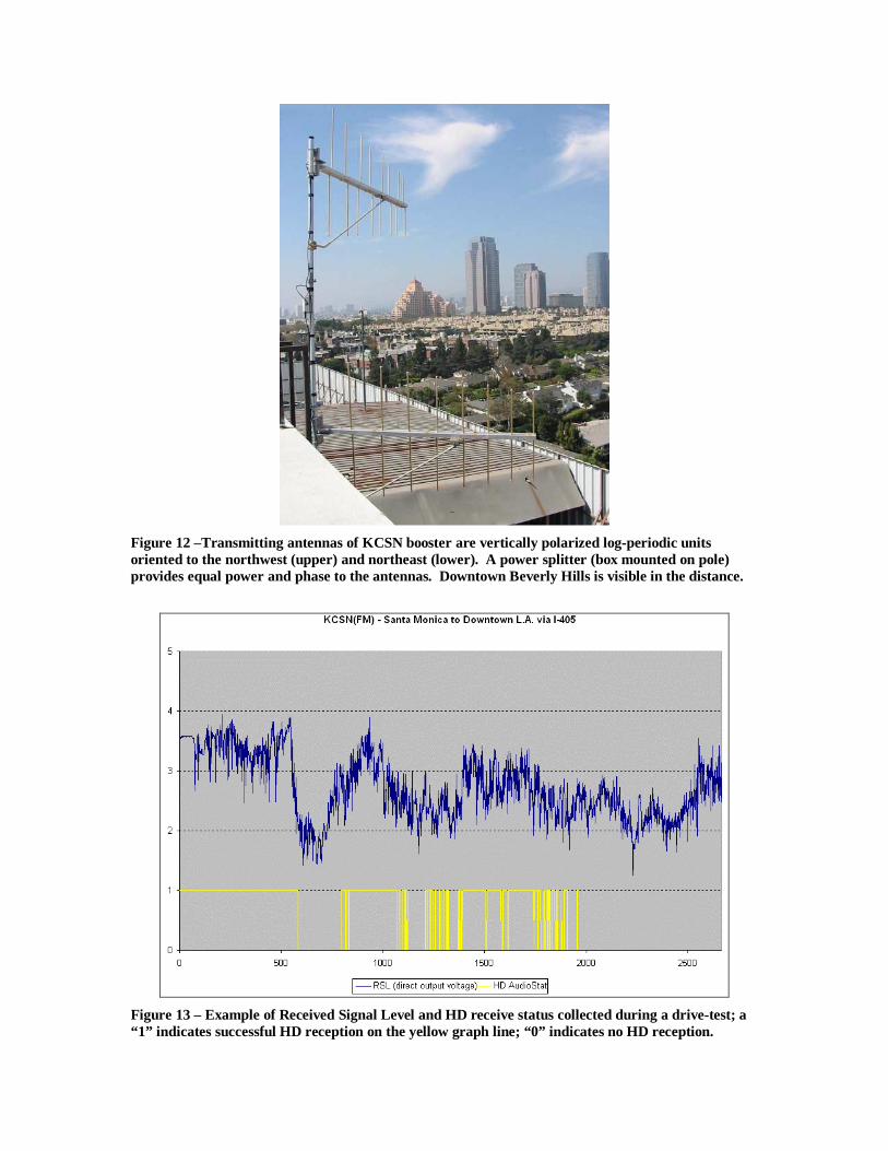
Figure 12 –Transmitting antennas of KCSN booster are vertically polarized log-periodic units oriented to the northwest (upper) and northeast (lower). A power splitter (box mounted on pole) provides equal power and phase to the antennas. Downtown Beverly Hills is visible in the distance.
Figure 13 – Example of Received Signal Level and HD receive status collected during a drive-test; a “1” indicates successful HD reception on the yellow graph line; “0” indicates no HD reception.