
Humanoid Joint State Estimation - Department of …asaran/reports/humanoid.pdf · Humanoid Joint...
6
Humanoid Joint State Estimation Chungyang Sun [email protected] Akanksha Saran [email protected] Jacob Walker [email protected] Minh Vo [email protected] Abstract Disney’s Sky Robot is a humanoid robot whose motion can be controlled using hydraulics. There are internal sensors which can give a fair estimate of the joint locations of the robot. However during fast motions, the arm creates jerks as it comes to a halt. For such motions, the internal sensors are not very accurate. We model the motion of the robot’s joints during such fast and jerky motions using external sensors to have better estimates of the robot’s motion. We use two types of external sensing - multiple cameras embedded on the robot (structure from motion) and motion capture. We demonstrate results for joint localizations obtained using these two approaches. The motion capture approach is more robust than structure from motion as found in our experiments. We further go on to model the motion control for the robot using Gaussian Process regression where the joint estimates from external sensors are used as regressor output and internal sensor data is used as regressor input. The GP estimates the joint positions within a high level of confidence. 1 Introduction Estimating the real joint locations of the humanoid robot when it is in movement is a hard problem. Given the set of commands from the controller, it is very unlikely that the robot will exactly follow such preprogram trajectory due to limitation in the robot’s hardware, especially for fast-moving action which results in vibration in the robot itself. Furthermore, these subtle effect is not measurable from the robot internal sensors. For example, the stopping vibration disrupting the sensor model when the joint stops which is not captured by the output sensor. But the stopping vibration is treated just as a part of the result of the motion but not a separate model. Hence, it is desirable to model the variance of robots arm trajectory from the sensor output over a set of arm movements. The approach is to embed cameras on the body of the humanoid and use structure from motion techniques to approximate the position of the cameras as the position of the joints. The scope of the project comprises of modeling the real trajectory of the robot. As part of a larger plan, which is to refine the control to compromise the variance of the trajectory and achieve stable dynamic movement, we provide the variance model for control. 2 Estimation of Joints 2.1 Structured from Motion Approach Our first trial is to use Structured from Motion (SfM) to estimate the pose of robot joints using the approach proposed by Takagi et al [1]. We attached several unsynchronized RGB cameras, i.e. GoPro, around the joint of the robot. We will specifically do this using a structure from motion. Given the kinematic model of the robot, if we can estimate the position and orientation of the cam- eras with respect to the robot reference frame, we can model the motion dynamics of the humanoid. 1
Transcript of Humanoid Joint State Estimation - Department of …asaran/reports/humanoid.pdf · Humanoid Joint...

Humanoid Joint State Estimation
Chungyang [email protected]
Akanksha [email protected]
Jacob [email protected]
Minh [email protected]
Abstract
Disney’s Sky Robot is a humanoid robot whose motion can be controlled usinghydraulics. There are internal sensors which can give a fair estimate of the jointlocations of the robot. However during fast motions, the arm creates jerks as itcomes to a halt. For such motions, the internal sensors are not very accurate.We model the motion of the robot’s joints during such fast and jerky motionsusing external sensors to have better estimates of the robot’s motion. We use twotypes of external sensing - multiple cameras embedded on the robot (structurefrom motion) and motion capture. We demonstrate results for joint localizationsobtained using these two approaches. The motion capture approach is more robustthan structure from motion as found in our experiments. We further go on to modelthe motion control for the robot using Gaussian Process regression where the jointestimates from external sensors are used as regressor output and internal sensordata is used as regressor input. The GP estimates the joint positions within a highlevel of confidence.
1 Introduction
Estimating the real joint locations of the humanoid robot when it is in movement is a hard problem.Given the set of commands from the controller, it is very unlikely that the robot will exactly followsuch preprogram trajectory due to limitation in the robot’s hardware, especially for fast-movingaction which results in vibration in the robot itself. Furthermore, these subtle effect is not measurablefrom the robot internal sensors. For example, the stopping vibration disrupting the sensor modelwhen the joint stops which is not captured by the output sensor. But the stopping vibration is treatedjust as a part of the result of the motion but not a separate model. Hence, it is desirable to model thevariance of robots arm trajectory from the sensor output over a set of arm movements. The approachis to embed cameras on the body of the humanoid and use structure from motion techniques toapproximate the position of the cameras as the position of the joints.
The scope of the project comprises of modeling the real trajectory of the robot. As part of a largerplan, which is to refine the control to compromise the variance of the trajectory and achieve stabledynamic movement, we provide the variance model for control.
2 Estimation of Joints
2.1 Structured from Motion Approach
Our first trial is to use Structured from Motion (SfM) to estimate the pose of robot joints usingthe approach proposed by Takagi et al [1]. We attached several unsynchronized RGB cameras, i.e.GoPro, around the joint of the robot. We will specifically do this using a structure from motion.Given the kinematic model of the robot, if we can estimate the position and orientation of the cam-eras with respect to the robot reference frame, we can model the motion dynamics of the humanoid.
1
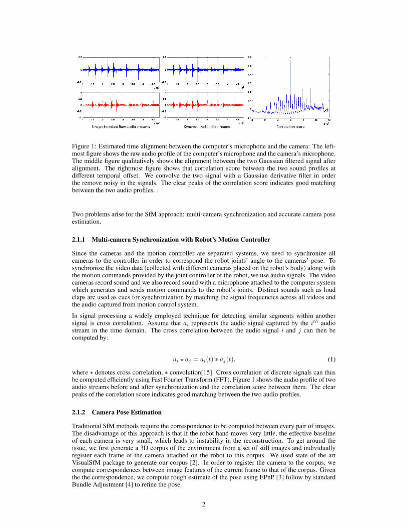
Figure 1: Estimated time alignment between the computer’s microphone and the camera: The left-most figure shows the raw audio profile of the computer’s microphone and the camera’s microphone.The middle figure qualitatively shows the alignment between the two Gaussian filtered signal afteralignment. The rightmost figure shows that correlation score between the two sound profiles atdifferent temporal offset. We convolve the two signal with a Gaussian derivative filter in orderthe remove noisy in the signals. The clear peaks of the correlation score indicates good matchingbetween the two audio profiles. .
Two problems arise for the SfM approach: multi-camera synchronization and accurate camera poseestimation.
2.1.1 Multi-camera Synchronization with Robot’s Motion Controller
Since the cameras and the motion controller are separated systems, we need to synchronize allcameras to the controller in order to correspond the robot joints’ angle to the cameras’ pose. Tosynchronize the video data (collected with different cameras placed on the robot’s body) along withthe motion commands provided by the joint controller of the robot, we use audio signals. The videocameras record sound and we also record sound with a microphone attached to the computer systemwhich generates and sends motion commands to the robot’s joints. Distinct sounds such as loudclaps are used as cues for synchronization by matching the signal frequencies across all videos andthe audio captured from motion control system.
In signal processing a widely employed technique for detecting similar segments within anothersignal is cross correlation. Assume that ai represents the audio signal captured by the ith audiostream in the time domain. The cross correlation between the audio signal i and j can then becomputed by:
ai ? aj = ai(t) ∗ aj(t), (1)
where ? denotes cross correlation, ∗ convolution[15]. Cross correlation of discrete signals can thusbe computed efficiently using Fast Fourier Transform (FFT). Figure 1 shows the audio profile of twoaudio streams before and after synchronization and the correlation score between them. The clearpeaks of the correlation score indicates good matching between the two audio profiles.
2.1.2 Camera Pose Estimation
Traditional SfM methods require the correspondence to be computed between every pair of images.The disadvantage of this approach is that if the robot hand moves very little, the effective baselineof each camera is very small, which leads to instability in the reconstruction. To get around theissue, we first generate a 3D corpus of the environment from a set of still images and individuallyregister each frame of the camera attached on the robot to this corpus. We used state of the artVisualSfM package to generate our corpus [2]. In order to register the camera to the corpus, wecompute correspondences between image features of the current frame to that of the corpus. Giventhe the correspondence, we compute rough estimate of the pose using EPnP [3] follow by standardBundle Adjustment [4] to refine the pose.
2

Figure 2: Pose estimation of the camera at the wrist joint. Due to motion blur and the rolling shuttercamera, the pose cannot be accurately estimated despite our effort make many artifical features inthe environments.
Figure 3: Motion blur and rolling shutter effect on the observed images. Despite fast camera fram-erate, accurate estimation of the camera pose is difficult.
Figure 2 shows the reconstructed 3D corpus and the pose estimation of that camera attached in theregion of the wrist. Qualitatively, while the 3D corpus captures the 3D structure of the surroundingenvironment well, the estimated poses are severely contaminated by noise. Despite fast framerate,i.e. 120fps, the recorded images contain server motion blur. Additional non-negligible effect comesfrom the rolling shutter camera where line by line scanning of the image sensor array is used. Thesecombined effects are shown in Fig 3. Recently, Kroeger et al. [5] employs Kernel Regression andnonlinear optimization to smooth out camera poses. However, since our purpose is to use SfM tocapture the possible vibration of the robot joint trajectory, no smoothing should be applied to thedata.
To sum up, due to the motion blur and the rolling shutter effect, our first trial of SfM fails.
2.2 Motion Capture
Disney Research is quipped with OptTrack Motion Capture system and utilized it to perform taskssuch as catching. In theory, it will provide a more accurate position estimation than embedded cam-era. The 3D location of markers can be resolved with millimeter accuracy, with increased accuracy
3
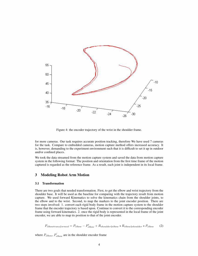
Figure 4: the encoder trajectory of the wrist in the shoulder frame.
for more cameras. Our task requires accurate position tracking, therefore We have used 7 camerasfor the task. Compare to embedded cameras, motion capture method offers increased accuracy. Itis, however, demanding to the experiment environment such that it is difficult to set it up in outdoorand/or confined places.
We took the data streamed from the motion capture system and saved the data from motion capturesystem in the following format: The position and orientation from the first time frame of the motioncaptured is regarded as the reference frame. As a result, each joint is independent in its local frame.
3 Modeling Robot Arm Motion
3.1 Transformation
There are two goals that needed transformation. First, to get the elbow and wrist trajectory from theshoulder base. It will be used as the baseline for comparing with the trajectory result from motioncapture. We used forward Kinematics to solve the kinematics chain from the shoulder joints, tothe elbow and to the wrist. Second, to map the markers to the joint encoder position. There aretwo steps involved: 1. convert each rigid body frame in the motion capture system to the shoulderframe that the encoder trajectory is based upon. Continue to convert it to the corresponding encoderframe using forward kinematics. 2. once the rigid body is represented in the local frame of the jointencoder, we are able to map its position to that of the joint encoder.
Pelbowtransformed = Pelbow − P ′elbow +Rshoulder2elbow ? Relbow2shoulder ? Pelbow (2)
where Pelbow, P′
elbow are in the shoulder encoder frame
4

Figure 5: Estimation of the elbow, where green is the true trajectory, and blue is the estimatedtrajectory.
3.2 Gaussian Process Regression
In our work, we chose Gaussian Process Regression to estimate the final joint position given thesensor outputs. We pose the joint state estimation as a regression problem, and we believe that thenon-parametric GPR is useful for this situation, given multiple predictions and the non-linearity ofthe mapping. We find that GPR is able to estimate the positions quite well from the sensor data. Theconfidence around the GPR mean is often below the vibration error, and the structure of GPR allowsus to identify the configurations where confidence of the estimation is low. Below is an example ofour estimation (blue trajectory, GP mean) against the true trajectory according to the motion capturedata (green trajectory). The second picture shows the confidence of the estimation, with hot colorsrepresenting high confidence estimations, and cool colors representing low confidence.
4 Conclusion
From the above discussions, we have come to the following conclusions. First, using GaussianProcess to predict the mean trajectory of the motion is successful for the current limited amount ofdata. Second, we have explored both SfM and motion capture methods and found that the motioncapture method is better suited for capturing and measuring fast motion. Third, for the control touse the model, we will need to get the error between the motion capture trajectory and the trajectorycalculated from encoder values.
References
[1] T. Shiratori, H. S. Park, L. Sigal, Y. Sheikh, and J. K. Hodgins, “Motion capture from body-mounted cameras,” in ACM Transactions on Graphics (TOG), vol. 30, no. 4. ACM, 2011,
5

Figure 6: This is the same trajectory as in Figure 5, except now there is an visualization of thestate estimation confidence indicated by the Gaussian Process Regression standard deviation aroundthe mean. Here, cool colors represent low confidence estimations, while hot colors represent highconfidence. In this case, where there is stopping, there is low confidence of the exact position of thejoint. Note that this is only a scaled visualization, as the actual variance of the confidence is quitelow (0.01 - 0.02), in millimeters, with only a few high outliers near the stopping points.
p. 31.[2] W. Changchang. (2011) Visualsfm. [Online]. Available: http://ccwu.me/vsfm/index.html[3] V. Lepetit, F. Moreno-Noguer, and P. Fua, “Epnp: An accurate o (n) solution to the pnp prob-
lem,” International journal of computer vision, vol. 81, no. 2, pp. 155–166, 2009.[4] B. Triggs, P. F. McLauchlan, R. I. Hartley, and A. W. Fitzgibbon, “Bundle adjustmenta modern
synthesis,” in Vision algorithms: theory and practice. Springer, 2000, pp. 298–372.[5] T. Kroeger, R. Dragon, and L. Van Gool, “Multi-view tracking of multiple targets with dynamic
cameras,” in Pattern Recognition. Springer, 2014, pp. 653–665.
6