Natural modes of Bernoulli-Euler beams with a single-edge ...

7/27/2019 Http Www.inrisk.ubc.CA Process.php File=STRUCTURAL ANALYSIS Euler Bernoulli Beams
http://slidepdf.com/reader/full/http-wwwinriskubcca-processphp-filestructural-analysis-euler-bernoulli 1/14
This document is part of the notes written by Terje Haukaas and posted at www.inrisk.ubc.ca.The notes are revised without notice and they are provided “as is” without warranty of any kind.
You are encouraged to submit comments, suggestions, and questions to [email protected].
It is unnecessary to print these notes because they will remain available online.
Euler-Bernoulli Beams
TheEuler-Bernoullibeamtheorywasestablishedaround1750withcontributionsfromLeonardEulerandDanielBernoulli.TheworkbuiltonearlierdevelopmentsbyJacob Bernoulli. However, the beam problem had been addressed even earlier.Galileoattemptedoneformulationbutmisplacedtheneutralaxis.LeonardodaVincialso seems to have addressed the problem of beam bending. The two keyassumptions in the Euler-Bernoulli beam theory are that the material is linearelastic according to Hooke’s law and that plane sections remain plane andperpendiculartotheneutralaxisduringbending.ThelatterissometimesreferredtoasNavier’shypothesis.Incontrast,Timoshenkobeamtheory,whichiscoveredinanotherdocument,relaxestheassumptionthatthesectionsremainperpendicular
totheneutralaxis,thusincludingsheardeformation.Inthefollowing,thegoverningequations are established, followed by the formulation and solution of thedifferential equation. Thereafter, the computation of stresses and cross-sectionconstantsisdescribed.
Anumberofsignconventionsareadoptedinthefollowing:
§ The z -axisisincreasesupward§ Displacementw ispositiveinthedirectionofthe z -axis

7/27/2019 Http Www.inrisk.ubc.CA Process.php File=STRUCTURAL ANALYSIS Euler Bernoulli Beams
http://slidepdf.com/reader/full/http-wwwinriskubcca-processphp-filestructural-analysis-euler-bernoulli 2/14
Terje Haukaas University of British Columbia www.inrisk.ubc.ca
Euler-Bernoulli Beams Page 2
§ Distributedloadq z ispositivewhenitactsinthedownwarddirection§ Clockwiseshearforceispositive§ Bendingmomentthatimposestensionatthebottomofahorizontalbeam
elementispositive§ Counter-clockwiserotation θ ispositivesothatitcanbeinterpretedasthe
slopeofthedeformedbeamelement§ Tensilestressesandstrainsarepositive,compressionisnegative
EquilibriumThe equilibrium equations are obtained by considering equilibrium in the x -directionfortheinfinitesimalbeamelementinFigure1.Noticethatthedistributedload,q,actsinthedownwarddirection,whilethe z -axisisintheupwarddirection.Thenotationq z isemployedinotherdocumentstoidentifythecasewherepositiveloadactsinthepositive z -direction.
Figure1:Equilibriumforinfinitesimallysmallbeamelement.
Verticalequilibriumyields:
q = !
dV
dx (1)
Momentequilibriumabouttherightmostedgeyields:
V =dM
dx (2)
InEq.(2)itisnotedthat“second-orderterms”areneglected.Thisessentiallymeansthattermswithdx 2(themultiplicationofanexceedinglysmallvaluebyitself)areconsideredapproximatelyequaltozero.
SectionIntegrationIntegrationofaxialstressesoverthecross-section:
M = !" # z d A
A
$ (3)
d x
q
V M M+dM V+dV

7/27/2019 Http Www.inrisk.ubc.CA Process.php File=STRUCTURAL ANALYSIS Euler Bernoulli Beams
http://slidepdf.com/reader/full/http-wwwinriskubcca-processphp-filestructural-analysis-euler-bernoulli 3/14
Terje Haukaas University of British Columbia www.inrisk.ubc.ca
Euler-Bernoulli Beams Page 3
wheretheminussignappearsbecauseitiscompressive(negative)stressesinthepositive z -axisdomainthatgivesapositivebendingmoment,i.e.,bendingmomentwithtensionatthebottom.Figure2isintendedtoexplainthisfurther.
Figure2:ThereasonfortheminussigninEq.(3).
MaterialLawThemateriallawthroughoutlinearelastictheoryisHooke’slaw:
! = E "# (4)
Inthecontextoftwo-dimensionaltheoryofelasticity,theuseofEq.(4)impliesa“planestress”materiallaw.Itimpliesthatthereiszerostress,i.e.,aironthesidesofthebeam.Thealternative“planestrain”versionofthetwo-dimensionalHooke’slawismoreappropriateincaseswherethebeamisonlyastripofalongrectangularplatethatissupportedalongthetwolongedges.Inthatcasethestrainisrestrainedinthe y -direction:
! yy =
" yy
E #$ %
" xx
E = 0 & " yy = $ %" xx
(5)
Which,substitutedintothemateriallawinthe x -directionyields:
! xx =
" xx
E
#$
" yy
E
=
" xx
E
#$
$ %" xx( )
E
=
" xx
E
(1#$ 2) & "
xx =
E
1#$
2%!
xx (6)
All the derivations and results in the following are based on the material lawσ xx =E .ε xx from Eq. (4). However, the plain strain version is easily introduced byreplacingtheYoung’smodulus,E ,inanyequationbyE /(1-ν 2).
• Positive tension stress
• Negative z -values
x
z • Negative compression stress
• Positive z -values
Minus sign is cross-section
integral is necessary to get
positive bending moment
M M

7/27/2019 Http Www.inrisk.ubc.CA Process.php File=STRUCTURAL ANALYSIS Euler Bernoulli Beams
http://slidepdf.com/reader/full/http-wwwinriskubcca-processphp-filestructural-analysis-euler-bernoulli 4/14
Terje Haukaas University of British Columbia www.inrisk.ubc.ca
Euler-Bernoulli Beams Page 4
KinematicsThe relationship between the axial strain and the transversal displacement of abeamelementissought.Itisfirstrecognizedthatbendingdeformationessentiallyimplies shortening and lengthening of “fibres” in the cross-section. Fibres on thetensionsideelongate,whilefibresonthecompressionsideshorten.
Thestartingpointfortheconsiderationsistolinktheaxialstraintothechangeoflength of the imaginative fibres that the cross-section is made up of. The sameconsiderationasinkinematicsoftrussmembers,namelythatstrainis“elongationdividedbyoriginallength”yields:
! =
du
dx
(7)
Next, the axial displacement u is related to the rotation of the cross-section. Inparticular,considertheinfinitesimalrotationdθ oftheinfinitesimallyshortbeamelementinFigure3.Inpassing,itisnotedthatdθ isequaltothecurvature, κ .Under
theassumptionthatplanesectionsremainplaneandperpendiculartotheneutralaxisduringdeformation,eachfibreinthecross-sectionchangelengthproportionaltoitsdistancefromtheneutralaxis.
Figure3:Navier’shypothesisforbeambending.
The amount of shortening orelongation depends upon the rotationof the cross-section.AgeometricalconsiderationoftoFigure3showsthattheshorteningandlengthening,i.e.,axialdisplacement,ofeachinfinitesimallyshortfibreis
du = !d" # z (8)
Finally,therotationθ isrelatedtothetransversaldisplacement.Forthispurpose,
considertwopointsonabeamthatisd x apart,asshowninFigure4.Therelativedisplacement is dw , which is measure positive upwards. Consequently, ageometricalconsiderationofFigure4showsthat:
tan(! ) =
dw
dx"! (9)
wheretheequationissimplifiedbyassumingthatthedeformationsaresufficientlysmallsothattan(θ )≈θ .
z
d!
x, u
z, w

7/27/2019 Http Www.inrisk.ubc.CA Process.php File=STRUCTURAL ANALYSIS Euler Bernoulli Beams
http://slidepdf.com/reader/full/http-wwwinriskubcca-processphp-filestructural-analysis-euler-bernoulli 5/14
Terje Haukaas University of British Columbia www.inrisk.ubc.ca
Euler-Bernoulli Beams Page 5
dx
dw
!
!
Figure4:Rotationofthecross-sectionofabeamelement.
Bycombiningequations,thekinematicequationforbeammembersisobtained:
! = "d
2
w
dx2# z (10)
This expression implies an approximation of the exact curvature of the beam.Mathematically,curvatureisdefinedas
! "
1
R (11)
whereRistheradiusofcurvatureofthebeam.IntheEuler-Bernoullibeamtheorythatispresentedhere,thecurvatureisapproximatedby
! "d #
dx"
d 2w
dx2 (12)
Notice that there are two approximation signs. The first alludes to the fact thatdifferentiationiscarriedoutwithrespecttothe x -axis.Unlessthedeformationsarenegligiblethisisinaccurate;differentiationshouldbecarriedoutwithrespecttothe“s-axis”thatfollowsthecurvingbeamaxis.ThesecondapproximationisduetoEq.(9).Fromthatequationitisobservedthattheaccurateexpressionforθ is:
! = tan
"1 dw
dx
# $ %
& ' ( (13)
Ifthisexpressionwas utilizedinthederivationsabovethen thedifferentiationoftheinversetan-functionyields
! "d #
dx=
d 2w
dx2
$ % &
' ( )
1+dw
dx
$ % &
' ( ) 2$
% &'
( )
(14)
7/27/2019 Http Www.inrisk.ubc.CA Process.php File=STRUCTURAL ANALYSIS Euler Bernoulli Beams
http://slidepdf.com/reader/full/http-wwwinriskubcca-processphp-filestructural-analysis-euler-bernoulli 6/14
Terje Haukaas University of British Columbia www.inrisk.ubc.ca
Euler-Bernoulli Beams Page 6
which reduces to the expression in Eq. (12) when the slope dw /dx is small.However, the curvature expression in Eq. (14) is still approximate because thedifferentiationiscarriedoutwithrespecttothe x -axisandnotthebeamaxis.Frommathematics,theexactcurvatureexpressionis:
! =
d 2w
dx2
" # $
% & '
1+dw
dx
" # $
% & ' 2"
# $%
& '
3
2
(15)
DifferentialEquationThegoverningdifferentialequationforbeammembersisobtainedbycombiningtheequationsforequilibrium,sectionintegration,materiallaw,andkinematics:
q = ! dV dx
= ! d 2
M dx2
= d 2
dx2" # z d A
A$
=
d 2
dx2E #% # z d A
A
$ = !d 2
dx2E #
d 2w
dx2# z2 d A
A
$
= ! EI d
4w
dx4
(16)
wherethemodulusofelasticityisassumedconstantoverthecross-sectionandthemomentofinertiaisdefined:
I =
z
2d A
A! (17)
GeneralSolutionAlthoughsolvingthedifferentialequationisnotpartoftypicalstructuralanalysisitis instructive to study its solution for simple reference cases. In particular, thesolutionofthedifferentialequationisthestartingpointfortheselectionofshapefunctions in the finite element method. Those shape functions are oftenapproximate,whilethesolutionofthedifferentialequationrevealstheexactshapewhenthememberdeforms.Thegeneralsolutionofthedifferentialequationreveals
whetherthefiniteelementshapefunctionsareexactornot.Forbeammembers,thegeneralsolutionofthedifferentialequationisobtainedbyintegratingfourtimes:
w( x) =1
24!
q z
EI ! x
4+C
1! x
3+C
2! x
2+C
3! x +C
4 (18)
Given a uniform distributed load q z , the displaced shape is a fourth orderpolynomial. Without any distributed load, the displacement shape of a beammember is a third-order polynomial. To obtain the solution for a specific beam

7/27/2019 Http Www.inrisk.ubc.CA Process.php File=STRUCTURAL ANALYSIS Euler Bernoulli Beams
http://slidepdf.com/reader/full/http-wwwinriskubcca-processphp-filestructural-analysis-euler-bernoulli 7/14
Terje Haukaas University of British Columbia www.inrisk.ubc.ca
Euler-Bernoulli Beams Page 7
problem,boundaryconditionsarespecified.Toprescribearotation,shearforce,orbending moment, the following equations are useful, obtained by combining thegoverningequationsthatareestablishedearlier:
! =dw
dx (19)
M = EI d
2w
dx2 (20)
V = EI d
3w
dx3 (21)
As an illustration of the solution to the differential equation for beam bending,Figure5showsplotsofw ( x ),θ ( x ),M ( x ),andV ( x )forasimplysupportedbeamwithuniformlydistributedload.Theillustrationismadewithq z =L=EI =1.
Figure5:Exampleofresponsefunctionsforbeamelement.
With reference to Figure 5, notice that the displacement w ( x ) is negative, i.e.,
downwardsandthatθ ( x )correctlyshowsthattheslopeisnegativeleftofthemid-span. Furthermore, notice that the plots of M ( x ) and V ( x ) are identical to therespective section force diagrams, with one exception: plotting M ( x ) yields adiagramdrawnonthecompressionside,whileinthesenotesthebendingmomentdiagramsareconsistentlydrawnonthetensionside.

7/27/2019 Http Www.inrisk.ubc.CA Process.php File=STRUCTURAL ANALYSIS Euler Bernoulli Beams
http://slidepdf.com/reader/full/http-wwwinriskubcca-processphp-filestructural-analysis-euler-bernoulli 8/14
Terje Haukaas University of British Columbia www.inrisk.ubc.ca
Euler-Bernoulli Beams Page 8
Cross-sectionParametersThe only cross-section constant in fundamental 2D beam theory is the cross-sectionalmomentofinertia,I ,definedinEq.(17).Intheformula, z isthedistancefrom the neutral axis of the cross-section. For simple cross-sections, mostprominentlytherectangularonewithwidthbandheighth,theintegralisevaluated
analytically:
I = b ! z2d z
"h/2
h/2
# =
b !h3
12 (22)
Formorecomplicatedcross-sectionsthefollowingproceduremaybehelpful:
1. Determinethelocationoftheneutralaxis.Forhomogeneouscross-sections,theneutralaxispassesthroughthecentroidofthecross-section.Inotherwords,whenthecoordinate z has itsorigin at the centroid then the staticmoment∫ z d Aiszero.Inpractice,firstselectareferenceaxisinthecross-sectionthatisparalleltotheneutralaxiasandlet z odenoteitsdistancetothe
trueneutralaxis.Furthermore,let z idenotethedistancefromthearbitrarilyselected axis to the centroid of each sub-area, Ai that the cross-sectionconsistsof.Thedistancetothetrueneutralaxisisdeterminedfrom:
A· zo= A
i· z
i
All parts of thecross-section
! " zo=
Ai· z
i! A
(23)
2. Determine the local moment of inertia, I i, of each sub-area of the cross-sectionaboutthelocalcentroidaxisofthatpart.
3. Addcontributionstotheglobalmomentofinertiafromeachcross-section
partaccordingtoSteiner’sformula: I = I
i+ z
i
2· A
i
All parts of thecross-section
! (24)
where z iisthedistancefromtheneutralaxisoftheentirecross-sectiontothecentroidofthepart.
PrincipalAxes
Thisdocumentdescribesbendingaboutoneaxis,i.e.,bendingof2Dbeams.Withthemost common cross-sections it is straightforward to understand which cross-sectionaxisthebeamwillbendaround.Forexample,adouble-symmetriccross-
section bends around the two symmetry-axes. However, additional analysis isnecessaryforgeneralasymmetriccross-sectionstodeterminethe“principalaxes,”i.e., the bending axes of the cross-section. As a starting point, suppose two axesdirections y and z are arbitrary selected; they originate in the centroid but theygenerallydonotcoincidewiththeprincipalaxes.Thetotalaxialstrainatalocationofthecross-sectionisexpressedinthefollowingextendedversionofEq.(10):

7/27/2019 Http Www.inrisk.ubc.CA Process.php File=STRUCTURAL ANALYSIS Euler Bernoulli Beams
http://slidepdf.com/reader/full/http-wwwinriskubcca-processphp-filestructural-analysis-euler-bernoulli 9/14
Terje Haukaas University of British Columbia www.inrisk.ubc.ca
Euler-Bernoulli Beams Page 9
! = ! o "d
2v
dx2# y "
d 2w
dx2# z (25)
Fromthisstrain,themateriallawinEq.(4)providesthestress,andthestressisintegrated byEq. (3) toobtain the following expression for the bendingmoment
aboutthey-axis:
M = ! E "# o " z d A A
$ + E "d
2v
dx2" y " z d A A
$ + E "d
2w
dx2" z
2d A
A
$ (26)
Thefirstintegralvanishesbecause z originatesatthecentroid,whilethelasttermistheordinarybendingmomentfromEq.(20).Asaresult,Eq.(26)isrewrittenas:
M = EI yz !
d 2v
dx2+ EI !
d 2w
dx2 (27)
wherethe“productofinertia,”I yz ,hasbeendefinedas:
I yz = y ! z d A A" (28)
ItisrelativelystraightforwardtoestablishformulasforI yz andcomputestressesintermofI yz ,etc.However,itisalsoalwayspossibletorotatetheaxissystemsothatI yz is zero; then the axis system is referred to as the principal axes. This isadvantageousbecausetheelementaryformulasforbeambendingremainvalid.
(Materialtobeaddedhere.)
Stresses
AlthoughtheEuler-Bernoullibeamtheoryisformulatedintermsofaxialstress,σ ,beam bending involves both axial and shear stresses. The axial stress is directlyrelatedtothebendingmoment,whiletheshearstressisdirectlyrelatedtotheshearforceasdescribedshortly.Onewayofobtaininganexpressionforaxialstressintermsofthebendingmomentistocombinemateriallawandkinematicsequations,whichyields:
! = " E #d
2w
dx2# z (29)
Then substitute the differential equation without equilibrium equations, i.e., Eq.(20),toobtain:
! = "
M
I # z (30)
It is noted that a positive bendingmoment, i.e., tension at the bottom, correctlyyieldsnegativestressesatthetop,i.e.,compression,where z ispositive.Thisisthereason for theminussign inEq.(30),whichalso correctly givespositive tensionstresses at the bottom when a positive moment acts on the cross-section. In
7/27/2019 Http Www.inrisk.ubc.CA Process.php File=STRUCTURAL ANALYSIS Euler Bernoulli Beams
http://slidepdf.com/reader/full/http-wwwinriskubcca-processphp-filestructural-analysis-euler-bernoulli 10/14
Terje Haukaas University of British Columbia www.inrisk.ubc.ca
Euler-Bernoulli Beams Page 10
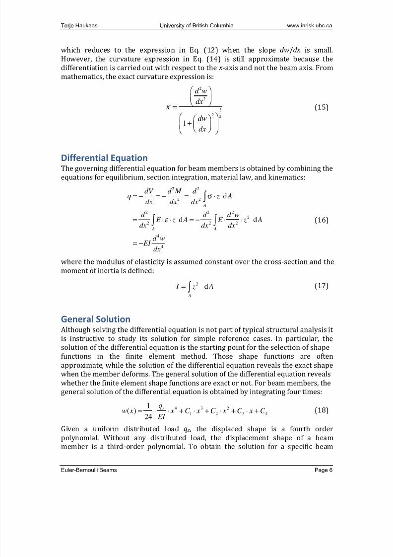
summary, the beam theory presented in this documentconsists of the governingequationsshowninFigure6.
Figure6:GoverningequationsinEuler-Bernoullibeamtheory.
ShearStressandShearCentreforOpenCross-sections
When approaching shear stresses from bending, an anomaly in Euler-Bernoullibeam theory is first noted. The theory is based on the assumption that planesections remain plane and perpendicular to the neutral axis. In otherwords, the
onlystrainthattakesplaceistheaxialshorteningorelongationofthefibresinthecross-section.Effectively,thispreventsshearstrain.Withnoshearstrainthereisnoshearstress,whichaddsuptozeroshearforce.Inotherwords,theshear forceisnotpartofthetheory.Thisisananomaly,becauseshearforcewilldevelopeveninsimple beams that are subjected to transversal load. Theanomaly is customarilyaddressedbyrecoveringtheshearforcebyequilibriumoncethebendingmomentiscomputed.Infact,accordingtoEq.(2)theshear forceisequaltothederivativeofthe bending moment; this is the equation that recovers the shear force. AnotherdocumentonTimoshenkobeamtheorydescribesanapproachtofurtherextendthebeamtheorytoincludedeformationduetoshearforces.
Toobtainexpressionsfortheshearstress,τ ,intermsoftheshearforce,V,considertheinfinitesimallyshortbeamelementinFigure7.Furthermore,considera“cut”inthecross-sectionandletqsdenotethe“shearflow”atthatlocation.
! "
q
! = "
d 2w
dx2# z
! = E "#
! = "
M
I # z
M = !" # z d A
A
$
q = ! EI d
4w
dx4
q = !dV
dx
V =dM
dx
M = EI d
2w
dx2
w
M

7/27/2019 Http Www.inrisk.ubc.CA Process.php File=STRUCTURAL ANALYSIS Euler Bernoulli Beams
http://slidepdf.com/reader/full/http-wwwinriskubcca-processphp-filestructural-analysis-euler-bernoulli 11/14
Terje Haukaas University of British Columbia www.inrisk.ubc.ca
Euler-Bernoulli Beams Page 11
Figure7:Shearflowbyequilibriumofinfinitesimalbeamelement.
Theshearflowistheforceperunitlengthofthebeamthatensuresequilibriumwiththeaxialstresses,whicharegreaterononesidethantheotherduetodM :
qs !dx = d " dA As
# =
dM
I ! z dA
As
# (31)
where Asisthecross-sectionalareaoutsidethecut.GiventhatV=dM/dx ,thisyields
qs =
V
I !S (32)
where
S = zdA
As
! (33)
Theshearstressiscalculatedbydistributingtheshearflowoverthethickness,t ,ofthecross-sectionattheparticularlocation:
! =V "S
I " t (34)
For example, for a rectangular cross-section themaximum shear stress is at theneutralaxis,withvalueequalto
! =
3
2 "
V
A (35)
Theshearcentreofacross-section,sometimescalledthecentreoftwist,isthepointwheretheresultantoftheshearforcemustacttoavoidrotationofthecross-section.Thecoordinatesoftheshearcentrearedenotedby y scand z sc,andthereareseveraltechniques to determine them. The simplest case is double-symmetric cross-sections;forthesecross-sectionstheshearcentrecoincidewiththecentroid.Infact,ifacross-sectionhasanaxisofsymmetrythentheshearcentreislocatedonthis
d x
V M
M+dM
V+dV
Axial stresses
Shear stresses
(“shear flow”)

7/27/2019 Http Www.inrisk.ubc.CA Process.php File=STRUCTURAL ANALYSIS Euler Bernoulli Beams
http://slidepdf.com/reader/full/http-wwwinriskubcca-processphp-filestructural-analysis-euler-bernoulli 12/14
Terje Haukaas University of British Columbia www.inrisk.ubc.ca
Euler-Bernoulli Beams Page 12
axis.Forgeneralcross-sections,oneapproachtodetermine y scand z scisdescribedinthedocumentonwarpingtorsion,wherethe“omegadiagram”isutilized.However,asomewhatsimplerapproach,whentheconsiderationofwarpingtorsionisoffthetable,isofferedhere.Theprincipleissimple;bydefinition,themomentoftheshearflowabouttheshearcentremustbezero.Thisleadstothefollowingprocedureto
determine the coordinatesofthe shearcentre,provided y and z aretheprincipalaxesthroughthecentroidofthecross-section:
1. Selectanarbitrarypointas trialshear centre,andlet y scand z scdenotethecoordinatesoftheshearcentrerelativetothecentroid;inotherwords,let y scand z scdenotethedistancesfromthecentroidtotheshearcentre
2. InaccordancewithEq.(32),determinetheshearflowinthecross-sectionduetoashearforceinthe z -direction
3. WritetheequationthatexpressesthemomentoftheshearflowinItem2aboutthetrialshearcentre;ingeneral,both y scand z scwillappearinthisexpression
4. SimilartoItem2,determinetheshearflowinthecross-sectionduetoashearforceinthe y -direction
5. SimilartoItem3,writetheequationthatexpressesthemomentoftheshearflowinItem4aboutthetrialshearcentre
6. SettheequationsfromItems3and5bothequaltozeroandsolvethesetwoequationsforthetwounknowns y scand z sc
Onlyonemomentequation isneededfor single-symmetric cross-sections; inthatcasestheproceduresimplifiesto:
1. Selectanarbitrarypointalong thesymmetryaxisastrial shearcentre,andletedenotethedistancefromthecentroidtothatpoint
2. InaccordancewithEq.(32),determinetheshearflowinthecross-sectionduetoashearforceinthedirection perpendicular totheaxisofsymmetry
3. WritetheequationthatexpressesthemomentoftheshearflowinItem2aboutthetrialshearcentre;ewillappearinthisexpression
4. SettheequationfromItems3equaltozeroandsolvefore
ShearStressandShearCentreforClosedCross-sections
The determinationof shearstressandshear centre for closed cross-sections, i.e.,cross-sectionswithcell,canbeapproachedintwoways.Inthefirstapproach,theshear centre coordinates are first determined, using the “omega diagram” asdescribedinthedocumentonwarpingtorsion.Next,a“cut”inthecross-sectionismadetoyieldanopencross-section;thenewcoordinate s,whichtracesthecross-sectionaroundthecell,originatesatthecut.Theunknownshearflowatthecutisdenotedqo,andtheshearflowatallotherlocationsaredeterminedrelativetothisvalueinaccordancewithEq.(32):
q = qo+V
I !S (36)

7/27/2019 Http Www.inrisk.ubc.CA Process.php File=STRUCTURAL ANALYSIS Euler Bernoulli Beams
http://slidepdf.com/reader/full/http-wwwinriskubcca-processphp-filestructural-analysis-euler-bernoulli 13/14
Terje Haukaas University of British Columbia www.inrisk.ubc.ca
Euler-Bernoulli Beams Page 13
Onceqisdeterminedatalllocationsofthecross-section,themomentoftheshearflowabouttheshearcentreiscomputed:
T = q !hds!" = qo !hds!" +V
I !S !hds!" (37)
wheretheintegralsaremadearoundthecell,andh(s)isthedistancefromtheshearcentre to the tangent line of the cross-section at s. By definition the moment,T ,abouttheshearcentremustbezero,andsolvingforqoyields:
qo= !
V
I "
S "hds!# hds!#
= !V
2 " Am " I " S "hds!# (38)
wherethelastequalityexpressesthattheintegralof haroundthecross-sectionistwicethecellarea, Am.Havingthevalueofqo,theshearflowisdeterminedatotherlocationsbyEq.(36).Thesecondapproachtodeterminetheshearflowandshearcentreinclosedcross-sectionsentailsdeterminingtheshearcentreattheend.Also
this approach introduces a cut in the cross-section, but now compatibility isconsideredinsteadofmomentequilibrium.Tothisend,considerFigure8.
Figure8:Twocontributionstoshearstrain.
Figure 8 illustrates the two following contributions to shear strain in aninfinitesimalelementofthecross-section:
! = ! 1+ !
2=
du
ds+d "
dx#h (39)
whereφ istherotationofthecross-section.Materiallawstatesthat:
h
dx
! 1
d !
ds
! 2
du

7/27/2019 Http Www.inrisk.ubc.CA Process.php File=STRUCTURAL ANALYSIS Euler Bernoulli Beams
http://slidepdf.com/reader/full/http-wwwinriskubcca-processphp-filestructural-analysis-euler-bernoulli 14/14
Terje Haukaas University of British Columbia www.inrisk.ubc.ca
Euler-Bernoulli Beams Page 14
! ="
G=
q
G # t (40)
andcombinationofEqs.(39)and(40)yields
du =q
G!t !ds "
d #
dx!h !ds (41)
Integrationaroundthecellyieldsthetotal“gapopening”duetothecut:
u =q
G ! t ds!" #
d $
dx!hds!" (42)
Toensurecompatibility,thisgapopeningmustbezero:u=0.Fromthatequationitisofinteresttosolvefor d φ /dxbecausethecross-sectionshouldnotrotateduetoshearforce:
d !
dx=
q
G " t ds!#
hds!# =
q
G " t ds!#
2 Am
= 0
(43)
Eq.(36)providestheexpressionfortheshearflow,q,whichyields:
qo
G ! t ds!" +
V !S
I !G ! t ds!" = 0 (44)
Solvingforqoyields:
qo = !
V
I "
S
G " t ds!#
1
G " t ds!
#
(45)
Whenthematerialishomogeneous,theexpressionsimplifiesto:
q
o =!V
I "
S
t ds!#
1
t ds!#
(46)
Havingthevalueofqo,theshearflowisdeterminedatotherlocationsbyEq.(36).