
HPS Products Series 423 I-MAG - John Morris Scientific · 2016-08-02 · 1 I-MAG® Sensor 1 HPS®...
26
HPS ® Products Series 423 I-MAG ® Cold Cathode Ionization Vacuum Sensor OPERATION AND MAINTENANCE MANUAL
Transcript of HPS Products Series 423 I-MAG - John Morris Scientific · 2016-08-02 · 1 I-MAG® Sensor 1 HPS®...

HPS® ProductsSeries 423 I-MAG®
Cold Cathode Ionization
Vacuum Sensor
OPERATION ANDMAINTENANCE MANUAL


Cold Cathode Ionization Vacuum Sensor
HPS® ProductsSeries 423 I-MAG®
Cold Cathode IonizationVacuum Sensor
August 2009PART #104230020 REV. B3

Cold Cathode Ionization Vacuum Sensor
Part # 10423000X
Serial # __ __ __ __ __ __
Please fill in these numbers and havethem readily available when calling forservice or additional information.(The part number can be found on yourpacking slip, and both the part numberand serial number are located on thebottom side of the housing.)
© 1999 by MKS Instruments, Inc., HPS® Products Inc., All rights reserved.
ALCONOX is a registered trademark of Alconox, Inc.IgniTorr is a trademark of MKS Instruments, Inc., HPS® Products Inc.Inconel is a registered trademark of Inco Alloys International, Inc.Scotch-Brite is a trademark of 3M.SensaVac is a registered trademark of MKS Instruments, Inc.
For more information or literature, contact:
MKS Instruments, Inc., HPS® Products Inc.5330 Sterling DriveBoulder, CO 80301 USA
Phone: 303-449-9861800-345-1967
FAX: 303-442-6880

Cold Cathode Ionization Vacuum Sensor
Table of Contents
Table of Contents
Package Contents ..................................................................... 1
Safety Information...................................................................... 2
Symbols .................................................................................................. 2Symbols Used in this Manual (English) .............................................. 2Symboles utilisés dans ce manuel (Français) ..................................... 3In dieser Betriebsanleitung vorkommende Symbole (Deutsch) ........... 4Símbolos Usados en el Manual (Español) ........................................... 5English ................................................................................................ 6Français .............................................................................................. 6Español ............................................................................................... 6
Safety Precautions .................................................................... 6
Deutsch ............................................................................................... 6
Specifications ............................................................................ 7
Feature Locations...................................................................... 8
About the HPS® Series 423 I-MAG® Sensor ............................. 9
Installing and Using the Series 423 I-MAG® Sensor ................ 10
Locating and Orienting the Sensor .........................................................10Connecting the Sensor ...........................................................................10Starting the Sensor ................................................................................10Operating the Sensor .............................................................................11Preparing for Bakeout .............................................................................11
Maintaining the Series 423 IMAG® Sensor .............................. 12
Contamination of the Sensor ..................................................................12Disassembly ..........................................................................................12Cleaning .................................................................................................13Assembly ...............................................................................................13

Cold Cathode Ionization Vacuum Sensor
Accessories / Spare Parts ....................................................... 16
Product Warranty ..................................................................... 17
NOTES .................................................................................... 18

1Cold Cathode Ionization Vacuum Sensor
Package Contents
Before unpacking your Series 423 I-MAG® Cold Cathode Ionization VacuumSensor, check all surfaces of the packing material for shipping damage.
Please be sure that your Series 423 I-MAG® Sensor package containsthese items:
1 I-MAG® Sensor
1 HPS® Series 423 I-MAG® Cold Cathode Ionization VacuumSensor User's Guide.
If any items are missing from the package, call HPS® CustomerService at 1-303-449-9861 or 1-800-345-1967.
Cables are required for connecting the I-MAG® Sensor to its controller but aresold separately. Please refer to page 14 for necessary ordering information.
Inspect the I-MAG® Sensor for visible evidence of damage during shipment.If it has been damaged, notify the carrier immediately. Keep allshipping materials and packaging for claim verification. Do not returnthe product to HPS®.
22 Cold Cathode Ionization Vacuum Sensor
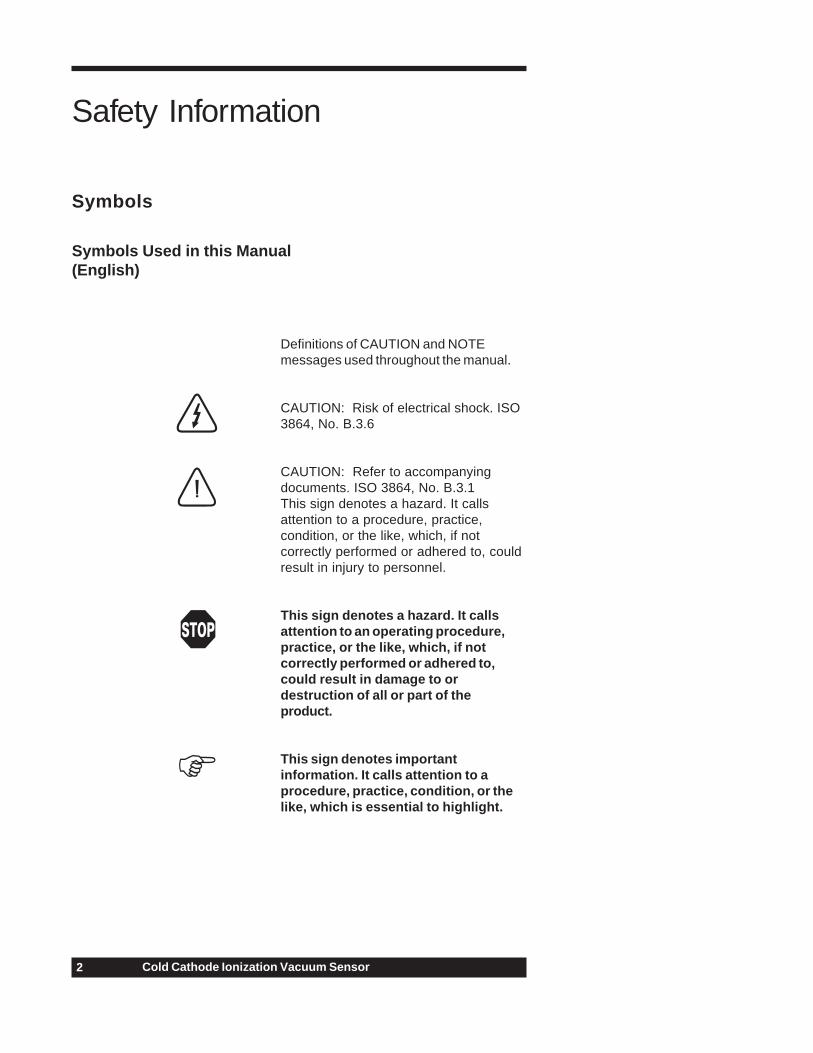
Definitions of CAUTION and NOTEmessages used throughout the manual.
CAUTION: Risk of electrical shock. ISO3864, No. B.3.6
CAUTION: Refer to accompanyingdocuments. ISO 3864, No. B.3.1This sign denotes a hazard. It callsattention to a procedure, practice,condition, or the like, which, if notcorrectly performed or adhered to, couldresult in injury to personnel.
This sign denotes a hazard. It callsattention to an operating procedure,practice, or the like, which, if notcorrectly performed or adhered to,could result in damage to ordestruction of all or part of theproduct.
This sign denotes importantinformation. It calls attention to aprocedure, practice, condition, or thelike, which is essential to highlight.
Symbols Used in this Manual(English)
Safety Information
Symbols

3Cold Cathode Ionization Vacuum Sensor
Symboles utilisés dans cemanuel (Français)Définition des indications ATTENTION etREMARQUE utilisées dans ce manuel.
ATTENTION: Risque de secousseélectrique. ISO 3864, No. B.3.6
ATTENTION: Se reporter à ladocumentation. ISO 3864, No. B.3.1L’indication signale un danger potentiel.Elle est destinée à attirer l’attention surune procédure, une utilisation, unesituation ou toute autre chose présentantun risque de blessure en cas d’exécutionincorrecte ou de non-respect desconsignes.
L’indication signale un dangerpotentiel. Elle est destinée à attirerl’attention sur une procédure, uneutilisation, une situation ou toute autrechose présentant un risqued’endommagement ou de dégât d’unepartie ou de la totalité de l’appareil encas d’exécution incorrecte ou de non-respect des consignes.
L’indication REMARQUE signale desinformations importantes. Elle estdestinée à attirer l’attention sur uneprocédure, une utilisation, unesituation ou toute autre choseprésentant un intérêt particulier.

44 Cold Cathode Ionization Vacuum Sensor
Definition der mit VORSICHT! undHINWEIS überschriebenen Abschnitte indieser Betriebsanleitung.
VORSICHT! Stromschlaggefahr!ISO 3864, Nr. B.3.6
VORSICHT! Bitte Begleitdokumentelesen! ISO 3864, Nr. B.3.1Das Symbol VORSICHT! weist auf eineGefahrenquelle hin. Es macht auf einenArbeitsablauf, eine Arbeitsweise, einenZustand oder eine sonstige Gegebenheitaufmerksam, deren unsachgemäßeAusführung bzw. UngenügendeBerücksichtigung zu Körperverletzungführen kann.
Das Symbol VORSICHT! weist auf eineGefahrenquelle hin. Es macht aufeinen Bedienungsablauf, eineArbeitsweise oder eine sonstigeGegebenheit aufmerksam, derenunsachgemäße Ausführung bzw.Ungenügende Berücksichtigung zueiner Beschädigung oder Zerstörungdes Produkts oder von Teilen desProdukts führen kann.
Das Symbol HINWEIS weist auf einewichtige Mitteilung hin, die auf einenArbeitsablauf, eine Arbeitsweise, einenZustand oder eine sonstigeGegebenheit von besondererWichtigkeit aufmerksam macht.
In dieser Betriebsanleitungvorkommende Symbole(Deutsch)

5Cold Cathode Ionization Vacuum Sensor
Definiciones de los mensajes dePRECAUCIÓN y OBSERVACIÓNusados en el manual.
PRECAUCIÓN: Riesgo de descargaeléctrica. ISO 3864, N.° B.3.6
PRECAUCIÓN: Consultar losdocumentos adjuntos. ISO 3864, N.°B.3.1 Esto símbolo indica un riesgo.Pone de relieve un procedimiento,práctica, condición, etc., que, de norealizarse u observarse correctamente,podría causar lesiones a los empleados.
Esto símbolo indica un riesgo. Ponede relieve un procedimiento, práctica,etc., de tipo operativo que, de norealizarse u observarse correctamente,podría causar desperfectos alinstrumento, o llegar incluso a causarsu destrucción total o parcial.
Esto símbolo indica información deimportancia. Pone de relieve unprocedimiento, práctica, condición,etc., cuyo conocimiento resultaesencial.
Símbolos Usados en el Manual(Español)

66 Cold Cathode Ionization Vacuum Sensor
English
Safety Precautions
High voltages are present in the Sensor during operation.
High voltage is present in the cable and the Sensor when a controller isturned on.
Danger de haute tension.
Une haute tension est présente dans le câble et dans le capteur lorsque lecontrôleur est sous tension.
Hochspannungsgefahr!
Bei eingeschaltetem Steuerteil liegt im Kabel und im Sensor Hochspannungan.
Peligro por alto voltaje.
Cuando el controlador está encendido, se registra alto voltaje en el cable yen el sensor.
Español
Français
Deutsch

7Cold Cathode Ionization Vacuum Sensor
Specifications
Design and/or specifications subject to change without notice.
Measuring Range 3.0 x 10⁻¹¹ to 1.0 x 10⁻² Torr4.0 x 10-11 to 1.3 x 10⁻² mbar4.0 x 10-9 to 1.3 x 100 Pa3.0 x 10-8 to 1.0 x 101 microns
Repeatability Approximately ±5%
Operating Temperature Range 0° to 70°C (32° to 158°F)
Maximum Bakeout Temperature 500°C (932°F) for CF flanged unit,without cable and magnet
Installation Orientation Any, vacuum port face downsuggested
Internal Volume 0.9 in.3 (15.0 cm3) maximum
Materials Exposed to Vacuum SS 304, SS 302, aluminum, glass,Inconel® X-750, alumina ceramic
External Materials ABS plastic, stainless steel,aluminum, Ceramic 5 (magnets)
Diameter 2.6 in. (66 mm)
Height (with CF Flange) 3.4 in. (86 mm)
Typical Weight (with CF Flange) 1.8 lb (0.8 kg)
Vacuum Connection KF 25, KF 40, 2¾" CF (rotatable),1" tubing
Controller Compatibility HPS® Series 421, 929, 937, 941,953, and MKS Type 146

88 Cold Cathode Ionization Vacuum Sensor
1
2
3
4
2 3 4
6-32 x 0.25" Flat Head Countersunk Screw (2)(For Removal of Magnet for Bakeout)
High Voltage Feed through Pin
Ion Current Feed through Pin
1
Sensor Tube Vacuum Port
Feature Locations
TM
9Cold Cathode Ionization Vacuum Sensor
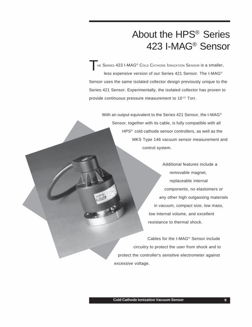
HE SERIES 423 I-MAG® COLD CATHODE IONIZATION SENSOR is a smaller,
less expensive version of our Series 421 Sensor. The I-MAG®
Sensor uses the same isolated collector design previously unique to the
Series 421 Sensor. Experimentally, the isolated collector has proven to
provide continuous pressure measurement to 10-11 Torr.
With an output equivalent to the Series 421 Sensor, the I-MAG®
Sensor, together with its cable, is fully compatible with all
HPS® cold cathode sensor controllers, as well as the
MKS Type 146 vacuum sensor measurement and
control system.
Additional features include a
removable magnet,
replaceable internal
components, no elastomers or
any other high outgassing materials
in vacuum, compact size, low mass,
low internal volume, and excellent
resistance to thermal shock.
Cables for the I-MAG® Sensor include
circuitry to protect the user from shock and to
protect the controller's sensitive electrometer against
excessive voltage.
T
About the HPS® Series423 I-MAG® Sensor

1010 Cold Cathode Ionization Vacuum Sensor
Installing and Using the Series423 I-MAG® Sensor
Locating and Orienting the Sensor
Locate the I-MAG® Sensor where it can measure process chamber ormanifold pressure. Install it away from pumps, other vibration sources, andgas sources to give the most representative values. The magnetic field ofthe Sensor should also be kept away from ion or electron beam sources.
Locate and orient the I-MAG® Sensor where contamination is least likely. Ifit is installed directly above a diffusion pump, for example, oil vapor couldcontaminate the cathode, anode, or other vacuum exposed components,causing the calibration to shift.
The I-MAG® Sensor can be installed with the body set in any direction.Operating position does not affect accuracy. Installing it with the vacuumport facing down is optimal as this helps prevent contaminants falling into it.
Operation at pressures above 10-3 Torr for extended periods illincrease the likelihood of contamination.
Connecting the Sensor
Mount the Sensor to a grounded vacuum system.
If the I-MAG® Sensor has a CF flange, remove the magnet first to allowclearance for bolt installation. When replacing the magnet, note that it iskeyed to the sensor body to protect the feed through pins from damage. Thepins should be straight and centered.
Use an all-metal clamp to mount a KF 25 or KF 40 flanged sensor body.
Connect the cable to the Sensor and to your controller before turning onyour system. Tighten the thumb screw on top of the cable to make sure it issecurely in place and for strain relief.
Starting the Sensor
The I-MAG® Sensor starts quickly in the rough to medium vacuum ranges. Inthe UHV pressure range, starting may be delayed by several minutes. Use aHPS® IgniTorr™ Cold Cathode Starting Device to help significantly reducestarting time (see Accessories, p. 16).

11Cold Cathode Ionization Vacuum Sensor
Operating the Sensor
Operation at pressures above 10-3 Torr for extended periods willincrease the likelihood of contamination.
High voltage should be disabled at pressures above 10-2 Torr toprevent sputtering.
Preparing for Bakeout
Loosen the thumb screw on top of the cable and remove it. Loosen the twoflathead screws located on top of the Sensor, and then remove the magnet.The remainder of the Sensor is ready to be baked out to 500°C if using aCF flange or to 150°C if using a KF flange.

1212 Cold Cathode Ionization Vacuum Sensor
For this chapter, please refer to the figure shown on page 15.
Contamination of the Sensor
If pressure readings appear to be erratic, the Sensor tube may becontaminated. Inspect it visually. If contamination is visible, you shouldreplace the internal components with an Internal Rebuild Kit (seeAccessories, p.16).
Depending on the degree of contamination and application of the Sensor,the internal parts may be cleaned — either ultrasonically, with mildabrasives, or chemically.
Disassembly
Tools required: clean tweezers; clean, smooth-jaw, needle-nose pliers
1 Loosen the thumb screw on top of the sensor cable and thenremove it. Loosen the two flat head screws . Remove themagnet .
2 Using the smooth-jaw, needle-nose pliers, firmly grab thecompression spring at the tip closest to the flange.
3 Pull on the compression spring while rotating it to free it from theformed groove of the sensor body . Continue to pull until thecompression spring is completely free.
4 Carefully remove the remaining components from the sensor body.
Do not bend the anode or the leaf spring on the ion currentfeed through pin when assembling or disassembling theSensor as they are very fragile and could break.
Maintaining the Series 423IMAG® Sensor
1
7
8 913
1415

13Cold Cathode Ionization Vacuum Sensor
Cleaning
If ultrasonic cleaning, use high quality detergents compatible withaluminum, such as ALCONOX®.
Scrubbing with mild abrasives can remove most contamination.Scotch-Brite™ or a fine emery cloth may be effective. Rinse with alcohol.
Clean aluminum and ceramic parts chemically in a wash, such as a 5 to20% sodium hydroxide solution (not for semiconductor processing), at roomtemperature (20°C) for one minute. Follow with a preliminary rinse ofdeionized water. Remove smut (the black residue left on aluminum partsdue to this process) in a 50 to 70% nitric acid dip for about 5 minutes.
Chemical cleaning should not be used to clean the anode; mildabrasives or ultrasonic cleaning are acceptable.
Do not damage the leaf spring while cleaning the Sensor.
Each of the above cleaning methods should be followed with multiple rinsesof deionized water.
Dry all internal components and the sensor body in a clean oven. Thetwo ceramic spacers, and , are slightly porous and will require longerdrying time in the oven to drive off the absorbed water.
Assembly
Wear gloves and assemble with clean tools.
1 Check the anode . It should be straight and centered with thesensor body for proper operation.
2 Roll the sensor body on a flat surface and look for any radialrun out motion.
3 Install the ground shield using tweezers. Make sure that at thegroove of its larger diameter, the ground shield interlocks with thelocating collar .
4 Slide the small ceramic spacer over the small end of theground shield . Check that the leaf spring will contact thebase of the cathode as shown to the right. If not, remove thesmall ceramic spacer and the ground shield. Gently bend the leafspring towards the anode , and then replace the ground shieldand ceramic spacer.
2 5
6
11
4
7
87
56 9
8

1414 Cold Cathode Ionization Vacuum Sensor
5 Slide the cathode , the grid washer , and the large ceramicspacer into place. The grid washer has a concave shape. Referto the figure to see its installation orientation.
6 Insert the small end of the compression spring into the sensorbody . Using your thumbs, push the larger end of the spring intothe sensor body until it is contained within the tube's insidediameter. Using the smooth-jaw, needle-nose pliers, work thecompression spring down into the sensor body until it is fully seatedin the formed groove.
7 Inspect the ground shield and the grid washer to verify theyare centered with respect to the anode . If adjustment is needed,gently reposition the grid washer/cathode assembly, taking care notto scratch the grid washer.
We suggest you measure the resistance between the ion currentfeed through pin and the grid washer to verify that the leafspring is in contact with the cathode . The measurementshould indicate a short circuit between them. There should bean open circuit between the ion current feed through pin andboth the high voltage feed through pin and sensor body .
The I-MAG® Sensor is ready for installation. If it is not immediatelyinstalled, cover the flange with clean, vacuum grade aluminum foil andcap it with a flange protector.
32
1
36
7
8
9
10
13
4
3
137
4
Leaf spring incontact with
cathode

15Cold Cathode Ionization Vacuum Sensor
2
1
3
5
6
7
8
9
10
11
12
13
14
15
4

1616 Cold Cathode Ionization Vacuum Sensor
Accessories / Spare Parts
Part #
IgniTorr™ Cold Cathode Starting Device
120V 100006850220V 100007090
I-MAG® Cold Cathode Cable
2 ft 10000250510 ft 10000787325 ft 10000787450 ft 100002395Custom, to 500 ft 100008759
Internal Rebuild Kit 100002353
Cathode, Grid Washer, Ground Shield,Ceramic Spacers – 1 Sm and 1 Lrg, Spring
Please call HPS® Customer Service Department at 1-303-449-9861 or 1-800-345-1967 to order any of these parts or to receive catalogs for otherHPS® products.

17Cold Cathode Ionization Vacuum Sensor
Extent of the Warranty MKS Instruments, Inc., warrants HPS® Products Series 423 I-MAG® Sensor and its accessories to be freefrom defects in materials and workmanship for one (1) year from the date of shipment by HPS® orauthorized representative to the original purchaser (PURCHASER). Any product or parts of the productrepaired or replaced by HPS® under this warranty are warranted only for the remaining unexpired part of itsone (1) year original warranty period. After expiration of the applicable warranty period, the PURCHASERshall be charged HPS®’ current prices for parts and labor, plus any transportation for any repairs orreplacement.ALL EXPRESS AND IMPLIED WARRANTIES, INCLUDING THE IMPLIED WARRANTIES OFMERCHANTABILITY AND FITNESS FOR A PARTICULAR PURPOSE, ARE LIMITED TO THE WARRANTYPERIOD. NO WARRANTIES, EXPRESS OR IMPLIED, WILL APPLY AFTER THIS PERIOD.
Warranty ServiceThe obligations of HPS® under this warranty shall be at its option: (1) to repair, replace, or adjust theproduct so that it meets applicable product specifications published by HPS® or (2) to refund thepurchase price.
What Is Not CoveredThe product is subject to above terms only if located in the country of the seller from whom the product waspurchased. The above warranties do not apply to:I. Damages or malfunctions due to failure to provide reasonable and necessary maintenance inaccordance with HPS® operating instructions.II. Damages or malfunctions due to chemical or electrolytic influences or use of the product in workingenvironments outside the specification.III. Fuses and all expendable items which by their nature or limited lifetime may not function for a year. Ifsuch items fail to give reasonable service for a reasonable period of time within the warranty period of theproduct; they will, at the option of HPS®, be repaired or replaced.IV. Defects or damages caused by modifications and repairs effected by the original PURCHASER or thirdparties not authorized in the manual.
Condition of Returned ProductsHPS® will not accept for repair, replacement, or credit any product which is asserted to be defective by thePURCHASER, or any product for which paid or unpaid service is desired, if the product is contaminatedwith potentially corrosive, reactive, harmful, or radioactive materials, gases, or chemicals.When products are used with toxic chemicals, or in an atmosphere that is dangerous to the health ofhumans, or is environmentally unsafe, it is the responsibility of the PURCHASER to have the productcleaned by an independent agency skilled and approved in the handling and cleaning of contaminatedmaterials before the product will be accepted by HPS® for repair and/or replacement.In the course of implementing this policy, HPS® Customer Service Personnel may inquire of thePURCHASER whether the product has been contaminated with or exposed to potentially corrosive,reactive, harmful, or radioactive materials, gases, or chemicals when the PURCHASER requests a returnauthorization. Notwithstanding such inquiries, it is the responsibility of the PURCHASER to ensure that noproducts are returned to HPS® which have been contaminated in the aforementioned manner.
Other Rights and RemediesI. These remedies are exclusive. HPS SHALL NOT BE LIABLE FOR CONSEQUENTIAL DAMAGES, FORANTICIPATED OR LOST PROFITS, INCIDENTAL DAMAGES OR LOSS OF TIME, OR OTHER LOSSESINCURRED BY THE PURCHASER OR BY ANY THIRD PARTY IN CONNECTION WITH THE PRODUCTCOVERED BY THIS WARRANTY, OR OTHERWISE. Some states do not allow exclusion or limitation ofincidental or consequential damage or do not allow the limitation on how long an implied warranty lasts. Ifsuch laws apply, the limitations or exclusions expressed herein may not apply to PURCHASER.II. Unless otherwise explicitly agreed in writing, it is understood that these are the only written warrantiesgiven by HPS®. Any statements made by any persons, including representatives of HPS®, which areinconsistent or in conflict with the terms of the warranty shall not be binding on HPS unless reduced towriting and approved by an authorized officer of HPS®.III. This warranty gives PURCHASER specific legal rights, and PURCHASER may also have other rightswhich vary from state to state.IV. For HPS® products sold outside of the U.S., contact your MKS representative for warranty informationand service.
Warranty PerformanceTo obtain warranty satisfaction, contact the following: MKS Instruments, HPS® products Inc., 5330 SterlingDrive, Boulder, CO 80301, USA, at phone number (303) 449-9861.
Product Warranty

1818 Cold Cathode Ionization Vacuum Sensor
NOTES