HPS 16 English
9
Hydropower Plant Simulator HPS-16 Page 1 1. General description of the device HPS-16 1.1 Overview Hydropower Plant Simulator HPS-16 is an integrated system for training Hydropower Plant Operating Personel. With a modular design, so the device can meet the requirements for teaching at many different levels, from the students to the operating engineers. HPS-16 is a harmonious combination of simulation solutions to bring the closest knowledge to the students about the system operating in practice. Besides the flagship device, HPS-16 also incorporates a virtual appliance component thereby allowing teachers can create many types of incidents that are not restricted by the impact on device longevity. A very advanced capabilities of the HPS-16 is the creation of incidents in operation and monitor the activities of students by computer. Teachers can set the operating parameters as you wish, or create abnormal operating conditions in factories so that exercise judgment and troubleshooting of the students. With the integrated SCADA and ability to share databases, HPS-16 may act as a Web Training Base suited for learning via computer networks. Figure 1.1 HPS-16 system overall HPS-16 is designed as an open system and towards the user. Depending on the actual requirements that users can upgrade the system. 1.2 System Structure - Power System of HPS-16 consists of two units, each with a capacity of 8 MW connected to two step-up transformers 6/35 kV (Figure 1.2). The Power generator uses static excitation with full features of the actual generator. The plant is designed to operate independently or synchronous to grid. Two power
description
Hydro Power Plant Simulator System HPS-16
Transcript of HPS 16 English

Hydropower Plant Simulator HPS-16
Page 1
1. General description of the device HPS-16
1.1 Overview
Hydropower Plant Simulator HPS-16 is an integrated system for training
Hydropower Plant Operating Personel. With a modular design, so the device
can meet the requirements for teaching at many different levels, from the
students to the operating engineers.
HPS-16 is a harmonious combination of simulation solutions to bring the
closest knowledge to the students about the system operating in practice.
Besides the flagship device, HPS-16 also incorporates a virtual appliance
component thereby allowing teachers can create many types of incidents that
are not restricted by the impact on device longevity.
A very advanced capabilities of the HPS-16 is the creation of incidents in
operation and monitor the activities of students by computer. Teachers can set
the operating parameters as you wish, or create abnormal operating conditions
in factories so that exercise judgment and troubleshooting of the students.
With the integrated SCADA and ability to share databases, HPS-16 may act
as a Web Training Base suited for learning via computer networks.
Figure 1.1 HPS-16 system overall
HPS-16 is designed as an open system and towards the user. Depending on
the actual requirements that users can upgrade the system.
1.2 System Structure
- Power System of HPS-16 consists of two units, each with a capacity of 8
MW connected to two step-up transformers 6/35 kV (Figure 1.2). The Power
generator uses static excitation with full features of the actual generator. The
plant is designed to operate independently or synchronous to grid. Two power
Hydropower Plant Simulator HPS-16
Page 2
transformers 8 MW connected to the grid in the diagram a busbar system has
segmented by CB.
Cooling system and oil pressure: Both systems are using the software
simulator running on the server, logic diagrams and pictures of operation of
the system is illustrated intuitive, interactive two-way by touchscreen (Figure
1.4).
Relay protection system: Sufficient protection of hydroelectric generators
include: generator differential relay Protection, Over speed relay protection,
overcurrent relay protection, overvoltage ...
Control system: The control system of HPS-16 including 1 database server,
06 machine operators and industrial communication networks.
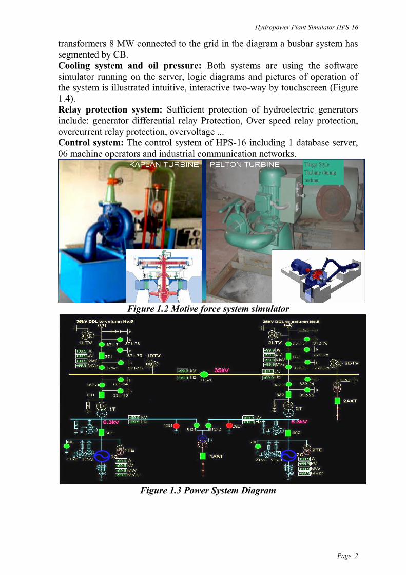
Figure 1.2 Motive force system simulator
Figure 1.3 Power System Diagram

Hydropower Plant Simulator HPS-16
Page 3
Figure 1.4 Virtual device
1.3 Generators, Turbine and protection systems for generators:
- Turbine: Include two kinds of turbine are Kaplan and Turgo
corresponding to two different pipe systems, each turbine has 1 kW power.
Figure 1.5 and Turgo Kaplan Turbine
- Generators: Two 3-phases static excitation generator with output voltage
220/127 V.
- Control system:
The mechanical turbine governor (optional).
The electricity rate: Use of PID controllers for excitation and steady
pace.
Generator Measurment
Generator Speed
Flow and water pressure.
Temperature of generators at many locations.
Corner open vanes.
- Generator Protection:
Over speed Protection.
Over current protection.
Over voltage protection.
Earth fault protection

Hydropower Plant Simulator HPS-16
Page 4
Differential Protection.
Reverse power protection.
Overload protection and Negative sequence overload protection.
- Auto synchronizing device:
Including Manual and Auto synchronizing supervisor.
- Hydropower plant simulation system HPS-16 is designed based on
hydropower plant Dray Hlinh 2. The control circuit and power circuit are
isolated with the grid by the isolation transformer, that ensure safety
principles when conducting practice on the system.
- With the ability to re-configure, the system allows easy upgrade and
expand. Teachers can study to expand the upgrade by themselves.
- Step-up Substation :
Two 16MW transformers in parallel connection via a busbar system with
segmented by CB. Voltage can be adjusted in the range of 5%.
- The control system for transformers:
Control pressure head distribution.
The forced cooling fan system
- The relays protection of substations:
Overload protection of transformers.
Transformer Differential
Protection.
Buchholz relay
External short circuit protection.
Earth Fault Protection.
Busbar Differential Protection.
Figure 1.6 Control and synchronizing
1.4 Auxiliary power and battery:
Auxiliary power was supplied by auxiliary transformer 35/6 kV. In case the
plant stopped completely, Auxiliary power was supplied from the local grid or
from the 100 kW backup diesel generator. Auxiliary power system includes
the following main parts:
Battery charger system.
Monitoring and Automatic Transfer Switch system (ATS).
DC insulation supervisor system device.
Battery charge.
Emergency lighting system.
1.5 The alarm system and processing monitor:
- Alarm system:
Hydropower Plant has Alarm systems, Central alarm lights, Alarm at control
cabinet and on the operating software.
- Processing monitor:

Hydropower Plant Simulator HPS-16
Page 5
When the teacher allows for automatic processing monitor, this feature will
be activated and then student’s action are monitored. If you are using the
software integrates with supporting online training, the teaching on this
system can conduct remote, not classroom teachers need to be present that
could create a problem and found command system regulation.
Figure 1.7 System control and supevisor diagram
1.6 Training Ability
Training workers for operating hydroelectric plant.
Training Engineer – chief operating shift of Hydropower plant.
Training Operating Engineers of the control system in hydropower
plants.
Training level rising and qualification operation for hydropower plants.
1.7 HPS-16 price
Depend on the option request, for basic configuration including
hardware and software is about 50.000 USD.
We need 6 months for new system installation.
2. Operating guide:
2.1 Operating sequence at the control cabinet
- Generator operation:
Step 1: Check the conditions required to launch include: water
generator, cooling system, oil pressure systems, lubrication systems,
warning signals and alarm signals are in the ready state.

Hydropower Plant Simulator HPS-16
Page 6
Step 2: Turn the control key from STOP position to OPERATION
position, if there is a problem at this step , the system send a signal not
allowed booting.
Step 3: Release brakes "Break" for starting generator in no-load mode,
generator speed will reach 90 % and excitation system will start
working. In this time, the turbine governor system will automatically
adjust speed generator reaches 100% rated speed with reaching the
rated excitation current in no-load mode. Subscribe to the warning
signals and the parameter on the control cabinet.
Step 4: If the synchronized signal has started, changed to the position
prepared synchronizing. Subscribe synchronized lights on the control
panel, synchronized lights sparkling at a slow speed and stopped at the
0 position then close the Generator's Circuit Breaker (CB 601 or CB
602), generators will operate in synchronized modes. Observe the
power, current, voltage parameters and excitation voltage on the control
cabinet. This is the most important step of booting generator. If there is
any abnormal phenomenon occurred must immediately emergency
stop.
Step 5: After 1 minute put into operation in parallel mode, the
controller will adjust the generator transmit at 10% rated level mode, in
this time operating personnel can adjust the load as required by load
curve of Load Dispatch Center.
- Step-up substation operation:
Step-up Substation includes two transformers operated in parallel mode
at the 35 kV.
Notes: Subscribe the parameters of the transformer during operation.
Before generator operation, check the correct connection diagram at the
step up substation. Although there are operation conditions between
Circuit Breakers and Disconnecting Switches but not allowed to change
Disconnecting Switches position in any situation when Circuit Breakers
are opening.
Subscribe operating temperature and the protection alarm signals of
Step-up substation.
- Auxiliary power system operation:
Auxiliary power system whose role is particularly important in
hydropower plants, when the plant stopped, the power is supplied from
the auxiliary transformer TD1 (35/6 kV) to start the generator and
appliances auxiliary. When the generator has been operating, the
Automatic Transfer Switch (ATS) will take power from 6 kV bus bar.
- Some notes during operation:
During preparations need to check source voltage, the status of the
turbines, and safety support parts. During turbine acceleration if the
speed increased instability or abnormal noise from the turbines, the
machines must be stop immediately , check the turbine and generator to

Hydropower Plant Simulator HPS-16
Page 7
find exact abnormal phenomenon. Check the status and temperature of
the bearing.
Auxiliary voltage of the whole system are supplied from the 24V
battery in the auxiliary cabinet, should preserve battery system
according to user guide to avoid damaging the battery and the device
with 24V input.
2.2 Control software SD-200 operation
Similar to manual operation, the control operations at the hydropower
plant can be remote controlled with software controller SD-200. The start,
stop and adjust the operating parameters are operated on the computer. The
data requirements and controls are accessible through the server computer
with HPS-SRV software, which is programmed based on DAQFactory
The main console
1G: Generator Controller 1
2G: Generator Controller 2
PUB: System operational diagram

Hydropower Plant Simulator HPS-16
Page 8
- Generator 1&2 Control Interface
Hydropower Plant operation completely by software similar to manual
operation at the control cabinets, requires an Operator password for
controlling, the password is provided by teachers according operating level.

Hydropower Plant Simulator HPS-16
Page 9
3. Preservation
- Every 6 months, check exposed connection point of power circuit, check
the color to find the yellowed phenomenon of connection point by
overheating or not.
- Once a year check the condition of the grounding system and the pump
pressure.
- The system operates based on combination of hardware and software so
that software maintenance, scan virus are necessary, absolutely not use
USB copy data directly from the computer operator.
- To ensure that operating parameters are exactly, the environment
temperature in where the appliance are placed does not exceed 300C.
4. Requirements before installation
Dimensions (LxWxH) 3.2x0.8x2.2 m
Net weight 2000 kg excluding turbine
Operating voltage 220/380
Computer: IBM® System® x3250M3 1 server (4252C2A), 100Mb
LAN, WiFi, SMS Modem and 06 PC
Maximum power system 5kW, and 2kW when synchronous to grid
Operating temperature allows 400C