HPE Aruba IAP v6.5 Bootcamp - Ministry of Public...
186
1 Aruba Instant Access Point bootcamp - v6.5 Henderson Iturralde | MCA SE henderson.iturralde @ hpe.com 2018.04.26
Transcript of HPE Aruba IAP v6.5 Bootcamp - Ministry of Public...

1
ArubaInstant Access Point bootcamp - v6.5
Henderson Iturralde | MCA SE
henderson.iturralde @ hpe.com 2018.04.26

2
Objectives:
• To reach a general knowledge for the HPE Aruba IAP 100, 200 and 300 Series.
• To use the IAP’s GUI, Local Instant Manager.
• To execute the installation and startup.
• To know and understand the basic and middle ArubaOS features.

3
Audience
• Networking Services Engineers with:
▪ Knowledge of HPN Aruba products or other networking brands.
▪ Previous experience in setting up networking devices.
▪ Knowledge of networking technologies (LAN & wLAN).
• Advanced pre-sales with previous experience in the field:
▪ It applies the previous requirements.
• It is not intended to :
▪ Sales people or administrative roles.
▪ Without knowledge of networking.
This bootcamp is intended for:

4
Bootcamp prerequisites
• A personal computer.
• Applications for console connection: serial and telnet (ex: Putty, TeraTerm), web
browser (Chrome, FireFox).
• Console cable (RJ45).
• UTP patch cords (at least two, with RJ45 connectors in good conditions).
• A clip (... yes, a clip).
Attendees should bring the following tools:

5
During the bootcamp
• Answer phone calls.
• Chat.
• Review e-mails.
Attendees should not:

6
General agenda
• Information and documentation resources.
• The IAP, Instant Access Point.
• Startup and Users.
• SSIDs and VLANs.
• Profiles and roles.
• Captive Portal.
• Authentication.
• Security.
• ARM, Adaptive Radio Management.
• Management and Monitoring.
• Mesh.

7
Introductions
• Name
• Title
• Employer
• Current job responsibilities
• Networking experience
• Course Objectives
• Schedule:
▪ 09h00 to 14h00
• One participant per IAP

8
Information and documentation resources

9
HPE Aruba tech info
• HPE Aruba on the Internet
▪ www.hpe.com/networking
▪ www.arubanetworks.com
▪ www.arubapedia.arubanetworks.com
• Aruba - Validated Reference Design Guides
(VRD)
▪ www.arubanetworks.com/technology/reference
-design-guides/
• Aruba Support
▪ www.arubanetworks.com/support-
services/support-program/contactsupport/
▪ support.arubanetworks.com

10
AirHeads Community
http://airheads.arubanetworks.com
Create a conversation or
make a question Query the database
Foreign languages

11
IAP Manuals
IAP Bootcamp reference literature
support.arubanetworks.com
> Documentation
> Software User & Reference Guides
> Aruba Instant
> Current Release
> Instant 6.5.3.0

12
WW product compliance status
geocompliance.arubanetworks.com
QueryFor example “Ecuador”

13
Recommended wLAN tech books
• CWTS Certified Wireless Technology Specialist
• CWNA Certified Wireless Network Administrator
• CWSP Certified Wireless Security Professional
• CWDP Certified Wireless Design Professional
• CWAP Certified Wireless Analysis Professional
• CWNE Certified Wireless Network Expert
www.cwnp.com

14
Additional resources
• IEEE www.ieee.org
▪ Define standards.
• Wi-Fi Alliance www.wi-fi.org
▪ Certify interoperability between different brands.
• CWNP www.cwnp.com
▪ Documentation and technical certification.

15
Labs

16
Topology

17
Groups info
Group Switch ports VLAN IP add Def Gat PC AP VCSystem Name
AP Name
1 1 and 2 101192.168.101.0
/ 24.1 .2 .3 .10 Cluster_01 IAP_01a
3 3 and 4 103192.168.103.0
/ 24.1 .2 .3 .10 Cluster_03 IAP_03a
5 5 and 6 105192.168.105.0
/ 24.1 .2 .3 .10 Cluster_05 IAP_05a
7 7 and 8 107192.168.107.0
/ 24.1 .2 .3 .10 Cluster_07 IAP_07a
9 9 and 10 109192.168.109.0
/ 24.1 .2 .3 .10 Cluster_09 IAP_09a
11 11 and 12 111192.168.111.0
/ 24.1 .2 .3 .10 Cluster_11 IAP_11a
13 13 and 14 113192.168.113.0
/ 24.1 .2 .3 .10 Cluster_13 IAP_13a
15 15 and 16 115192.168.115.0
/ 24.1 .2 .3 .10 Cluster_15 IAP_15a
17 17 and 18 117192.168.117.0
/ 24.1 .2 .3 .10 Cluster_17 IAP_17a
19 19 and 20 119192.168.119.0
/ 24.1 .2 .3 .10 Cluster_19 IAP_19a
21 21 and 22 121192.168.121.0
/ 24.1 .2 .3 .10 Cluster_21 IAP_21a
2323 and
MSR900 e0/3123
192.168.99.0/ 24
.1 .2 .3 .10 Cluster_23 IAP_23a

18
IAP, Instant Access Point• Features
• Uses
• Scope
• Summary Portfolio

19
IAP operation planes
Centralized Management
Configuration, monitoring,
firmware upgrades by elected
virtual controller or network
managementDistributed Control Plane
Authentication, access control,
guest access on APs
Distributed Data Plane
Firewall, Application Layer
Gateway (ALG) bridging on APs
Wireless Controller Functionality Virtualized
Eliminate cost & manpower needed to install & maintain an additional appliance

20
Summary operation
The IAP integrates AP and Mobility Controller services
• Configure the first IAP. This will act simultaneously as AP and
Controller for the local IAP group.
– The IAP group is called cluster.
• Additional IAPs will work as Controlled APs and Backup
Controllers (N + 1).
• For management, the AOS includes Local Instant Manager.
• Changing the configuration, the IAP can work as controlled AP
(CAP or RAP) in a Controller based solution.
Instant APsScalability
− Max 128 IAPs per cluster.
− Max 2K concurrent wireless clients per cluster.
− Up to 16 SSIDs per cluster.
− All IAPs must be in the same management VLAN.
− All IAPs must have the same AOS version.

21
Master Election – 4 States
Potential Master
Timeout
InitialBoot
Master
Send beacons out/sec
Timeout

22
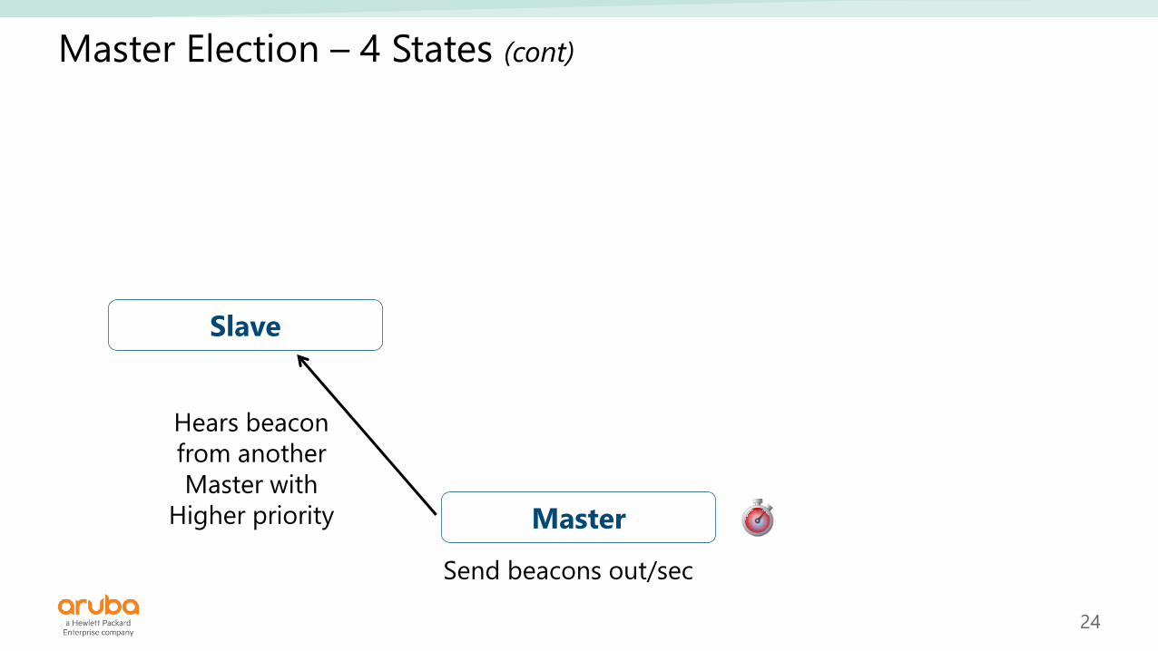
Master Election – 4 States (cont)
Hears beacon
InitialBoot
Master
Send beacons out/sec
Slave
Beacons

23
Master Election – 4 States (cont)
Slave Potential Master
Hears beacon from AP
with Higher Rule
Timeout
Master
Send beacons out/sec
Timeout
24
Master Election – 4 States (cont)
Slave
Hears beacon
from another
Master with
Higher priority Master
Send beacons out/sec

25
Master Election – 4 States (cont)
Slave Potential Master
TimeoutHears beacon
Hears beacon from AP
with Higher Rule
Timeout
Hears beacon
from another
Master with
Higher priority
InitialBoot
Master
Send beacons out/sec
Timeout
Beacons

26
Indoor APs / IAPs
220 Series (AP/IAP-22x)Dual radio, 802.11ac 3x3:3SS, 2xGE, USB
High performance 11ac W1 non-blocking
200 Series (AP/IAP-20x)Dual radio, 11ac 2x2:2SS, 1xGE
Baseline 2x2 11ac platform
210 Series (AP/IAP-21x)Dual radio, 802.11ac 3x3:3SS, 1xGE, USB
Medium line 3x3 11ac platform
802.11ac Wave 1
330 Series (AP/IAP-33x)802.11ac 4x4:4SS, MU-MIMO, VHT160
1x 1GE + 1x 2.5GE, USB, BLE
Flagship 11ac W2 non-blocking
320 Series (AP/IAP-32x)Dual radio, 802.11ac 4X4:4SS MU-MIMO
2xGE, USB, BLE
High performance 11ac W2 platform
310 Series (AP/IAP-31x)802.11ac 4x4:4SS, MU-MIMO, VHT160
1x GE, USB, BLE, 802.3af POE
Medium line 4x4 11ac W2 platform
802.11ac Wave 2802.11n
103 Series (AP/IAP-103)Dual radio, 11n 2x2:2SS, 1xGE
Low-cost 2x2 11n platform
300 Series (AP/IAP-30x)802.11ac 3x3:3SS, MU-MIMO, VHT160
1x GE, BLE, 802.3af POE
Baseline 3x3 11ac W2 platform

27
Remote, Hospitality & Branch
RAP-108/109Dual radio, 11abgn 2x2:2SS
1xGE + 1xFE, USB
Mid market RAP 11n
RAP-155(P)Dual radio
11abgn 3x3:3SS (5GHz) & 2x2:2SS (2.4GHz)
1xGE +4xGE, USB, 2xPSE
Flagship RAP 11n
AP-103HDual radio, 802.11n 2x2:2SS
1xGE + 2xFE + PT
Low cost moderate density 11n Hospitality AP 11
AP/IAP-205HDual radio, 802.11ac 2x2:2SS
1xGE + 3xGE + PT, USB, 1xPSE
High performance 11ac Hospitality & RAP

28
Remote, Hospitality & Branch (cont)
• Dual band
▪ 5G radio 11ac-80MHz, 2x2
▪ 2G radio 11n-40MHz, 2x2
• Ports
▪ One Uplink Gig Ethernet port (E0)
▪ Three Downlink Gig Ethernet ports (E1-E3).
▪ E3 with PSE.
▪ One Pass-through interface (E0/PT)
▪ One Console port (Aruba 4 pins connector)
▪ USB 2.0 support

29
Outdoor APs / IAPs
AP/AIP 275Integrated Omnis
Dual Radio
11ac 3x3:3SS
AP/IAP 274Connectorized
Dual Radio
11ac 3x3:3SS
AP/IAP 277Integrated
Directional
Dual Radio
11ac 3x3:3SS
AP-228 Hardened AP6 x RPSMA connectors
Dual Radio
11ac 3x3:3SS
AP/AIP 365Integrated Omnis
AP/AIP 367Integrated Directional
Dual Radio
11ac Wave2 2x2:3SS

30
802.11ac summary portfolio
Model Location Density Vertical
300
SeriesIndoor
Moderate
(50/75+ active)
K-12, Retail
Hospitality
303H IndoorModerate
(50/75+ active)
Hospitality, Branch Offices,
Remote Workers
310
SeriesIndoor
High
(75/115+ active)
Carpeted space
across verticals
320
SeriesIndoor
High
(75/115+ active)
Higher Ed,
Enterprises
330
SeriesIndoor
Very High
(100/150+ active)
Higher Ed,
Enterprises
360
SeriesOutdoor
Moderate
(50/75+ active)
Outdoor,
Warehouses
WAVE 2
WAVE 1
Model Location Density Vertical
200
Series,
205H
Indoor Moderate
(50/75+ active)
K-12, Retail
Hospitality
203H IndoorLow
(15/25+ active)
Hospitality, Branch Offices,
Remote Workers
203R IndoorModerate
(50/75+ active)
Branch Offices,
Remote Workers
207
SeriesIndoor
Moderate
(50/75+ active)
K-12, Retail
Hospitality
210
SeriesIndoor
Moderate
(50/75+ active)
K12, Hospitality, Retail,
Carpeted space
220
SeriesIndoor
High
(75/115+ active)
Higher Ed,
Enterprises
228Indoor
Rugged
High
(75/115+ active)
Indoor Rugged,
Warehouses
270
SeriesOutdoor
High
(75/115+ active)
Outdoor,
Warehouses

31
IAP 3x0 Series
AP/IAP 2x0 AP/IAP 3x0
4x4 / 4SS
MU-MIMO (3SS)
BLE

32
802.11ac Wave 2
Drivers for 802.11ac Wave2
Increased devices per user Real time video Skype for business
Cloud services Video Streaming Internet of Things

33
802.11ac Wave 2 (cont)
Unique benefits of 802.11ac Wave2
Higher utilization of the network
MU-MIMO entregael rendimiento del
switch a la movilidad
MU-MIMO brings switch performance
to mobility
Supports ultra-high bandwidth
applications
Wider channels

34
802.11ac Wave 2 (cont)
Comparisons
Voice over Wi-Fi
All wireless office
The Digital Workplace

35
802.11ac Wave 2 (cont)
Best practices
• With Wave 2, the wireless network becomes the
primary network.
• Follow these best practices for optimal results.
Best Practices
Deploy with 80MHz channels until
government opens more spectrum to
allow 160MHz channels
Plan AP coverage for 5GHz range
802.11ac Wave1 and Wave2 APs can be
mixed, with Wave2 in highest density areas
Leverage either dual or multi-GigE uplinks for W2 APs to allow future speed boosts when 160MHz is deployable

36
What is MU-MIMO?
• Enables simultaneous transmissions of data from AP to multiple clients
(downstream only), optimizing the use of AP resources
Multi User - Multiple Input Multiple Output
1SS
SU-MIMO:
2 “wasted” streams
1SS
1SS
1SS
MU-MIMO (Wave 2)
uses all streams

37
Aruba Instant Features
• Recommended for:
▪ Distributed enterprises.
▪ Autonomous sites.
▪ Small to Mid size organizations.
• Design:
▪ Management based on a virtual controller
(Virtual Controller, VC).
▪ IAPs automatically associate to the cluster
when they are installed on VC’s VLAN.
▪ Plug and Play.
▪ Each IAP can work as a controller for VC
redundancy.
▪ Easy conversion from IAP to a controlled mode
(CAP or RAP).
▪ The IAP includes full OS features (no
licensing).
▪ All IAP (Indoor and Outdoor) includes lifetime
warranty.

38
Aruba Instant Features (cont)
• Authentication:
▪ 802.1X, WPA, WPA2
▪ MAC
▪ Captive Portal
▪ Infrastructure:
• Built in Database
• Dynamic Radius Proxy
• Radio Features:
▪ Authentication Infrastructure
▪ Adaptive Radio Management
(ARM)
▪ Client match
▪ Spectrum Analysis
▪ Voice aware scan
• Encryption:
▪ AES, TKIP, WEP
• Firewall:
▪ Statefull Firewall
▪ User based Roles
▪ WLAN based rules
▪ Extended Actions
▪ Voice ACLs
▪ AppRF (Layer 7 analysis)
• Service:
▪ Cloud based content filtering
(OpenDNS)
▪ OS Fingerprinting
• Management:
▪ Built-in Local Instant Manager
▪ Airwave (on premise)
▪ Aruba Central (cloud service)
• IDS / PDS
▪ Rogue AP Detection and
Classification

39
Management options
IAP Cluster
Instant UI
IAP Cluster
Instant UIInternet
Aruba
Central
Mobility
Controller
ClearPass
AD / RADIUS
Enterprise HQ
Aruba
Airwave
WAN
40
Local Instant Manager• Default factory configuration
• Initial configurations

41
In this module
• Return the IAP configuration to factory settings:
▪ Reset button.
▪ Using command line in apboot mode.
• Know the Local Instant Manager GUI interface.
• Configure:
▪ Cluster name.
▪ IAP name.
▪ IP address.
• Basic Statistics.

42
Default Factory configuration
• Press and hold the Reset button.
• Turn-on the IAP (PoE/PoE+ switch, DC adapter).
• Wait 5 seconds, then release the button.
Opt 1 - Reset button
IAP 103 IAP 205HIAP 225
Reset
Button

43
Console port connection
IAP 103 IAP 205HIAP 225
Reset
Button

44
Default Factory configuration.... TEXT DELETED ....
Power: 802.3at POE
Net: eth0
Radio: bcm43460#0, bcm43460#1
Hit <Enter> to stop autoboot: 1
apboot>
apboot> ?
? - alias for 'help'
boot - boot the OS image
clear - clear the OS image or other information
dhcp - invoke DHCP client to obtain IP/boot params
factory_reset - reset to factory defaults
help - print online help
mfginfo - show manufacturing info
osinfo - show the OS image version(s)
ping - send ICMP ECHO_REQUEST to network host
printenv - print environment variables
purgeenv - restore default environment variables
reset - Perform RESET of the CPU
saveenv - save environment variables to persistent storage
setenv - set environment variables
tftpboot - boot image via network using TFTP protocol
upgrade - upgrade the APBoot or OS image
version - display version
apboot>
* Requires console (local) connection
Press <Enter> key before the
timer expires (3 seconds)
Opt 2 - apboot (CLI)*

45
Default Factory configuration (cont)
apboot> factory_reset
Clearing state... Checking OS image and flags
Image is signed; verifying checksum... passed
Preserving image partition 0
Erasing flash sector @ 0x1ff80000.... done
Erased 1 sectors
.... TEXT DELETED ....
done
Purging environment... preserving os_partition (0)
Erasing flash...Writing to flash..................done
done
apboot>
apboot> purgeenv
preserving os_partition (0)
Erasing flash...Writing to flash..................done
apboot>
apboot> saveenv
Saving Environment to Flash...
Erasing flash...Writing to flash..................done
apboot>
apboot>
apboot> reset
Process:
1. Turn on the IAP.
2. The console shows a three seconds
countdown. Press the <Enter> key to
interrupt the normal start-up.
3. The IAP starts the apboot mode.
4. Use the factory_reset and reset
commands.
5. Depending on the previous
deployment, it may require changes
in environment variables, if so, use
purgeenv, setenv, and saveenv
commands.
46
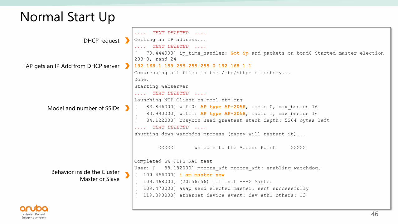
Normal Start Up.... TEXT DELETED ....
Getting an IP address...
.... TEXT DELETED ....
[ 70.444000] ip_time_handler: Got ip and packets on bond0 Started master election
203-0, rand 24
192.168.1.159 255.255.255.0 192.168.1.1
Compressing all files in the /etc/httpd directory...
Done.
Starting Webserver
.... TEXT DELETED ....
Launching NTP Client on pool.ntp.org
[ 83.846000] wifi0: AP type AP-205H, radio 0, max_bssids 16
[ 83.990000] wifi1: AP type AP-205H, radio 1, max_bssids 16
[ 84.122000] busybox used greatest stack depth: 5264 bytes left
.... TEXT DELETED ....
shutting down watchdog process (nanny will restart it)...
<<<<< Welcome to the Access Point >>>>>
Completed SW FIPS KAT test
User: [ 88.182000] mpcore_wdt mpcore_wdt: enabling watchdog.
[ 109.466000] i am master now
[ 109.468000] (20:56:56) !!! Init ---> Master
[ 109.470000] asap_send_elected_master: sent successfully
[ 119.890000] ethernet_device_event: dev eth1 others: 13
DHCP request
Behavior inside the Cluster
Master or Slave
IAP gets an IP Add from DHCP server
Model and number of SSIDs
47
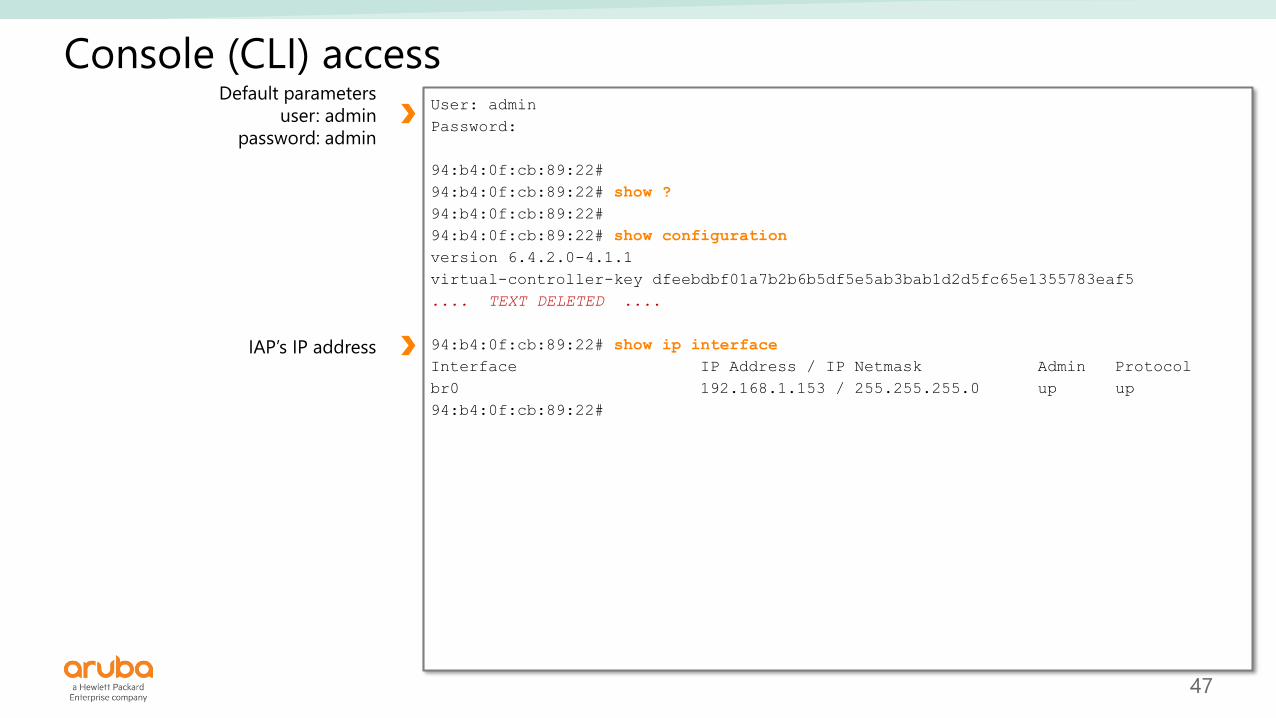
Console (CLI) accessUser: admin
Password:
94:b4:0f:cb:89:22#
94:b4:0f:cb:89:22# show ?
94:b4:0f:cb:89:22#
94:b4:0f:cb:89:22# show configuration
version 6.4.2.0-4.1.1
virtual-controller-key dfeebdbf01a7b2b6b5df5e5ab3bab1d2d5fc65e1355783eaf5
.... TEXT DELETED ....
94:b4:0f:cb:89:22# show ip interface
Interface IP Address / IP Netmask Admin Protocol
br0 192.168.1.153 / 255.255.255.0 up up
94:b4:0f:cb:89:22#
Default parameters
user: admin
password: admin
IAP’s IP address

48
IP Address static configuration
1. Start apboot mode (press <Enter> key before timer expires)
2. Configure environment variables:
Hit <Enter> to stop autoboot: 0
apboot>
apboot> setenv ipaddr 192.0.2.0
apboot> setenv netmask 255.255.255.0
apboot> setenv gatewayip 192.0.2.2
apboot> save
Saving Environment to Flash...
Un-Protected 1 sectors
.done
Erased 1 sectors
Writing
3. Confirm configuration and reset:
apboot> printenv
apboot> reset
In apboot mode

49
IP Address static configuration
ip-address <ip-address> <subnet-mask> <nexthop-ip-address> <dns-ip-address> <domain-name>
Parameters:
<ip-address> Define IP Address
<subnet-mask> Define mask
<nexthop-ip-address> Define Default Gateway
<dns-ip-address> Specify the DNS server
<domain-name> Specify the Domain Name
Reference:
This command statically configure the IAP’s IP address.
Require IAP restart after setup.
Example:
(Instant AP)# ip-address 192.0.2.99 255.255.255.0 192.0.2.3 192.0.2.2 example.com
(Instant AP)# reload
Through CLI

50
Local Initial Setup
• Open a browser window (recommended
Google Chrome or FireFox).
• Use the IAP’s IP address (assigned by the
DHCP server): 192.168.1xx.3.
▪ To know the IP address review the console
logs or the show ip interface command.
▪ Without console access you can use a
network scanner, look for “Aruba” vendor.
• Without console access or network
scanner, you can use a wireless connection
to the SSID:
▪ Instant, or,
▪ SetMeUp-nn: nn: nn (in v6.5.2)
Username: admin
Password: admin

51
Country Code

52
Aruba Central
Demo License
• In this bootcamp, press [Close].
▪ For details review the Aruba Central bootcamp.

53
Local Instant Manager
Views
Banner
Configuration Links
Statistic
Links

54
Language

55
VC: name and IP Address configuration

56
Virtual Controller, VC
• Each cluster has an IAP Master that works as VC.
• If the IAP Master stops working, a Slave takes its place and performs the Master
functions.
▪ The new IAP Master uses the VC’s IP address.
VC
VC
VC

57
AP configuration
IAP Master

58
Lab 01
• Consider:
▪ GG is the group number (01, 03, etc).
• Return configuration to factory
settings.
• Define Region.
• Configure the cluster name:
▪ Cluster_GG
• Configure VC IP Address:
▪ 192.168.1GG.10
• Configure AP name:
▪ AP_GGa
• Review statistics:
▪ Info.
▪ RF Dashboard.
▪ Monitoring, etc.
IAP initial configuration and statistics

59
Startup• Wizards
• SSID
• VLANs
• Zones

60
In this module
• Configure a “Primary usage Employee” SSID:
▪ Name
▪ Type
▪ VLAN assignment
▪ IP Add assignment
▪ 802.11 authentication and encryption
▪ Zones
61
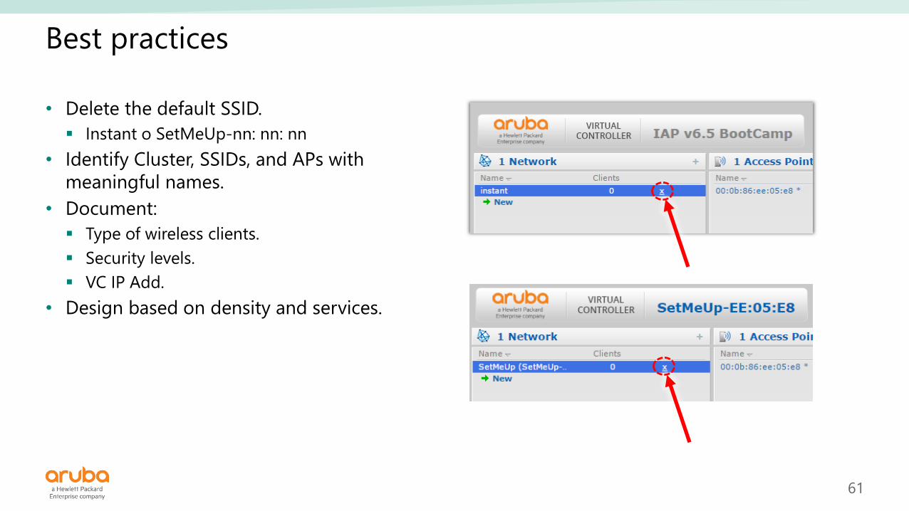
Best practices
• Delete the default SSID.
▪ Instant o SetMeUp-nn: nn: nn
• Identify Cluster, SSIDs, and APs with
meaningful names.
• Document:
▪ Type of wireless clients.
▪ Security levels.
▪ VC IP Add.
• Design based on density and services.

62
WLAN Wizards
SSID
Employee
Voice
Guest
VC Assigned
Default
Custom
Network Assigned
Default
Static
Dynamic
Enterprise
Personal
Open
Captive Portal
Role based
Network Base
Unrestricted

63
WLAN Setting = SSID

64
WLAN Setting - Advanced Options

65
IP Address and VLAN assignment
The VC’s DHCP server
assigns IP Add to the client

66
IP Address and VLAN assignment (cont)
The enterprise DHCP server
assigns IP Add to the client

67
Virtual Controller managed - Default
Opt 1
vLAN 10
NAT & DHCP172.31.98.X
or
10.254.98.X
10.1.10.56

68
Virtual Controller managed - Custom
Opt 2
vLAN 1010.1.10.56
NAT & DHCP

69
Network assigned - Default
Opt 3
vLAN 10
10.1.10.57
10.1.10.110.1.10.49
DHCP

70
SSID Teachers: vLAN 5
SSID Student: vLAN POOL 16,17,18
Network assigned - Static
Opt 4
10.1.10.56vLAN 10
802.1q
10.58.5.78 (vLAN 5)
172.16.16.56 (vLAN 16)
vLAN: 5, 16, 17, 18
DHCP

71
Value= vLAN 16
SSID School
Network assigned - Dynamic
Opt 5
10.1.10.56vLAN 10
802.1q
10.58.16.78 (vLAN 16)
vLAN: 5, 16
DHCP
Radius (ClearPass)

72
Network assigned - Dynamic (cont)
Rules

73
Security: Open

74
Security: Personal

76
Security: 802.1x

77
Recommended Authentication and Encryption Combinations

78
Access (Firewall)

79
The new SSID is configured

80
Zones
• Zones assign an SSID to a specific IAP.
• Constraints to the AP zone
configuration:
▪ An IAP can belong to only one zone
and only one zone can be configured
on an SSID.
▪ If an SSID belongs to a zone, all IAPs in
this zone can broadcast this SSID. If no
IAP belongs to the zone configured on
the SSID, the SSID is not broadcast.
▪ If an SSID does not belong to any zone,
all IAPs can broadcast this SSID.
Cluster
employee
employee
Zone1
guest
AP1
AP2
AP3
employeeguest
guest
guest
guest

81
AP Zone configuration

82
SSID Zone configuration

83
Lab 02
• Consider:
▪ GG is the group number (01, 03, etc)
• Create an “Employee” SSID:
▪ Recommended SSID name: “employeeGG”
• Assign the VLAN:
▪ Virtual Controller Managed
▪ Default
• Security:
▪ WPA2 Personal
▪ pass: labempleyeeGG
• Access:
▪ Unrestricted
• Connect a wireless client to the new
employee SSID
▪ In the client device:
• Review IP Add
• Open a window browser and surf
• Change the VLAN assignment configuration:
▪ Network Assignment
▪ Default
▪ In the client device:
• Review IP Add
• Open a windows browser and surf
SSID for employees

84
Access• Profiles
• Rules
• Roles

85
In this module
• Access Control (FW)
• Content filtering

86
WLAN Wizards
SSID
Employee
Voice
Guest
VC Assigned
Default
Custom
Network Assigned
Default
Static
Dynamic
Enterprise
Personal
Open
Captive Portal
Role based
Network Base
Unrestricted

87
Access Control

88
Access Control
Opt 1 - Unrestricted
No rules
Unrestricted- SSID
No rules
89
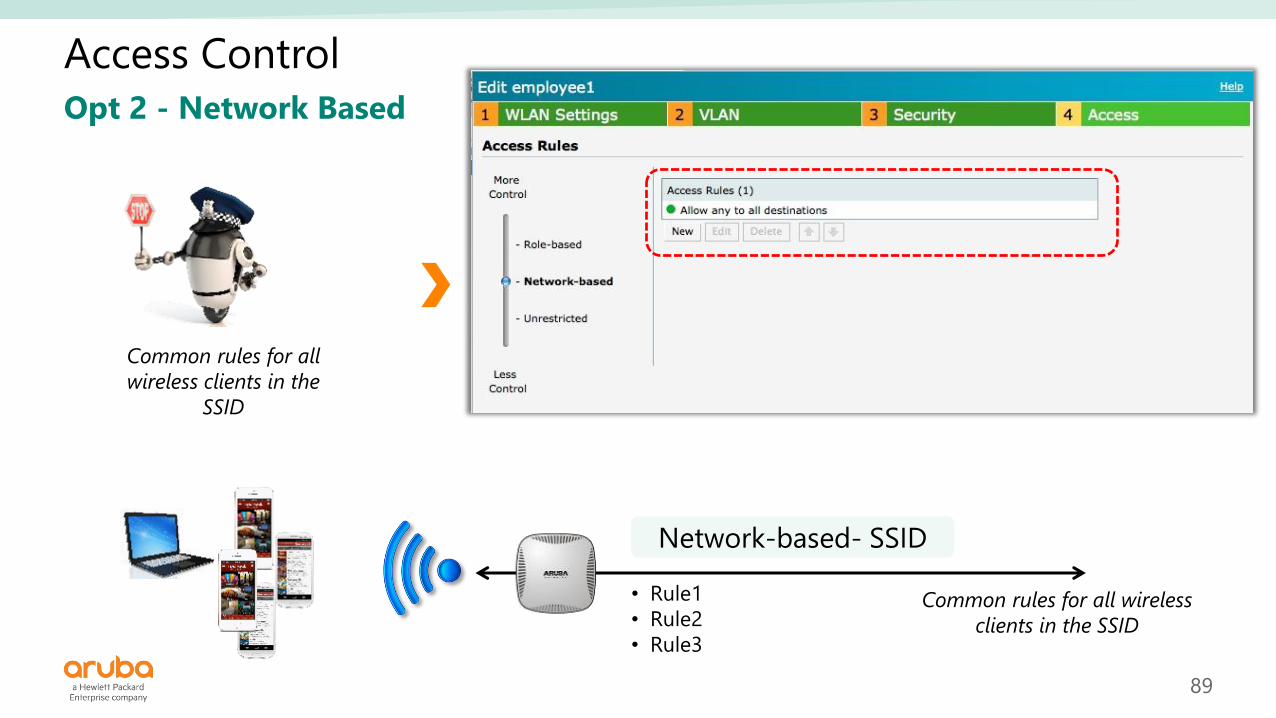
Access Control
Opt 2 - Network Based
• Rule1
• Rule2
• Rule3
Network-based- SSID
Common rules for all wireless
clients in the SSID
Common rules for all
wireless clients in the
SSID

90
Access Control with network parameters
Standard
Protocols

91
Access Control with Application parameter
Yahoo-games, Gmail-chat etc etc
Antivirus, Gaming, Webmail, etc
Shopping, Travel, Games, etc etc

92
Access Control with extended actions
Options depend on the
service type

93
Access Control
Opt 3 - Role Based
Role: employee
• Rule1
• Rule2
Role-based-SSID
Role: IT
• Rule 3
• Rule 4
Employee
10.12.12.5
IT
10.12.12.6
Enable access based on user
roles
employee1
IT
Enable access based on
user roles

94
Role - Derivation

95
Lab 03
• Consider:
▪ GG is the group number (01, 03, etc)
• Test wLAN connection:
▪ Connect a wireless client to the Employee
SSID.
▪ Try YouTube and social sites.
▪ Get statistics with AppRF.
• Create a Network Based rule:
▪ Edit the Employee SSID.
▪ Traffic filter for social sites.
▪ Traffic filter for streaming (YouTube)
• Test wLAN connection again:
▪ Connect a wireless client to the Employee
SSID.
▪ Try YouTube and social sites.
▪ Get statistics with AppRF.
Access Control

96
Captive Portal• Authentication
• Roles

97
In this module
• IAP’s captive portal characteristics.
• Configure internal acknowledged.
• Configure internal authenticated.
98
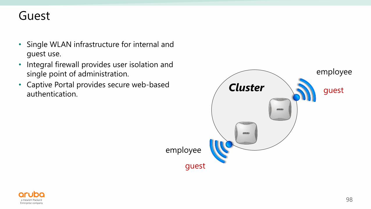
Guest
• Single WLAN infrastructure for internal and
guest use.
• Integral firewall provides user isolation and
single point of administration.
• Captive Portal provides secure web-based
authentication.Cluster
employee
employee
guest
guest

99
WLAN Wizards
SSID
Employee
Voice
Guest
VC Assigned
Default
Custom
Network Assigned
Default
Static
Dynamic
Enterprise
Personal
Open
Captive Portal
Role based
Network Base
Unrestricted

100
Configuring a Captive Portal SSID

101
IP address and VLAN Assignment

102
IAP Captive Portal - Options
• Internal - Authenticated
▪ The guest is authenticated with
the IAP’s internal database.
• Internal - Acknowledged
▪ Anonymous connection. The
guest must accept policies.
• External
▪ Required an external AAA server
(ClearPass, Radius).
▪ Uses a custom Facebook page as
an external captive portal
• None
▪ No conditions.

103
Opt 1 - Internal Acknowledged
Max size 16kB

104
Access Control

105
User acknowledged page
Internal Acknowledged

106
Opt 2 - Internal Authenticated

107
User authentication page
Internal Authenticated

108
User authentication page
Internal Authenticated - Alerts with Chrome or FireFox

109
Guest authenticated Role

110
Guest roles
Authenticated
Guest
Pre-Authentication

111
Pre-Authentication Role
Create your own
Pre-Authentication Role

112
External Captive Portal (ClearPass)

113
ClearPass Captive Portal Page

114
Lab 04
• Consider:▪ GG is the number group (01, 03, etc)
• Captive Portal with Internal Acknowledged:▪ Create a “Guest” SSID.
• Recommended name “portal_GG”
▪ IP Add and VLAN assignment:
• Network assigned
• Default
▪ In Security wizard use “Internal-Acknowledged”.
▪ Edit the Splash Page page:
• Texts
• Colors
• Logo
• Link redirect
▪ Configure control access.
• Test guest access:▪ Connect a guest user to the SSID.
▪ Authenticate.
▪ Open a window browser and surf.
▪ Review IP address.
Captive Portal

115
Lab 04 (cont)
• Captive Portal with Internal
Authenticated:
▪ Edit the “Guest” SSID.
▪ In Security wizard use “Internal-
Authenticated”.
▪ Edit the Splash Page page:
• Texts
• Colors
• Logo
• Link redirect
▪ Configure control access.
• Test guest access:
▪ Connect a guest user to the SSID.
▪ Authenticate.
▪ Open a window browser and surf.
▪ Review IP address.
Captive Portal

116
Management and Maintenance• AOS update
• Users
• Backup
• Operation modes
• AirWave

117
In this module
• IAP maintenance and operation
• Manager and users

118
Aruba OS update

119
Firmware download
support.arubanetworks.com
• Requires partner credentials
Instant AOS
Last versions

120
IAP AOS (Aruba Operating System)
• Pegasus:
▪ IAP 103, 114 and 115
▪ RAP 108 and 109
• Aries:
▪ RAP 155 and 155P
• Taurus:
▪ IAP 204, 205 and 205H
• Vela
▪ IAP 207
• Centaurus:
▪ IAP 214, 215, 224, 225, 274, 275 and 277
• Ursa
▪ IAP 304 and 305
• Hercules:
▪ IAP 314, 315, 324 and 325
• Lupus:
▪ IAP 334 and 335
• Cassiopeia *
▪ IAP 134 and 135
• Orion *
▪ IAP 92, 93, 104, 105 and 175
▪ RAP 3WN and 3WNP
* EoS

121
Firmware update

122
Firmware update (cont)
All IAPs in the cluster
must have the same
AOS version
Search and download
from the cloud
File in the PC (must be
compatible with the IAP
model)
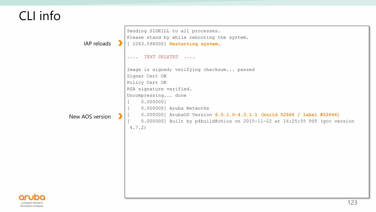
123
CLI infoSending SIGKILL to all processes.
Please stand by while rebooting the system.
[ 2263.596000] Restarting system.
.... TEXT DELETED ....
Image is signed; verifying checksum... passed
Signer Cert OK
Policy Cert OK
RSA signature verified.
Uncompressing... done
[ 0.000000]
[ 0.000000] Aruba Networks
[ 0.000000] ArubaOS Version 6.5.1.0-4.3.1.1 (build 52666 / label #52666)
[ 0.000000] Built by p4build@chios on 2015-11-22 at 16:25:55 PST (gcc version
4.7.2)
IAP reloads
New AOS version

124
Default factory configuration

125
Default Factory configuration
• Press and hold the Reset button.
• Turn-on the IAP (PoE/PoE+ switch, DC adapter).
• Wait 5 seconds, then release the button.
Opt 1 - Reset button
IAP 103 IAP 205HIAP 225
Reset
Button

126
Default Factory configuration apboot> factory_reset
Clearing state... Checking OS image and flags
Image is signed; verifying checksum... passed
Preserving image partition 0
Erasing flash sector @ 0x1ff80000.... done
Erased 1 sectors
.... TEXT DELETED ....
done
Purging environment... preserving os_partition (0)
Erasing flash...Writing to flash..................done
done
apboot>
apboot> purgeenv
preserving os_partition (0)
Erasing flash...Writing to flash..................done
apboot>
apboot> saveenv
Saving Environment to Flash...
Erasing flash...Writing to flash..................done
apboot>
apboot>
apboot> reset
Opt 2 - apboot (CLI)*
Process:
1. Turn on the IAP.
2. The console shows a three seconds
countdown. Press the <Enter> key to
interrupt the normal start-up.
3. The IAP starts the apboot mode.
4. Use the factory_reset and reset
commands.
5. Depending on the previous
deployment, it may require changes
in environment variables, if so, use
purgeenv, setenv, and saveenv
commands.

127
Default Factory configuration
Default Factory configuration
Opt 3 - Local Instant Manager

128
Configuration backup

129
Configuration backup and restore
instant.cfg
Local configuration backup

130
Operation modes

131
Terminology
CONTROLLERCAP
Mesh PointCAP &
Mesh Portal
AM
Spectrum
Analizer
INTERNET
or WAN
RAP RAP RAP &
Mesh Portal
VPN
INSTANTCAMPUS
Mesh Point
VC
IAP Cluster

132
Change the operation mode

133
Users

134
Administrator and operators

135
View Only and Guest Users
View Only- User
Guest- User

136
AirWave

137
AirWave
IAP Cluster
Instant UI
IAP Cluster
Instant UI
Mobility
Controller
ClearPass
AD / RADIUS
Enterprise HQ
Aruba
Airwave
WAN
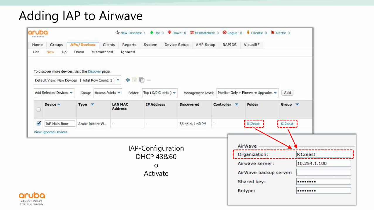
• Monitoring IAPs and Clusters.
• Client visibility.
• Reports and maps.
• GUI or template configuration.
138
Adding IAP to Airwave
IAP-Configuration
DHCP 43&60
o
Activate

139
Lab 05
• Review the options:
▪ AOS Update.
▪ Factory settings.
▪ Operation modes.
• Configure users:
▪ Change name and password for local
administrator.
▪ Create user "View Only“.
▪ Create user "Guest Registration Only“.
▪ Try users.
Management and Monitoring

140
Tools: • ARM
• Traffic analysis
141
In this module
• Understand ARM’s services and benefits.
142
Adaptive Radio Management

143
What is ARM?
• Adaptive Radio Management (ARM):
▪ RF Spectrum Management.
▪ Client match.
• Distributed algorithm approach:
▪ Best 802.11 channel.
▪ Transmit power settings.
• Highly-scalable & reliable RF environment:
▪ Dynamically Adapts to RF changing
environment.
▪ Over the Air updates.
• Features :
▪ RF Spectrum Management.
▪ Channel and Transmit Power.
▪ Voice and Client Aware.
▪ Load Aware.
▪ Band steering.
▪ Airtime Fairness.

144
ARM Scanning
1
10sec2
110msec
3
110msec
4
110msec • • •
Load Aware Scanning
Adjust scanning behavior in Idle Times or Busy times

145
Indexes
Interference Index
Co–channel interference
Coverage Index
All Aruba IAPs seen
on specific channel
Channel
selection
Power
selection
Ambient Noise
Phy/Mac errors
Client / Voice Aware
Interference + coverage

146
Channel and Power Selection
• Network learns:
▪ Optimal channel plan to
avoid interference.
▪ Optimal power levels to
avoid coverage holes.

147
Channel redistribution with ARM
Before ARM
After ARM

148
Band Steering
• Fingerprint clients that are 5GHz capable.
• Encourage these clients to move to 5GHz band by “hiding” APs in 2.4GHz band
from them (suppressing probe response from AP).
• Reserve 2.4GHz band for single-band clients.
Move clients to 5GHz band when capable
20MHz Channels 24 3
40MHz Channels 11 1X802.11b/g
802.11a/n
• Disabled
• Prefer 5 Ghz
• Force 5 Ghz
• Balance Bands

149
Airtime Fairness
• Allocation Policies:
▪ Default Access Disable air time allocation.
▪ Fair Access Allocate same time to all clients.
▪ Preferred Access Higher priority to Faster Clients without starving slower clients.
Improved RF performance

150
RF Neighborhood
-44dBm
-55dBm-60dBm
IAP 1IAP 2 IAP 3
IAP 4
-70dBm
-80dBm
-90dBm
IAP 5
IAP 6
VC
Client
Client Neighborhood
associated

151
Client Match
Steer Client
5 GHz Capable
Sticky Client
IAP Client load
Channel Utilization
Capacity Match
-44dBm
-55dBm-60dBm
IAP 1IAP 2 IAP 3
VC
Client
Client Neighborhood
associated

152
Load balance with Client Match
Without Client Match With Client Match

153
ARM configuration

154
Client Match Support Commands
Other CM Commands

155
AP Client Match Action
*************************************************************************************
7/10/2015 13:23:18 PM Target: IAP-9c Command: show ap client-match-actions
*************************************************************************************
Client Match Action Table
-------------------------
Station Old State New State Reason Radio Time
------- --------- --------- ------ ----- ----
00:23:14:ed:20:b0 Normal Home Band Steering 1 15:48:56
00:23:14:ed:20:b0 Home Done Deauth client for good 1 15:48:56
00:23:14:ed:20:b0 Done Normal Client match failed 1 15:48:57
00:23:14:ed:20:b0 Normal Deny I am not the better AP 1 15:49:13
00:23:14:ed:20:b0 Deny Failed Client match failed 1 15:49:13
00:23:14:ed:20:b0 Normal Home Band Steering 1 15:49:28
00:23:14:ed:20:b0 Normal Deny I am not the better AP 0 15:49:28
00:23:14:ed:20:b0 Home Done Deauth client for good 1 15:49:28
Normal :Working well
Home :Current AP found a better AP for the client
Deny :Current AP is not the better AP
Target :Current AP is the better AP
Voice :Ready to move, but client is doing voice
Refused :Too many clients try to move to me
Done :Current AP just deauth the client
Adopted :Client has moved to me successfully
Failed :Client Match attempts failed

156
ARM Support commands

157
ARM Neighbors Other ARM Commands

158
AppRF

159
Application visibility and control
On-Board DPI
• Depth - common apps
• Enterprise traffic
Cloud-Based Web Policy
Enforcement
• Breadth - less common apps
• Web traffic
❑ App category
❑ Individual app
❑ Web category
❑ Web reputation
❑ Allow/deny
❑ QoS
❑ Throttle
❑ Log
❑ Blacklist
GRANULAR VISIBILITY & CONTROL
Prioritize business critical apps
Block inappropriate content
Enforce per user/device/location

160
Applications, Web categories and Reputation
• 1957 applications supported on DPI engine (all popular applications)
▪ Applications are categorized into 21 discrete application categories
• 80 web categories from cloud service
▪ Each website can be classified into one or more web categories
▪ Web category and reputation scores are cached to avoid lookup
▪ Web Category and reputation scores are obtained from a cloud service provider (WebRoot /
BrightCloud).
• 5 web reputation values based on dynamic Web Reputation Index (WRI)
received from cloud service
Reputation WRI Score
Trustworthy 81-100
Low Risk 61-80
Moderate Risk 41-60
Suspicious 21-40
High Risk 1-20

161
Enabling AppRF visibility
• Best practice: enable “AppRF visibility” only if visibility is required (enforcement does NOT need this knob to be enabled).
• GUI:System -> General -> AppRF visibility
• CLI:AppRF-AP # configure t
AppRF-AP (config) # dpi
AppRF-AP (config) # end
AppRF-AP # commit apply

162
AppRF Dashboard

163
Additional services

164
Broadcast filtering
Broadcast configuration
Enable Advanced Options

165
Multicast Optimization
MTO and DMO are
disable by default
Enable Advanced Options
MTO: select the optimal rate for
sending broadcast and multicast
frames based on the lowest of unicast
rates across all associated clients.
DMO: convert multicast streams into
unicast streams over the
wireless link.

166
Interference immunity level
Level 2 by default
Enable Advanced Options

167
Lab 06
• Review options:
▪ ARM.
▪ AppRF.
▪ Multicast.
▪ Broadcast.
• Configure ARM:
▪ Steering.
▪ Airtime Fairness.
▪ Client Match.
▪ Get statistics.
Tools

168
Mesh

169
In this module
• Identify where a mesh connection it’s the best option.
• Configure a mesh.

170
Where do we need a mesh?
Prohibitive Cabling CostsEthernet and/or Fiber runs
are NOT practical
▪ Aruba’s Secure Enterprise Mesh technology is wire-free.
▪ Access points can be placed where needed.
▪ No fiber or UPT runs needed.
▪ Eliminates Ethernet cabling costs.
▪ Reduces the need for Ethernet ports.
▪ Centrally managed.

171
Mesh Components
• Mesh Portal IAP with wired uplink.
• Mesh Point IAP with wireless uplink.
• Mesh Link Wireless link between Mesh Portal and Mesh Link.
• Mesh ClusterIAPs group in mesh with at least one Mesh Portal.
Mesh Link
Switch LAN
Mesh Cluster
Mesh Point Mesh Portal

172
Mesh Setup
• In System window:
▪ Auto Join Mode = Enable
▪ Extended SSID = Disable
• Associate the slave IAPs (all of them will
receive configuration from the VC).
▪ In the intended Mesh Point use a static IP.
• Reboot the cluster.
• Turn off and disconnect the intended “Mesh
Point” IAP from the wired network.
• Install the Mesh Point IAP and turn it on.
• The Mesh Point attempts to connect with
the master through a wired link, then
changes to wireless link (mesh link).
▪ If the IAP finds a wireless link to the cluster
then will work as Mesh Point .
• Best practices:
▪ Maximum 2 hops.
▪ Use 5GHz band for uplink.
▪ In the Mesh Point use a static IP.
VC
Mesh Portal Mesh Point

173
Disable Extended SSID function
Turn off ‘Extended SSID’
Requires a cluster reboot
Enable Advanced Options
Auto Join mode enable
174
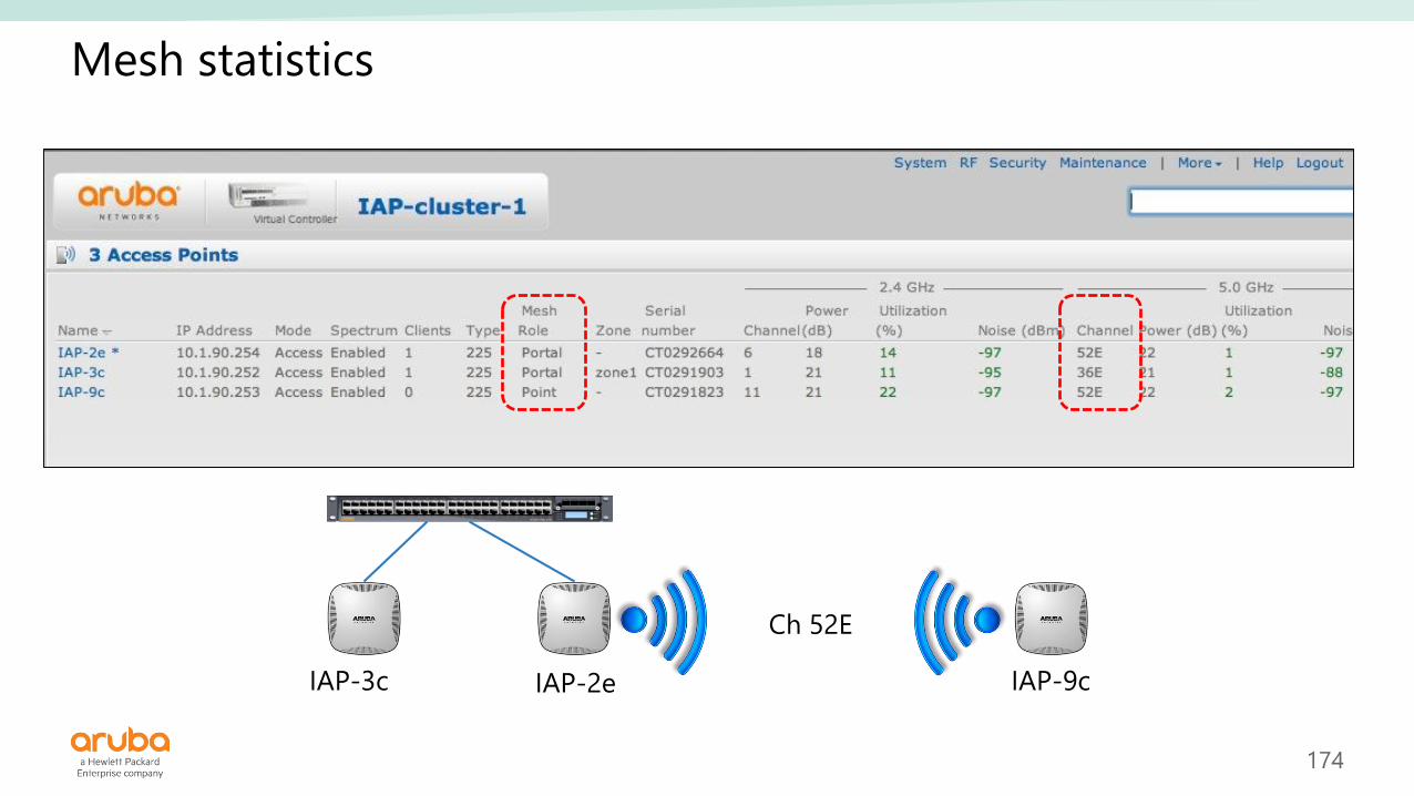
Mesh statistics
IAP-3c IAP-2e IAP-9c
Ch 52E

175
Troubleshooting
• Make sure that Mesh Portal and Mesh Point IAPs join the same cluster before
disconnect the Mesh Point.
• Check if Extended SSID is disabled (reboot is required).
• Check if there is a valid 5G SSID is configured.
• Check if there is Ethernet uplink on Mesh Point.
▪ It should not use Ethernet uplink on point.
• Check if master and salve use static channel.
▪ If yes, they should use the same channel.
• Check if point can see the Mesh Portal in its neighbor list:
▪ show ap mesh neighbor
• Check if point tries to establish Mesh Link:
▪ show ap mesh link

176
Uplink Configuration

177
Lab 07
• In System window:
▪ Disable Extended SSIDs
▪ Enable Auto Join
• Associate the intended Mesh Point
IAP into the Cluster:
▪ Configure a static IP address
• Reboot the Cluster
• Turn off and disconnect the Mesh
Point.
• Install the Mesh Point:
▪ It must not be connected to the LAN.
▪ Connect your PC to the console port.
▪ Turn it on.
• Statistics:
▪ Review the Mesh Point console logs.
▪ Get info in the Master (VC).
• Connect wireless users to the Mesh
Point, and test ping.
Mesh connection

178
Q & A

179
Thank you

180
Support info

181
MSR 900 configuration
[msr900_]display current-configuration#version 5.20, Release 2511#sysname msr900_#nat address-group 1 10.1.1.53 10.1.1.53#domain default enable system#telnet server enable#dar p2p signature-file flash:/p2p_default.mtd#port-security enable#password-recovery enable#acl number 2001rule 99 permit source 192.168.99.0 0.0.0.255rule 101 permit source 192.168.101.0 0.0.0.255rule 103 permit source 192.168.103.0 0.0.0.255rule 105 permit source 192.168.105.0 0.0.0.255rule 107 permit source 192.168.107.0 0.0.0.255rule 109 permit source 192.168.109.0 0.0.0.255rule 111 permit source 192.168.111.0 0.0.0.255rule 113 permit source 192.168.113.0 0.0.0.255rule 115 permit source 192.168.115.0 0.0.0.255rule 117 permit source 192.168.117.0 0.0.0.255rule 119 permit source 192.168.119.0 0.0.0.255
rule 121 permit source 192.168.121.0 0.0.0.255rule 300 deny#vlan 1#domain systemaccess-limit disablestate activeidle-cut disableself-service-url disable#user-group systemgroup-attribute allow-guest#local-user adminpassword cipher $c$3$NY5AtyyeYrV3Kth498IUWnxWUWMdOfplcBYJauthorization-attribute level 3service-type telnetservice-type web#cwmpundo cwmp enable#interface Cellular0/0async mode protocollink-protocol ppp#
182
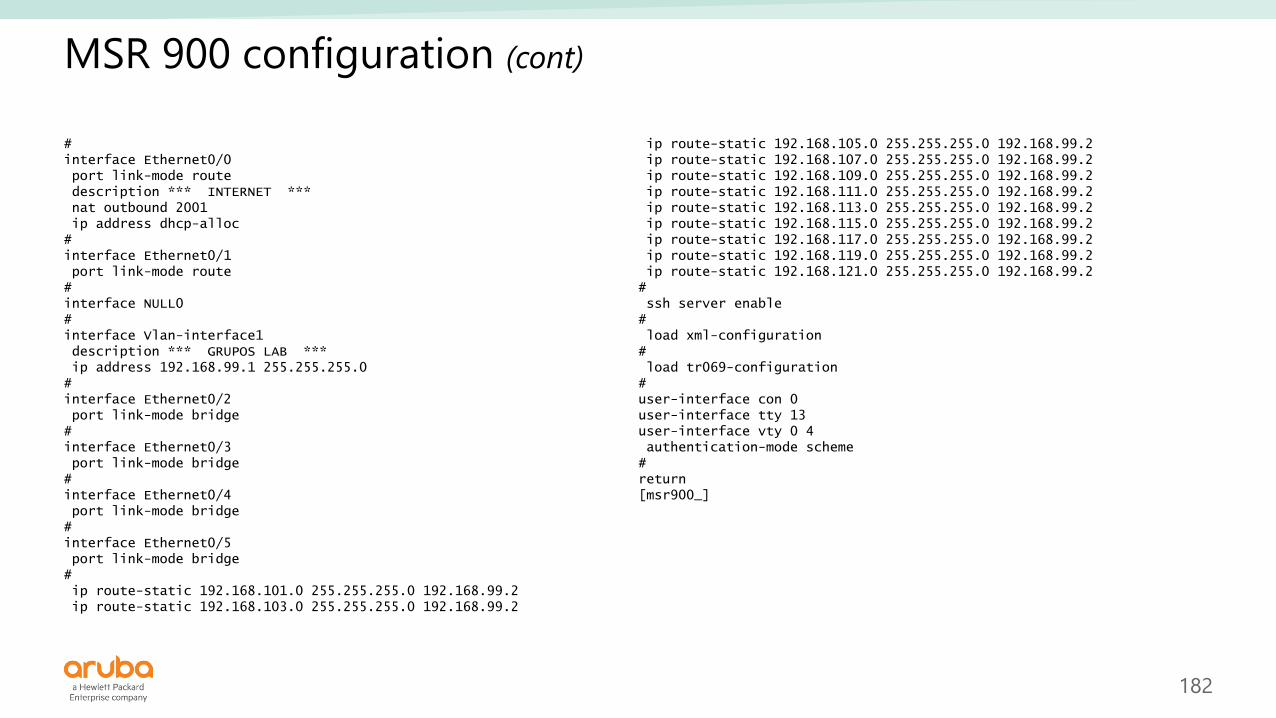
MSR 900 configuration (cont)
#interface Ethernet0/0port link-mode routedescription *** INTERNET ***nat outbound 2001ip address dhcp-alloc#interface Ethernet0/1port link-mode route#interface NULL0#interface Vlan-interface1description *** GRUPOS LAB ***ip address 192.168.99.1 255.255.255.0#interface Ethernet0/2port link-mode bridge#interface Ethernet0/3port link-mode bridge#interface Ethernet0/4port link-mode bridge#interface Ethernet0/5port link-mode bridge#ip route-static 192.168.101.0 255.255.255.0 192.168.99.2ip route-static 192.168.103.0 255.255.255.0 192.168.99.2
ip route-static 192.168.105.0 255.255.255.0 192.168.99.2ip route-static 192.168.107.0 255.255.255.0 192.168.99.2ip route-static 192.168.109.0 255.255.255.0 192.168.99.2ip route-static 192.168.111.0 255.255.255.0 192.168.99.2ip route-static 192.168.113.0 255.255.255.0 192.168.99.2ip route-static 192.168.115.0 255.255.255.0 192.168.99.2ip route-static 192.168.117.0 255.255.255.0 192.168.99.2ip route-static 192.168.119.0 255.255.255.0 192.168.99.2ip route-static 192.168.121.0 255.255.255.0 192.168.99.2#ssh server enable#load xml-configuration#load tr069-configuration#user-interface con 0user-interface tty 13user-interface vty 0 4authentication-mode scheme#return[msr900_]

183
HP 5130EI configuration
#[IAP_bc_v6.5]display current-configuration#version 7.1.045, Release 3106#sysname IAP_bc_v6.5#irf mac-address persistent timerirf auto-update enableundo irf link-delayirf member 1 priority 1#dhcp enable#lldp global enable#password-recovery enable#vlan 1description ** VLAN DEFAULT **#vlan 101description ** Grupo 01 **#vlan 103description ** Grupo 03 **#vlan 105description ** Grupo 05 **#vlan 107description ** Grupo 07 **
#vlan 109description ** Grupo 09 **#vlan 111description ** Grupo 11 **#vlan 113description ** Grupo 13 **#vlan 115description ** Grupo 15 **#vlan 117description ** Grupo 17 **#vlan 119description ** Grupo 19 **#vlan 121description ** Grupo 21 **#stp global enable#dhcp server ip-pool 101network 192.168.101.0 mask 255.255.255.0address range 192.168.101.3 192.168.101.9dns-list 8.8.8.8expired day 0 hour 8gateway-list 192.168.101.1#

184
HP 5130EI configuration (cont)
#dhcp server ip-pool 103network 192.168.103.0 mask 255.255.255.0address range 192.168.103.3 192.168.103.9dns-list 8.8.8.8expired day 0 hour 8gateway-list 192.168.103.1#dhcp server ip-pool 105network 192.168.105.0 mask 255.255.255.0address range 192.168.105.3 192.168.105.9dns-list 8.8.8.8expired day 0 hour 8gateway-list 192.168.105.1#dhcp server ip-pool 107network 192.168.107.0 mask 255.255.255.0address range 192.168.107.3 192.168.107.9dns-list 8.8.8.8expired day 0 hour 8gateway-list 192.168.107.1#dhcp server ip-pool 109network 192.168.109.0 mask 255.255.255.0address range 192.168.109.3 192.168.109.9dns-list 8.8.8.8expired day 0 hour 8gateway-list 192.168.109.1#dhcp server ip-pool 111network 192.168.111.0 mask 255.255.255.0address range 192.168.111.3 192.168.111.9
dns-list 8.8.8.8expired day 0 hour 8gateway-list 192.168.111.1#dhcp server ip-pool 113network 192.168.113.0 mask 255.255.255.0address range 192.168.113.3 192.168.113.9dns-list 8.8.8.8expired day 0 hour 8gateway-list 192.168.113.1#dhcp server ip-pool 115network 192.168.115.0 mask 255.255.255.0address range 192.168.115.3 192.168.115.9dns-list 8.8.8.8expired day 0 hour 8gateway-list 192.168.115.1#dhcp server ip-pool 117network 192.168.117.0 mask 255.255.255.0address range 192.168.117.3 192.168.117.9dns-list 8.8.8.8expired day 0 hour 8gateway-list 192.168.117.1#dhcp server ip-pool 119network 192.168.119.0 mask 255.255.255.0address range 192.168.119.3 192.168.119.9dns-list 8.8.8.8expired day 0 hour 8gateway-list 192.168.119.1#

185
HP 5130EI configuration (cont)
#dhcp server ip-pool 121network 192.168.121.0 mask 255.255.255.0address range 192.168.121.3 192.168.121.9dns-list 8.8.8.8expired day 0 hour 8gateway-list 192.168.121.1#dhcp server ip-pool defaultnetwork 192.168.99.0 mask 255.255.255.0address range 192.168.99.3 192.168.99.9dns-list 8.8.8.8expired day 0 hour 8gateway-list 192.168.99.1#interface NULL0#interface Vlan-interface1description ** Default VLAN **ip address 192.168.99.2 255.255.255.0#interface Vlan-interface101description ** Grupo 01 **ip address 192.168.101.1 255.255.255.0#interface Vlan-interface103description ** Grupo 03 **ip address 192.168.103.1 255.255.255.0#interface Vlan-interface105description ** Grupo 05 **ip address 192.168.105.1 255.255.255.0#
interface Vlan-interface107description ** Grupo 07 **ip address 192.168.107.1 255.255.255.0#interface Vlan-interface109description ** Grupo 09 **ip address 192.168.109.1 255.255.255.0#interface Vlan-interface111description ** Grupo 11 **ip address 192.168.111.1 255.255.255.0#interface Vlan-interface113description ** Grupo 13 **ip address 192.168.113.1 255.255.255.0#interface Vlan-interface115description ** Grupo 15 **ip address 192.168.115.1 255.255.255.0#interface Vlan-interface117description ** Grupo 17 **ip address 192.168.117.1 255.255.255.0#interface Vlan-interface119description ** Grupo 19 **ip address 192.168.119.1 255.255.255.0#interface Vlan-interface121description ** Grupo 21 **ip address 192.168.121.1 255.255.255.0#

186
HP 5130EI configuration (cont)
#interface GigabitEthernet1/0/1port access vlan 101poe enable#interface GigabitEthernet1/0/2port access vlan 101poe enable#interface GigabitEthernet1/0/3port access vlan 103poe enable#interface GigabitEthernet1/0/4port access vlan 103poe enable#interface GigabitEthernet1/0/5port access vlan 105poe enable#interface GigabitEthernet1/0/6port access vlan 105poe enable#interface GigabitEthernet1/0/7port access vlan 107poe enable#interface GigabitEthernet1/0/8port access vlan 107poe enable#
interface GigabitEthernet1/0/9port access vlan 109poe enable#interface GigabitEthernet1/0/10port access vlan 109poe enable#interface GigabitEthernet1/0/11port access vlan 111poe enable#interface GigabitEthernet1/0/12port access vlan 111poe enable#interface GigabitEthernet1/0/13port access vlan 113poe enable#interface GigabitEthernet1/0/14port access vlan 113poe enable#interface GigabitEthernet1/0/15port access vlan 115poe enable#interface GigabitEthernet1/0/16port access vlan 115poe enable#
187
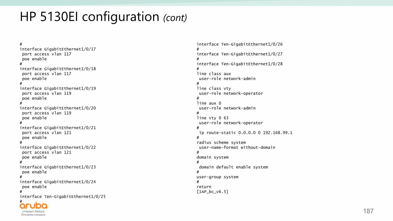
HP 5130EI configuration (cont)
#interface GigabitEthernet1/0/17port access vlan 117poe enable#interface GigabitEthernet1/0/18port access vlan 117poe enable#interface GigabitEthernet1/0/19port access vlan 119poe enable#interface GigabitEthernet1/0/20port access vlan 119poe enable#interface GigabitEthernet1/0/21port access vlan 121poe enable#interface GigabitEthernet1/0/22port access vlan 121poe enable#interface GigabitEthernet1/0/23poe enable#interface GigabitEthernet1/0/24poe enable#interface Ten-GigabitEthernet1/0/25#
interface Ten-GigabitEthernet1/0/26#interface Ten-GigabitEthernet1/0/27#interface Ten-GigabitEthernet1/0/28#line class auxuser-role network-admin#line class vtyuser-role network-operator#line aux 0user-role network-admin#line vty 0 63user-role network-operator#ip route-static 0.0.0.0 0 192.168.99.1#radius scheme systemuser-name-format without-domain#domain system#domain default enable system#user-group system#return[IAP_bc_v6.5]

![ScanJob - Ministry of Public Healthbps.moph.go.th/new_bps/sites/default/files/[6] 3rd... · 2017-06-12 · CONC THAMMASAT BUSINESS SCHOOL 10200 7 2560 Leadership Development and Strategic](https://static.fdocuments.in/doc/165x107/5ed496f4dc3bfa6a3e331140/scanjob-ministry-of-public-6-3rd-2017-06-12-conc-thammasat-business-school.jpg)