HP Virtual Connect Technology for HP Blade System
18
HP Virtual Connect technology for the HP BladeSystem c-Class technology brief, 4th edition Abstract .............................................................................................................................................. 2 Overview of Virtual Connect technology ................................................................................................. 2 Considerations when using Virtual Connect technology ............................................................................ 3 Creating server profiles ..................................................................................................................... 3 MAC/WWN addressing .................................................................................................................. 4 5 5 6 8 9 10 10 10 10 10 11 11 12 13 14 15 17 18 18 Virtual Connect domains ................................................................................................................... Virtual Connect management ................................................................................................................ Virtual Connect Enterprise Manager ................................................................................................... Virtual Connect Manager .................................................................................................................. Virtual Connect with Ethernet networks ................................................................................................... Uplink configurations ...................................................................................................................... Virtual LAN ................................................................................................................................... Link aggregation groups ................................................................................................................. Link failover ................................................................................................................................... Network loops ............................................................................................................................... NIC teaming ................................................................................................................................. Module stacking ............................................................................................................................ Virtual Connect Ethernet Modules..................................................................................................... Virtual Connect with Fibre Channel networks ........................................................................................ N_Port ID Virtualization (NPIV) ........................................................................................................ HP Virtual Connect Fibre Channel Modules for BladeSystem c-Class..................................................... Conclusion ........................................................................................................................................ For more information.......................................................................................................................... Call to action ....................................................................................................................................
Transcript of HP Virtual Connect Technology for HP Blade System

HP Virtual Connect technology for the HP BladeSystem c-Class technology brief, 4th edition
Abstract.............................................................................................................................................. 2 Overview of Virtual Connect technology................................................................................................. 2 Considerations when using Virtual Connect technology ............................................................................ 3
Creating server profiles..................................................................................................................... 3MAC/WWN addressing.................................................................................................................. 4
5
568
91010101010111112
131415
17
18
18
Virtual Connect domains ................................................................................................................... Virtual Connect management ................................................................................................................
Virtual Connect Enterprise Manager ................................................................................................... Virtual Connect Manager..................................................................................................................
Virtual Connect with Ethernet networks ................................................................................................... Uplink configurations...................................................................................................................... Virtual LAN ................................................................................................................................... Link aggregation groups ................................................................................................................. Link failover................................................................................................................................... Network loops............................................................................................................................... NIC teaming ................................................................................................................................. Module stacking ............................................................................................................................ Virtual Connect Ethernet Modules.....................................................................................................
Virtual Connect with Fibre Channel networks ........................................................................................ N_Port ID Virtualization (NPIV) ........................................................................................................ HP Virtual Connect Fibre Channel Modules for BladeSystem c-Class.....................................................
Conclusion........................................................................................................................................ For more information.......................................................................................................................... Call to action ....................................................................................................................................
2
Abstract As data center density and complexity increase, so do demands for IT efficiency and responsiveness. As a result, simplifying system interconnections becomes significantly more important. HP has developed the HP Virtual Connect architecture to boost the efficiency and productivity of data center server, storage, and network administrators.
This technology brief explains how Virtual Connect (VC) technology virtualizes the connections between the server and the network infrastructure (server-edge virtualization) so networks can communicate with pools of HP BladeSystem servers, allowing administrators to change servers in minutes instead of days or weeks.
Virtual Connect provides the following:
• Cleanly separates server enclosure administration from local area network (LAN) and storage area network (SAN) administration – maintains end-to-end connections of the preferred network fabric brands – relieves LAN and SAN administrators from routine server-centric tasks
• Makes servers ready for rapid change at any time, so that server administrators can add, move, or replace servers without impacting production LAN and SAN availability, reducing costs and time to deploy
• Offers central management of one Virtual Connect domain through the Virtual Connect Manager (VCM) or hundreds of domains through the Virtual Connect Enterprise Manager (VCEM) – Group-based management of Virtual Connect domains increases infrastructure consistency, limits
configuration errors, and enables rapid change management across multiple enclosures – VCEM repository provides efficient address administration eliminating the risk of address conflicts
Overview of Virtual Connect technology Virtual Connect is an industry standard-based implementation of server-edge virtualization and provides capabilities that enable HP FlexFabric. It puts an abstraction layer between the servers and the external networks so the LAN and SAN see a pool of servers rather than individual servers (Figure 1). Once the LAN and SAN connections are physically made to the pool of servers, the server administrator uses Virtual Connect management tools (Virtual Connect Enterprise Manager or Virtual Connect Manager) to create an I/O connection profile for each server.

Figure 1. This illustration depicts Server-edge virtualization.
The I/O connection profile, or server profile, provides the linkage between the server and the connections defined in Virtual Connect. Server profiles are created within Virtual Connect management tools and contain information about server addresses, connections, and boot parameters.
HP Virtual Connect modules are required to activate the full server-edge virtualization across the system. The underlying Virtual Connect management capabilities run on a processor in the Ethernet module, so each BladeSystem enclosure must have at least one Virtual Connect Ethernet module. No special mezzanine cards are required for the server blades; HP Virtual Connect works with the standard Ethernet NICs and Fibre Channel (FC) HBAs that are available with HP BladeSystem c-Class server blades.
Considerations when using Virtual Connect technology Using Virtual Connect management tools, the server administrator can create bay-specific I/O profiles, assign unique Media Access Control (MAC) addresses and World Wide Names (WWNs) to these profiles, and manage the profiles locally. Network and storage administrators can establish all LAN and SAN connections once during deployment and need not make connection changes later if servers are changed. As servers are deployed, added, or changed, Virtual Connect keeps the I/O profile for that LAN and SAN connection constant. A Virtual Connect server profile can be created and deleted as required.
Creating server profiles To create server connection profiles, the LAN and SAN administrators must first define the networks and subnets that will be available to the server administrator. Server profiles contain information
3
4
about server MAC and WWN addresses, connections to LANs and SANs for each Network Interface Controller (NIC) and FC Host Bus Adapter (HBA), Virtual Local Area Networks (VLAN), as well as Preboot eXecution Environment (PXE) and/or SAN Boot parameters, and profile failover resources. Once a server profile is assigned to a server blade in a specific bay and the server is powered on, the connection specifics of that profile are applied to that server blade.
Virtual Connect server connection profiles are assigned to BladeSystem enclosure bays rather than to individual servers, making the system more flexible and reliable:
• If a physical server is replaced, the MAC and WWN assignments for the enclosure bay remain constant, and the change is invisible to the network.
• If a server connection profile is moved from one enclosure bay to another, the MAC, WWN, boot-from-SAN definitions and associated workloads move with the profile, presenting a cost-effective solution for rapid system recovery or for reassigning server workloads.
• By applying server profiles to empty enclosure bays, administrators can pre-populate LAN and SAN network assignments for rapid server deployment.
NOTE: A server blade must be powered off to assign or remove a server profile.
MAC/WWN addressing No virtual devices are created; the WWNs and MAC addresses are real. They are the only WWNs and MAC addresses seen by the system, the Operating System (OS), and the networks. Although the hardware ships with default MAC addresses and WWNs, Virtual Connect resets the MAC addresses and WWNs prior to boot, so PXE/SAN boot and all operating systems will see only the Virtual Connect managed values.
During Virtual Connect environment setup, the administrator can select MAC/WWN from one of the following groups:
• Factory default MACs/WWNs • A specific, user-defined range of MACs/WWNs • One of several HP pre-defined ranges of MACs/WWNs
Using factory default MAC addresses is not recommended because they cannot be moved to another server blade. System administrators must be careful to use each reserved range only once within their enterprise environments.
NOTE: HP is registered with the appropriate standards bodies as an Ethernet and FC vendor and WWN ranges for exclusive use with Virtual Connect. These reserved ranges will never be used as factory default MACs/WWNs on any hardware.
If a server is moved from a Virtual Connect managed enclosure to an unmanaged enclosure, the local MAC addresses and WWNs automatically return to the original factory defaults. If a server is removed from a server bay within a Virtual Connect domain and is plugged into another bay in the

same domain or into a bay in a different domain, it will be assigned the new set of addresses appropriate for that server bay location.
Virtual Connect domains A Virtual Connect domain includes up to four BladeSystem enclosures, configured with Virtual Connect, that connect to common LAN and SAN environments.
Administrators use either the Virtual Connect Manager or Virtual Connect Enterprise Manager to create Virtual Connect domains. When the administrators create a domain, the default network connection is immediately terminated. Specific network connections will then need to be created.
Environments that use Virtual Connect Enterprise Manager can create groups of Virtual Connect domains that share common network connections, and are all administered with a common configuration profile. Therefore, Virtual Connect domains can be added rapidly and modified with a high level of consistency.
Virtual Connect management To set up and administer the address pools, connection profiles, and other Virtual Connect resources, HP provides management options for large and small environments: HP Virtual Connect Enterprise Manager and HP Virtual Connect Manager (Figure 2).
Figure 2. This illustration depicts HP Virtual Connect management options for small and large environments.
5

Virtual Connect Enterprise Manager HP Virtual Connect Enterprise Manager (VCEM) is a highly scalable software solution that centralizes network connection management and workload mobility for thousands of servers that use Virtual Connect to connect to data and storage networks (Figure 3).
Figure 3. This illustration shows the Virtual Connect Enterprise Manager homepage.
Virtual Connect Enterprise Manager (VCEM) provides the following core capabilities:
• Single intuitive console controls up to 250 Virtual Connect domains (up to 1000 BladeSystem enclosures and 16,000 servers)1 with VCEM v6.00 or greater when used with Virtual Connect Ethernet multi-enclosure domain configurations
• Central repository administers over 256K MAC addresses and WWNs for server-to-network connectivity – simplifies address assignments and eliminates the risk of conflicts
• Group-based management of Virtual Connect domains using common configuration profiles – increases infrastructure consistency, limits configuration errors, simplifies enclosure deployment and enables configuration changes to be pushed to multiple Virtual Connect domains
• Scripted and manual movement of server connection profiles and associated workloads between BladeSystem enclosures – system administrators can add, change and replace servers across the data center in minutes without impacting production LAN and SAN availability
• Automated failover of server connection profiles to user-defined spare servers
1 One Domain = up to 4 enclosures in a VC multiple enclosure configuration; 250 domains x 4 enclosures = 1000 enclosures x 16 servers per enclosure = 16,000 servers
6
7
• Seamlessly integrates with existing Virtual Connect environments – discovers and aggregates Virtual Connect domain resources into the VCEM console and address repository
• Licensed per c-Class enclosure – simplifies deployment and enables timely support for current and future BladeSystem and Virtual Connect hardware
NOTE: Virtual Connect Enterprise Manager is licensed per BladeSystem c-Class enclosure, with separate options for c3000 and c7000 enclosures. A VCEM license is required for each enclosure to be managed in both single and multi-enclosure domain configurations.
Using VCEM, system administrators can upgrade and/or replace a server by simply reassigning its Virtual Connect server connection profile to an alternate server in another enclosure bay or another enclosure (Figure 4). This simple example illustrates a profile move from “Server A” to “Server C” using VCEM. Note that the LANs associated with each uplink port and the contents of the Virtual Connect server profile remain the same; only the location of the profile has changed. When a Virtual Connect server connection profile is moved, the associated MAC, WWN, boot from SAN parameters and related workload always move with the profile.
Profile movement can be initiated manually from all Virtual Connect management tools. Virtual Connect Enterprise Manager can automate this entire process using its profile failover and spare server allocation features, and has the ability to move server profiles to any other domain in the same Virtual Connect Domain Group, whether it is in the same rack, across the datacenter or at another site. Profile movement and failover can be used to provide cost-effective server blade recovery, perform proactive hardware maintenance with reduced downtimes, and control rapid server repurposing to meet changing workload and application priorities.
When moving Virtual Connect server profiles, the fastest completion times are achieved when the corresponding source and target servers are configured to boot-from-SAN. The automated profile failover functionality delivered in VCEM requires a boot-from-SAN environment.
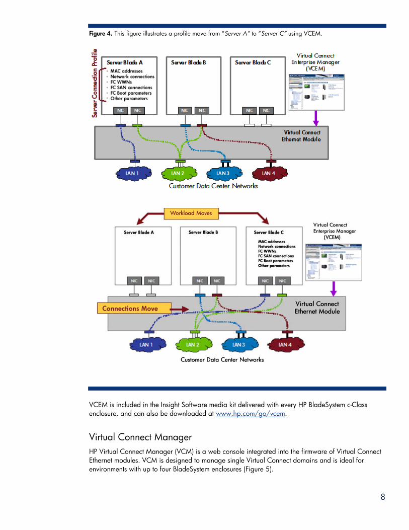
Figure 4. This figure illustrates a profile move from “Server A” to “Server C” using VCEM.
VCEM is included in the Insight Software media kit delivered with every HP BladeSystem c-Class enclosure, and can also be downloaded at www.hp.com/go/vcem.
Virtual Connect Manager HP Virtual Connect Manager (VCM) is a web console integrated into the firmware of Virtual Connect Ethernet modules. VCM is designed to manage single Virtual Connect domains and is ideal for environments with up to four BladeSystem enclosures (Figure 5).
8
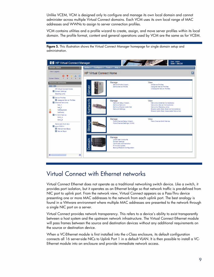
Unlike VCEM, VCM is designed only to configure and manage its own local domain and cannot administer across multiple Virtual Connect domains. Each VCM uses its own local range of MAC addresses and WWNs to assign to server connection profiles.
VCM contains utilities and a profile wizard to create, assign, and move server profiles within its local domain. The profile format, content and general operations used by VCM are the same as for VCEM.
Figure 5. This illustration shows the Virtual Connect Manager homepage for single domain setup and administration.
Virtual Connect with Ethernet networks Virtual Connect Ethernet does not operate as a traditional networking switch device. Like a switch, it provides port isolation, but it operates as an Ethernet bridge so that network traffic is pre-defined from NIC port to uplink port. From the network view, Virtual Connect appears as a Pass-Thru device presenting one or more MAC addresses to the network from each uplink port. The best analogy is found in a VMware environment where multiple MAC addresses are presented to the network through a single NIC port on a server.
Virtual Connect provides network transparency. This refers to a device’s ability to exist transparently between a host system and the upstream network infrastructure. The Virtual Connect Ethernet module will pass frames between the source and destination devices without any additional requirements on the source or destination device.
When a VC-Ethernet module is first installed into the c-Class enclosure, its default configuration connects all 16 server-side NICs to Uplink Port 1 in a default VLAN. It is then possible to install a VC-Ethernet module into an enclosure and provide immediate network access.
9
10
If the VC Domain is deleted after the VC-Ethernet module has been configured with specific LAN and VLAN connections defined, the default configuration connecting all 16 server-side NICs to Uplink Port 1 will be reinstated until a new VC domain is created.
Uplink configurations Virtual Connect supports a variety of uplink types and uplink speeds. These uplinks can be configured in a variety of ways:
• Simple, single cable uplink with one VLAN • Multiple uplink ports aggregated in an IEEE 802.3ad Link Aggregation Control Protocol (LACP) link
aggregation group (dynamic port channel or port trunk) • Multiple VLANs sharing a single port or port-trunk, IEEE 802.1Q leveraging single or aggregated
ports
NOTE: Virtual Connect does not participate in Spanning Tree protocol on network uplinks.
Virtual LAN Virtual Connect is fully VLAN-aware. VLAN-tagged frames can be interpreted by the HP 1/10-Gb Virtual Connect module using a Shared Uplink Set and passed to the appropriate Virtual Connect Network. Alternatively, VLAN-tagged frames can be passed through the Virtual Connect Network for interpretation by the host.
Link aggregation groups Virtual Connect provides load balancing over Link Aggregation Groups. Link Aggregation Groups load balance traffic by source and destination MAC and/or source and destination IP addresses. Virtual Connect understands LACP so it can handle bundled network uplinks to ports in the same Virtual Connect module. Link aggregation is only possible for ports on the same Virtual Connect module connected to the same upstream switch. Virtual Connect does not support aggregating ports between multiple Virtual Connect modules even in the same VC Domain.
Link failover Virtual Connect facilitates link failover by allowing Virtual Connect networks to leverage ports on multiple Virtual Connect modules in the same VC Domain. Depending on its configuration, a Virtual Connect network will transparently shift its upstream communication to a port on the same module or on a different module in the event of a link failure.
Network loops The Virtual Connect module prevents network loops by making sure that there is only one active uplink (or uplink link aggregation group) for any single network at any one time so traffic cannot loop through from uplink to uplink. In addition, Virtual Connect automatically discovers all the internal stacking links and uses an internal loop prevention algorithm to ensure there are no loops caused by the stacking links. None of the internal loop prevention traffic ever shows up on uplinks or moves to the external switch.
NIC teaming Virtual Connect supports most features available in the HP NIC Teaming Software. With the HP NIC Teaming software a user can introduce a variety of host-based features including NIC fault-tolerance and Transmit Load Balancing.
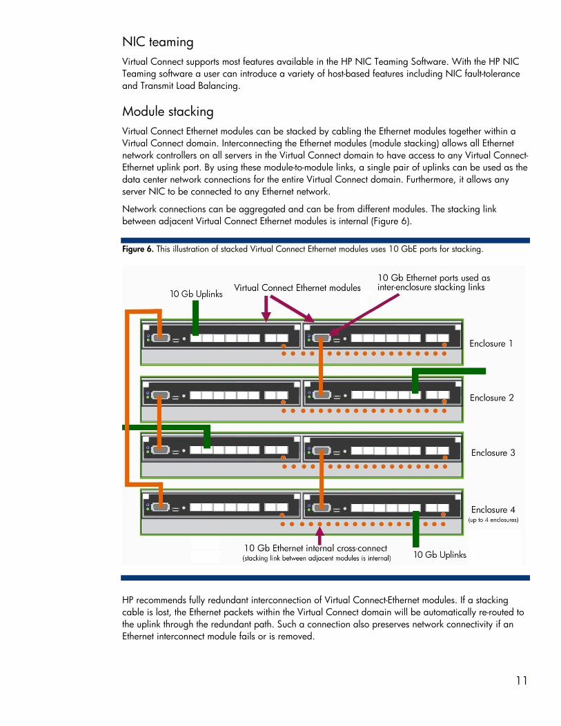
Module stacking Virtual Connect Ethernet modules can be stacked by cabling the Ethernet modules together within a Virtual Connect domain. Interconnecting the Ethernet modules (module stacking) allows all Ethernet network controllers on all servers in the Virtual Connect domain to have access to any Virtual Connect-Ethernet uplink port. By using these module-to-module links, a single pair of uplinks can be used as the data center network connections for the entire Virtual Connect domain. Furthermore, it allows any server NIC to be connected to any Ethernet network.
Network connections can be aggregated and can be from different modules. The stacking link between adjacent Virtual Connect Ethernet modules is internal (Figure 6).
Figure 6. This illustration of stacked Virtual Connect Ethernet modules uses 10 GbE ports for stacking.
HP recommends fully redundant interconnection of Virtual Connect-Ethernet modules. If a stacking cable is lost, the Ethernet packets within the Virtual Connect domain will be automatically re-routed to the uplink through the redundant path. Such a connection also preserves network connectivity if an Ethernet interconnect module fails or is removed.
11

12
Virtual Connect Ethernet Modules The Virtual Connect Ethernet modules plug directly into the interconnect bays of the HP BladeSystem c-Class enclosure. The modules can be placed side by side for redundancy and can connect selected server Ethernet ports to specific data center networks and provide a connection to any data center switch environment.
For a single-module configuration, install the Virtual Connect Ethernet Module in interconnect bay one and for a redundant configuration, install the second module in interconnect bay two. A configuration of Virtual Connect and non-Virtual Connect interconnect modules in horizontally adjacent bays is not supported.
NOTE: When installing an HP Virtual Connect Ethernet Module into an enclosure with existing servers, do not change the MAC addresses of the NICs residing in servers that were installed prior to Virtual Connect module deployment. Ensure that all Integrated Lights Out (iLO) management processors and the HP Virtual Connect Ethernet Modules have received IP addresses. Without IP addresses on all modules, Virtual Connect will not operate properly.
The following modules are available as of this writing:
• HP Virtual Connect Flex-10 10GB Ethernet Module for BladeSystem c-Class • HP 1/10Gb-F Virtual Connect Ethernet Module for BladeSystem c-Class
For the most up-to-date product information, see the HP website at www.hp.com/go/virtualconnect.
Virtual machine applications often require increased network connections per server. Virtual Connect Flex-10 can optimize networks by allowing administrators to fine-tune network bandwidth at the server edge by dividing each 10Gb network connection into four independent physical FlexNIC server connections. Each FlexNIC can be configured from 100 Mb up to 10 Gb, allowing just the right amount of network bandwidth based on application needs. For more detailed information about HP Virtual Connect Flex-10, review the HP Flex-10 technology brief at http://h20000.www2.hp.com/bc/docs/support/SupportManual/c01608922/c01608922.pdf.
The HP 1/10Gb-F Virtual Connect Ethernet Module appears as a pass-thru device to the network, yet provides all the key benefits of integrated switching including high performance 1Gb and 10Gb Fiber Optic uplinks to the data center switch, port aggregation, failover, VLAN tagging, and stacking. The Virtual Connect Fiber Ethernet Module manages and administers server profiles that can be pre-defined and deployed anywhere within a Virtual Connect domain. This allows servers to come online quickly and easily without having to coordinate with network administrators.
As outlined in Table 1, each Virtual Connect Ethernet Module has the following characteristics:
• Sixteen Ethernet downlinks (1Gb or 10Gb) to servers (connected across the signal midplane in the enclosure)
• Eight Ethernet uplinks (copper or fiber) to external networks • One or two CX4 uplinks to connect to core switches or to stack Virtual Connect modules • One or two internal cross-connects, or inter-switch links, across the signal midplane in the enclosure
for a failover connection between Virtual Connect modules • Support for existing 802.1 bridging specifications (802.1AB, 802.1Q, IEEE 802.2, and 802.3ad).
13
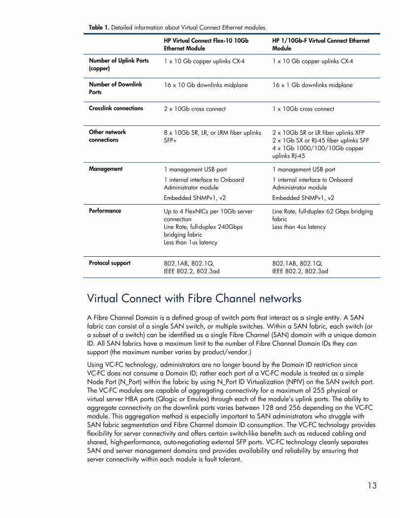
Table 1. Detailed information about Virtual Connect Ethernet modules
HP Virtual Connect Flex-10 10Gb Ethernet Module
HP 1/10Gb-F Virtual Connect Ethernet Module
Number of Uplink Ports (copper)
1 x 10 Gb copper uplinks CX-4
1 x 10 Gb copper uplinks CX-4
Number of Downlink Ports
16 x 10 Gb downlinks midplane
16 x 1 Gb downlinks midplane
Crosslink connections 2 x 10Gb cross connect
1 x 10Gb cross connect
Other network connections
8 x 10Gb SR, LR, or LRM fiber uplinks SFP+
2 x 10Gb SR or LR fiber uplinks XFP 2 x 1Gb SX or RJ-45 fiber uplinks SFP 4 x 1Gb 1000/100/10Gb copper uplinks RJ-45
Management 1 management USB port
1 internal interface to Onboard Administrator module
Embedded SNMPv1, v2
1 management USB port
1 internal interface to Onboard Administrator module
Embedded SNMPv1, v2
Performance
Up to 4 FlexNICs per 10Gb server connection Line Rate, full-duplex 240Gbps bridging fabric Less than 1us latency
Line Rate, full-duplex 62 Gbps bridging fabric Less than 4us latency
Protocol support 802.1AB, 802.1Q, IEEE 802.2, 802.3ad
802.1AB, 802.1Q, IEEE 802.2, 802.3ad
Virtual Connect with Fibre Channel networks A Fibre Channel Domain is a defined group of switch ports that interact as a single entity. A SAN fabric can consist of a single SAN switch, or multiple switches. Within a SAN fabric, each switch (or a subset of a switch) can be identified as a single Fibre Channel (SAN) domain with a unique domain ID. All SAN fabrics have a maximum limit to the number of Fibre Channel Domain IDs they can support (the maximum number varies by product/vendor.)
Using VC-FC technology, administrators are no longer bound by the Domain ID restriction since VC-FC does not consume a Domain ID; rather each port of a VC-FC module is treated as a simple Node Port (N_Port) within the fabric by using N_Port ID Virtualization (NPIV) on the SAN switch port. The VC-FC modules are capable of aggregating connectivity for a maximum of 255 physical or virtual server HBA ports (Qlogic or Emulex) through each of the module’s uplink ports. The ability to aggregate connectivity on the downlink ports varies between 128 and 256 depending on the VC-FC module. This aggregation method is especially important to SAN administrators who struggle with SAN fabric segmentation and Fibre Channel domain ID consumption. The VC-FC technology provides flexibility for server connectivity and offers certain switch-like benefits such as reduced cabling and shared, high-performance, auto-negotiating external SFP ports. VC-FC technology cleanly separates SAN and server management domains and provides availability and reliability by ensuring that server connectivity within each module is fault tolerant.
14
In order to use Virtual Connect Fibre Channel modules, administrators must have the following:
• An HP Fibre Channel mezzanine adapter with the appropriate supported firmware and boot BIOS installed in at least one of the c-Class blades within the chassis
• At least one Virtual Connect Ethernet module installed in interconnect bay one • An available interconnect bay for the VC-FC module(s) – VC-FC modules are supported in
interconnect bays 3 thru 8 in the HP BladeSystem c7000 enclosure and interconnect bays 3 and 4 in the HP BladeSystem c3000 enclosure
• VC-FC module uplink ports must be attached to NPIV-capable SAN switches, and NPIV must be enabled on the SAN switch ports. – Most enterprise class SAN switches today support NPIV – however, a firmware upgrade may be
required. Please refer to the SAN switch vendor documentation for more details. – If switch based zoning is in place, using NPIV will require soft zoning (zoning by WWN) to
ensure that multiple connections sharing a single NPIV switch port will be zoned.
Virtual Connect Fibre Channel modules do not have any mechanisms within the modules themselves to support VC-FC module failover. HP recommends deploying VC-FC modules in pairs in a side-by-side configuration (for example, interconnect bays 3 and 4, or 5 and 6). In doing so, standard Fibre Channel redundant solutions can be implemented at the OS layer in order to support multiple paths either in an active/passive or active/active solution. (Active/passive and active/active solutions are dependent upon the OS layer, HBA drivers, and failover support software.)
N_Port ID Virtualization (NPIV) Virtual Connect adheres to the ANSI T-11 standards that define all Fibre Channel technologies, including NPIV. NPIV is an industry-standard FC protocol that provides a means to assign multiple FC addresses on the same physical link. Specifically, it provides an FC facility for assigning multiple N_Port IDs to a single N_Port which allows multiple distinguishable entities on the same physical port. In other words, it makes a single FC port appear as multiple virtual ports, each having its own N_Port ID and virtual WWN.
The NPIV protocol requires two participating ports:
• N_Port, typically an HBA or any device that acts as an NPIV gateway. The N_Port communicates with a Fibre Channel fabric for requesting port addresses and subsequently registering with the fabric.
• F_Port or a fabric port (generally an FC switch). The F_Port assigns the WWN addresses and provides fabric services for the N_Port.
This protocol has been well defined in T-112 standards (FC-DA and FC-LS) and both the N_Port and FC switch should comply with this protocol for the NPIV-based technology in Virtual Connect to function properly.
Any HBA or any special device that is capable of N_Port functionality can connect to an NPIV-capable switch and can perform multiple logins on a single physical link to which it is attached. NPIV enables several possible solutions such as HBA and server virtualization and gateway connectivity for multiple servers without adding an additional FC Domain to an existing FC fabric.
During the fabric login sequence, the VC-FC modules convert regular N_Port fabric login frames to comply with the NPIV standard. Once that is complete, the frames are passed through the VC-FC modules without any changes. Since each server HBA port still logs into the SAN fabric with its port WWN and receives back a port ID from the switch name server, all of the standard WWN-based
2 The web site for the Technical Committee T-11 is http://www.t11.org/index.html. This is the committee within the INCITS (International Committee for Information Technology Standards) responsible for Fibre Channel Interfaces.

15
SAN zoning is supported. HP recommends that customers use soft or WWN-based zoning whenever Virtual Connect Fibre Channel is used. However, customers could use port-based zoning, but they will need to restrict movement of Virtual Connect server profiles among servers that map to the same SAN switch port.
Traditionally, storage resources have been tied to a physical HBA and could not be provisioned to the virtual machines using the SAN administrator’s tools of choice like zoning and selective storage presentation. HP Virtual Connect Fibre Channel Modules remove this storage management limitation, facilitating multiple HBA WWNs on the physical server. Each virtual machine can have its own unique WWN and it remains associated with that virtual machine even as the virtual machine is moved. Now SAN administrators can manage and provision storage to virtual HBAs, up to 128 per server blade, with the same methods and quality of service as physical HBAs.
HP Virtual Connect Fibre Channel Modules for BladeSystem c-Class The Virtual Connect modules (single-wide, hot-pluggable modules) plug directly into the interconnect bays of the HP BladeSystem c-Class enclosure. The modules can be placed side by side for redundancy into interconnect bays 3 through 8 of the HP BladeSystem c7000 enclosure and bays 3 and 4 of the HP BladeSystem c3000 enclosure. HP c-Class HBA port mappings are hard-wired in the c-Class midplane to a predetermined interconnect bay side. Therefore, with a dual-port mezzanine adapter in a c-Class server blade, port one will map to the left side interconnect bay, and port two will map to the matching interconnect bay on the right side of the chassis. This design allows for maximum availability, reliability, and performance.
The following modules are available as of this writing:
• HP Virtual Connect 4Gb Fibre Channel Module for BladeSystem c-Class • HP Virtual Connect 8Gb 20-Port Fibre Channel Module for BladeSystem c-Class • HP Virtual Connect 8Gb 24-Port Fibre Channel Module for BladeSystem c-Class
An HP VC-FC Module can aggregate up to 16 physical FC HBA ports (at the back end connected through the enclosure mid-plane). Each module has four or eight uplink ports that connect to an external FC SAN fabric. The uplink ports accept short wave or long wave 4- or 8-Gb small form-factor pluggable (SFP) optical transceivers, depending on the module. The SFPs can operate at 1, 2, 4, or 8 Gb/s as needed based on the SAN infrastructure.
Each of the uplink ports is capable of aggregating between zero and 255 physical or virtual server FC HBA ports. The oversubscription ratio will depend on the number of the available uplink ports and active server HBA ports. By default, all VC-FC module uplink ports are grouped into a single port group, distributing connectivity from all server blades in the enclosure. If a port in the group becomes unavailable, servers logged in through that port are reconnected to the fabric through the remaining ports in the group, resulting in auto-failover.
HP VC-FC modules appear as pass-thru devices to the SAN fabric (Figure 7). Any changes to the server are transparent to its associated network. This separates the servers from the SAN and relieves SAN administrators from server maintenance.
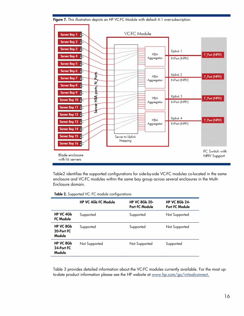
Figure 7. This illustration depicts an HP VC-FC Module with default 4:1 over-subscription.
Table2 identifies the supported configurations for side-by-side VC-FC modules co-located in the same enclosure and VC-FC modules within the same bay group across several enclosures in the Multi-Enclosure domain.
Table 2. Supported VC- FC module configurations
HP VC 4Gb FC Module HP VC 8Gb 20-Port FC Module
HP VC 8Gb 24-Port FC Module
HP VC 4Gb FC Module
Supported Supported Not Supported
HP VC 8Gb 20-Port FC Module
Supported Supported Not Supported
HP VC 8Gb 24-Port FC Module
Not Supported Not Supported Supported
Table 3 provides detailed information about the VC-FC modules currently available. For the most up-to-date product information please see the HP website at www.hp.com/go/virtualconnect.
16

17
Table 3. VC- FC module capabilities
HP VC 4Gb FC Module
HP VC 8Gb 20-Port FC Module
HP VC 8Gb 24-Port FC Module
Uplink Port Capabilities 4Gb (4/2/1/Auto)
8Gb (8/4/2/Auto) 8Gb (8/4/2/Auto)
Downlink Port Capabilities 4Gb (4/2/1/Auto)
8Gb (8/4/2/1/Auto) 8Gb (8/4/21/Auto)
Number of Uplink Ports 4 4 8
Number of Transceivers (included) 4 SFP None 2 SFP+
NPIV Logins per Uplink Port 255 255 255
NPIV Logins per Downlink Port 128 128 255
Minimum Oversubscription 4:1 4:1 2:1
Supported SAN Fabrics 4 4 8
Minimum required version of Virtual Connect Manager
1.30 2.30 2.10
Conclusion HP Virtual Connect technology provides a simple, easy-to-use tool for managing connections between HP BladeSystem c-Class server blades and external networks. It cleanly separates enclosure administration from LAN and SAN administration, relieving LAN and SAN administrators from server maintenance. It makes HP BladeSystem c-Class server blades change-ready, so that server administrators can add, move, or replace them without affecting the LANs or SANs.
With Virtual Connect Flex-10 technology, the server administrator can choose how many NICs are on each server and set the bandwidth of each NIC port in increments of 100 Mb between 100 Mb and 10 Gb. As each server blade is installed the system administrator can quickly use VCEM to assign LAN and SAN connections. No more coordinating with LAN and SAN administrators or waiting for them to become available, which saves time, frees up LAN/SAN resources, and provides server administrators the ultimate flexibility to do what is needed when it is needed.

For more information For additional information, refer to the resources listed below.
Topic Resource Hyperlink
HP BladeSystem technology briefs:
HP BladeSystem c-Class architecture
HP BladeSystem c-Class Enclosure
Managing the HP BladeSystem c-Class
www.hp.com/servers/technology
HP Virtual Connect Technology www.hp.com/go/virtualconnect
HP Virtual Connect Enterprise Manager www.hp.com/go/vcem
HP Systems Insight Manager www.hp.com/go/hpsim
HP Insight Software www.hp.com/go/insight
Call to action Send comments about this paper to [email protected].
© 2007, 2009,2010 Hewlett-Packard Development Company, L.P. The information contained herein is subject to change without notice. The only warranties for HP products and services are set forth in the express warranty statements accompanying such products and services. Nothing herein should be construed as constituting an additional warranty. HP shall not be liable for technical or editorial errors or omissions contained herein.
TC100104TB, January 2010 18