How to Set Up Your SRX320 Services Gateway · 2016-04-11 · How to Set Up Your SRX320 Services...
8
1 The SRX320 Services Gateway consolidates security, routing, switching, and WAN interfaces for small distributed enterprises. With advanced threat mitigation capabilities, the services gateway provides cost-effective and secure connectivity across distributed enterprises. With a desktop form-factor chassis, the SRX320 Services Gateway has six 1G Ethernet ports, two 1 G SFP ports, 4 GB of DRAM memory, and 8 GB of flash memory. The SRX320 Services Gateway is available with or without Power over Ethernet (PoE) capability. In the PoE model, the six Ethernet ports are PoE capable. How to Set Up Your SRX320 Services Gateway Package Contents Back Panel Front Panel Specification SRX320 SRX320-PoE Dimensions (H x W x D) 7.52 in. x 11.81 in. x 1.73 in. 7.52 in. x 11.81 in. x 1.73 in. Chassis weight 3.28 lb 3.4 lb Average power consumption 27 W 112 W Average heat dissipation 157 BTU/hr 755 BTU/hr Relative humidity 5% to 90%, noncondensing 5% to 90%, noncondensing Noise level 35 dBA 40 dBA g000753 Power button LEDs Reset Config button Serial Console port Mini-PIM slots 1G SFP ports 1G Ethernet ports USB port Mini-USB Console port g000754 DC input Grounding point Lock Cable tie holder Fans g000752 DB9 adapter USB cable RJ45 cable SRX320 Power supply adapter Warranty and Registration Information • End-User License Agreement • Safety Guide • Quick Start Guide Power cable
Transcript of How to Set Up Your SRX320 Services Gateway · 2016-04-11 · How to Set Up Your SRX320 Services...

1
The SRX320 Services Gateway consolidates security, routing, switching, and WAN interfaces for small distributed enterprises. With advanced threat mitigation capabilities, the services gateway provides cost-effective and secure connectivity across distributed enterprises.
With a desktop form-factor chassis, the SRX320 Services Gateway has six 1G Ethernet ports, two 1 G SFP ports, 4 GB of DRAM memory, and 8 GB of flash memory. The SRX320 Services Gateway is available with or without Power over Ethernet (PoE) capability. In the PoE model, the six Ethernet ports are PoE capable.
How to Set Up Your SRX320 Services Gateway
Package Contents
Back Panel
Front Panel
Specification SRX320 SRX320-PoE
Dimensions (H x W x D) 7.52 in. x 11.81 in. x 1.73 in. 7.52 in. x 11.81 in. x 1.73 in.
Chassis weight 3.28 lb 3.4 lb
Average power consumption 27 W 112 W
Average heat dissipation 157 BTU/hr 755 BTU/hr
Relative humidity 5% to 90%, noncondensing 5% to 90%, noncondensing
Noise level 35 dBA 40 dBA
g0
00
753
Powerbutton
LEDs
Reset Configbutton
Serial Consoleport
Mini-PIMslots
1G SFPports
1G Ethernetports
USBport
Mini-USBConsole port
g0
00
754
DC inputGroundingpoint
Lock Cable tie holderFans
g0
00
752
DB9 adapter
USB cableRJ45 cable
SRX320
Power supplyadapter
Warranty and RegistrationInformation
• End-User License Agreement• Safety Guide• Quick Start Guide
Power cable

How to Set Up Your SRX320 Services Gateway 2
Gather Configuration InformationGather information about your network and the configuration settings that you will use to configure the device.
Required
Device name
Root authentication
Optional
NTP server name or IP address
Licenses
Internet zone
Static IP or Dynamic IP (provided by ISP)
Port number
DMZ
Network IP address
Port number
Internal zone
Zone name
Network IP address
Port number
DHCP server
Security policies
Remote client IP pool range
Source NAT
Internal zones for which source NAT has been added
IP address or hostname
Factory-Default SettingsSecurity Policies
Source Zone Destination Zone Policy Action
trust untrust permit
trust trust permit
untrust trust deny
NAT Rules
Source Zone Destination Zone Policy Action
trust untrust Source NAT to untrust zone interface
Interfaces
Port Label Interface Security Zone DHCP State IP Address
0/0 ge-0/0/0 untrust Client Dynamically assigned
0/1 ge-0/0/1 trust Server 192.168.1.1/24
0/2 ge-0/0/2 trust Server 192.168.2.1/24
0/3 ge-0/0/3 trust Server 192.168.3.1/24
0/4 ge-0/0/4 trust Server 192.168.4.1/24
0/5 ge-0/0/5 trust Server 192.168.5.1/24
Initial Configuration Process
g0
00
738Verify the
Settings
ConfigureUsing Guided/Default Setup
Log into J-Web
Connect theManagement
Device
Power Onthe Device
Connect theGrounding Cable
(Optional)

How to Set Up Your SRX320 Services Gateway 3
Connect the Grounding Cable (Optional)1. Connect the grounding cable to a proper earth ground.
2. Place the grounding cable lug over the grounding point on the rear of the chassis.
NOTE: A licensed electrician must attach a cable lug to the grounding cable. A cable with an incorrectly attached lug can damage the device.
3. Secure the grounding cable lug to the grounding point with the screw. Apply between 6 in.-lb (0.67 Nm) and 8 in.-lb (0.9 Nm) of torque to the screw.
g0
00
756
Grounding pointon the chassis
Grounding lugGroundingscrew
Power On the Device
NOTE: Before connecting the device to the power supply, attach an ESD strap to an ESD point and place the other end of the strap around your bare wrist.
1. Plug the DC connector end of the power cable into the power connector on the rear of the device.
2. Plug the AC adapter end of the power cable into an AC power outlet.
g0
00
757
3. Turn on the power to the AC power receptacle.
4. Note the following LED indications. Wait until the STATUS LED is solid green before proceeding to the next step.
g0
00
755

How to Set Up Your SRX320 Services Gateway 4
LED State
ALARM • Solid amber (noncritical alarm).
• Solid red (critical alarm).
• Off (no alarms).
STAT • Solid green (operating normally).
• Solid red (error detected).
PWR • Solid green (receiving power).
• Solid red (power failure).
• Off (no power).
HA • Solid green (all HA links are available).
• Solid amber (some HA links are unavailable).
• Solid red (HA links are not functional).
• Off (HA is disabled).
mPIM1, mPIM2 • Green (mini-PIM is present and detected by the device).
• Off (mini-PIM is not present or not detected by the device).
Connect the Management Device1. To configure the device using J-Web (recommended), connect any of the
network ports numbered 0/1 through 0/5 to the Ethernet port on the management device, using an RJ-45 cable.
g0
00
977
Ethernet port
RJ-45 cableEthernet port
NOTE: The ge-0/0/0 interface (port 0/0) is a WAN interface. Do not use this port for the initial configuration procedure.
If you will be using the Default setup mode to configure the device, use only port 0/1. For information on the setup modes, see page 5.
2. Ensure that the management device acquires an IP address. The IP address should be on the corresponding IP subnet for the interface you connected to in step 1. The device functions as a DHCP server and will assign an IP address to the management device.
For example, if you are connected to port 0/1, then the IP address of the management device should be from the 192.168.1.x network. If an IP address is not assigned to the management device, manually configure an IP address. Do not assign the 192.168.1.1 IP address to the management device, as this IP address is assigned to the device. You can use the ipconfig (or ifconfig for Macintosh or Linux users) command to verify the IP address.
Refer to the Interfaces table on page 2 for information on the subnet for each interface.
NOTE: To configure the device using the CLI, connect the RJ-45 cable from the CONSOLE port to the supplied DB-9 adapter, which then connects to the serial port on the management device (serial port settings: 9600-N-1).
Alternately, you can use the USB cable to connect to the mini-USB console port on the services gateway. To use the USB console port, you must download a USB driver to the management device from http://www.juniper.net/support/downloads/group/?f=junos.

How to Set Up Your SRX320 Services Gateway 5
Log In to J-Web1. Access the J-Web interface using the URL http://192.168.x.1, where x is the
port number to which you are connected on the services gateway. The recommended browser is Mozilla Firefox version 23.x or later.
2. Select one of the following setup modes:
• Guided Setup (uses a static IP address)—Allows you to set up the device in a custom security configuration. You can select either the Basic or the Expert option.
• Default Setup (uses a dynamic IP address)—Allows you to quickly set up the device with the default configuration. Any additional configuration can be done after the wizard setup is completed.
• High Availability—Allows you to set up a chassis cluster with a default basic configuration.
NOTE: The initial configuration requires only the device name and root password. You can skip all the other steps and go directly to the Confirm & Apply page to apply the configuration.
Configure the Device Using the Guided Setup Mode1. Connect port 0/0 to the ISP device to obtain a static IP address. Ensure that
the cable connecting the ISP-supplied device to the SRX Series device is firmly seated.
2. Select the expertise level as Basic or Expert.
The following table compares the Basic and Expert levels:
Options Basic Expert
Number of internal zones allowed
3 ≥ 3
Internet zone configuration options
• Static IP
• Dynamic IP
• Static IP
• Static pool
• Dynamic IP
Internal zone service configuration
Allowed Allowed
Internal destination NAT configuration
Not allowed Allowed

How to Set Up Your SRX320 Services Gateway 6
3. Configure the basic settings:
a. Device name
b. Password for the root account
c. Time
4. Configure the security topology:
a. Internet zone
b. Internal zones
c. DMZ
5. Configure the security policy:
a. Licenses
b. DMZ policy
c. Internal policy
d. Remote access
6. Configure Network Address Translation:
a. Source NAT
b. Destination NAT
7. Review the settings and click Apply Settings.
NOTE: Check the connectivity from the management device to the SRX Series device. You might lose connectivity to the SRX Series device if you have changed the management zone IP. Click the URL for reconnection instructions on the Confirm & Apply page to reconnect, if required.
8. Click Done to complete the setup.
How to Set Up Your SRX320 Services Gateway 7
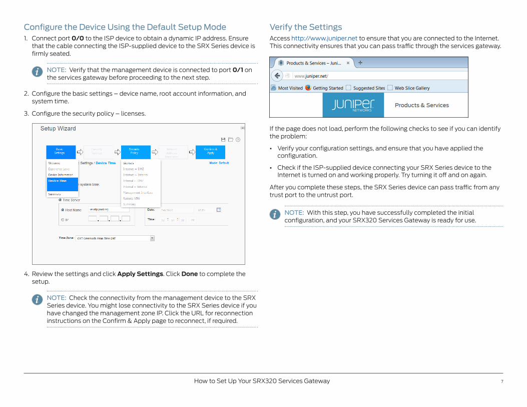
Configure the Device Using the Default Setup Mode1. Connect port 0/0 to the ISP device to obtain a dynamic IP address. Ensure
that the cable connecting the ISP-supplied device to the SRX Series device is firmly seated.
NOTE: Verify that the management device is connected to port 0/1 on the services gateway before proceeding to the next step.
2. Configure the basic settings – device name, root account information, and system time.
3. Configure the security policy – licenses.
4. Review the settings and click Apply Settings. Click Done to complete the setup.
NOTE: Check the connectivity from the management device to the SRX Series device. You might lose connectivity to the SRX Series device if you have changed the management zone IP. Click the URL for reconnection instructions on the Confirm & Apply page to reconnect, if required.
Verify the SettingsAccess http://www.juniper.net to ensure that you are connected to the Internet. This connectivity ensures that you can pass traffic through the services gateway.
If the page does not load, perform the following checks to see if you can identify the problem:
• Verify your configuration settings, and ensure that you have applied the con figuration.
• Check if the ISP-supplied device connecting your SRX Series device to the Internet is turned on and working properly. Try turning it off and on again.
After you complete these steps, the SRX Series device can pass traffic from any trust port to the untrust port.
NOTE: With this step, you have successfully completed the initial configuration, and your SRX320 Services Gateway is ready for use.

Copyright © 2016, Juniper Networks, Inc. All rights reserved. Juniper Networks, Junos, Steel-Belted Radius, NetScreen, and ScreenOS are registered trademarks of Juniper Networks, Inc. in the United States and other countries. The Juniper Networks Logo, the Junos logo, and JunosE are trademarks of Juniper Networks, Inc. All other trademarks, service marks, registered trademarks, or registered service marks are the property of their respective owners. Juniper Networks assumes no responsibility for any inaccuracies in this document. Juniper Networks reserves the right to change, modify, transfer, or otherwise revise this publication without notice. Part Number: 530-066669 Rev. 01, March 2016.
Change the Configuration Settings (Optional)After you complete the initial setup configuration, you can access the J-Web setup wizard by clicking Configuration Wizards > Set Up. You can either edit the existing settings or create a new configuration. If you choose to create a new configuration, then all the current configuration in the services gateway will be deleted.
Power Off the DeviceYou can power off the device in one of the following ways:
• Graceful shutdown—Press and immediately release the Power button.
• Forced shutdown—Press the Power button, and hold it for 10 seconds.
After powering off a power supply, wait at least 60 seconds before turning it back on.
Reset the ConfigurationUse the RESET CONFIG button to restore the device to the factory-default configuration or to a rescue configuration. To press the RESET CONFIG button, insert a small probe (such as a straightened paper clip) into the pinhole on the front panel.
Pressing and quickly releasing the RESET CONFIG button loads and commits the rescue configuration. The rescue configuration is a previously committed, valid configuration set through J-Web or the CLI. The STATUS LED is solid amber during this time.
Pressing and holding the RESET CONFIG button for 15 seconds or more, until the STATUS LED is solid amber, deletes all configurations (backup configurations and rescue configuration), and loads and commits the factory configuration.
NOTE: After a rescue configuration has been set, an amber ALARM LED indicates a minor issue, and a solid red ALARM LED indicates a major problem.
ReferenceJunos OS Documentation http://www.juniper.net/techpubs/en_US/release-independent/junos/information-products/pathway-pages/srx-series/product/index.html
Technical Support http://www.juniper.net/support/requesting-support.html
SRX320 Services Gateway Hardware Guide http://www.juniper.net/techpubs/en_US/release-independent/junos/information-products/pathway-pages/srx-series/product/index.html