How-to Note: Configuring VTO/VTH Devices · To access the Unlock, Audio, Mic options, simply slide...
21
How-to Note: Configuring VTO/VTH Devices [ 13-Jul-16] How to Pair VTO/VTH Devices [VTH/VTO INTERCOM DEVICES] Step 1: You will begin by un-boxing the VTO (wall camera) and the VTH (in-house intercom). We will configure the VTO device first. Step 2: Power the VTO unit with a 12vDC 1AMP source and connect it to your desired network switch/router. The default IP address of the VTO device is ‘10.22.5.189’. Step 3: If you need to change the addressing of the VTO device or if you have multiple VTO devices that will be installed, access the unit’s web interface by typing the default address in Internet Explorer (i.e. http://10.22.5.189). You will be presented with a login screen. Default is ‘ admin’ and ‘admin’. Click on ‘Network Config’ and you will see the option to change all needed parameters for the VTO device. Note: If you cannot access the device on its default IP address, you will need to set your PC to a local address that is in the same IP scheme as the VTO such as ‘10.22.5.100’. Step 4: While in the VTO's web interface, we have to add the VTH devices it will be speaking to. Click on 'Indoor Station Manager' under the 'System Config' section. Click on the 'Add' button. Input the first and last name of the residence you are installing at and finally input the addresses of the VTH devices you will be working with. Now issue it a Room No. (you can leave it default to 101). This number will be used to sync the IP cameras and monitors together so they know how to communicate.
Transcript of How-to Note: Configuring VTO/VTH Devices · To access the Unlock, Audio, Mic options, simply slide...

How-to Note: Configuring VTO/VTH Devices [ 13-Jul-16]
How to Pair VTO/VTH Devices [VTH/VTO INTERCOM DEVICES]
Step 1: You will begin by un-boxing the VTO (wall camera) and the VTH (in-house intercom). We will configure the VTO device first.
Step 2: Power the VTO unit with a 12vDC 1AMP source and connect it to your desired network switch/router. The default IP address of the VTO device is ‘10.22.5.189’.
Step 3: If you need to change the addressing of the VTO device or if you have multiple VTO devices that will be installed, access the unit’s web interface by typing the default address in Internet Explorer (i.e. http://10.22.5.189). You will be presented with a login screen. Default is ‘admin’ and ‘admin’. Click on ‘Network Config’ and you will see the option to change all needed parameters for the VTO device.
Note: If you cannot access the device on its default IP address, you will need to set your PC to a local address that is in the same IP scheme as the VTO such as ‘10.22.5.100’.
Step 4: While in the VTO's web interface, we have to add the VTH devices it will be speaking to. Click on 'Indoor Station Manager' under the 'System Config' section. Click on the 'Add' button. Input the first and last name of the residence you are installing at and finally input the addresses of the VTH devices you will be working with. Now issue it a Room No. (you can leave it default to 101). This number will be used to sync the IP cameras and monitors together so they know how to communicate.

Note: The default IP for all VTH devices is '10.22.5.180'
Step 5: Now that we have our VTO device(s) addressed and able to access on the network, we need to pair it with the main VTH (in-house intercom) device. Proceed by powering the unit with a 12vDC 1AMP source and connect the device to your network. The default IP address of the VTH device is ’10.22.5.180’. To change the IP address of the VTH unit, tap on ‘Settings’ -> ‘Project Settings’. It will prompt for password which by default is ‘002236’. Now tap on Net Set which brings you to the unit's network properties. Change it to the desired address that will fit with the network you are applying this to. Now tap Product Info. Keep the option on 'Master' (unless you are using Group Calling) and input the Room No. you input on the VTO from the previous step.

Step 6: While still in the ‘Project Setting’ menu, tap on ‘Network’. This is where you will pair the VTO device(s) that are already setup on the network from the previous steps. Tap in the IP address of VTO device you want to add to the intercom system. Make sure ‘Enable’ is set to 'ON' at the bottom. You are able to add up to 8 VTO devices per VTH system. Simply tap the arrow symbol that is pointing to the right to add additional VTO devices.

Step 7: You should now have at least one VTO device that we can test with to communicate to your main VTH device. Press your finger on the circular indicator on the VTO to send a call to the VTH it’s paired to. If successful, you should hear the VTH ring and present live video/audio from the VTO!
Note: If you are presented with an error that it cannot call out, recycle the power on all devices involved to assured all settings took hold.
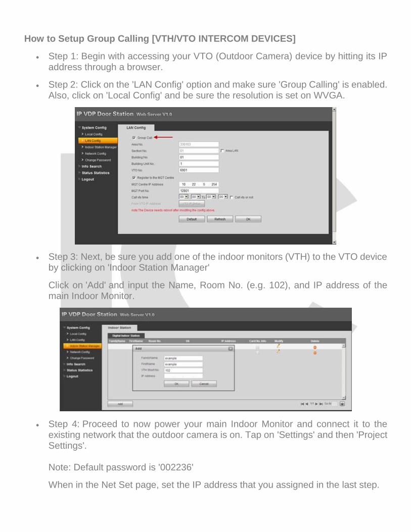
How to Setup Group Calling [VTH/VTO INTERCOM DEVICES]
Step 1: Begin with accessing your VTO (Outdoor Camera) device by hitting its IP address through a browser.
Step 2: Click on the 'LAN Config' option and make sure 'Group Calling' is enabled. Also, click on 'Local Config' and be sure the resolution is set on WVGA.
Step 3: Next, be sure you add one of the indoor monitors (VTH) to the VTO device by clicking on 'Indoor Station Manager'
Click on 'Add' and input the Name, Room No. (e.g. 102), and IP address of the main Indoor Monitor.
Step 4: Proceed to now power your main Indoor Monitor and connect it to the existing network that the outdoor camera is on. Tap on 'Settings' and then 'Project Settings'. Note: Default password is '002236'
When in the Net Set page, set the IP address that you assigned in the last step.

Now tap on Product Info and input the Room No. you applied to the VTO in the previous step.
Step 5: Tap on the 'Network' option next. Add a title to the main VTO (Outdoor Camera) device along with its IP address and enable it at the bottom. If it pairs successfully, you will see that a VTO Middle No. is added.

Step 6: Now power up the rest of the other Indoor Monitors that will be receiving the call from the VTO (Outdoor Camera).
Note: You can add up to 6 total Indoor Monitors to perform Group Calling Get in to 'Settings' , 'Product Info' for the additional Indoor Monitor and tap on 'Master' to turn it to 'Extension'. Use the same Room No. used on the'Master' Indoor Monitor along with a '-1' at the end of it. Address this Indoor Monitor and then add the 'Master' IP address of the first one you did at the bottom. If successful, you do not need to add the network information of the VTO (Outdoor Monitor) device. It should auto synchronize with the 'Master' Monitor and add it to the Group Call.
Note: If you have more than one additional monitor to add, continue to add the 'Master' Room No. along with a - 'number' such as '-2', '-3', etc.
Step 7: If setup correctly, you should now be able to make a call from the Outdoor Camera and ring to all Indoor Monitors that are part of the project.
Note: If some of the Indoor Monitors don't receive a call from the Outdoor Camera when activated, please recycle power to all devices involved.

VTO – How to setup push notifications
How-to: How to enable Push notifications from your VTO to your mobile device and working in conjunction with the ICRSS PRO app.
When video call is made you will receive push notification to your mobile device this will allow you to open the notification and see live video from the VTO and be able to interact with the caller.
Step 1: Log into your router and port forward your VTO. This will enable you to view the video from your VTO remotely. The default TCP port of the VTO is 37777.
Step 2: Make sure you have the latest version of ICRSS PRO (at least 5.20.100).
Note: To verify version: Go to Settings > Help > About.
Step 3: Add the VTO as device in device manager.
Note: Go to Settings
Step 4: Go to
Step 5: Click on the + symbol (add a device)
Step 6: Add your VTO’s network info:
Note: a. Give it a name
b. Enter the public ip or DDNS address.
c. Enter the TCP port#.
d. Enter the username
e. Enter the password

Example:
f. Press the Check VTO icon

Check VTO should now say “VTO Connected”
Step 7: Click on Save icon
Step 8: Go to Settings
Step 9: Select Push Config
If connection is successful, you will get a message.
The Push Config should now be enabled and ready for a live call. Note: To Answer a VTO call When a person rings the VTO doorbell. On your phone you will receive a notification. Usually this is located at the very top of your screen in the notification bar/section.

Select the Live Call notification. It will take you a live video feed from the VTO.
To access the Unlock, Audio, Mic options, simply slide the bar at the bottom sideways. To exit the live call: simply exit the live view window. a. Unlock: unlock feature (optional) to be used with an electronic lock/latch. b. Sound: on/off c. Mic: mic on/off (2way talk - start dialog) If you don’t answer: You can still monitor who is at the door by selecting the event notification or opening the event in Event List.

To check previous calls/events
Step 10: Go to Settings
Step 11: Go to
Step 12: Event List: Any calls from the VTO will be titled/logged as Live Calls. Live call will contain the time/date/channel/device name.
Select an event to see the live video feed from the cam.
Note: Port forwarding: The port forwarding rule for the VTO would be separate/independent from your NVR/DVR’s port forwarding rules. Please make sure the protocol for the TCP port rule is set to TCP only. Menus options might vary between Android and IOS.

VTH – How to add an IC Realtime IP camera "How to add an IPC camera for monitoring only in a VTH. This will not work not to be used with the call functions."
Step 1: "In the Main menu: select Settings"
Step 2: " Under System Settings > Local IPC"
Step 3: Under Local IPC, enter the following info: IPC Name, IP Address, username, password. TCP port 37777 is assumed (cannot change default port). Note: You can add up to 8 IP Cameras (press right arrow selection).
Step 4: Select Save

Step 5: In the Main menu: select Video Talk
Step 6: Select Monitor
Step 7: Select IPC
Step 8: Select your IP camera
Note: You should now be able to see the video.

Note: Press Return to go back to the previous menu. Reminder: This feature is only for monitoring and not part of the video call. Video call only works with the VTO."
How-to: How to increase or decrease the time before the Screensaver turns on.
The Screensaver turns on (screen turns off) by default after 120 seconds of inactivity.
Step 1: In the Main menu: select Settings
Step 2: Under User Settings select Display
Step 3: Change the Screensaver Time
Step 4: Select OK

VTH to VTH audio conference [VTH / VTO] How to talk to another VTH (Indoor monitor)
Step 1: Press the Call Button on the VTH that you are going to me initiating the call from.
Step 2: Select Call User
Step 3: Select the Address book or type the room # and press the green dial icon. In this example, press the Address Book Icon
Step 4: Select the contact/room#

Step 5: Select Call
Step 6: Press the Answer button to answer the call.
VTH calling the main VTH
:

Main VTH being called:
Example of established audio conference
Main VTO
Sub-VTH

You may now speak to the person at the other end. Note: Actual pictures may vary. VTH to VTH is an audio conference only (no video).

Reference Notes: Access Control Module
In utilizing our Access Control Modules (comes with IP cameras that belong to our Intercom System line) to release door strikes, send a trigger to an alarm input and more, please follow the figures below. Note to be sure you are powering the Access Module with a 12v DC 1amp source.

IC Realtime LLC
www.icrealtime.com 3050 N Andrews Avenue Extension | Pompano Beach, FL 33064 | (866) 997-9009
Designs and specifications subject to change without notice. Copyright © 2015 IC Realtime, LLC. All rights reserved.