How to increase allowable bending moment ? Increase truss dimensions = most effective
41
How to increase allowable bending moment ? 1. Increase truss dimensions = most effective 2. Increase diameter main chords 3. Increase wall thickness main chord
-
Upload
brynn-landry -
Category
Documents
-
view
34 -
download
3
description
How to increase allowable bending moment ? Increase truss dimensions = most effective Increase diameter main chords Increase wall thickness main chord. Be nding moment caused by Wind force. Loading force. Wind force. Wind loading on a canopy or projection screen. - PowerPoint PPT Presentation
Transcript of How to increase allowable bending moment ? Increase truss dimensions = most effective

How to increase allowable bending moment ?
1. Increase truss dimensions = most effective
2. Increase diameter main chords
3. Increase wall thickness main chord

Bending moment caused by Wind force
Loading force
Wind force

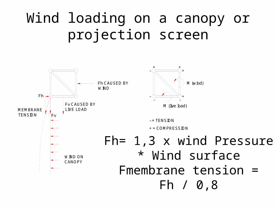
Wind loading on a canopy or projection screen
WIND ON CANOPY
Fv CAUSED BY LIVE LOADMEMBRANE
TENSION Fv
Fh
Fh CAUSED BY WIND
++
+
- -+-
-
- = TENSION
+ = COMPRESSION
M (wind)
M (live load)
Fh= 1,3 x wind Pressure * Wind surface
Fmembrane tension = Fh / 0,8

Beaufort number Wind speed / wind pressure
Land conditions
km/h m/s kN/m^2
0 0 0-0.2 0 Calm. Smoke rises vertically.
1 1-6 0.3-1.5 0,001 Wind motion visible in smoke.
2 7-11 1.6-3.3 0,007 Wind felt on exposed skin. Leaves rustle.
3 12-19 3.4-5.4 0,02 Leaves and smaller twigs in constant motion.
4 20-29 5.5-7.9 0,04 Dust and loose paper raised. Small branches begin to move.
5 30-39 8.0-10.7 0,07 Smaller trees sway.
6 40-50 8.0-10.7 0,12 Large branches in motion. Whistling heard in overhead wires. Umbrella use becomes difficult.
7 51-62 13.9-17.1 0,18 Whole trees in motion. Effort needed to walk against the wind.
8 63-75 17.2-20.7 0,27 Twigs broken from trees. Cars veer on road.
9 76-87 20.8-24.4 0,37 Light structure damage.
10 88-102 24.5-28.4 0,50 Trees uprooted. Considerable structural damage.
11 103-117 28.5-32.6 0,67 Widespread structural damage.
12 >117 >32.7 0,85 Massive and widespread damage to structures.

Transversal force ( Also known as shear force )

Example’s of situations when transversal forces will be determine the maximum loading:
1. A heavy load on a short span.
2. A heavy load near to the suspension point.
3. Truss constructions underneath a stage floor.

How to increase allowable transversal force ?
1. Increase the diameter of the brace
2. Increase the wall thickness of the brace
3. Increase wall thickness of the main chord

NORMAL FORCE

Examples of situations when a normal force occurs:• Towers• Columns• Rafter trusses in a MPT or ST roof

EXTERNALFORCE


How to increase the normal force?
1. Increase tube diameter
2. Increase wall thickness of tubes

TORSION FORCE

Examples of situations when torsion will occur:• Equipment on a boom arm• Equipment which are all positioned on one tube
of a truss

How to increase the normal force?
1. Increase the amount of cross braces inside the truss.
2. Use a bigger truss.

Deflection• The elastic movement of a structure under
load• Deformation by self weight and pay load > the
truss starts to bend/deflect

How to minimise deflection ?
1. Increase truss dimensions = most effective
2. Use stiffer material e.g. steel
3. PRE-camber the truss
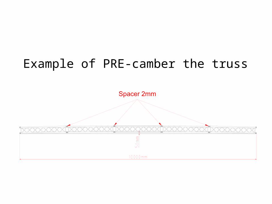
Example of PRE-camber the truss

When is deflection important ?
1. When rigging a fixed LED screen.
2. Personal feeling > a floor which deflects a lot “feels” unsafe

Suspending load from a truss system.
•Heavy loading should always be attached near or to or at the nodepoints
•Small loadings up to 100 Kg can be attached anywhere on the truss.


Possible mistakes of a Truss.
Parallel running braces
Miss nodding


Miss Nodding
Bendingmoment
NO bendingmoment

Analising loading of truss structures.
• The type of structure determines the allowable loading.
• Loading tables are only valid for simply supported spans.
• Other types of constructions or structures have to be calculated in a structural report.

Simply supported span:• Truss on two hoists,• truss on two towers

Continious span:• Truss on three or more hoists,• truss on three or more towers

Span:• Free span is the total length between 2
suspension points
Loading capacity:• The ability of the truss to withstand a load
within its tolerances

Reaction force on suspension points

Situation 1:Spann of 20m loaded with 2000 Kg
UDL ( including selfweight of the truss.)
The spann is suspended on 2 chainhoist.
Eache suspention point will be loaded by 1000 Kg, a 1 ton motor can be
used.

Situation 2:Spann of 20m loaded with 2000 Kg
UDL ( including selfweight of the truss.)
the spann is suspended on 3 chainhoist.
The 2 outer suspension poins will be loaded with 380 Kg, and the middle suspention point will be loaded with
1240 Kg, the middle motor now needs to be a 2 ton chain hoist.

Know your load:
• Know the suspended loads from your Truss
• Know the reaction forces on the suspension points
• Make upfront a rigging plot of the loading setup

Know your load:
• Know the suspended loads from your Truss
• Know the reaction forces on the suspension points
• Make upfront a rigging plot of the loading setup


Text underneath the loading table

TRUSS STANDARDS
Design standards
• DIN 4113 German standard
• VPLT SR 1.0 German “Code of practice”
• BS 8118 British standard
• BS 7906-1 / BS 7905-2 British standard for design, manufacture and use
• Euro-code 9 European standard (not enforced yet)

TRUSS STANDARDS
Standards for temporary structuresDesign standards
• DIN 4112 German standard
• BS Temporary Demountable structures British “code of practice “
• EN 13814 European standard for temporary demountable structures

TECHNICAL TRAINING
Questions?