![IEEE Std 421.5-1992, IEEE Recommended Practice for Excitation …u.dianyuan.com/bbs/u/38/1139052706.pdf · 2020. 5. 12. · [2] IEEE Std 100-1988, IEEE Standard Dictionary of Electrical](https://static.fdocuments.in/doc/165x107/611c6fe7b258d970e2075190/ieee-std-4215-1992-ieee-recommended-practice-for-excitation-u-2020-5-12.jpg)
IEEE Std 3001.11-2017 IEEE Recommended Practice …...IEEE Std 3001.11 -2017 IEEE Recommended...
91
Recommended Practice for Application of Controllers and Automation to Industrial and Commercial Power Systems IEEE Std 3001.11 ™ -2017 IEEE 3001 STANDARDS: POWER SYSTEMS DESIGN
Transcript of IEEE Std 3001.11-2017 IEEE Recommended Practice …...IEEE Std 3001.11 -2017 IEEE Recommended...

Recommended Practice for Application of Controllers and Automation to Industrial and Commercial Power Systems
IEEE Std 3001.11™-2017
IEEE 3001 STANDARDS: POWER SYSTEMS DESIGN
IEEE Std 3001.11™-2017
IEEE Recommended Practice for Application of Controllers and Automation to Industrial and Commercial Power Systems
Sponsor Technical Books Coordinating Committee of the IEEE Industry Applications Society
Approved 23 March 2017
IEEE-SA Standards Board

Abstract: The selection and application of controllers and automation to industrial and commercial power systems is covered by this recommended practice. It is likely to be of greatest value to the power-oriented engineer with limited experience with this equipment. It can also be an aid to all engineers responsible for the electrical design of industrial and commercial power systems.
Keywords: automation, building automation system (BAS), contactor, controller, facility automation system (FAS), heater controller, IEEE 3001.11™, industrial controller, motor control, motor control center (MCC), motor controller, motor starter, power controller, starter
The Institute of Electrical and Electronics Engineers, Inc.3 Park Avenue, New York, NY 10016-5997, USA
Copyright © 2017 by The Institute of Electrical and Electronics Engineers, Inc. All rights reserved. Published 12 September 2017. Printed in the United States of America.
IEEE is a registered trademark in the U.S. Patent & Trademark Office, owned by The Institute of Electrical and Electronics Engineers, Incorporated.
PDF: ISBN 978-1-5044-3915-2 STD22511Print: ISBN 978-1-5044-3916-9 STDPD22511
IEEE prohibits discrimination, harassment, and bullying.For more information, visit http:// www .ieee .org/ web/ aboutus/ whatis/ policies/ p9 -26 .html.No part of this publication may be reproduced in any form, in an electronic retrieval system or otherwise, without the prior written permission of the publisher.

3Copyright © 2017 IEEE. All rights reserved.
Important Notices and Disclaimers Concerning IEEE Standards Documents
IEEE documents are made available for use subject to important notices and legal disclaimers. These notic-es and disclaimers, or a reference to this page, appear in all standards and may be found under the heading “Important Notices and Disclaimers Concerning IEEE Standards Documents.” They can also be obtained on request from IEEE or viewed at http:// standards .ieee .org/ IPR/ disclaimers .html.
Notice and Disclaimer of Liability Concerning the Use of IEEE Standards Documents
IEEE Standards documents (standards, recommended practices, and guides), both full-use and trial-use, are developed within IEEE Societies and the Standards Coordinating Committees of the IEEE Standards Asso-ciation (“IEEE-SA”) Standards Board. IEEE (“the Institute”) develops its standards through a consensus de-velopment process, approved by the American National Standards Institute (“ANSI”), which brings together volunteers representing varied viewpoints and interests to achieve the final product. IEEE Standards are doc-uments developed through scientific, academic, and industry-based technical working groups. Volunteers in IEEE working groups are not necessarily members of the Institute and participate without compensation from IEEE. While IEEE administers the process and establishes rules to promote fairness in the consensus develop-ment process, IEEE does not independently evaluate, test, or verify the accuracy of any of the information or the soundness of any judgments contained in its standards.
IEEE Standards do not guarantee or ensure safety, security, health, or environmental protection, or ensure against interference with or from other devices or networks. Implementers and users of IEEE Standards doc-uments are responsible for determining and complying with all appropriate safety, security, environmental, health, and interference protection practices and all applicable laws and regulations.
IEEE does not warrant or represent the accuracy or content of the material contained in its standards, and expressly disclaims all warranties (express, implied and statutory) not included in this or any other document relating to the standard, including, but not limited to, the warranties of: merchantability; fitness for a particular purpose; non-infringement; and quality, accuracy, effectiveness, currency, or completeness of material. In addition, IEEE disclaims any and all conditions relating to: results; and workmanlike effort. IEEE standards documents are supplied “AS IS” and “WITH ALL FAULTS.”
Use of an IEEE standard is wholly voluntary. The existence of an IEEE standard does not imply that there are no other ways to produce, test, measure, purchase, market, or provide other goods and services related to the scope of the IEEE standard. Furthermore, the viewpoint expressed at the time a standard is approved and issued is subject to change brought about through developments in the state of the art and comments received from users of the standard.
In publishing and making its standards available, IEEE is not suggesting or rendering professional or other services for, or on behalf of, any person or entity nor is IEEE undertaking to perform any duty owed by any other person or entity to another. Any person utilizing any IEEE Standards document, should rely upon his or her own independent judgment in the exercise of reasonable care in any given circumstances or, as appropri-ate, seek the advice of a competent professional in determining the appropriateness of a given IEEE standard.
IN NO EVENT SHALL IEEE BE LIABLE FOR ANY DIRECT, INDIRECT, INCIDENTAL, SPECIAL, EXEMPLARY, OR CONSEQUENTIAL DAMAGES (INCLUDING, BUT NOT LIMITED TO: PROCURE-MENT OF SUBSTITUTE GOODS OR SERVICES; LOSS OF USE, DATA, OR PROFITS; OR BUSINESS INTERRUPTION) HOWEVER CAUSED AND ON ANY THEORY OF LIABILITY, WHETHER IN CON-TRACT, STRICT LIABILITY, OR TORT (INCLUDING NEGLIGENCE OR OTHERWISE) ARISING IN ANY WAY OUT OF THE PUBLICATION, USE OF, OR RELIANCE UPON ANY STANDARD, EVEN IF ADVISED OF THE POSSIBILITY OF SUCH DAMAGE AND REGARDLESS OF WHETHER SUCH DAMAGE WAS FORESEEABLE.

4Copyright © 2017 IEEE. All rights reserved.
Translations
The IEEE consensus development process involves the review of documents in English only. In the event that an IEEE standard is translated, only the English version published by IEEE should be considered the approved IEEE standard.
Official statements
A statement, written or oral, that is not processed in accordance with the IEEE-SA Standards Board Operations Manual shall not be considered or inferred to be the official position of IEEE or any of its committees and shall not be considered to be, or be relied upon as, a formal position of IEEE. At lectures, symposia, seminars, or educational courses, an individual presenting information on IEEE standards shall make it clear that his or her views should be considered the personal views of that individual rather than the formal position of IEEE.
Comments on standards
Comments for revision of IEEE Standards documents are welcome from any interested party, regardless of membership affiliation with IEEE. However, IEEE does not provide consulting information or advice pertain-ing to IEEE Standards documents. Suggestions for changes in documents should be in the form of a proposed change of text, together with appropriate supporting comments. Since IEEE standards represent a consensus of concerned interests, it is important that any responses to comments and questions also receive the concur-rence of a balance of interests. For this reason, IEEE and the members of its societies and Standards Coordi-nating Committees are not able to provide an instant response to comments or questions except in those cases where the matter has previously been addressed. For the same reason, IEEE does not respond to interpretation requests. Any person who would like to participate in revisions to an IEEE standard is welcome to join the relevant IEEE working group.
Comments on standards should be submitted to the following address:
Secretary, IEEE-SA Standards Board445 Hoes LanePiscataway, NJ 08854 USA
Laws and regulations
Users of IEEE Standards documents should consult all applicable laws and regulations. Compliance with the provisions of any IEEE Standards document does not imply compliance to any applicable regulatory require-ments. Implementers of the standard are responsible for observing or referring to the applicable regulatory requirements. IEEE does not, by the publication of its standards, intend to urge action that is not in compliance with applicable laws, and these documents may not be construed as doing so.
Copyrights
IEEE draft and approved standards are copyrighted by IEEE under US and international copyright laws. They are made available by IEEE and are adopted for a wide variety of both public and private uses. These include both use, by reference, in laws and regulations, and use in private self-regulation, standardization, and the pro-motion of engineering practices and methods. By making these documents available for use and adoption by public authorities and private users, IEEE does not waive any rights in copyright to the documents.

5Copyright © 2017 IEEE. All rights reserved.
Photocopies
Subject to payment of the appropriate fee, IEEE will grant users a limited, non-exclusive license to photocopy portions of any individual standard for company or organizational internal use or individual, non-commercial use only. To arrange for payment of licensing fees, please contact Copyright Clearance Center, Customer Ser-vice, 222 Rosewood Drive, Danvers, MA 01923 USA; +1 978 750 8400. Permission to photocopy portions of any individual standard for educational classroom use can also be obtained through the Copyright Clearance Center.
Updating of IEEE Standards documents
Users of IEEE Standards documents should be aware that these documents may be superseded at any time by the issuance of new editions or may be amended from time to time through the issuance of amendments, corri-genda, or errata. An official IEEE document at any point in time consists of the current edition of the document together with any amendments, corrigenda, or errata then in effect.
Every IEEE standard is subjected to review at least every 10 years. When a document is more than 10 years old and has not undergone a revision process, it is reasonable to conclude that its contents, although still of some value, do not wholly reflect the present state of the art. Users are cautioned to check to determine that they have the latest edition of any IEEE standard.
In order to determine whether a given document is the current edition and whether it has been amended through the issuance of amendments, corrigenda, or errata, visit the IEEE Xplore at http:// ieeexplore .ieee .org/ or contact IEEE at the address listed previously. For more information about the IEEE-SA or IEEE’s standards development process, visit the IEEE-SA Website at http:// standards .ieee .org.
Errata
Errata, if any, for all IEEE standards can be accessed on the IEEE-SA Website at the following URL: http:// standards .ieee .org/ findstds/ errata/ index .html. Users are encouraged to check this URL for errata periodically.
Patents
Attention is called to the possibility that implementation of this standard may require use of subject matter covered by patent rights. By publication of this standard, no position is taken by the IEEE with respect to the existence or validity of any patent rights in connection therewith. If a patent holder or patent applicant has filed a statement of assurance via an Accepted Letter of Assurance, then the statement is listed on the IEEE-SA Website at http:// standards .ieee .org/ about/ sasb/ patcom/ patents .html. Letters of Assurance may indicate whether the Submitter is willing or unwilling to grant licenses under patent rights without compensation or under reasonable rates, with reasonable terms and conditions that are demonstrably free of any unfair discrim-ination to applicants desiring to obtain such licenses.
Essential Patent Claims may exist for which a Letter of Assurance has not been received. The IEEE is not re-sponsible for identifying Essential Patent Claims for which a license may be required, for conducting inquiries into the legal validity or scope of Patents Claims, or determining whether any licensing terms or conditions provided in connection with submission of a Letter of Assurance, if any, or in any licensing agreements are reasonable or non-discriminatory. Users of this standard are expressly advised that determination of the valid-ity of any patent rights, and the risk of infringement of such rights, is entirely their own responsibility. Further information may be obtained from the IEEE Standards Association.

6Copyright © 2017 IEEE. All rights reserved.
Participants
At the time this IEEE recommended practice was completed, the Power Systems Design Working Group had the following membership:
Gary H. Fox, ChairDuane Leschert, Vice Chair
Sajjad HussainDan NeeserDennis NielsenDev Paul
Shervin ShokoohJeremy SmithPeter Sutherland
Steven TownsendBaskar VairamohanMarcelo ValdesJoseph Weber
The following members of the individual balloting committee voted on this recommended practice. Balloters may have voted for approval, disapproval, or abstention.
William AckermanRobert ArnoFrank BascianoRobert BeaversSirak BelaynehBill BrownGustavo BrunelloWilliam ByrdPaul CardinalStephen ConradRatan DasGlenn DavisDavide De LucaNeal DowlingDonald DunnRandall GrovesWerner HoelzlRonald Hotchkiss
Alan JensenSong JinLaszlo KadarChad KennedyYuri KhersonskyJim KulchiskyMarc LacroixJerry MurphyDaniel NeeserDennis NeitzelMichael NewmanJoe NimsLorraine PaddenAntony ParsonsIulian ProfirJames ReillyMichael RobertsCharles Rogers
Bartien SayogoTed SchoenbergRobert SeitzNikunj ShahMichael SimonJeremy SmithJerry SmithGary SmullinWayne StecEugene StoudenmireK. StumpDavid TepenWayne TimmMarcelo ValdesJohn VergisJohn WangKenneth WhiteOren Yuen
When the IEEE-SA Standards Board approved this recommended practice on 23 March 2017, it had the following membership:
Jean-Philippe Faure, ChairVacant Position, Vice ChairJohn D. Kulick, Past Chair
Konstantinos Karachalios, Secretary
Chuck AdamsMasayuki AriyoshiTed BurseStephen DukesDoug EdwardsJ. Travis GriffithGary Hoffman
Michael JanezicThomas KoshyJoseph L. Koepfinger*Kevin LuDaleep MohlaDamir NovoselRonald C. PetersenAnnette D. Reilly
Robby RobsonDorothy StanleyAdrian StephensMehmet UlemaPhil WennblomHoward WolfmanYu Yuan
*Member Emeritus

7Copyright © 2017 IEEE. All rights reserved.
Introduction
This introduction is not part of IEEE Std 3001.11–2017, IEEE Recommended Practice for Application of Controllers and Automation to Industrial and Commercial Power Systems.
IEEE 3000 Standards Collection™
This recommended practice was developed by the Technical Books Coordinating Committee of the Industrial and Commercial Power Systems Department of the Industry Applications Society as part of a project to re-package the popular IEEE Color Books®. The goal of this project is to speed up the revision process, eliminate duplicate material, and facilitate use of modern publishing and distribution technologies.
When this project is completed, the technical material in the 13 IEEE Color Books will be included in a series of new standards—the most significant of which will be a new standard, IEEE Std 3000™, IEEE Rec-ommended Practice for the Engineering of Industrial and Commercial Power Systems. The new standard will cover the fundamentals of planning, design, analysis, construction, installation, startup, operation, and maintenance of electrical systems in industrial and commercial facilities. Approximately 60 additional dot standards, organized into the following categories, will provide in-depth treatment of many of the topics intro-duced by IEEE Std 3000™:
— Power Systems Design (3001 series)
— Power Systems Analysis (3002 series)
— Power Systems Grounding (3003 series)
— Protection and Coordination (3004 series)
— Emergency, Standby Power, and Energy Management Systems (3005 series)
— Power Systems Reliability (3006 series)
— Power Systems Maintenance, Operations, and Safety (3007 series)
In many cases, the material in a dot standard comes from a particular chapter of a particular IEEE Color Book. In other cases, material from several IEEE Color Books has been combined into a new dot standard.
IEEE Std 3001.11
The material in this recommended practice largely comes from subclauses 10.6 and 10.7 of the IEEE Red Book™, IEEE Std 141™-1993, IEEE Recommended Practice for Electric Power Distribution in Industrial Plants, and Chapters 6 and 14 of the IEEE Grey Book™, IEEE Std 241™-1990, IEEE Recommended Practice for Electric Power Systems in Commercial Buildings.
This publication provides a recommended practice for the electrical design of commercial and industrial fa-cilities. It is likely to be of greatest value to the power-oriented engineer with limited commercial or industrial plant experience. It can also be an aid to all engineers responsible for the electrical design of commercial and industrial facilities. However, it is not intended as a replacement for the many excellent engineering texts and handbooks commonly in use, nor is it detailed enough to be a design manual. It should be considered a guide and general reference on electrical design for commercial and industrial facilities.
Tables, charts, and other information that have been extracted from codes, standards, and other technical liter-ature are included in this publication. Their inclusion is for illustrative purposes; where technical accuracy is important, the latest version of the referenced document should be consulted to assure use of complete, up-to-date, and accurate information.

8Copyright © 2017 IEEE. All rights reserved.
Contents
1. Overview ..................................................................................................................................................... 91.1 Scope .................................................................................................................................................... 9
2. Normative references .................................................................................................................................. 9
3. Definitions and acronyms .......................................................................................................................... 103.1 Definitions .......................................................................................................................................... 103.2 Acronyms ........................................................................................................................................... 11
4. Controllers ................................................................................................................................................. 124.1 General discussion .............................................................................................................................. 124.2 Controllers .......................................................................................................................................... 134.3 Motor controllers ................................................................................................................................ 154.4 Full-voltage (across-the-line) non-reversing starters .......................................................................... 204.5 Reduced-voltage controllers ............................................................................................................... 214.6 Wound-rotor motor controllers ........................................................................................................... 274.7 Multispeed motor controllers ............................................................................................................. 274.8 Single-phase motor starting ................................................................................................................ 284.9 Controllers for dc motors .................................................................................................................... 294.10 Adjustable-speed drives (ASDs) ....................................................................................................... 294.11 Controller arrangements ................................................................................................................... 334.12 Loads ................................................................................................................................................ 43
5. Automation ................................................................................................................................................ 495.1 Introduction ........................................................................................................................................ 495.2 Relay-based control systems .............................................................................................................. 495.3 Microprocessor-based controls ........................................................................................................... 505.4 Industrial automation .......................................................................................................................... 505.5 Facility automation system (FAS) ...................................................................................................... 51
Annex A (informative) Bibliography .............................................................................................................. 84

9Copyright © 2017 IEEE. All rights reserved.
1. Overview
1.1 Scope
This recommended practice covers the selection and application of controllers and automation to industrial and commercial power systems. It is likely to be of greatest value to the power-oriented engineer with limited experience with this equipment. It can also be an aid to all engineers responsible for the electrical design of industrial and commercial power systems.
The present edition of this recommended practice focuses on the application of ANSI/NEMA design control-lers. There are differences in the design of IEC controllers which require additional application considerations which are beyond the scope of the present edition.
2. Normative referencesThe following referenced documents are indispensable for the application of this document (i.e., they must be understood and used, so each referenced document is cited in text and its relationship to this document is explained). For dated references, only the edition cited applies. For undated references, the latest edition of the referenced document (including any amendments or corrigenda) applies.
CSA C22.1, Canadian Electrical Code, Part I (CE Code).1
IEEE Std 141™, IEEE Recommended Practice for Electric Power Distribution for Industrial Plants (IEEE Red Book™).2,3
IEEE Std 242™, IEEE Recommended Practice for Protection and Coordination of Industrial and Commercial Power Systems (IEEE Buff Book™).
1The electrical installation code is location specific; consult the version authorized by the relevant authority having jurisdiction (AHJ). CSA standards can be purchased from www .shop .csa .ca.2The IEEE standards or products referred to in this clause are trademarks of The Institute of Electrical and Electronics Engineers, Inc.3IEEE publications are available from The Institute of Electrical and Electronics Engineers, Inc., 445 Hoes Lane, Piscataway, NJ 08854, USA (http:// standards .ieee .org/ ).
IEEE Recommended Practice for Application of Controllers and Automation to Industrial and Commercial Power Systems

IEEE Std 3001.11-2017IEEE Recommended Practice for Application of Controllers and Automation to Industrial and Commercial Power Systems
10Copyright © 2017 IEEE. All rights reserved.
NEMA ICS 2, Industrial Control and Systems Controllers, Contactors, and Overload Relays Rated 600 Volts.4
NEMA ICS 3, Industrial Control and Systems: Medium Voltage Controllers Rated 2001 to 7200 Volts AC.
NFPA 70, National Electrical Code® (NEC®).5,6
3. Definitions and acronyms
3.1 Definitions
For the purposes of this document, the following terms and definitions apply. The IEEE Standards Dictionary Online should be consulted for terms not defined in this clause.7
building automation system (BAS): A system that performs the functions of supervision, control, and moni-toring of a building.
data transmission medium (DTM): The pathway by which signals are transmitted within a facility automa-tion system.
NOTE—Examples include wire, radio transmission, and fiber-optic links. A combination of several types of DTMs may be used, as appropriate, within the facility automation system.8
facility automation system (FAS): A system that performs the functions of supervision, control, and monitor-ing of a facility.
NOTE—One FAS may incorporate many building automation systems (BASs).
field device: Equipment that receives or transmits a signal, such as controllers, sensors, and relays.
field interface device (FID): A mid-level or lower-level data-processing unit that operates compatibly with the central processing unit (CPU), but generally at a different location.
NOTE—These devices are sometimes referred to as satellite processing units (SPUs), remote terminal devices (RTDs), or slave stations.
intelligent multiplexer (IMUX): A device that combines data from a number of points in the data environ-ment and communicates on a single channel.
human/machine interface (HMI): The displays, keyboards, printers, etc., used to allow a human to monitor or modify the operation of a machine, including a system. Syn: man/machine interface (MMI) or operator/machine interface (OMI).
low voltage (LV): Voltages less than 1000 Volts.
NOTE—Refer to 4.2.3 for discussion.
medium voltage (MV): Voltages greater than low voltage, but less than 35 kV.
4NEMA publications are available from the National Electrical Manufacturers Association (http:// www .nema .org/ ).5NFPA publications are published by the National Fire Protection Association (http:// www .nfpa .org/ ).6The electrical installation code is location specific; consult the version authorized by the relevant AHJ.7IEEE Standards Dictionary Online subscription is available at: http:// www .ieee .org/ portal/ innovate/ products/ standard/ standards _dictionary .html.8Notes in text, tables, and figures of a standard are given for information only and do not contain requirements needed to implement this standard.

IEEE Std 3001.11-2017IEEE Recommended Practice for Application of Controllers and Automation to Industrial and Commercial Power Systems
11Copyright © 2017 IEEE. All rights reserved.
NOTE—Refer to 4.2.3 for discussion.
3.2 Acronyms
AHJ authority having jurisdiction
AHU air-handling unit
ASD adjustable-speed drive
ATC automatic temperature control
BAS building automation system
CCTV closed-circuit television
CMMS computerized maintenance management system
CPU central processing unit
DCS distributed control system
DDC direct digital control
DGP data-gathering panel
DTC data terminal cabinet
DTM data transmission medium
EMS energy management system
FAS facility automation system
FID field interface device
HMI human machine interface
HVAC heating, ventilating, and air conditioning
IMUX intelligent multiplexer
LAN local area network
MCC motor control center
MTTR mean time to repair
MUX multiplexer
PID proportional-integral-derivative
PLC programmable logic controller
PWM pulse-width modulation
RTU remote terminal unit (a component of a SCADA system)
SCADA supervisory control and data acquisition
UPS uninterruptible power supply
VDU video display unit
VFD variable frequency drive
IEEE Std 3001.11-2017IEEE Recommended Practice for Application of Controllers and Automation to Industrial and Commercial Power Systems
12Copyright © 2017 IEEE. All rights reserved.
4. Controllers
4.1 General discussion
A controller9, according to the IEEE Standards Dictionary, is “a device or group of devices that serves to gov-ern, in some predetermined manner, the electric power delivered to the apparatus to which it is connected.” This definition is essentially the same as is found in the National Electrical Code® (NEC®) and Canadian Elec-trical Code (CE Code). As such, a controller can be as simple as a manually-operated overload switch mounted on the wall to control a fractional horsepower ventilation fan, or as complex as a variable frequency adjust-able-speed drive in a dedicated building, controlling a medium-voltage motor which drives a large compres-sor. Most industrial loads are motors, so they will be discussed in more detail, but there are other loads in both industrial and commercial facilities which require controllers as well. Electrical heaters are applied for process heating, space heating, and pipe or vessel heating; controllers are required for all of these loads. Lighting is of-ten provided with controllers. Capacitor banks installed for power factor improvement or some other purposes utilize controllers. Other more-specialized loads have specialized controllers associated with them as well. The selection of a controller needs to be based on the electrical and mechanical characteristics of the loads to be controlled. Loads are discussed briefly in 4.11. The majority of motors utilized by industrial facilities are in-tegral horsepower induction motors of squirrel-cage design supplied from distribution systems of three-phase 600 V ac and below. The choice of an integral horsepower motor controller depends on a number of factors:
a) Power source. Does it use dc or ac? Is it single-phase or three-phase? What is the voltage and frequen-cy? Will the system permit large inrush currents during full voltage starting without excessive voltage drop?
b) Motor. Is the controller to be used with dc, squirrel-cage induction, wound-rotor induction, synchro-nous motor, or adjustable frequency drives? What is the horsepower? Will the motor be jogged or re-versed frequently? What is the acceleration time from start to full speed? Will the motor design specify reduced current inrush?
c) Driven load. Is the load geared, belt-driven, or direct-coupled? Loaded or unloaded start? Is it either necessary or desirable to vary the speed of the load?
d) Operation. Is operation to be manual or automatic? What control interfaces are required?
e) Protection. Motor protection is very generally considered to have two separate components: short-cir-cuit and overload protection. Are fuses or circuit protectors to be used for short-circuit protection? To size the elements of motor overload relays, the full-load current of the motor, the ambient temperature at the motor and controller, and the service factor of the motor should be known.
f) Environment. Will either the motor or the controller be subjected to excessive vibration, dirt, dust, oil, or water? Will either be located in a hazardous or corrosive area? What type of enclosure is required?
g) Cable connections and space. Will there be the required space for cable entrance, bending radius, terminations, and for reliable connections to line and load buses? Will capacitors be installed at either the motor terminal box or the controller for power factor improvement10? Will surge-protective equip-ment, surge arresters, and capacitors be installed at the motor terminal box? Will current transformers for motor differential protection be installed at the motor terminal box?
To answer these questions for the proper application of motor controllers, the specifying engineer should seek the assistance of the application engineers from the power supply utility and the manufacturers. In addition, process engineers and operating personnel associated with the installation should be consulted. The proper
9The term controller is also used in process control applications as “a device that operates automatically to regulate a controlled variable in response to a command and a feedback signal.” (IEEE Standards Dictionary). While in a very general manner this device is often included in automation (Clause 5), it is not the focus of IEEE Std 3001.11.10KVAR ratings of power factor improvement capacitors, located either on individual motors or in banks should be selected with care to avoid the possibility of overvoltages caused by motor self-excitation. Refer to IEEE Std 141, Chapter 8, for more information.

IEEE Std 3001.11-2017IEEE Recommended Practice for Application of Controllers and Automation to Industrial and Commercial Power Systems
13Copyright © 2017 IEEE. All rights reserved.
application of a controller to a load requires consideration of the load, the controller, and the power system the controller is connected to.
4.2 Controllers
4.2.1 General
Controllers in general are usually, but not always, specially designed for the load to be controlled. Manu-ally-operated motor controllers are essentially a manual switch of some form, with an integrated overload component.11 All other motor controllers are electrically operated. Motor controllers which do not require adjustable speed operation generally utilize contactors for the control element, unless they are so large that contactors are not available, in which case general purpose circuit breakers are used. Contactors are electro-mechanical switching devices that are available in electrically-held and mechanically-held models. Electri-cally-held models are the most commonly applied; mechanically-held models are preferred for applications where the dropout of the contactor upon loss of supply voltage is disadvantageous. Contactors have much higher mechanical endurance ratings than other types of switching devices, with some published ratings stated in millions of operations.
Fixed-speed motor controllers are available in a wide variety of configurations, depending on voltage, mo-tor-starting considerations, and motor winding details. The common configurations are discussed below. Fixed-speed motor controllers12 are often called motor starters. Controllers for non-motor loads are also avail-able. Any application of a controller to a load requires consideration of the characteristics of that load. Some comments are made under the discussion of load characteristics in 4.11.
Power can be provided to a mechanical load at adjustable speed by electrical or mechanical means. Electrical adjustable-speed drives are available in a wide variety of ratings and configurations which appear to be contin-uously increasing. In some situations, a mechanical adjustable speed mechanism will be utilized in the form of a fluid coupling or a hydraulic pump/hydraulic motor combination.
4.2.2 Disconnects
A controller requires a means of isolation from the power-distribution system for the purpose of servicing and maintaining the controller more safely. Almost any switching device can be used as a disconnect. It is common to combine the function of short-circuit protection into the disconnect device through the use of instanta-neous-trip circuit breakers or fusible switches. In facilities where the NEC applies, the disconnecting means for a motor branch circuit must comply with Article 430, Part IX. Disconnects are generally marked with con-tinuous current ratings, but may also be marked with a horsepower rating.
Besides providing isolation at the controller, additional disconnects may be required local to the load to pro-vide a disconnecting means for the load that can be more closely monitored by the servicing personnel should the load be located out of sight of its controller. These requirements are specified in the NEC and CE Code.
4.2.3 Voltage considerations
While most applications will involve controllers at the same nominal voltage as the connected load, there are situations where a controller will be provided at a different voltage from the load, with a suitable voltage transformation means provided between the two. While this transformation is usually in the form of a power transformer, this may in some applications be accomplished with a solid-state drive.
11Some special motor designs, typically very small fractional horsepower motors, do not require external overload protection.12Discrete multiple-speed motor controllers, such as two-speed controllers, are typically also included in the term motor starters in common usage in North America.

IEEE Std 3001.11-2017IEEE Recommended Practice for Application of Controllers and Automation to Industrial and Commercial Power Systems
14Copyright © 2017 IEEE. All rights reserved.
In general, controllers are classified in accordance with the installation code (NEC or CE Code) designations of low voltage or high voltage. Low voltage in these codes is defined as anything less than 1000 V13, and high voltage as anything higher than low voltage. In most industrial and commercial facilities, the voltage level above 1000 V is informally called medium voltage to distinguish from the common power transmission sys-tem voltages and the outdoor pole- or structure-mounted equipment commonly employed at those voltages. This standard applies the term medium voltage to voltages between 1 kV and 35 kV. Note that some standards, for example the IEEE C37 breaker standards, include this definition of medium voltage under the term high voltage, in compliance with the installation code usage. ANSI C84.1 defines medium voltage as greater than 1000 V and less than 100 kV; some IEEE standards (including IEEE Std 141™) follow this practice. However, there is a tendency in some newer IEEE standards to adopt either 34.5 kV or 35 kV as the upper limit of medi-um voltage. There is presently no consensus in a definition of medium voltage, as noted in the IEEE Standards Dictionary.
4.2.4 Medium-voltage controllers
Controllers are routinely available for system voltages from 1500 V ac to 7200 V ac. At present, there is a limited availability of 13.8 kV controllers; work is progressing on extending the certification standard to in-clude 15 kV rated controllers. There is a tri-national certification listing standard (CSA C22.2 No. 253 [B15], NMX-J-564/106-ANCE [B86], UL 347 [B92]) for this equipment, which supersedes NEMA ICS 3 which was previously the key reference standard.
Two types of controllers are generally available:
a) Class E1 controllers utilize the main contactor to make and break currents up to the rated breaking capacity of the controller. In contrast to Class E2 controllers, the fault interrupting capacity of a Class E1 controller depends on the capacity of the main contactor, which is much smaller than a power fuse.
b) Class E2 controllers utilize the main contactor to make and break operating currents, and utilize medi-um-voltage fuses to interrupt fault currents which exceed the breaking capacity of the main contactor. E2 controllers provide an interrupting fault capacity of 40 kA or 50 kA rms symmetrical, depending on the power fuse used.
A medium-voltage contactor is designed differently from a medium-voltage circuit breaker. The circuit break-er is designed to interrupt a rated (high) fault current, but is not expected to do it thousands of times in its life, while a contactor is designed to interrupt a much lower operating current, but it is expected to do this for many thousands of operations. In applying medium-voltage contactors, it is important to coordinate the protection relay settings with the fuse characteristics and the contactor rated interrupting current. Some situations where this may be a consideration are motor overcurrent (50/51), motor differential current (87M), and ground fault (50/51G) elements.
Additionally, while all the vacuum interrupters (which predominate in new installations) exhibit a current chopping phenomena, the vacuum contactor is designed to have a low chopping current while, due to the more severe fault interrupting duty, a vacuum circuit breaker will have a higher chopping current. This chopping current is important in determining what additional surge protection may be required for controlled motors. For motors too large for any available contactor, where circuit breakers need to be employed, this becomes an important application consideration. For additional information regarding the application of circuit breakers in industrial and commercial applications, refer to IEEE Std 3001.5™ [B38].
Starters for medium-voltage motors are designed as integrated complete units based on maximum horsepower ratings for use with squirrel-cage, wound-rotor, synchronous, and multispeed motors for full- or reduced-volt-age starting. Class E2 controllers are normally used. Each starter will be completely self-contained and pre-wired by the vendor, with all components in place. Contactors will be current rated based on motor horse-
13Some certification standards commonly used for low-voltage controllers are limited to 600 V ac and 1000 V dc. The installation codes variously define low voltage as below 750 V ac to 1500 V ac.
IEEE Std 3001.11-2017IEEE Recommended Practice for Application of Controllers and Automation to Industrial and Commercial Power Systems
15Copyright © 2017 IEEE. All rights reserved.
power requirements. Combinations of motor starters and switchgear are available as assemblies. Starters are available with air-break contactors or vacuum contactors; vacuum contactors predominate in current vendor offerings. While most medium-voltage motor controllers are “across-the-line” types, other starting schemes are available. While the general information on motor-starting schemes in this standard is based on low-volt-age designs and standards, it is adaptable to medium-voltage systems when required.
4.2.5 Low-voltage controllers
NEMA ICS 2 summarizes the NEMA standard for low-voltage magnetic controllers. The related certifica-tion standard is a tri-national standard (CSA C22.2.No. 254 [B16], NMX-J-353-ANCE-2006 [B85], UL 845 [B93]).
In low-voltage ac motor starters, contactors are generally used for controlling the circuit to the motor. Contac-tors should be carefully applied on circuits and in combination with associated short-circuit protective devices (circuit breakers, motor circuit protectors, or fusible disconnects) that will limit the available fault current and the let-through energy to a level the contactor can withstand. These withstand ratings should be in accordance with the certification standards.
Unlike medium-voltage controllers where vacuum interrupters predominate, most low-voltage controllers employ air-break contactors. Some vacuum contactors are available, and are sometimes used for higher power rated controllers, often due to the large physical size of the higher current rated air-break contactors.
A variety of specialty controllers is available for low-voltage non-motor loads.
4.3 Motor controllers
4.3.1 Introduction
The primary function of a motor controller is starting, stopping, and protecting the motor that it serves. In some applications, motor controllers are additionally required to control the speed of the motor, or to facilitate rapid stopping (braking) of the motor. The type of controller used depends upon the motor size and type, the distribution system, any limitations imposed by the local power source, and the desired control functions or operations.
In a typical three-phase ac motor controller, a magnetically-operated contactor connects the motor to the pow-er source. This contactor is designed for a large number of repetitive operations in contrast with the typical circuit breaker. Energizing the contactor’s operating coil with a small amount of control power causes it to close its contacts, connecting each line of the motor to the power supply. If the starter is to be reversing, two contactors, one forward and one reverse, are used to connect the motor with the necessary phase relation for the desired shaft rotation.
4.3.2 Physical protection
The controllers themselves are protected from physical damage, as opposed to electrical damage, by the con-troller enclosure. NEMA standards ICS 6 [B69] and 250 [B62] cover the classification of enclosures and their associated degree of protection. For example, a NEMA 1 (general purpose indoor) enclosure would be used in dry indoor locations. A NEMA 3R (rainproof and sleet-resistant) or 4 X (watertight, dust-tight, and corrosion resistant) enclosures is typically used outdoors. Sprinkler-resistant enclosures are available for installation in areas serviced by fire-suppression sprinklers. Special enclosures are listed for installation in hazardous loca-tions as defined by NEC sections 500 and 505 or CE Code sections 18, 20, J18, or J20.
4.3.3 Overload protection
An overload is an operating condition where the full-load ratings or ampacities of a motor are exceeded. It is not a short-circuit or fault current condition. A running overload is an overcurrent greater than the rated maxi-

IEEE Std 3001.11-2017IEEE Recommended Practice for Application of Controllers and Automation to Industrial and Commercial Power Systems
16Copyright © 2017 IEEE. All rights reserved.
mum running current, but no greater than the locked-rotor current, which is commonly 6.5 times the full-load motor current14. If the situation continues for too long a time period, damage due to overheating can result. Motor life can be shortened due to heating. Overloads cause a rise in the temperature in the motor windings due to the higher than normal current. This increased temperature causes damage and deterioration to the winding insulation.
Motors are required to be protected against overloads by the NEC and CE Code. NEC Article 43015, Part III gives the requirements for motor and branch circuit overload protection for motors of less than 600 V. The various requirements for overload protection are based upon motor duty, horsepower, and type. NEC Ta-ble 430.37 gives the number and location of overloads required for various types of motor and supply system combinations. Under certain conditions, the motor overloads are permitted to be shunted during motor start-ing; see NEC section 430.35.
Motor overload protection is typically provided by overload relays. Overload relays can be thermal, magnetic, or solid-state type, and have inverse time-overcurrent tripping characteristics to allow for starting inrush cur-rent or momentary overloads. This means that for small overcurrents, a longer time will elapse before tripping occurs. At high overcurrents (locked-rotor current) tripping occurs in a shorter time period.
In the case of magnetic relays a dashpot is used to provide the time delay. For thermal relays, the time-current characteristic is derived from the response of components of the relay to heat generated by a thermal element that simulates the heating of the motor windings due to line current. Thermal overloads can be either melting alloy (eutectic) or bimetallic type. Some old installations rely on fuses for overload as well as short-circuit protection; the fuse used in such applications needs to be examined very carefully to confirm it will interrupt reliably on overload conditions. Many motor fuses, such as the medium-voltage “R” rated fuses used in many modern medium-voltage motor starters, are ONLY suitable for short-circuit protection and are NOT suitable for overload protection.
Solid-state overload relays sense motor currents, transform them into logic level signals, and process these signals to simulate motor thermal (I2t) models. Solid-state relays approximate the motor damage curve more closely than either the thermal or magnetic types. Some of these relays offer field selectability for overload class (or curve), and communication capabilities for centralized control or monitoring. Solid-state overload relays permit field adjustment of overload settings, thereby eliminating the need for individual heater elements calibrated to specific motor currents. Some overload relays provide for stator winding overtemperature pro-tection based on embedded detectors, which typically are thermistors for low-voltage motors and RTDs for medium-voltage motors.
Solid-state overload relays for medium-voltage motors are available with many standard and optional mo-tor-protective functions in a singular modular unit, which permit precise protection of motors and allow mo-tors to be utilized very close to their ratings. Protective functions generally available in these electronic relays are inverse time overload protection, instantaneous overcurrent protection, stator winding overtemperature protection based on resistance temperature detectors (RTDs) embedded in stator windings, motor bearing overtemperature protection based on RTDs placed at motor bearings, load bearing over-temperature protec-tion based on RTDs at load bearings, undercurrent protection, underload protection, phase reversal protection, and incomplete sequence protection. Some modern electronic relays provide many more sophisticated protec-tion and monitoring features as well, plus programmable control logic capabilities.
The rating or setting of these units is determined by the full-load motor current and the motor controller used. Relays need to be reset after operation or “tripping.” This can be done manually through a reset button on the controller, or it can be done automatically. Automatic resetting is not permitted where restarting the motor
14Some standards still refer to locked-rotor current as 6.0 times full-load current, but this ratio increases in most modern high-efficiency motors. A compromise position adopted by many industrial users is to limit new motors to a locked-rotor ratio of 6.5 in specifying new motors. If this is not done, the default offering, especially in small integral horsepower NEMA design motors, will generally have a locked-rotor ratio substantially in excess of 6.5, which should be considered when applying controllers to those motors.15The equivalent CE Code material is in section 28.
IEEE Std 3001.11-2017IEEE Recommended Practice for Application of Controllers and Automation to Industrial and Commercial Power Systems
17Copyright © 2017 IEEE. All rights reserved.
would place the operator or other personnel in danger. Ambient temperature compensated and noncompensat-ed overload relays are also available. There are basically two types of applications for ambient compensated relays. The first is where the ambient compensation mechanism is utilized to provide for appropriate trip char-acteristics over a wide range of ambient temperature. These are intended for general use. The other application is where the controller is in a controlled environment, and the motor is in a non-controlled environment (for example, submersible pumps). In applications where the motor and controller are in the same environment, it is not advisable to use ambient compensated overload relays because the protected device (motor, cable) is not ambient compensated.
A motor damage curve shows how long a particular overcurrent can be sustained before the motor is damaged. Devices are available that react to motor overload, phase loss, phase reversal, mechanical jam, ground fault, current unbalance, voltage unbalance, low-voltage conditions, and more. The response time can be changed to fit the application. Solid-state devices can be combined with motor temperature sensors, such as thermistors (typically LV motors) or RTDs (typically MV motors). Memory can be provided if motor starts or overloads happen frequently.
NEMA standards divide overload relays into three classes: Class 10, 20, and 30. Some electronic controllers incorporate all three classes, and sometimes additional interpolations of these classes, in one device. Each class is defined by the maximum time in seconds in which the relay should function on six times its ultimate trip current (1.25 times full-load motor current for motors having a service factor of 1.15; and 1.15 times full-load motor current for motors having a service factor of 1.0). No minimum trip time is standard. Overload re-lays should have sufficient thermal capacity to allow the motor to start. The type of overload relays to be used on a particular application depends upon required reliability, type of load, ambient conditions, motor type and size, safety factors, acceleration time, and probability of an overload.
4.3.4 Overcurrent protection
Overcurrent protection is required to protect motors, and their branch circuits and controllers, from short circuits or ground faults. Overcurrent conditions due to faults can cause damage to motors, controllers, and conductors. NEC Article 430, Part III covers the requirements for overcurrent protection for motors under 600 V. While the overcurrent protection of a controller protects both the conductors and the load, protection of the conductor is not part of the scope of this standard. Refer to IEEE Std 242™, Chapter 9.
Overcurrent protection can be provided by circuit breakers, motor circuit protectors, or fuses. Traditional low-voltage molded case circuit breakers are referred to as thermal-magnetic circuit breakers; they have both a thermal tripping element and a magnetic tripping element. The thermal element provides an inverse time-cur-rent characteristic while the magnetic element provides instantaneous tripping. Motor circuit protectors are typically adjustable instantaneous-trip circuit breakers that have a magnetic element only. Fuses have an inter-nal element that melts under overcurrent conditions. By varying the type of internal construction and materi-als, fuses can be either fast-acting or time-delay types. Time-delay fuses provide both short-circuit and backup overload protection for the motor, if they are sized correctly. Time-delay fuses are typically a dual element type of fuse, but some manufacturers utilize other fuse construction types. Special purpose motor fuses (preva-lent for medium-voltage motor starters) are designed for good short-circuit interrupting characteristics, but are not designed for motor overload protection16. Fuses have to be replaced after operation while circuit breakers only need to be reset, provided they operated on an overload condition. If a circuit breaker operates under a short-circuit condition, which is typical when used for motor branch circuit, short-circuit, and ground fault protection, the fault condition should first be repaired before resetting the circuit breaker. If the fault was near the interrupting capability of the circuit breaker, the circuit breaker should be inspected, tested, and replaced if needed. The devices used to provide the overcurrent protection require a time-current characteristic that is
16Some fuses explicitly caution that they may fail at currents greater than their rated operating current but less than a specified higher current. If there is no specific guidance from the fuse manufacturer, but the provided fuse time-current curve does not extend into the long time region, (often as low as 100 s), it is prudent to assume that the fuse operation in the motor running overload region is either unpredictable or undefined and should be avoided.

IEEE Std 3001.11-2017IEEE Recommended Practice for Application of Controllers and Automation to Industrial and Commercial Power Systems
18Copyright © 2017 IEEE. All rights reserved.
capable of carrying the motor’s starting current, and of operating under fault conditions. NEC Table 430.52 gives the maximum allowable ratings for various types of motor short-circuit protective devices.
When circuit breakers are used to provide motor overcurrent protection, there are two key considerations: the motor locked-rotor current, and the motor inrush current, which exceeds locked-rotor current for a very short time but can cause some circuit breakers to trip. IEEE Std 242 and NEMA MG-1 [B76] indicate that this inrush current is some cases can be as high as 2.83 times locked-rotor current, although 1.76 times locked-rotor cur-rent is traditionally used for industrial designs. Refer to IEEE Std 242, IEEE Std 3004.8™ [B39], and NEMA MG-1 for additional information.
Another consideration in low-voltage motor protection is that of Type 1 versus Type 2 protection. These are two levels of protection that are defined by the International Electrotechnical Commission (IEC). They pertain to the amount of damage the controller is allowed to sustain due to a fault. Under both Types 1 and 2, there is to be no significant damage to the equipment. In Type 1 protection the controller may be damaged to the point that components, or the entire controller, need to be replaced. Under Type 2 protection, only minimal damage to the contactor and controller, in the form of light contact welding, is allowed. The controller is to be opera-tional after fuse replacement and contact separation. No parts are allowed to be replaced except the fuses. Type 2 protection is used where minimal downtime of a process or operation is required after a fault. Type 2 protec-tion can be achieved with both NEMA and IEC products.
Overload and overcurrent protection requirements for motors over 600 V are covered in NEC Article 430, Part XI17. For fire pumps, some of the requirements of NEC 430 are modified. NEC Article 695 and NFPA 20 [B81] cover fire pumps. NEC Article 440 has requirements that are specific to hermetic type motors for air condition-ing and refrigeration equipment. These requirements are in addition to, or modify some of, the requirements in NEC Article 430.
4.3.5 Equipment protection (single phase, undervoltage, and other)
Motors may also need to be protected from adverse conditions other than overloads and overcurrents. Some of these conditions are under/overvoltages, phase reversal, and phase loss. Relays or other devices are available to provide this protection and can be added to the motor controller.
Small voltage unbalances can cause very high currents in the rotor circuit. The condition is even more severe if a three-phase motor runs on a single-phase supply (loss of one phase). Full-load speed reduces slightly when operated at unbalanced voltages. Additionally, locked-rotor and breakdown torques decrease when the voltage is unbalanced. Line monitoring relays sense and react to voltages that are higher or lower than the motor’s normal operating range, but voltage magnitude monitoring does not generally detect a loss of phase on a running motor circuit. Undervoltage can result in overheating and reduced torque. A current imbalance can also result in nuisance tripping of the overloads or circuit protective device. Refer to NEMA MG-1 [B76], IEEE Std 3004.8 [B39], and IEEE Std 242 for additional information.
When a three-phase motor is started from a de-energized state with voltage on only two of the three phases, the motor should not be expected to turn, although current will flow in the windings that is substantially higher than rated motor full-load current. This creates more heat than a stalled motor is designed to dissipate. Where this event is a significant risk, protection should be provided unless replacement of a failed motor is deemed an acceptable mitigation approach. This could be especially dangerous for elevators, where motor replacement is neither trivial nor inexpensive. Suitable phase failure relays and single-phase protection can be provided to protect the motor in these situations.
When motors are transferred from one source to another, for example, from an emergency generator to the util-ity, both the motor controller and the motor are often momentarily de-energized. If the utility voltage is out of phase with the motor residual voltage when the motor is reconnected to the utility source, the motor will often
17Refer to CE Code section 28. CE Code section 36 provides additional “high voltage” rules, but none are specific to motors.

IEEE Std 3001.11-2017IEEE Recommended Practice for Application of Controllers and Automation to Industrial and Commercial Power Systems
19Copyright © 2017 IEEE. All rights reserved.
draw excessive current and generate high-transient torques that may cause nuisance tripping of breakers and possibly cause damage to the motor, portions of the power-distribution system, the driven equipment, the cou-pling to the driven equipment, or the foundation. To overcome this problem, automatic transfer switches often include optional in-phase monitors that prevent transfer until the residual voltage of the motor and the utility voltage are nearly synchronized, or alternately delay transfer until the residual voltage has decayed to a safer level. Phase reversal protection can be added to prevent the motor from operating if the phases are reversed. For applicability to medium-voltage motors, refer to the IEEE PSRC working group J9 report to the Rotating Machinery Protection Subcommittee [B43]. This report contains an extensive bibliography, in addition to pro-viding an excellent discussion of the issues involved. The accepted criteria for safe motor bus transfer has re-cently been questioned by Beckwith, et al. [B10], based on field data. This is a subject of ongoing research and proposed papers which are not yet written. The user is advised to look for revisions or follow-up documents to [B43] and [B10] for possible additional guidance. The user is also cautioned that while not explicitly stated, the practical criteria for bus transfer of low-voltage motors appear to be different from that for medium-volt-age motors.
In addition, ground-fault relays are sometimes used for disconnecting motors in the case of a ground fault in the motor winding or its branch circuit.
In many cases, motors have temperature sensors that are placed in the winding of the motor. These protectors are sensitive to the motor winding temperature itself, to the rate-of-rise of the temperature, or to a combi-nation of these. These sensors commonly range from a simple embedded bi-metallic switch to thermistors (large low-voltage motors) to RTDs (many medium-voltage motors). This is discussed in IEEE Std 242 and IEEE Std 3004.8 [B39].
Other equipment protection controls include vibration of the motor and/or the driven equipment, and equip-ment control and safety interlocking and shutdown systems.
4.3.6 General motor-starting considerations
When electric motors are started, there is a large inrush current that can cause excessive voltage sags or dips. A sag is defined in IEEE Std 1100™ as “an RMS reduction in the ac voltage, at the power frequency, for du-rations from a half-cycle to a few seconds.” These sags can have a negative impact on other electrical items such as lights, electronic equipment, contactors and relays, and heavily loaded motors; refer to IEEE Std 141 and IEEE Std 1100 [B35] for more information. For guidance regarding motor-starting calculations refer to IEEE Std 399™ [B27], Chapter 9.
Voltage sags in power systems can lead to flicker in incandescent lamps and cause high intensity discharge (HID) lamps to cut off. HID fixtures may then have to cool before restriking of the lamp is possible. Lumen output also decreases as voltage decreases. Voltage sags can affect computers or other low-voltage susceptible equipment.
The starting characteristics of a motor and its load may create a voltage sag that prevents the motor from starting successfully. A large sag can cause the opening of magnetic motor contactors and control relays. If the voltage is low enough, the coil will be unable to keep the contacts closed and the motor will stop. During start-ing, too low a voltage will result in “contact chatter,” where the contacts open and close quickly because the coil doesn’t have enough power to stay closed. NEMA standards only require that contactors stay closed down to 0.85 pu (per unit) of normal voltage. At voltages lower than this, contactor performance may be affected. Often, control equipment will be sensitive to less severe voltage sags.
Large voltage sags can also cause heavily loaded running motors to stall. As a rule of thumb, typical NEMA design motors that are not overloaded should not stall at motor terminal voltages greater than 80% of motor rated voltage. If this may be an issue, a detailed dynamic analysis is needed.
IEEE Std 3001.11-2017IEEE Recommended Practice for Application of Controllers and Automation to Industrial and Commercial Power Systems
20Copyright © 2017 IEEE. All rights reserved.
For any manual motor starter, the motor will automatically restart upon return of power. Manual motor starters should not be used where automatic restarting of the motor could endanger personnel or equipment.
In many applications, a number of safety or operating interlocks are required to ensure that appropriate safety or operability conditions are met prior to attempting to start a motor. See also Clause 5.
4.4 Full-voltage (across-the-line) non-reversing starters
4.4.1 General
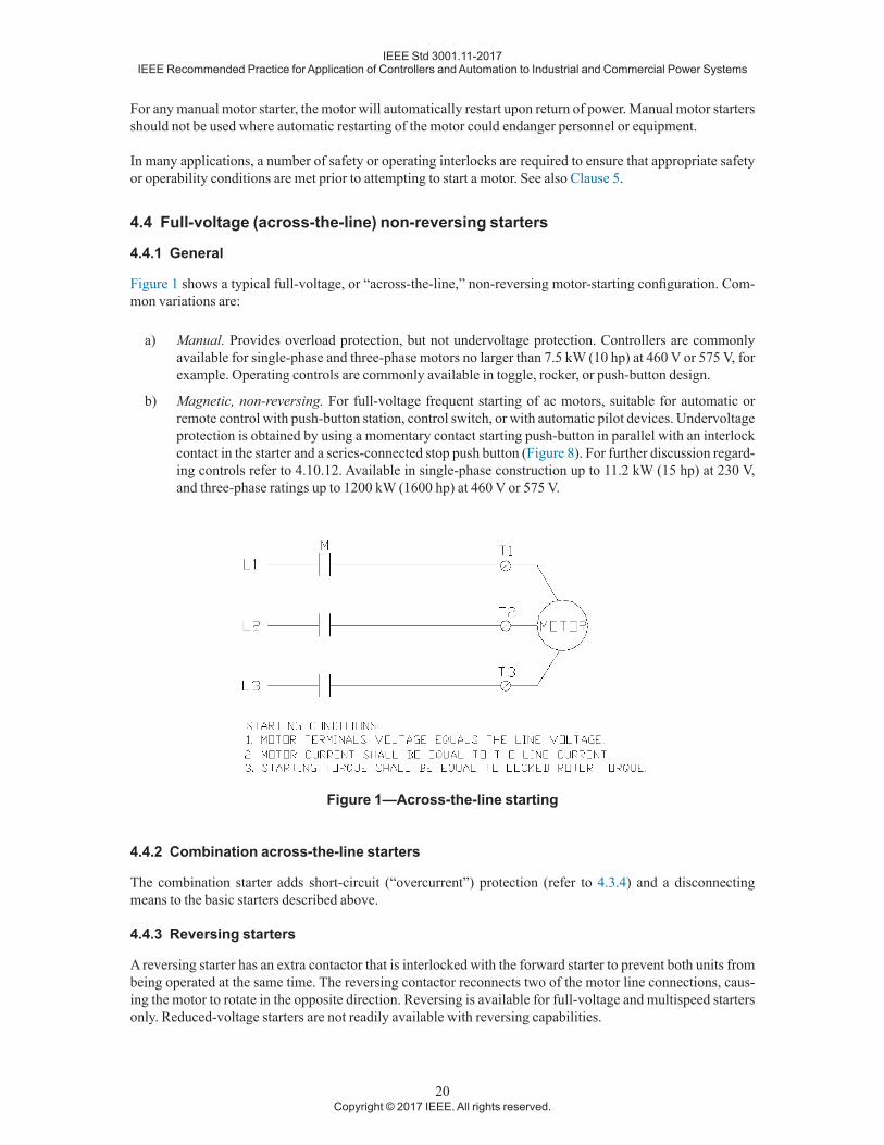
Figure 1 shows a typical full-voltage, or “across-the-line,” non-reversing motor-starting configuration. Com-mon variations are:
a) Manual. Provides overload protection, but not undervoltage protection. Controllers are commonly available for single-phase and three-phase motors no larger than 7.5 kW (10 hp) at 460 V or 575 V, for example. Operating controls are commonly available in toggle, rocker, or push-button design.
b) Magnetic, non-reversing. For full-voltage frequent starting of ac motors, suitable for automatic or remote control with push-button station, control switch, or with automatic pilot devices. Undervoltage protection is obtained by using a momentary contact starting push-button in parallel with an interlock contact in the starter and a series-connected stop push button (Figure 8). For further discussion regard-ing controls refer to 4.10.12. Available in single-phase construction up to 11.2 kW (15 hp) at 230 V, and three-phase ratings up to 1200 kW (1600 hp) at 460 V or 575 V.
Figure 1—Across-the-line starting
4.4.2 Combination across-the-line starters
The combination starter adds short-circuit (“overcurrent”) protection (refer to 4.3.4) and a disconnecting means to the basic starters described above.
4.4.3 Reversing starters
A reversing starter has an extra contactor that is interlocked with the forward starter to prevent both units from being operated at the same time. The reversing contactor reconnects two of the motor line connections, caus-ing the motor to rotate in the opposite direction. Reversing is available for full-voltage and multispeed starters only. Reduced-voltage starters are not readily available with reversing capabilities.
IEEE Std 3001.11-2017IEEE Recommended Practice for Application of Controllers and Automation to Industrial and Commercial Power Systems
21Copyright © 2017 IEEE. All rights reserved.
4.5 Reduced-voltage controllers
4.5.1 General
For some applications, such as ventilating fans or small pumps, full-voltage starting is not objectionable. As a result, most of these controllers are full-voltage types. However for many larger motors, the starting inrush current may be great enough to cause objectionable voltage sags. Some couplings or driven equipment also have limitations on the torque that may be applied without damage. Sometimes the torque limitation comes from a process constraint (e.g., controlling pipeline pressure pulsations on startup). Such maximum torque limits may require reduced-voltage starting. In other applications, sudden abrupt starts and stops may be haz-ardous, such as in an elevator, or can cause damage to other items, such as bottles on a bottling line. Some form of reduced-voltage controller should be used in these instances. Some of the benefits of reduced-volt-age starting are decreased starting torque, allowing longer life of belts, gears, couplings, pulleys, and motor shafts (which are commonly weakened with across-the-line starting) and decreased inrush current, resulting in smaller voltage sags. However, the user needs to confirm that enough torque is available with the selected controller to successfully accelerate the load. IEEE Std 399 [B27] Chapter 9 provides guidance in performing motor-starting studies.
Objectionable voltage sags are in general of two types. The first is any voltage sag which may cause unaccept-able operational issues with the facility. This can include:
— Some lights dimming when certain motors are started
— Controls mis-operating when some motors are started
— Some operating motors stalling due to undervoltage when other motors are started
The other general type of objectionable voltage sag is one that is not acceptable to the local power supply authority. Details vary with different supply authorities. Additional guidance regarding voltage issues is pro-vided in IEEE Std 141 Chapter 3.
Many kinds of reduced-voltage controllers are in common use. These controllers can be divided into the elec-tromechanical types and the solid-state controller types. Figure 2 through Figure 5 show the principles of the most common electromechanical reduced-voltage starters for squirrel-cage motors. Figure 6 shows a sol-id-state reduced-voltage controller. Table 1 provides comparisons between the various types of electrome-chanical reduced-voltage controllers.
In selecting the type of reduced-voltage controller, consideration should be given to the motor control tran-sition from starting to running. In a closed-circuit transition, power to the motor is not interrupted during the starting sequence, whereas on open-circuit transition it is interrupted. Closed-circuit transition is recommend-ed for all applications to minimize inrush voltage disturbances and associated phenomena.
Many reduced-voltage controllers are rated for short time operation only, on the basis that these devices are only intended for motor starting, which is of a short duration. Sixty second and 90 s ratings are common. After the rated time, these controllers must be bypassed and not carrying current, to allow their components to cool. Applications which may benefit from operating at reduced voltage for a longer time, including continuously, need to be examined carefully to ensure the equipment selected is suitable for this service.
4.5.2 Autotransformer type
An autotransformer starter (Figure 2) is a reduced-voltage controller that uses three contactors, a timer, and an autotransformer. It has characteristics that are similar to, but more efficient than, the resistor-reactor starter (Figure 2). An autotransformer controller reduces the voltage by transformation; the motor terminal voltage is less than the line voltage by the transformer ratio. The torque is reduced by the square of the terminal voltage. For motors up to 37 kW (50 hp), autotransformer starters usually have taps for 65% and 80% of rated voltage.

IEEE Std 3001.11-2017IEEE Recommended Practice for Application of Controllers and Automation to Industrial and Commercial Power Systems
22Copyright © 2017 IEEE. All rights reserved.
For larger motors, the taps are for 50%, 65%, and 80% of rated voltage. The torque of the motor does not in-crease with acceleration, but remains essentially constant until the transfer is made from starting to running voltage.
Closed transition starters are usually standard. In a closed transition (also known as the Korndorfer connec-tion), a smooth transition from reduced to full voltage is made. The motor is not disconnected from the line so there is no interruption in line current, which can cause a second inrush during the transition time. In an open transition starter, the motor is momentarily disconnected from the line on transfer from the starting connec-tion to the run connection. This open transition may result in some voltage disturbance. Standard motors can be used with autotransformer starters. The automatic version of an autotransformer starter, which is the most common, has a timing relay, speed relay, current relay, or other mechanism for adjustment of the time at which full voltage is applied.
There is an additional consideration when the controller (usually a contactor) is either a vacuum or SF6 inter-rupter. While modern vacuum contactors have a very low chopping current, such circuits have been reported to consistently result in substantial damage to autotransformers (Farr, et al., [B20]). This can in part be attribut-ed to the extremely short conductors interconnecting the interrupters with the autotransformers. While this is predominantly considered a medium-voltage phenomena, it should be considered for a low-voltage vacuum contactor design as well. As a minimum, when such designs are contemplated, provision should be made in the starter for installation of snubbers, which must be designed by a specialist later when detailed characteristics of the components including the autotransformer become available. Refer also to IEEE Std C57.142™ [B41].
Figure 2—Autotransformer reduced-voltage starting
Autotransformer starters are suitable for hard-to-start loads such as reciprocating compressors, grinding mills and pumps. “Hard-to-start” loads are those where the motor has to overcome a large inertia to get the load started. They are used where complete acceleration at reduced current is needed. An autotransformer starter offers the greatest amount of flexibility and is the most expensive of the electromechanical reduced-voltage starters.
4.5.3 Primary resistor or reactor type
This is the simplest reduced-voltage starting method. It uses two contactors, a timer, and either a resistor or a reactor (see Figure 3). The voltage at the motor terminals is reduced by the voltage drop across the reactor or

IEEE Std 3001.11-2017IEEE Recommended Practice for Application of Controllers and Automation to Industrial and Commercial Power Systems
23Copyright © 2017 IEEE. All rights reserved.
resistor. The inrush current is reduced proportionately (approximately). When the motor has accelerated for a predetermined interval, a timer initiates the closing of a second contactor to short the primary resistor or re-actor, connecting the motor to the full line voltage. The transition from starting to running is smooth since the motor is not disconnected during this transition. The starting torque is a function of the square of the terminal voltage. Therefore, if the initial voltage is reduced to 50%, the starting torque of the motor will be about 25% of its full-voltage starting torque. Resistor/reactor starters can be used with standard motors. Typical allowable starting times are 5 s for resistor types and 15 s for reactor types.
A three-step resistor-type starter usually does not start rotating the motor until the end of the first step. At the second step, the starting torque is 45% to 50% of normal starting torque. The time setting is also usually be-tween 3 s and 4 s. The branch-circuit protection is the same as for full-voltage starters.
Reactor-type reduced-voltage starters have somewhat better torque speed characteristics than resistor-type starters; but resistor-type starters are less expensive. Resistor-type starters have the disadvantage that the watt-age dissipation during start up can be costly for large motors that are started frequently. For this reason, re-sistor-type starters are not often used with large motors. Reactor-type reduced-voltage starters are difficult to adjust however, and are generally only used for larger medium-voltage motors. Typical applications are where current reduction requirements are low, or where torque during acceleration is minimal. These starters have smoother acceleration relative to the other types of starters. Where reactors are switched by either vacuum or SF6 interrupters, there are additional considerations, similar to the switching of an autotransformer by these controllers. See 4.5.2.
Figure 3—Series resistance and reactance reduced-voltage starting
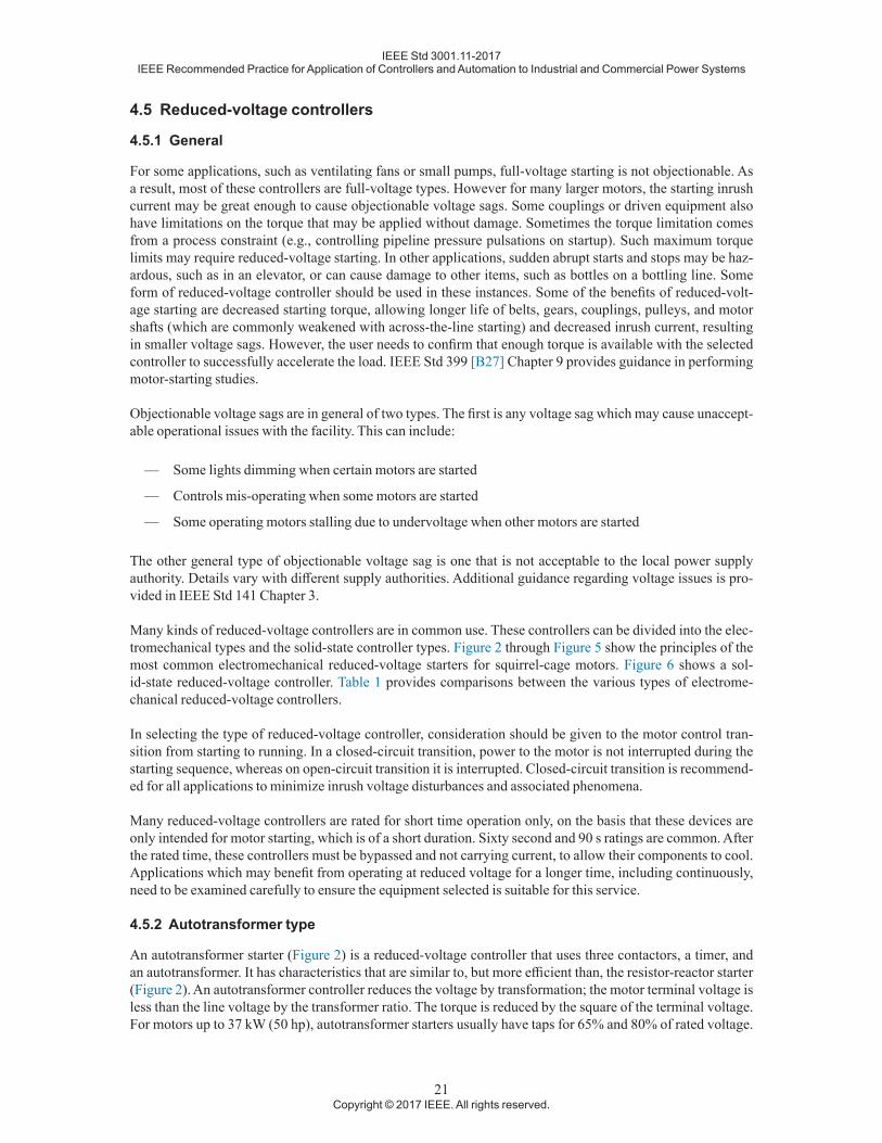
4.5.4 Part-winding type
This type of starting connects part of the winding to the supply lines for the first step, and then connects the balance in an additional step to complete the acceleration. Typically, the motor has two equal windings, but 2/3 windings are also available. The inrush current drawn from the line is about 65% of the normal inrush current. The starting torque is about 50% of the full-voltage starting torque. These numbers will vary depending upon the motor and the winding percentages. The total starting time should be set for about 2 s to 4 s. Due to severe torque dip during the transfer, the transition time should be short and at approximately half-speed.
Part-winding starting is suited to light starting (low torque) loads such as fans, blowers, motor-generator sets, and compressors with relief or unloading valves. While a part-winding starter is relatively inexpensive, the motor cost will be higher than for a normal squirrel-cage motor. Its smoothness of acceleration and application flexibility are poor.
IEEE Std 3001.11-2017IEEE Recommended Practice for Application of Controllers and Automation to Industrial and Commercial Power Systems
24Copyright © 2017 IEEE. All rights reserved.
Figure 4—Part-winding starting
4.5.5 Wye-delta type
In a wye-delta starter (also known as star-delta), the motor’s internal connections are changed. They are wye connected for starting and delta connected for running. This causes the impedance seen for starting to be three times that for running, reducing the starting current. Starting current and torque are approximately 33% of nor-mal. As with autotransformer starters, these starters can be either open or closed transition types. For closed transition, resistors are used. In this instance, ventilation is required to remove the heat from the resistors. Open transition starters will have a severe current peak at the transition. The branch-circuit protection has to be selected very carefully for open transition starters so as to avoid tripping during transition. The time setting should be set somewhat longer than for part-winding starters; that is, 3 s to 4 s on open transition, and 3 s to 5 s on closed transition autotransformer and wye-delta starters. On closed transition wye-delta and autotrans-former starters, the standard branch-circuit protective device is selected in the same manner as are full-voltage starters.
Wye-delta starters are suitable for high inertia loads with long acceleration times, such as centrifugal com-pressors and centrifuges. They can also be used where the load torque during acceleration is low. Wye-delta starters are extensively utilized in Europe and in the United States, particularly for large air-conditioning units. Six- or 12-lead delta connected motors can also be wye started using this type of starter. The starter cost is somewhat more expensive than a part-winding starter, and like the part-winding starter, the motor cost is also higher than a standard motor.

IEEE Std 3001.11-2017IEEE Recommended Practice for Application of Controllers and Automation to Industrial and Commercial Power Systems
25Copyright © 2017 IEEE. All rights reserved.
Figure 5—Wye-delta reduced-voltage starting
A comparison of starting currents and torques produced by various kinds of reduced-voltage starters is shown in Table 1.
Table 1—Comparison of electromechanical reduced-voltage starters— Autotransformera Primary resistor
or reactor Part windingb
Wye delta50% tap
65% tap
80% tap 65% tap 80% tap 2-step 3-step
Starting current drawn from line as percent-age of that which would be drawn upon full-voltage startingc
28% 45% 67% 65% 80% 60% 25% 331/3%
Starting torque developed as percentage of that which would be developed on full-voltage starting
25% 42% 64% 42% 64% 50% 12 1/2% 331/3%
Increases slight-ly with speed
Increases great-ly with speed
— — —
Table continues

IEEE Std 3001.11-2017IEEE Recommended Practice for Application of Controllers and Automation to Industrial and Commercial Power Systems
26Copyright © 2017 IEEE. All rights reserved.
— Autotransformera Primary resistor or reactor Part windingb
Wye delta50% tap
65% tap
80% tap 65% tap 80% tap 2-step 3-step
Smoothness of ac-celeration
Second in order of smoothness
Smoothest of re-duced-voltage types. As motor gains speed, cur-rent decreases. Voltage drop across impedance decreases and motor ter-minal voltage increases.
Fourth in order of smoothness
Third in order of smoothness
Installed cost High High Low MediumStarting current and torque adjustment
Adjustable within limits of various taps
Adjustable within limits of various taps NA NA Fixed
aClosed transition.bApproximate values only. Exact values can be obtained from the motor manufacturer.cFull-voltage start usually draws between 500% and 650% of full-load current.
4.5.6 Solid-state type
Most solid-state controllers (also known as “soft starters”) are of the reduced-voltage type. These are readily available for both low-voltage and medium-voltage motors. There is another variation of solid-state controller, the reduced-frequency type, which at present is semi-custom, and requires working with the applications en-gineers of the selected manufacturer. The reduced-frequency controller uses an adjustable-speed drive (ASD) to start the motor. ASDs are discussed in more detail in 4.10. Normally a reduced-voltage controller will be selected. However, for applications where the load torque will exceed the available starting torque at reduced voltage, the reduced-frequency controller will be needed.
Most solid-state controllers of either type are rated for short time operation only. Sixty-second and 90-s rat-ings are common. After the rated time, these solid-state controllers must be bypassed and not carrying cur-rent, to allow their components to cool. For some applications, detailed calculations will be required to deter-mine the necessary component ratings, and components approaching a continuous current carrying version may be required. This will affect the size and cost of the solid-state controller, especially for medium-voltage applications.
Solid-state, or electronic, reduced-voltage (SSRV) controllers provide very similar motor output torque and inrush currents as an autotransformer, but with more options. They are designed to decrease inrush current to the motor during starting and limit the available starting torque by more smoothly ramping the voltage. The amount of starting current is field adjustable by the user, within certain limitations. Three methods of acceler-ation are available:
1) Constant current acceleration: the motor is accelerated to full speed at a field-selectable, preset current level.
2) Current ramp acceleration: the voltage is gradually increased to provide smooth, stepless acceleration under varying loads.
3) Linear timed acceleration: the motor is accelerated at a linear rate that is field-adjustable (tachometer feedback circuit required).
One simple type of reduced-voltage motor controller uses six thyristors in a full-wave configuration to vary the input voltage from zero to full on, so that the motor accelerates smoothly from zero to full running speed. The thyristors are activated by an electronic control section that has an initial step voltage adjustment. This ad-
Table 1—Comparison of electromechanical reduced-voltage starters (continued)

IEEE Std 3001.11-2017IEEE Recommended Practice for Application of Controllers and Automation to Industrial and Commercial Power Systems
27Copyright © 2017 IEEE. All rights reserved.
justment, combined with a ramped voltage and current-limit over-ride, can provide constant current (torque) to the motor until it reaches full speed.
Variations in the design of starting circuit are as follows:
a) Three power diodes replace the three return-conducting thyristors. The control circuit is simple and each thyristor is protected against reverse voltage by its associated diode. This half-wave configura-tion will produce more harmonics than the full-wave configuration, and generate added heat in the motor windings. Thermal protective devices should be properly sized to prevent this additional heat from damaging the motor.
b) Thyristors are used only during the starting phase. At full voltage, a run contactor closes and the circuit operates as a conventional electromechanical starter. This is the most common configuration used for large motors.
c) A controller with linear-timed acceleration uses a closed-loop feedback system to maintain the motor acceleration at a constant rate. The required feedback signal is provided by a tachometer coupled to the motor.
These controllers are readily available for motors rated from fractional horsepower to thousands of horsepower.
SSRV controllers are particularly suitable for applications that require extremely fast or a large number of operations, or both (several million under load). Applications include conveyors, elevators, compressors, ma-chine tools, pumps, and fans. To a limited extent, they can also be used for speed control and other functions for ac and dc motors. SSRV controllers have some benefits that other reduced-voltage starting methods lack. Most SSRV controllers have an option to reduce the voltage when motor loading is low. This provides an op-portunity for energy savings during light loading conditions. Another advantage is smooth seamless starting with an infinite number of torque/current settings, giving the SSRV controller superior flexibility.
4.6 Wound-rotor motor controllers
The wound-rotor or slip-ring motor functions in the same manner as the squirrel-cage motor, except that the rotor windings are connected through slip rings and brushes to external circuits with resistance to vary motor speed. Increasing the resistance in the rotor circuit reduces motor speed and decreasing the resistance in-creases motor speed. Some variations of this type of controller employ thyristors in place of contactors and resistors. Some even rectify the secondary current and invert it to line frequency to supply back into the input, appreciably raising the efficiency.
4.7 Multispeed motor controllers
These controllers are designed for the automatic control of two-, three-, or four-speed squirrel-cage motors of either the consequent-pole or separate-winding types. They are available for constant-horsepower, con-stant-torque, or variable-torque three-phase motors used on fans, blowers, refrigeration compressors, and sim-ilar machinery.
Multiple speed motors are used to obtain different predefined motor speeds from a single motor. There are two types of multiple speed motors: consequent pole and separate winding. Consequent pole motors have a winding for every two motor speeds while separate winding motors have a winding for each speed. The speed ratios for consequent pole motors are typically limited to a 2:1 ratio. The controller is designed for two steps, and speed cannot be varied in a wide, stepless range. If greater flexibility is desired, separate winding motors should be used. Both motors are available for constant horsepower, constant torque, and variable torque appli-cations. Controllers for consequent pole and separate winding motors have different numbers of poles in the contactors. The consequent pole controller has a five-pole and a three-pole contactor. The separate winding controller has two three-pole contactors. Before a controller is selected, the type of motor needs to be known.

IEEE Std 3001.11-2017IEEE Recommended Practice for Application of Controllers and Automation to Industrial and Commercial Power Systems
28Copyright © 2017 IEEE. All rights reserved.
A two-speed motor and starter is an example of a multispeed motor application. A two-speed motor requires six overloads, three for each speed.
Figure 6—Solid-state reduced-voltage starting
Typical applications for multispeed motors include spindles, cutting tools, conveyors, reciprocating pumps, fans, and centrifugal pumps. Some applications may require additional relays when switching between speeds.
4.8 Single-phase motor starting
Starting single-phase motors can also result in inrush currents and voltage sag. However, single-phase mo-tors are generally much smaller than three phase. Typical design specifications limit the rating of 120 V sin-gle-phase motors to under 1 kW (1.5 hp). Magnetic starters can be used to start single-phase motors. However, many of these applications use manual motor starters. Manual starters provide ON/OFF control, and are either fractional horsepower or integral horsepower type.
Fractional horsepower starters are for control of one- and two-pole motors (115 V or 230 V) that are 0.75 kW (1 hp) or less. They have overload protection and are operated by a toggle switch handle. Integral horsepower controllers are for single-phase motors of 4 kW (5 hp) or less and three-phase motors of 7.5 kW (10 hp) or less. They also have overload protection and have start-stop pushbutton operation.
IEEE Std 3001.11-2017IEEE Recommended Practice for Application of Controllers and Automation to Industrial and Commercial Power Systems
29Copyright © 2017 IEEE. All rights reserved.
4.9 Controllers for dc motors
DC motors have favorable speed-torque characteristics and their speed is easily controlled. They are started by either full voltage or reduced-voltage starting methods. Generally, full-voltage starting is limited to motors of 1.5 kW (2 hp) or less because of very high starting currents. Reduced-voltage starting is accomplished by inserting a resistance in series with the armature winding. As counter-electromotive force builds up in the ar-mature, the external starting resistance can be gradually reduced and then removed as the motor comes up to speed. This is done by either a current relay or by timers in steps. All resistance should be removed from the circuit as soon as the motor reaches full speed. Motor characteristics and the resistors are different for series and for shunt motors. The speed of a dc motor is proportional to the counter electromotive force and inversely proportional to field strength. Thus, speed control of dc motors can be accomplished by varying the resistance in the shunt or series fields or in the armature circuit. Reversing is accomplished by reversing the flow of cur-rent through either the armature or the field.
4.10 Adjustable-speed drives (ASDs)
4.10.1 Introduction
The continuing advancement of semiconductor devices is enhancing the design and application of solid-state drives for dc and ac motors’ speed controls. Semiconductor devices like diodes, thyristors, transistors, gate-turn-off switches (GTOs), gate commutated thyristors (GCTs), and insulated gate bipolar transistors (IGBTs) are available with high current-carrying capacity. The control systems aided by microprocessors, digital elec-tronics, and advanced signal processing offer reliable and highly accurate speed control. The cost and perfor-mance advantages of these drives compared to that of earlier drives—such as a motor generator (MG) set for dc, and eddy current for ac—is significant.
4.10.2 DC adjustable-speed drives
In industrial ASDs, dc motors have historically been the prime choice for speed control based on their adapt-ability to wide ranges of speed-serving duties of small to several thousand horsepower mechanical demands. A dc motor’s speed can be changed by varying the armature voltage or field current, as required by different load characteristics:
a) Constant torque. Armature voltage-controlled dc drives are constant-torque drives. Between zero and rated speed, the current is constant at rated value with a constant voltage.
b) Constant horsepower. Field voltage-controlled devices are constant horsepower type required for a specified speed range.
c) Variable torque. Armature current is a function of motor load. To maintain the limit to rated current, the motor load decreases resulting in decrease of torque above the base speed.
The trend of the application of dc ASDs had been declining due to the commutators’ high expense and main-tenance requirements. Those problems are being overcome, however, with the introduction of new brushless technology.
4.10.3 AC adjustable-speed drives
4.10.3.1 Introduction
In industry the choice of ac drives over dc drives for speed control is popular in many applications. Modern ac ASDs are implemented as variable frequency drives (VFDs). As ac VFD performance continues to improve, this trend is expected to continue. The following features make squirrel-cage induction motors widely accept-ed in industry:

IEEE Std 3001.11-2017IEEE Recommended Practice for Application of Controllers and Automation to Industrial and Commercial Power Systems
30Copyright © 2017 IEEE. All rights reserved.
— Simplified design with high reliability
— Rugged construction suitable for all environments
— Low initial cost
— Low operating cost
— Low maintenance cost
— High efficiency
4.10.3.2 Fundamentals of ac motor speed control
For any mechanical output of a motor, the two basic parameters to be controlled are speed and torque. The fun-damental equations defining operating parameters of ac motors are expressed in Equation (1) and Equation (2).
N fps =
120 (1)
sN NN
s FL
s
=−( )
×100% (2)
where
Ns is the synchronous speed, rpmf is the power supply frequency, Hzp is the number of poless is the slip of the rotor, in percentNFL is the full-load speed of the motor, rpm
The speed of an ac motor can be controlled by changing either of the following parameters:
a) The pole pairs. The pole-changing method gives a stepped control of speed. In general, pole-changing is done for two-speed motors utilizing combination motor starters.
b) The supply frequency. Varying the supply frequency gives a stepless, or smooth, variation of speed, which can be easily achieved.
c) Slip control. The principle of speed control by “slip” is applied by using stator voltage controls, slip power recovering, or rotor resistance control. However, torque and speed control cannot be performed independently with this method.
4.10.3.3 Torque control
The motor’s torque is proportional to the magnetic flux density of the air gap between a motor’s rotor and sta-tor. Considerations for some common load characteristics are:
a) Constant torque. The flux density needs to be maintained constant over the operating frequency range to keep the torque constant. On the other hand, the impedance of the motor varies directly with the supply frequency. Increasing supply frequency increases the motor impedance. In this event, the sup-ply voltage should be increased to maintain the air gap voltage constant to create constant flux density. Therefore, a constant flux density is dependent on a constant volt to frequency ratio, V/f. The ratio, V/f, is controlled by convertors. At low-speed or low-frequency range, the effect of resistance in com-parison to the effect of reactance (termed IR compensation) is significant enough to raise the supply voltage above the V/f requirement in order to maintain the air-gap-flux constant.

IEEE Std 3001.11-2017IEEE Recommended Practice for Application of Controllers and Automation to Industrial and Commercial Power Systems
31Copyright © 2017 IEEE. All rights reserved.
b) Constant horsepower. Above the rated value of speed, the rated voltage remains the same as the supply voltage. The air-gap flux decreases inversely to the frequency, and the torque decreases inversely to the square of the frequency at nearly constant “slip.” This is the constant horsepower range of speed control.
4.10.3.4 Types of ac VFDs
The major categories of ac VFDs in use in industry are as follows:
a) Voltage source inverter (VSI). For voltage source topologies, the output of the inverter is a voltage. The motor and its load (not the inverter) determine the current that flows in the circuit. The primary identifying characteristic for these drives is that the dc link is capacitive. Typically, these drives have diode (passive) rectifiers on the input often in the form of multi-pulse bridges, however, active front ends are becoming a more common option.
b) Current source inverter (CSI). The output of a current source inverter is a current. The motor and its load (not the inverter) determine the voltage. This topology utilizes an active front end rectifier and the dc link element is an inductor rather than a capacitor. Current-fed inverters utilize the line converter (rectifier) to control the dc link voltage and current and thus the amplitude of the output. The prima-ry purpose of the output inverter is to manage conduction as well as to control the frequency of the output. Link energy storage is relatively low and the dc link reactor provides immunity to faults and grounds. Since the current is regulated, inverter faults do not cause high currents.
Microprocessor control of ac VFDs, which is common in all modern products, is causing ac drives to replace dc drives. The microprocessor’s application for vector control of characteristics of ac induction motor torque and magnetizing components is one of the predominant features that supports the application of ac drives over dc drives.
4.10.4 Specification of ASDs
In general, ASDs should be sized per their maximum current requirements under peak torque demands. Based on the functional description of mechanical and process requirements, the following criteria should be ana-lyzed and addressed in the specification of the drives:
a) Speed torque curve of the mechanical load
b) Speed range and regulation
c) Break-away torque
d) Dynamic response (Wk2) to the motor shaft, including acceleration and deceleration time
e) For large motors with high-speed operation, mechanical resonance effect of gears, couplings, shafts, and flywheels
f) Motor voltage
g) Input voltage dips and variations
h) Frequency variations
i) Incoming power, voltage dips, and regulation
j) Ride-through requirements and response to momentary interruption
k) Harmonic current and its effect on a plant’s power-distribution apparatus, especially to microproces-sor-based equipment and electronically sensitive instruments
l) Harmonic current’s effect on mechanical output, such as torque and pulsation
IEEE Std 3001.11-2017IEEE Recommended Practice for Application of Controllers and Automation to Industrial and Commercial Power Systems
32Copyright © 2017 IEEE. All rights reserved.
m) Environment requirement of the drive and its effect on the performance (ambient temperature, hazard-ous, non-hazardous classified area, climate-controlled room or enclosure)
n) Diagnostics and alarms requirement
o) Hardware requirement like control console, video displays, etc.
p) Interface to other control equipment such as programmable logic controllers (PLCs), distributed con-trol systems (DCSs), and hard-wired operator stations
q) Serial/parallel-type computer interfaces for supervisory control and recipe downloading
r) Starting and stopping cycles for energy-management applications
s) Load braking and regeneration applications
Reference should also be made to IEEE Std 1566™ [B36], NEMA 250 [B62], ICS 7 [B70], ICS 7.1 [B71], ICS 61800-2 Part 1 [B73], ICS 61800-2 Part 2 [B74], and ICS 61800-4 Part 4 [B75] (as appropriate).
For medium-voltage drives, reference should be made to IEEE Std 1566 [B36].
4.10.5 Harmonics and ASDs
ASDs are non-linear. As stated in IEEE Std 519™ [B31], “Nonlinear loads change the sinusoidal nature of the ac power current (and consequently the ac voltage drop), thereby resulting in the flow of harmonic currents in the ac power system that can cause interference with communication circuits and other types of equipment.”
Harmonics are, as defined in the IEEE Standard Dictionary, “a sinusoidal component of a periodic wave or quantity having a frequency that is an integral multiple of the fundamental frequency.” Harmonics are also a steady-state phenomena. In the United States, the fundamental frequency is 60 Hz. Therefore the harmonics are 120 Hz, 180 Hz, 240 Hz, etc. Most non-linear devices produce primarily odd harmonics (60n where n = 1, 3, 5...). This is true for ASDs.
The current distortions from the non-linear devices produce voltage distortions as they pass through the system impedances. These distortions affect all of the power system components: capacitors, transformers, motors and cables. As discussed in Duggan, et al. [B15], “harmonic voltage distortion at motor terminals is translated into harmonic fluxes within the motor...additional fluxes do little more than induce additional loss-es. Decreased efficiency, along with heating, vibration and high-pitched noises are symptoms of harmonic voltage distortion.” At higher frequencies, the resistance is no longer a constant, but increases, producing heat that has to be dissipated somewhere. Increased heating means increased losses. Increased heating also shortens the life of the insulation on cables and windings. Harmonics can cause mechanical resonances. Har-monics can cause false operation of circuit breakers, protective relays, or fuses. Transformers can experience overheating due to the increased iron and copper losses. Another potential problem is an interaction between multiple ASDs so that one or more of them do not operate correctly. Distorted sine waves can have multiple zero crossings, which can yield incorrect operation in electronic or solid-state devices. Measuring instruments that are not the true rms type will not measure accurately where there are harmonics present. Another concern with harmonics from ASDs is that a harmonic component can excite a resonant condition between a power factor improvement capacitor bank and the inductance of the power system, causing damaging overvoltages to appear at or near the capacitors. When ASDs are connected with capacitor banks or active filters, additional study is advised to minimize operational problems.
“The harmonic current distortion in adjustable-speed drives is not constant. The waveform changes signifi-cantly for different speed and torque values” (Duggan, McGranaghan, and Beaty [B17]). The drive manufac-turer may be able to provide some type of harmonic analysis if there is a question as to whether a particular drive, or set of drives, will cause problems. Refer to IEEE Std 399 [B27] Chapter 10 for guidance regarding harmonic analysis studies. This analysis should be done at the point of connection between the drives and the rest of the system, not at the point of common coupling with the utility. If harmonics are a problem, a line

IEEE Std 3001.11-2017IEEE Recommended Practice for Application of Controllers and Automation to Industrial and Commercial Power Systems
33Copyright © 2017 IEEE. All rights reserved.
reactor can be added to reduce the harmonic levels. The addition of harmonic filters or “traps,” either passive or active, is a possible solution. However, the addition of any filters of any nature requires detailed analysis before proceeding.
4.10.6 Common application issues of ASDs
ASDs generate more heating in the connected motor than a “regular” starter due to the non-sinusoidal cur-rents. This excess heating can cause damage to electrical insulation. ASDs generate more heat than electro-mechanical motor controllers, which needs to be managed. Motors to be used with ASDs should be specified as listed for inverter duty. ASDs generate voltage spikes, and standing or reflected waves due to the difference in impedance between the motor and the cable connecting the drive to the motor. Some ASD designs impose common mode voltages on the motor such that standard design motors should be expected to fail in normal service. A pulse-width modulation (PWM) drive has a high switching frequency, which yields fast rise times for the voltage peaks. These spikes and waves can damage wiring insulation, both in the motor and in the cable between the motor and drive. One way to mitigate this is to specify a motor with the appropriate insulation. The cable between the motor and drive may also need special consideration. Some companies now manufac-ture a cable specifically for use with ASDs; the need for this special cable as contrasted with a more common armored cable (e.g., MC in NEC jurisdictions or TECK in CE Code jurisdictions) continues to be debated. The ASD should also be located as close as possible to the motor it serves to minimize the effects of reflected or standing waves. Particular drive manufacturers may also have some distance limitations or recommenda-tions. As this is impossible in many industrial facilities, especially where suitable non-hazardous locations for electrical rooms are difficult to arrange, many manufacturers have designed additional equipment intended to minimize the impact of the reflected wave on the motor, although often with cable length limitations. There are grounding implications to installing ASDs, especially in conjunction with high resistance grounded systems. Harmonic torques may need to be addressed. Harmonic induced shaft currents usually need to be mitigated. A number of IEEE papers have been written regarding various aspects of the application of ASDs to industrial motors, including Blair, et al. [B12], Busse, et al. [B14], Erdman, et al. [B18], Kerkman, Legatte, and Skibins-ki [B56], Leggate, et al. [B58], and Melfi, et al. [B59].
A common reason for using ASDs is energy savings. With an ASD, the motor doesn’t run at full load or speed when it is not needed. Depending upon the size of the motor, the hours of lightly loaded operation, and the cost of electricity, this can yield significant savings. Additionally, ASDs can improve control and efficiency, and are often more economical than throttling dampers or valves. Sometimes ASDs are installed to manage motor-starting issues, although they are more expensive than most other controllers when motor starting is the only consideration. The use of ASDs for certain motors and applications may also be mandated by state or local energy codes.
4.11 Controller arrangements
Controllers are provided in any of the following physical arrangements:
a) Disconnecting means and controller in separate, discrete enclosures
b) Disconnecting means and controller in a single, combined enclosure
c) Controllers as part of a motor control center
d) Controllers as part of a specialized equipment package, e.g., a chiller control panel or an air compres-sor control panel.
e) A common variant is the duplex starter, which is used in some pumping applications, such as sump pumps or sewage ejector pumps. It is composed of two starters in one common enclosure. Each starter controls a motor. Typically, only one of the motors runs at a time. In a situation where a peak demand or other load increase requires it, the second motor would start. Which motor runs is determined by ei-ther a run-time counter, or by the last start. This is to evenly spread the wear and tear over both motors and starters. If both motors can run at the same time, either temporarily to avoid process interruptions,

IEEE Std 3001.11-2017IEEE Recommended Practice for Application of Controllers and Automation to Industrial and Commercial Power Systems
34Copyright © 2017 IEEE. All rights reserved.
or continuously to manage higher demand loads, the supply system must be sized accordingly. If the supply can only accommodate one motor running at a time, there will be some protection and control issues which must be addressed.
4.11.1 Controller options and accessories
In addition to the overload protection, overcurrent protection, and other protective options, many features and additional components can be added to motor controllers. These items are added to make the motors and drives perform particular functions, to provide monitoring of the motors, for the convenience of the user or mainte-nance staff, or to provide additional protection to the motors and systems.
Auxiliary contacts, either normally open or normally closed, can be provided to interlock the motor with other motors or systems, including safety systems. Unloading devices on compressors are frequently interlocked with the motor control to assure that the motor will not attempt to start if the compressor is loaded, and will unload the compressor if the load exceeds the available motor torque. Vanes and dampers in air systems, and valves in liquid systems, may be similarly interlocked with the motor controller. If the building requires con-veying systems to handle materials, interlocking between motor controllers can assure the proper sequencing of the starting and stopping of the conveyor drives. Sometimes certain exhaust and supply or make-up air fans will be interlocked. Auxiliary contacts can also be used to control other systems based upon the status of the motor.
Pilot lights can be added to indicate the status of the motor. Selector switches may be “ON/OFF,” “HAND/OFF/AUTO,” “Forward/Off/Reverse,” etc. These switches may also be key operated for greater security. Push buttons, for “Stop/Start,” “High/Low/Off,” etc. may also be specified. A remote reset option allows the over-load relays to be reset from a remote location, rather than at the controller. Motor run-time meters can be add-ed. For VFDs, a bypass isolation switch can be specified. This allows the motor to be run with a full-voltage, or other type of, starter while the VFD is being replaced or undergoing maintenance. Metering is available to measure amperes, volts, watts, and power factor if needed. Modules are available for communication with the building automation system (BAS) or other control system. Time delays can be provided. Special treatments, such as a fungicidal treatment, and special finishes are also available.
There are a number of specialized controller configurations. A variation of reduced-voltage starting, which was popular prior to the commercial availability of large VFDs, was to combine capacitor-assisted starting with either autotransformer starting (4.5.2) or reactor starting (4.5.3).18 Another is what has been termed a dual bus motor control center (MCC), where one VFD is shared with a number of identically rated motors; one motor at a time is started on the VFD, run to speed, synchronized across the line, and transferred from the VFD bus to the line bus, then the next is connected to the VFD bus and started. This scheme has been popular in pipeline pumping applications, where a number of motor-driven pumps are connected as one unit. These and other specialized applications are not discussed in detail in this standard. They are all constructed from a number of items which are discussed in this standard. Any specialized issues unique to a given application can generally be identified by searching for papers in the IEEE Industry Applications publications and conference records.
4.11.2 Controller sizes and selection
Sizes for NEMA starters are based upon the motor voltage and horsepower ratings. Table 2 below gives the horsepower limits for the standard NEMA sizes. Refer to NEMA ICS 2 for more detailed information. Addi-tional information is needed to size IEC starters.
If the motor is to be used for plugging or jogging duty, the starter size required may be different. Jogging is the frequent stopping and starting of the motor for short periods of time. As a rule of thumb, more than three
18The comments in 8.9.3.2 of IEEE Std 141 regarding over-excitation of induction motors are relevant to capacitor-assisted starting schemes.

IEEE Std 3001.11-2017IEEE Recommended Practice for Application of Controllers and Automation to Industrial and Commercial Power Systems
35Copyright © 2017 IEEE. All rights reserved.
evenly spaced start and stop operations within an hour is considered frequent. Plugging is when a motor is momentarily connected to the reverse direction, bringing it quickly to a stop.
Table 2—NEMA standardized starters and contactorsSize 00 0 1 2 3 4 5 6 7 8 9
Rated current closed (A) 9 18 27 45 90 135 270 540 810 1215 2250Rated current open (A) 10 20 30 50 100 150 300 600 900 1350 2500hp at 480 V/600 V 2 5 10 25 50 100 200 400 600 900 1600hp at 208 V 1.5 3 7.5 15 30 50 100 200 300 450 800
Motor sizes for mechanical equipment are not usually determined by the electrical engineer or electrical de-signer, unless the electrical system imposes an upper limit on the motor and mechanical equipment size. Typ-ically, the application the motor is serving determines the motor size. Process pump or compressor loads and reference standards determine the motor sizes. Heating, ventilating, and air conditioning (HVAC) require-ments in a building will determine the fan and pump motor sizes required. The number of stops, load capacity, and elevator type determines the motor size of an elevator. The manufacturer’s literature should be consulted.
Some loads are capable, under some operating conditions, of overloading a motor which is correctly sized in accordance with the relevant standards. These conditions need to be assessed by the designer; protection to avoid operating in these overload conditions may be required. This may include provision to start an additional pump or compressor, e.g., in some non-critical applications, it may be decided to allow the motor to trip on overload, forcing operator intervention.
Selecting the type of motor starter depends upon several factors. These include motor size, control application, cost, NEMA design type of motor, and whether the motor is new or existing (ASDs can cause problems when applied to some existing motors). Some applications may require a two-speed or multi-speed motor, in which case a two- or multi-speed starter needs to be specified. There is no set point above which reduced-voltage controllers should be used. Typically, in many commercial applications, for motors above 22 kW (30 hp) to 30 kW (40 hp), some type of reduced-voltage controller should be used unless the application cannot support the reduced starting torque or extended acceleration times. However, some large industrial applications success-fully start motors in excess of 15 MW (20 000 hp) across the line. The local utility company may have some restrictions on the amount of inrush they can tolerate at their equipment. For some pieces of equipment, such as fire pumps, chillers, and elevators, the manufacturer typically provides the controller with the equipment. Motor operated valves (MOVs) are routinely available either with or without integral controllers. The decision as to whether to use separate starters and disconnects, combination starters or a motor control center depend upon the quantity and size of the motors, the location, and any space constraints.
A variable frequency drive needs to be matched to the motor it will be controlling so that the horsepower and torque ratings are compatible. Its output voltage and frequency need to be the same as the motor’s rated voltage and frequency.19 This can be a problem when replacing an existing motor starter with an ASD. If the horsepower and torque characteristics don’t match, the system may not work properly, or may not work at all. The voltage spikes associated with an ASD may also cause problems with the insulation of an existing motor.
4.11.3 NEMA versus IEC
The National Electrical Manufacturer’s Association (NEMA) is a body that writes standards governing elec-trical equipment. These standards are commonly used in the United States and Canada. The standard for motor control products is NEMA ICS 2. In the international community, the reference standard making body is the
19Sometimes motors are driven “over-speed” by a VFD, but this should always be within the limits stated by the motor manufacturer.

IEEE Std 3001.11-2017IEEE Recommended Practice for Application of Controllers and Automation to Industrial and Commercial Power Systems
36Copyright © 2017 IEEE. All rights reserved.
IEC, or International Electrotechnical Commission.20 IEC is used by European countries and most many other countries worldwide. IEC 60947-4-1 [B22] is the standard governing contactors and motor starters.
While NEMA and IEC contactors and starters perform the same functions, they are designed and specified differently, and each has its advantages and disadvantages. NEMA devices are general purpose devices, as opposed to the more application-specific IEC devices. NEMA devices are designed to be more robust, and to have a wider range of applications. They are easy to select; the only information needed is the motor horse-power and the voltage, and they have interchangeable elements. Standard sizes are available from many man-ufacturers and are typically sold fully assembled. IEC devices are more application specific. More knowledge of the motor and application is needed to select an IEC device. Motor load, duty cycle, and full-load current need to be known. IEC contactors are available in a wide range of sizes allowing a closer match to the load. For ratings less than 100 A, IEC starters are physically smaller than their NEMA counterparts. They are typically sold as components rather than fully assembled, and are more modular in nature. There is a fundamental differ-ence in design philosophy between NEMA and IEC starters, which should be appreciated when applying the equipment. Refer to NEMA ICS 2.4 [B66] as a general guide to the differences between systems.
NEMA and IEC also express themselves differently when it comes to how motors are specified. NEMA spec-ifies motors by output (“shaft”) horsepower, IEC by output power expressed in kW. Frame sizes are different as the IEC works in metric units. NEMA has duty cycle classes of continuous, intermittent, and special duty. IEC has eight classes, ranging from continuous duty to intermittent periodic duty with electric braking to continuous operation with periodic changes in load and speed. Other differences are in enclosure designation. NEMA historically uses words, such as “Open Drip Proof,” while IEC uses a two-digit identification number indicating the degree of protection from the entry of solid objects and from water entry. For example, an IEC IP 23 motor correlates to a NEMA Open Drip Proof. IEC also uses a two-digit code to indicate how a motor is cooled. (These IEC protection and cooling designations have been incorporated in NEMA MG-1 for some time now, although many users in North America are not familiar with them.) NEMA has design classes A, B, C, and D. IEC also has design classes that are similar to NEMA, but the letters are different. For a complete listing of the types and descriptions of enclosures, reference the appropriate NEMA or IEC standard.
4.11.4 Motor control centers
Most motor control centers (MCCs) are tailor-made assemblies of conveniently grouped control equipment primarily used for power distribution and associated control of motors. They contain all necessary buses, incoming line facilities, and safety features to afford the maximum in convenience by saving space and labor and by providing adaptability to ever-changing conditions with a minimum of effort and a maximum of safety. The motor control center consists of a number of basic vertical structures. Each vertical structure has a vertical bus system connected to a horizontal bus system. The horizontal bus system is either behind, on the top, or on the bottom of the vertical bus system. Each vertical section has a number of basic units, which consist of combination or unitized combination starters with or without control transformers; combination reversing, or multiple-speed starters; reduced-voltage controllers, etc. These units are prefabricated and can be plugged into the vertical bus structure. (Some large amperage units are hard wired to the bus rather than plug [or “stab”] connected.) All compartments are multiples of a basic dimension. Common low-voltage NEMA MCC dimen-sions are approximately 90 in high with section widths of 20 in. The modular design of an MCC simplifies in-stallation, wiring, and application, especially for a large number of motors. Individual components in an MCC are no different than those in individually mounted controllers.
NEMA ICS 2 (and certification standard UL 845 [B93]) governs the type of enclosure and wiring for low-volt-age equipment; NEMA Type 1, 2, and 12 enclosures are generally available. Wiring of motor control centers conforms to two NEMA classes and three types. Class I provides for no wiring by the manufacturer between compartments of the center. Class II requires prewiring by the manufacturer with interlocking and other con-trol wiring completed between compartments of the center. With Type A, no terminal blocks are provided;
20There are some exceptions to this. There are a few countries that maintain their own unique variety of standards. There are a few countries outside of North America which use the NEMA/ANSI standards. There are some countries which, for historic reasons, have a system which is effectively a mixture of IEC and NEMA/ANSI practices.

IEEE Std 3001.11-2017IEEE Recommended Practice for Application of Controllers and Automation to Industrial and Commercial Power Systems
37Copyright © 2017 IEEE. All rights reserved.
with Type B, all connections within individual compartments are made to terminal blocks; and with Type C, all connections are made to a master terminal block located in the horizontal wiring trough at the top or bottom of the center. The ideal wiring specification for minimum field installation time and labor is NEMA Class II, Type C wiring. The wiring specification most frequently used by industrial contractors is Class I, Type B wiring. Refer to NEMA ICS 2 for definitions of wiring classes and types.
NEMA ICS 18 [B72] specifies that a motor control center shall carry a short-circuit rating defined as the max-imum available rms symmetrical current in amperes permissible at line terminals. The available short-circuit current at the line terminals of the motor control center is computed as the sum of maximum available current of the system at the point of connection and the short-circuit current contribution of the motors connected to the control center. UL-listed motor control centers must be marked with the short-circuit rating as determined by the device in the assembly with the lowest short-circuit rating. However, it is common practice by many manufacturers to show only the short-circuit rating of the bus-work on the nameplate of equipment that is not UL listed. As a result, it is very important to establish the actual rating of the entire unit and, in particular, the plug-in units (that is, circuit breakers, fusible disconnects, starters, etc.), especially for applications where available fault currents exceed 10 000 A. Also, the short-circuit withstand duration of a motor control center is a consideration, depending on the short-circuit operating time of the line-side interrupting device. Under a bolted fault condition, the unit enclosures surrounding any short-circuit protective device, and any other equipment within this same enclosure, are allowed by UL and NEMA Standards to have specified damage as long as:
a) The fault current has been interrupted.
b) A dielectric test on the line side of the unit is passed.
c) The operating handle can open the unit door.
d) The line connections are undamaged.
e) The door is not blown open.
Motor control centers may have either copper or aluminum busing. The enclosure is typically NEMA 1 (for indoors use), but NEMA 3R and 12 are also common. Many manufacturers of low-voltage MCCs have of-ferings which may generally be considered as providing an enhanced level of safety compared with the older traditional designs. Refer to IEEE Std 1683™ [B37]. Low-voltage MCCs are now being offered by a number of manufacturers as arc resistant in accordance with IEEE Std C37.20.7™ [B40].
Other devices, such as circuit breakers, fused switches, panelboards, and some ASDs, may also be mounted in an LV MCC. MCCs may be metered in the same fashion that switchboards are metered. The main device can either be a main breaker or switch, or main lugs. In some applications, an MCC (either LV or MV) is bus connected either to a switchgear bus transition cell or to bus duct which interconnects one or more MCCs with adjacent supply switchgear.
There are benefits to using an MCC in lieu of individually mounted controllers. Some of these are:
— MCCs are easily assembled.
— All units are tied/connected to a common bus; much miscellaneous interconnecting conduit and wire is eliminated.
— MCCs can save space.
— MCCs are easily expandable; devices can be added in an existing section with space, or another section can be added to the MCC up to the ampere capacity of the MCC.
— An MCC is free standing, so in some applications it can be placed closer to motors.
— MCCs usually facilitate operational and maintenance convenience.

IEEE Std 3001.11-2017IEEE Recommended Practice for Application of Controllers and Automation to Industrial and Commercial Power Systems
38Copyright © 2017 IEEE. All rights reserved.
Medium-voltage MCCs are governed by NEMA ICS 3 and UL 347 [B92]. They are typically constructed with fused contactors. Medium-voltage controllers are typically rated for 2200 V/2400 V, 4000 V/4800 V, and 7200 V, with most contactors rated at either 400 A or 800 A continuous current. Some manufacturers provide additional ratings. There is some limited availability of 15 000 V–class equipment. Medium-voltage starters can be single units, or they can be grouped together. Enclosures are available for indoor and outdoor applica-tions. While some low-voltage MCCs are available rated arc resistant per IEEE Std C37.20.7, this has become a common option available from a number of manufacturers of medium-voltage MCCs, and is becoming a more common choice in industrial facilities. Arc-resistant designs were initially developed for medium-volt-age switchgear; for more information refer to IEEE Std C37.20.7 [B40] and IEEE Std 3001.5 [B38].
4.11.5 Control circuits
4.11.5.1 Introduction
The control circuit of the motor controller controls the state of the interrupter (contactor or breaker), determin-ing whether the motor is on or off. The control circuit is separate from the motor power circuit. Controls can be operated at the motor voltage or at a lower voltage. In the latter instance, a transformer is usually provided to step the power circuit voltage down to a smaller value, e.g., from 480 V to 120 V. In the past, controls at 240 V and even 480 V were not uncommon; this practice has been disappearing out of concern for the safety of the workers maintaining these controls. There are actually two ways to provide power to the control circuit—a small control transformer for each motor controller, provided as part of that controller, or a “separate” power supply dedicated to supplying a number of related motor controllers. Each design has its own benefits and detriments. Just as motors and their wiring have circuit protection requirements, motor control circuits are also required to be protected from overcurrents. These requirements are covered in NEC Article 430, Part VI.
Conventional motor starters are factory-wired with contactor coils of a lower voltage rating than the phase voltage to the motor. In such cases, control transformers are used to step the voltage down to permit the use of lower voltage coil circuits. Control transformers can be supplied by manufacturers as separate units with provisions for mounting external to the controller, or they can be incorporated in the controller enclosure and wired in with an operating coil of proper voltage rating. Such transformers can be obtained with primary and secondary fused or other approved means to meet code requirements on control-circuit overcurrent protection. Internally protected control-circuit transformers are available at a rating of less than 50 VA. These do not re-quire primary fuses but have a secondary fuse. Selection of the proper control transformer for a controller is a simple matter of matching the characteristics of the control circuit to the specifications of the transformer. The line voltage of the supply to the motor determines the required primary rating of the transformer. The secondary needs to be rated to provide the desired control-circuit voltage to match the voltage of the contactor operating coil. The continuous secondary current rating of the transformer should be sufficient for the magne-tizing current of the operating coil and should also be able to handle the inrush current. In addition, the control transformer should be of sufficient capacity to supply power requirements of control devices associated with the particular control circuit, that is, indicating lamps, relays, timers, etc.
Two forms of supply voltage control, undervoltage release and undervoltage protection, can be provided in the motor controllers. In the first, undervoltage release, if the voltage drops below a set minimum, or if the control-circuit voltage fails, the contactor will drop out but may reclose as soon as the voltage is restored. With the second, undervoltage protection, low voltage, or failure of the control-circuit voltage, will cause the contactor to drop out, but the contactor will not reclose upon restoration of voltage. On some occasions it may be desirable to measure the duration of the voltage dip, and unless the undervoltage lasts more than some predetermined time, the motor is not disconnected. This feature is called time-delay undervoltage protection.
4.11.5.2 Two-wire control
A two-wire control scheme uses a maintained contact device that stays ON, or OFF, until the opposite action is initiated. It provides low-voltage release, and the motor will stop on loss of voltage or when the voltage drops below a certain level. As soon as the voltage is restored, the motor starts again. This type of control should not be used if automatic restarting of the motor presents a danger to personnel or equipment. If there are a large

IEEE Std 3001.11-2017IEEE Recommended Practice for Application of Controllers and Automation to Industrial and Commercial Power Systems
39Copyright © 2017 IEEE. All rights reserved.
number of motors on the feeder, the simultaneous restarting of all of these motors on return of the voltage could draw an unacceptably large inrush current from the line. Additionally, in some mechanical systems or control schemes, certain motors need to be started before others. In these instances, two-wire control should also not be used, as all motors will start upon restoration of the voltage. Figure 7 gives an example of two-wire control.
Source: Cutler-Hammer 101 Basics Series On-Line Learning Modules #19—Starter Basics, sup-plied courtesy of Eaton Corporation, Cutler-Hammer Control and Distribution Products.
Figure 7—Two-wire control
4.11.5.3 Three-wire control
A three-wire control scheme uses a momentary contact device and a holding interlock to maintain the circuit. For “ON,” operating a momentary contact device causes a circuit to be closed and the interlock or “holding” circuit to be energized. The momentary contact device then returns to its rest position. The holding circuit is in parallel with the “START” or “ON” control. Three-wire control provides low-voltage release. However, it does not automatically restart upon restoration of the voltage. Figure 8 gives an example of three-wire control.

IEEE Std 3001.11-2017IEEE Recommended Practice for Application of Controllers and Automation to Industrial and Commercial Power Systems
40Copyright © 2017 IEEE. All rights reserved.
Source: Cutler-Hammer 101 Basics Series On-Line Learning Modules #19—Starter Basics Sup-plied, courtesy of Eaton Corporation, Cutler-Hammer Control and Distribution Products.
Figure 8—Three-wire control
4.11.5.4 Control devices
ON/OFF control of motors can be accomplished by using many devices. Control or pilot devices can be either manual or automatic. General information is presented in this standard; for additional information refer to NEMA ICS 5 [B68] and ICS 1.1 [B65].
Manually-operated devices can be pushbuttons (ON/OFF) with normally open and normally closed contacts; selector switches having two, three, or four positions; or master switches (mostly cam switches). Selector switches open and close the coil circuit of the contactor and often connect to an automatic switch in a third position. A contactor can hold itself in the circuit after the “ON” pushbutton closes a normally open contact by means of an auxiliary contact (normally open) on the controller. This contact closes a circuit parallel to the normally open contact of the pushbutton. A “HAND/OFF/AUTO” selector switch is a common example of this. The motor can be operated manually using the HAND/OFF positions, or it can be controlled automatical-ly by another control device by leaving the switch in the AUTO position.
Automatic control devices come in a wide variety of types, depending upon the actuating medium. Some of these types are mechanical and proximity limit switches, level sensors, flow sensors, pressure sensors, and temperature sensors. These switches and sensors can measure actual quantities directly, or they can measure a differential in a quantity that is proportional to the desired item. For detailed application guidance, the Interna-tional Society of Automation (ISA)21 has developed an extensive series of standards, which are used especially in process control industries. General information is provided here:
a) Conventional limit switches convert a mechanical motion into an electrical control signal. The mov-ing object comes into direct contact with the limit switch actuator. Limit switches have various types of actuators depending on the type of movement that controls the state of the contacts. Limit switches should have an extremely long life. They can have normally open and normally closed contacts.
b) Proximity limit switches operate when an object approaches a sensor. The advantage of this is that physical contact with the object is not necessary; therefore, a longer life is possible. One type of prox-imity switch is activated by changing the magnetic field when the approaching object has a ferrous
21Formerly known as Instrument Society of America.

IEEE Std 3001.11-2017IEEE Recommended Practice for Application of Controllers and Automation to Industrial and Commercial Power Systems
41Copyright © 2017 IEEE. All rights reserved.
section. Another method is to change the inductance, capacitance, or resistance when the object ap-proaches the sensor. Photoelectric sensing means are also used.
c) Level sensors can be float, pressure differential, capacitance, or ultrasonic type. They are used to mea-sure the levels of liquids in vessels. Some level sensors can also measure the levels of solids in a container.
d) Flow is defined as “the quantity that flows in a certain time” in Merriam-Webster’s Collegiate Dictio-nary [B60]. Flow sensors come in many types. A positive displacement sensor counts the number of revolutions a gear or other device rotates. This count is proportional to the flow. Magnetic flow meters measure fluid velocity using Faraday’s Law. Ultrasonic flow meters also measure fluid velocity, but in terms of the difference in transmission times of the ultrasonic signal. Paddle wheel flow sensors measure a rotational speed in a liquid, which is proportional to the liquid’s velocity. Vortex sensors rely upon the vortex effect and determine the frequency of the downstream vortices. These frequencies are proportional to flow. Differential pressure measured as a liquid flows through a restriction orifice is also used to compute flow. Other designs of flow sensors are also available.
e) Pressure sensors respond to pressure changes of a gas or liquid. Some common sensing mechanisms are diaphragm, bellows, Bourdon tube, and piston.
f) There are several common types of temperature sensors: thermocouple, resistance temperature detec-tor (RTD), and infrared (IR). A thermocouple is made from two dissimilar metals that are connected to each other. By combining different metals, different temperature ranges can be achieved. RTD de-vices are made from material whose resistance varies linearly with temperature. By measuring the resistance, the temperature can be determined. IR detectors measure the infrared energy emitted from an object. Temperature can be calculated if the emission properties of the object are known. All of the above are commonly used to provide a continuous (analog) signal proportional to temperature. Addi-tionally, there are a number of sensing schemes typically used to actuate a temperature switch, such as the bi-metallic element commonly used in most older design thermostats.
Most types of sensors have been used both to actuate switches and to create analog signals proportional (with signal processing if necessary) to the measured parameter.
Some typical switches or sensors used in commercial building control systems are air and water temperature sensors, room thermostats, differential pressure sensors, humidity sensors, current sensors, carbon dioxide sensors, and low-temperature safety thermostats (or freezestats). These switches and sensors control the oper-ation of the building’s HVAC fan and pump motors to provide the correct climate for the building occupants. Some are also used to protect the equipment itself and to provide information to an operator on the status of the system.
No attempt is made to discuss sensors used in industrial processes in any detail; most of the ISA standards are relevant to the wide variety of specialized sensors and associated controls used in industrial facilities. In most industries, this is actually addressed by a specialized team of engineers and technicians, separate from the team which designs or maintains the power-distribution apparatus, which apparatus includes the controllers which are the subject of IEEE Std 3001.11™.
4.11.5.5 Interfacing control devices to controllers
The current and voltage capabilities of the control devices must be coordinated with the requirements of the devices to be controlled. Modern controllers are available with a wide variety of interface requirements.
Traditional contactors consist of an electromagnetic coil which causes a moving armature to move, closing the power contacts and optionally some auxiliary control (status) contacts. These devices require significant current to move the armature (pull-in current), and often a lower current to keep the armature in position (holding current). This was the traditional older NEMA style low-voltage contactor. Some modern contactors, and many IEC design contactors, have resistors inserted into the coil circuit by auxiliary contacts to obtain

IEEE Std 3001.11-2017IEEE Recommended Practice for Application of Controllers and Automation to Industrial and Commercial Power Systems
42Copyright © 2017 IEEE. All rights reserved.
an even lower holding current. This is especially common in medium-voltage contactors, where in addition an auxiliary relay is used, and often the actual contactor coil is dc operated, with a built in ac/dc rectifier. An additional complication is that some manufacturers provide a solid-state control interface, where the controls must simply supply voltage to the solid-state input, and the actual switching of power in the contactor coil is accomplished by the solid-state equipment.
Traditional electrically-operated power circuit breakers are provided with separate open (or trip) and close coils, each of which is momentarily energized to operate the breaker mechanism. Similarly to a contactor operating coil, a significant current is needed to activate this coil and less current is needed to maintain it in position. Power breaker coils are also specified with an interrupting current requirement. This is due to the fact that any of these coils (contactor or breaker) has a high inductance, and inductances resist a change in cur-rent. Many power circuit breakers, especially medium voltage, use dc controls; 125 V dc is prominent today, although older facilities sometimes used lower voltages. From the application of basic electrical engineering principles, one quickly learns that on interruption (or an attempted interruption) of a highly inductive coil cir-cuit, a very high voltage will be developed. The control device attempting to interrupt this circuit needs to be designed for this service, or it will be damaged. Sometimes SPDs are provided with contactor and control relay coils, but rarely with circuit breaker coils, to minimize the impact on the control device. In medium-voltage circuit breaker control applications this has been discussed by IEEE PSRC Working Group C16 [B42]. While details of available information may differ, the underlying physics are relevant to any controls interface appli-cation. In the case of medium-voltage power breakers, a suitably rated auxiliary contact is usually provided as part of the breaker assembly to interrupt this high current, allowing lower-rated control devices to make and hold but not interrupt this current (which requires some kind of hold-in circuit for the control devices.) This application is discussed in reference to power breakers in IEEE PSRC Working Group C16 Report [B42]. Some modern medium-voltage breakers and many low-voltage power breakers have a solid state interface built in, which allows lower rated controls interface requirements.
Controls which are commonly used in industrial and commercial applications have a wide variety of capabili-ties. Industrial control contacts are commonly rated according to NEMA ICS 5 [B68]. The popular 10 A rating actually has characteristics as illustrated in Table 3. Note that while the continuous rating is 10 A, the make and break currents are different, and they vary with applied voltage. Other ac and dc contact designs are standard-ized as well; refer to ICS 5 for details.
In some situations, an interposing relay will be provided to interface from a low-voltage or low-current-rated control circuit to an industrial controller input. This is common in many large industrial facilities.
Table 3—Selected AC contact ratings
Contact rating
designation
Thermal continuous test current,
amperes
Maximum current, amperesVolt-amperes
120 Volts 240 Volts 480 Volts 600 Volts
Make Break Make Break Make Break Make Break Make Break
A150 10 60 6 — — — — — — 7200 720A300 10 60 6 30 3 — — — — 7200 720A600 10 60 6 30 3 15 1.5 12 1.2 7200 720
Source: NEMA ICS 5-2000.
Some control outputs are not “dry” contacts, they are some version of a “solid-state” output. One common solid-state output is an open collector transistor, in which the transistor collector and the dc supply voltage of the solid-state circuit are wired to terminals. The user must determine what impedance is needed; often an in-terposing device will be required, and often an additional resistor will be needed in this circuit. Transistor char-acteristics must be consulted to design this interface. If this is to interface to a solid-state voltage sensing input (e.g., solid-state “relay” with suitable output characteristics for the controller), the calculation of this external “dropping” resistor is essential. Another common solid-state output is a thyristor, with its power leads wired to terminals for connection in the controller circuit. Thyristor capabilities must be coordinated with controller

IEEE Std 3001.11-2017IEEE Recommended Practice for Application of Controllers and Automation to Industrial and Commercial Power Systems
43Copyright © 2017 IEEE. All rights reserved.
requirements. Any solid-state interface must also be carefully assessed for circuit isolation requirements from the controller to which is will be interfaced.
A general discussion of interfaces to controllers can be found in Smeaton and Ubert [B91] Chapter 22. Addi-tional information regarding relays can be found in the Engineers’ Relay Handbook [B61].
Another type of controls interface to controllers, which is sometimes available, is a communications-based interface. This avoids the need for any form of contact inputs, but has its own challenges and risks to be ad-dressed. In some applications this is considered a routine interface; in other applications some owners reject this interface for certain functions due to concerns regarding safety and reliability, and will require a “hard wired” dry contact type interface for those critical interfaces. When considering communications-based inter-faces, a risk assessment is recommended to determine the requirements of an application.
4.12 Loads
4.12.1 Introduction
An understanding of key characteristics of the load to be controlled is important to the successful application of a controller to that load. A brief discussion of common load applications is provided, for the purpose of application of controllers. Additional information is required in specifying the load equipment (e.g., motor design), which is beyond the scope of this standard.
4.12.2 Motors
4.12.2.1 Introduction
Motors are used to transform electrical energy into mechanical work through the principle of an electric field or current in the presence of a magnetic field. The basic principle is the same for ac and dc motors, for single- and three-phase motors. Motors come in various types and sizes. They can be supplied from available building voltages (“low voltage”), typically 120 V, 208 V, 240 V, 480 V, or 600 V, or they can be supplied from medi-um-voltage power-distribution systems. The discussion of motors in this section will of necessity be brief. The sources listed in Annex A, can be used to obtain a more detailed understanding of motors, how they operate, and the equations governing them.
NEMA MG 1 [B76] is the main NEMA standard that governs motors. It covers such items as terminal mark-ings, classification, dimensions, tolerances, ratings, tests, and performance and application data. NEMA MG 10 [B77] covers the proper selection and application of polyphase induction and synchronous motors while NEMA MG 11 [B78] covers single-phase motors.
Many applications have common requirements in excess of the base requirements of NEMA MG1. In North America, typical standards for process motors are IEEE Std 841™ [B33], API 541 [B4], API 546 [B5], and API 547 [B6]. All of these refer to NEMA MG1 as a common base standard. These additional requirements are often not used for commercial applications, including commercial style buildings which are part of an indus-trial complex.
Motors designed to IEC standards are sometimes seen in North American applications, especially in specialty equipment from some off-shore manufacturers.
4.12.2.2 AC motors
4.12.2.2.1 Introduction
AC motors are widely used in commercial and industrial applications, and have many control options. They are less expensive than dc motors and require less maintenance. AC motors are commonly available as either three-phase squirrel-cage or wound-rotor induction types, or as single-phase squirrel-cage induction motors,

IEEE Std 3001.11-2017IEEE Recommended Practice for Application of Controllers and Automation to Industrial and Commercial Power Systems
44Copyright © 2017 IEEE. All rights reserved.
or as synchronous motors. Permanent magnet motors are sometimes found in specialized equipment, usually at fractional horsepower ratings, but are anticipated to become more common in the future as designs continue to develop. Some other motor designs are used; these are regarded as specialty applications for the purposes of this standard. Single-phase induction motors are typically used for small fan motors, small pumps, and in equipment such as refrigerators. Three-phase motors are typically used for elevators, large fans, pumps, com-pressors, and conveyors. Three-phase motors are generally used for industrial applications 0.75 kW (1 hp) and larger; many owners require some slightly smaller motors to be three-phase as well. Many industrial facilities require motors over approximately 150 kW (200 hp) to be supplied at medium voltage; while this is appropri-ate at refinery type facilities where motor feeders are typically 300 m long, it may not always be appropriate for short feeder lengths.
4.12.2.2.2 Squirrel-cage motors
The most common three-phase motor used in commercial and industrial applications is the squirrel-cage in-duction motor. The name comes from the rotor construction. The rotor consists of a number of conducting bars with their ends connected by metal plates or rings, forming a “cage.” A squirrel-cage motor is basically a constant speed induction motor (there will be little variation in speed under normal load). As an induction motor, the transfer of power from the stator, where voltage is applied, to the rotor is through electromagnetic induction.
NEMA MG 1 divides squirrel-cage motors into groups, or classes, based upon the motor’s speed versus torque curves (torque classifications). Motors are classified as either NEMA design A, B, C, or D. In addition, NEMA MG 1 also contains requirements for premium efficiency motors. Different designs are suited to particular classes of applications based upon load requirements. Beginning with the 2013 revision, NEMA MG-10 list-ed characteristics for IEC Design H and N motors. The following are typical characteristics for medium ac polyphase induction motors as described in NEMA MG-10:
a) Design A. Variable torque loads where starting torque requirements are relatively low. Locked-rotor currents are not defined for this category. Relative efficiency to other design classes is medium or high.
b) Design B. Variable torque loads where starting torque requirements are relatively low. Locked-rotor currents are typically in the range of 600% to 800% rated load current. Relative efficiency to other design classes is medium or high.
c) Design C. Constant torque loads where starting under load is required. Locked-rotor torque for this design class is higher than for Design A or B motors. Locked-rotor currents are typically in the range of 600% to 800% rated load current. Relative efficiency to other design classes is medium.
d) Design D. High peak loads. This class is distinguished by high locked-rotor torque and high slip. The slip is typically greater than or equal to 5%. Pull-up torque is not defined for this design class. Locked-rotor currents are typically in the range of 600% to 800% rated load current. Relative efficien-cy to other design classes is medium.
e) IEC Design H. Constant torque loads where starting under load is required. Locked-rotor torque for this design class is higher than for IEC Design N motors. Locked-rotor currents are typically in the range of 800% to 1000% rated load current. Relative efficiency to other design classes is medium.
f) IEC Design N. Variable torque loads where starting torque requirements are relatively low. Locked-ro-tor currents are typically in the range of 800% to 1000% rated load current. Relative efficiency to other design classes is medium or high.
These designations are especially appropriate for low-voltage motors (typically “small” and “medium” in MG 1 terms). Most medium-voltage motors are what MG 1 terms “large.” In practice, a medium-voltage motor should be assumed to be semi-custom, that is, the manufacturers all have “standard” designs, but there is usu-ally some adaptation of that design, within limits, for each application. While there is reasonable interchange-

IEEE Std 3001.11-2017IEEE Recommended Practice for Application of Controllers and Automation to Industrial and Commercial Power Systems
45Copyright © 2017 IEEE. All rights reserved.
ability from manufacturer to manufacturer for “small” and “medium” motors, this should not be assumed to be true for “large” motors.
4.12.2.2.3 Wound-rotor motors
A wound-rotor motor is also a three-phase induction motor. It differs from the squirrel-cage motor (4.12.2.2.2) in rotor construction. Its rotor is a polyphase winding or coil, which is grouped to form areas of magnetic force having the same number of poles as the stator. The rotor terminals are either short-circuited or connected through slip rings to an external circuit. By adding resistance in the rotor circuit, the torque and speed char-acteristics can be changed. Increasing the resistance in the rotor reduces the motor speed and increases the torque. Adding resistance in the external circuit can also decrease the inrush current for a (change in) particular torque. Decreasing the resistance increases the speed. This motor is good for applications that require varying speed, and high starting torque or smooth acceleration, such as cranes and loaded conveyors. It has a higher cost than a squirrel-cage induction motor due to the external starting circuit. A wound-rotor motor controller is also more expensive than a comparable squirrel-cage motor controller.
4.12.2.2.4 Synchronous motors
Synchronous motors are more complex than squirrel-cage motors, and so are more expensive. They may be economical for very large motors, and are the norm for very-low-speed motors. Unlike induction motors, the rotor in a synchronous motor rotates at the same speed as the stator field, at synchronous speed. Synchronous motors can be direct-current excited or permanent magnet type. They can be designed to operate at either unity power factor, or with a leading power factor. They can also be run with a lagging power factor as well if it is the designers and owners option. Some manufacturers may also split them into low speed (< 500 rpm) and high speed (> 500 rpm) categories. Low-speed motors are often not available in a squirrel-cage induction design, whereas there are many low-speed synchronous motors in service in North America with output ratings which otherwise normally are served by the less expensive induction motor.
Synchronous motors are slightly more efficient (1% to 2%) than comparable induction motors, have lower inrush currents, and cause less voltage drop on the system during starting. A synchronous motor that has a leading power factor can be used to supply kVARs to compensate for the lagging power factor (pf) of other equipment or motors. They can be used to provide power factor improvement for an electrical system as a whole. Synchronous motors are not typically found in a commercial building. They are used in many industri-al applications: in chippers, mixers, crushers, grinders, fans, and compressors. Most industrial generators are synchronous machines.
To start a synchronous motor, the rotor should be brought up to near synchronous speed (approximately 95%), with the dc field de-energized. The dc field is then energized, pulling the motor into step. Since most synchro-nous motors are polyphase and provided with a damper (amortisseur) winding, the common practice is to start them as squirrel-cage induction motors, with the torque supplied by the induced current in the damper winding.
Like squirrel-cage induction motors, synchronous motors may be connected directly to the line or started on reduced voltage. When they are started on reduced voltage from an autotransformer, the usual practice is to close the starting contactor first, connecting the stator to the reduced voltage. Then, at a speed near synchro-nism, the stator is connected to full-line voltage (see earlier discussion of autotransformer starting 4.5.2). A short time later, the field contactor is closed, connecting the field to its supply lines. The field may be energized before the running contactor has closed, which will result in somewhat less line disturbances. However, the pull-in torque will be lower in this instance.
Larger synchronous motors are sometimes started using a VFD or an auxiliary starting motor (“pony motor”), instead of utilizing the amortisseur winding and starting like a squirrel-cage induction motor.

IEEE Std 3001.11-2017IEEE Recommended Practice for Application of Controllers and Automation to Industrial and Commercial Power Systems
46Copyright © 2017 IEEE. All rights reserved.
As with induction motors, the controller also needs to provide protection for the motor. The motor windings need to be protected from overheating during starting and in the instances where the motor runs after it has lost synchronism. A condition called “slipping poles,” where the rotor speed is less than that of the stator field, can also cause damage to mechanical components and disturbances on the power system. The motor should be protected against loss of field. The controller needs to detect these conditions and protect the motor against damage. Refer to IEEE Std 242 and IEEE Std 3004.8 [B39] for details.
4.12.2.2.5 Single-phase induction motors
These are typically connected to 120 V power, but they can also be connected to sources that supply 208 V, 240 V, or 277 V. Single-phase motors may be used in commercial buildings in items such as cabinet unit heaters and unit heaters where the heating is provided by hot water, gas, or steam; in fan-powered terminal units and for high-efficiency particulate air (HEPA) filter motors. Some of these applications are also common to indus-trial buildings, where some space heaters and fans utilize single-phase motors. Industrial process applications are usually restricted to very small loads such as small chemical injection pumps, unless there is no available three-phase power. Single-phase motors are not self-starting like three-phase motors. Whereas a three-phase induction motor has a rotating magnetic field in the air gap due to the three current phases, a single-phase mo-tor has a pulsating magnetic field. This pulsating field can sustain inertia once the motor is started, but it cannot start the motor. Some form of starting method has to be used. A starting winding is added to give a polyphase effect and is switched out of the circuit after reaching running speed. Single-phase motors are classified ac-cording to their starting method. The types are permanent split capacitor; split phase; shaded pole; capacitor start/induction run and capacitor start/capacitor run. NEMA MG 11 [B78], Table 11–1 gives a good compari-son of the various applications, motor types, speed, horsepower, starting torque, and efficiency. A similar table can also be found in IEEE Std 739™ [B32], Annex 5E.
Shaded pole motors have an additional short-circuited loop at the trailing edge of the stator pole core which produces a rotating magnetic field in the air gap. This facilitates starting, and remains in the circuit while running. They have no capacitors or starting switches, so they cost less than other single-phase motors. They are low-efficiency motors with low starting torque. Typical applications are in small fans and small business machines, at 186 W (1/4 hp) and less, due to their poor torque and efficiency.
Permanent split capacitor motors have a run capacitor in an auxiliary winding circuit that produces the start-ing torque. The capacitor is in the motor circuit at all times. These motors are used for single-speed, contin-uous-duty applications. They have low starting torque and current, and a high efficiency. They are found in equipment such as fans and small business machines, in sizes from 37 W (0.05 hp) to 0.75 kW (1 hp).
Split-phase motors have an auxiliary winding to produce the starting torque. This starting winding is then disconnected by an internal speed switch. No start or run capacitors are needed. They are also for single-speed applications. These motors are medium starting torque, high starting current, medium-efficiency motors. Typ-ical applications and sizes are in laundry equipment and grinders, from 62 W (0.08 hp) to 0.37 kW (1/2 hp).
Capacitor start/capacitor run and capacitor start/induction run motors are similar. The difference is whether or not the capacitor and starting winding are switched out. Both types have high starting torque. Capacitor start/capacitor run motors have a low starting current and high efficiency. Capacitor start/induction run motors have lower starting currents and medium efficiency. Typical sizes are 0.25 kW (1/3 hp) and larger for capacitor start/capacitor run and 93 W (1/8 hp) and larger for capacitor start/induction run.
The internal switches used to disconnect the starting windings can be thermally operated relays, current oper-ated relays, voltage operated relays, or a centrifugal (speed) switch. In all of them, when the control variable reaches a setpoint, the relay operates, a contact opens, and the starting winding is removed from the circuit.
IEEE Std 3001.11-2017IEEE Recommended Practice for Application of Controllers and Automation to Industrial and Commercial Power Systems
47Copyright © 2017 IEEE. All rights reserved.
4.12.2.3 DC motors
Like ac machines, a dc motor also has a rotor and stator. The stator has salient poles and is excited by one or more field coils. A dc motor requires a source of dc power to excite the stationary field winding, and to supply power to the rotating armature winding through the brushes and commutator. The field windings may be sep-arately excited from the dc source or self-excited. There are five types of dc motors, which are differentiated by the field connection: shunt wound, compound wound, series-wound, permanent magnet, and brushless. DC motors have high torque capabilities and good speed control. Unlike ac motors, the speed of a dc motor is inde-pendent of the number of poles. DC motors were used more prevalently before the advent of adjustable-speed drives (ASDs), because of their ease of control. DC motors are more expensive than ac induction motors and can require more frequent maintenance.
DC motors are primarily used for industrial equipment or processes. Some applications are in rolling mill motors, paper machines, extruders, fans, and mixers. They are also used in traction equipment such as rail transit and ship propulsion, and in some mobile equipment such as mining equipment. As ASDs become more cost-effective, some traditional dc motor applications are moving to ac motors, even where precise speed con-trol was previously the main reason for choosing a dc motor.
4.12.2.4 Electrically-driven fire pumps
Fire pumps are used when the water pressure available in a building or campus is insufficient to meet the sprin-kler system design. It is not unusual for a large installation, such as a warehouse or high-rise building, to have multiple fire pumps, either zoned to serve specific areas, or in parallel for standby service. Many industrial complexes also have installed fire pumps. Typically, fire pumps and their controllers are purchased together, and are normally required by the AHJ to be UL listed for fire pump service. The key reference standard is NFPA 20 [B81].
Fire pumps can be electrically driven, with either squirrel-cage or wound-rotor motors, or diesel engine or steam turbine driven. The degree of reliability of electric power and environmental conditions usually deter-mine when a diesel engine driver is used. Some large installations will use a main electrically-driven pump and a backup diesel driven pump. As with other motors, controllers can be full-voltage, part-winding, wye-delta, primary resistor, or autotransformer types. Controllers may either automatically start a fire pump, or they may require manual starting. Shut down can also be manual or automatic. The manual-only type is rarely used. An automatic controller starts and stops a fire pump from a pressure switch within the controller, starting when the water pressure at the fire pump discharge header drops to the predetermined setting and stopping when the pressure rises to the higher predetermined setting, but only after a minimum running time. Complex configura-tions involve starting multiple fire pumps based on flow demand in addition to pressure.
The difference between fire pump controllers and other motor controllers is in the service to the pump and in the permitted overcurrent protection. The NEC requires electric motor-driven fire pumps to have a reliable source of power; circuit and motor overcurrent protection is compromised in the interest of sustaining pump operation until the fire pump equipment destroys itself. Multiple sources are required when reliable power cannot be obtained. “Reliable” is not a tightly defined word, so, typically fire pumps are provided with more than one source of power. This is commonly done through the power-distribution system and an on-site gener-ator. The suitability of fire pump sources, power, or services should be approved by the local authority having jurisdiction (AHJ). In the case of buildings governed by the building code, the electrical AHJ, the building AHJ, and the fire AHJ will usually all be involved.22 In most cases, the facility’s insurance underwriter will also be involved. Fire pump feeder conductors are to be installed as service conductors in accordance with NEC Article 230. Circuit conductors shall meet the provisions of NEC 695.6 (b). Conductors shall be sized for
22It follows from this multiplicity of AHJ involvement that there will logically be a multiplicity of codes to be referenced when designing any fire protection or suppression installation. It should be assumed that the building code and fire code in force for the location will provide relevant information, even for those industrial facilities where the building code may not technically apply to a given building. These issues need to be investigated and resolved prior to detailed design of any fire-protection system.
IEEE Std 3001.11-2017IEEE Recommended Practice for Application of Controllers and Automation to Industrial and Commercial Power Systems
48Copyright © 2017 IEEE. All rights reserved.
125% of the full-load currents of the fire pump and pressure maintenance pump (“jockey pump”) plus 100% of the full-load currents of other related accessories.
The NEC does not allow automatic protection against overloads to be furnished on fire pump circuits. As a re-sult, fire pump controllers have only limited overcurrent protection built into the controller, generally provid-ing only locked-rotor overcurrent protection for the fire pump motor. Short-circuit protection is provided by circuit breakers, or integrally fused circuit breakers or fuses. The overcurrent device is required to continuous-ly carry the locked-rotor current of the fire pump and any pressure maintenance pumps, as well as the full-load currents of any other related accessories. While NEC clauses are cited above, there are specific requirements in the CE Code as well which pertain to fire-protection systems. NFPA 20 also covers the requirements for diesel engine-driven controllers.
4.12.3 Capacitors
Capacitors impose some unique constraints on their controllers. For medium-voltage equipment refer to ANSI/IEEE C37.012™ [B2]. While IEEE Std C37.012 specifically excludes both low-voltage equipment and breakers not rated in accordance with the IEEE Std C37.06 and associated standards, there is still some useful information in IEEE C37.012 which needs to be considered in all applications of capacitor switching.
4.12.4 Heaters
4.12.4.1 General heater applications
In general, both room and equipment space heaters and industrial process heaters are often controlled using the readily available general-purpose electromagnetic devices. The common heaters are of a resistance type. As experience indicates that ground faults are a common experience with industrial heaters, it is recommend-ed that ground fault monitoring be provided. When solid-state controllers are used, either for “zero crossing switching” or for adjustable voltage control to the heater, there are additional considerations. This equipment is available custom designed for the application; the user will generally benefit from using good quality spe-cially designed solid-state controllers rather than attempting to adapt a general purpose controller to this ap-plication. Some of the resistance heater element original equipment manufacturers (OEMs) provide detailed information on the characteristics of their heaters, which is useful in applying controllers to these heaters.
There are other types of heating, which are applied in some segments of industry. For information on these less-common heaters, or for additional information on any industrial heating application, see Erickson [B19].
4.12.4.2 Pipe and vessel heaters
Most pipe and vessel heating, other than immersion heaters which are for our purposes included with gener-al heater applications above, are externally-applied resistance heaters of several different types. The current standards discuss both the heaters and the associated controllers. It should be noted that while simple general purpose controllers are sometimes applied to heat tracing, any modern industrial installation of any signif-icant extent routinely applies controllers specially designed for heat tracing control, which are provided by a number of trace heating manufacturers. For industrial process heat tracing, the key reference standard is IEEE Std 515™23 [B29]. For commercial applications, refer to IEEE Std 515.1™ [B30]. There are other heat-ing methods in use, including impedance, induction, and skin effect; these are all discussed in IEEE Std 844™ [B33]. For applications related to explosive atmospheres, refer to IEEE/IEC 60079-30-1 [B25] and IEEE/IEC 60079-30-2 [B26]. For some more complex applications, the user is advised to consult the latest edition of these standards, as there have been significant additions to these standards in recent years.
23At time of writing, IEEE Std 515 is under revision to restrict its scope to industrial applications in general purpose (unclassified) locations, as the recently published IEEE/IEC 60079-30-1 and IEEE/IEC 60079-30-2 standards deal with industrial applications in classified locations as defined by NEC 500, NEC 505, CE Code section 18, and CE Code section JB18.

IEEE Std 3001.11-2017IEEE Recommended Practice for Application of Controllers and Automation to Industrial and Commercial Power Systems
49Copyright © 2017 IEEE. All rights reserved.
4.12.5 Lighting
Lighting loads require special consideration before selecting a controller. Many manufacturers provide a wide range of controllers specially designed for these loads. While there are differences, both tungsten and HID lighting loads require special consideration, for example, high inrush currents. There are some requirements in NEMA ICS 2 for electromechanical lighting contactors. When simple on-off control is required for a large complex, another approach is to dedicate distribution transformers and panelboards to lighting, and then to switch the distribution transformers instead of directly switching the loads. In most buildings, it is usually necessary to switch individual lighting loads in response to a combination of manual and automatic signals. These lighting control systems for commercial buildings are becoming increasingly complex, and may in-volve remote dimming of some luminaires. There is a wide variety of specially-designed equipment available for lighting control.
5. Automation
5.1 Introduction
Automation has taken many forms over the years. While some systems discussed here are considered obsolete in some industries, there are numerous facilities where these “obsolete” systems are still operating with no plans for their replacement.
5.2 Relay-based control systems
Electro-mechanical relays are used to protect loads from adverse operating conditions by controlling contactor or breaker (generically designated “interrupters”) operation with commands from the control circuit. Relays are also used to control the interrupters for operational purposes. Some operational functions are listed below:
a) To time or control the operation of other items in conjunction with the operation of a motor controller.
b) To control multiple contactors.
c) To control combinations of normally open and normally closed contactors from a single control or pilot device.
Another use for relays is when the pilot device does not have the necessary current or voltage rating to directly control the interrupter. In this case, the relay is used to augment the control or pilot device. The control device controls the relay, which in turn controls the interrupter.
If the control circuit is more complex, and requires logic, a logic diagram is typically developed and used. A traditional way to implement logic is by using electromechanical relays. Electrically-operated, electrical-ly-held control relays typically have 2, 3, 4, 8, and up to 12 normally open or normally closed contacts. These contacts are sometimes field-convertible from normally open to normally closed. Mechanically-held relays only need to be momentarily energized to change position. They have up to 12 normally open or normally closed contacts, and maintain their position even after control power is removed. Timing relays can also be used. Timing relays, or timers, are relays that have delayed contacts. Timers are available with adjustable de-lay time from a few cycles to hours. They are sometimes field-convertible from delay on to delay off or pulse action. A timing relay allows contact operation to occur at some time after the receipt of the signal.
Relays can be electromechanical or solid state. An electromechanical relay usually has one input (coil) and several outputs (normally open, normally closed, with or without time-delay contacts). A solid-state relay can have several inputs and one output, or combinations thereof. Both electromechanical and solid-state relays are used to provide logic and interlocking functions. Although they have become less popular with the develop-ment of systems described in the following sections, they are still commonly used within controllers and for some emergency shutdown systems.

IEEE Std 3001.11-2017IEEE Recommended Practice for Application of Controllers and Automation to Industrial and Commercial Power Systems
50Copyright © 2017 IEEE. All rights reserved.
There are a wide variety of outputs available for electromechanical relays, some of which are outlined in NEMA ICS5 [B68]. Solid-state relay outputs are commonly available as triac or “open collector” transistor outputs. Whether the automation system is relay based or microprocessor based, the interface to the power system controller will be either an electromechanical relay or a solid-state relay, unless the interface is entirely communications based. See also 4.10.12.5.
5.3 Microprocessor-based controls
When the control scheme desired becomes very complex, and requires a large number of elements, a pro-grammable logic controller can be used. Programmable logic controllers (PLCs) are microcomputer-based, solid-state devices that are often programmed in a format similar to the familiar relay logic ladder diagram. These controllers utilize digital logic. They consist of input and output interfaces, the central processor, the memory, the program, and the necessary power supply. The advantage of this is that PLCs can be easily repro-grammed in case of a change in the logic. Many functions that are difficult to obtain with standard relays can be added, including counting, arithmetic functions, and various sequential and timing functions. Many modern PLCs incorporate some analog capabilities as well, and often can be programmed with some form of function blocks and flow charts, in addition to the traditional ladder logic. Programmable controllers are generally less expensive than relays if the logic is complex. Often the ease of revising the program justifies a PLC. To ener-gize valves, contactors, controllers, etc., small solid-state output switches or conventional electromechanical relays are generally used for interfacing.
In a commercial building, the motors are mainly used for pumps, fans, and other mechanical equipment. The operational controls for these motors are typically part of a larger building automation system (BAS) or en-ergy management and control system (EMCS) (see 5.5 below). Elevator controls are typically microproces-sor-based and special-purpose designed and certified.
5.4 Industrial automation
Modern industrial automation typically utilizes some combination of PLC, DCS, or specialized computer con-trol. Much of this is discussed in a wide variety of International Society of Automation (ISA)24 publications, so will not be repeated here. In most large industrial facilities this is considered to be a separate sub-discipline to that of electrical power distribution which is the scope of this standard. A general introduction to industrial automation can be found in Smeaton [B91] Chapter 8.
While ISA standards predominate in the design of modern industrial process control system, there are a num-ber of other systems installed at some facilities as well. Like the commercial facilities described below, many industrial facilities have some variety of facility-automation systems. Some owners install an energy manage-ment system (EMS), either as a stand-alone system or as an integrated part of the process control system. An EMS may merely monitor and report, or it may attempt active control of energy in some way. Details are fa-cility dependent. HVAC controls range from simple stand-alone controls to more sophisticated BAS systems. Most owners today tend to interconnect rudimentary status and alarm signals from the BAS systems to their process control systems, rather than installing a plant-wide BAS, although this is subject to change. Fire alarm systems are normal. They are mandated in detail by the relevant building and fire codes, and routinely installed even where not mandated as an effort in loss management. Security systems often consider issues of intrusion detection and monitoring, and access control; there appears to be no common trend as yet, other than the in-creased inclusion of some of these systems in modern industrial facilities. Power systems networks are becom-ing more common as well, usually from a perspective of improved power system protection and operability; these are not discussed in any detail in this standard, as they are considered a specialty sub-system. Most large industrial complexes also provide some form of communications infrastructure; details vary with each facility.
The interconnection of any of these systems outside of the facility can result in significant additional risks to the operating company. The best defined are the risks to the electrical power transmission utilities, which
24Formerly Instrument Society of America.

IEEE Std 3001.11-2017IEEE Recommended Practice for Application of Controllers and Automation to Industrial and Commercial Power Systems
51Copyright © 2017 IEEE. All rights reserved.
are being dealt with by the North American Electric Reliability Corporation (NERC) Critical Infrastructure Protection (CIP) group of standards [B87]. While these are focused on maintaining the integrity of the inter-connected power transmission network, some large industrial facilities are adapting some of the NERC CIP practices to their process control and power system protection networks. The usual approach is a combination of strict segregation from the internet combined with firewalls and anti-virus schemes. When interconnection to a third party’s network becomes necessary, for example when the protection network is required to intercon-nect with the supply authority’s network due to on-site co-generation, secure firewalls are prudent.
5.5 Facility automation system (FAS)
5.5.1 FAS functions
Subsystems include:
— Energy management
— Heating, ventilating, and air conditioning (HVAC)
— Fire (alarm systems, sprinklers, and other suppression systems)
— Security (access control, intrusion detection, bomb detection, weapons detection, closed-circuit televi-sion [CCTV] monitoring)
— Transportation/traffic (elevator, escalator, roadway, parking)
— Pollution (interior and exterior air quality, oil spills, toxic, and hazardous waste)
— Electric
— Utilities (electric, fuel oil, natural gas, steam, hot water, chilled water, potable water, sewage)
— Communication (life safety, FAS maintenance and operation, coordination with general system)
— Miscellaneous (mail handling, pneumatic tube, conveyors, seismic, catastrophic)
— System performance surveillance (monitoring of system performance, component malfunction, diag-nostic routines, operator non-response, improper operation)
The system level (degree of sophistication) should be established immediately after the need for a FAS has been recognized. It is suggested that the selection of a system level be made after consulting the following:
Table 4—Recommended systems based on facility sizeFacility size Major components
Small Demand controller/programmable controller Medium Central console with distributed processing (direct digital control) Large Packaged or hybrid with distributed processing (direct digital control)
Function capabilities will be tailored to suit each individual requirement, and will generally be selected from the following:
a) Supervision
b) Control
c) Monitoring
d) Data acquisition

IEEE Std 3001.11-2017IEEE Recommended Practice for Application of Controllers and Automation to Industrial and Commercial Power Systems
52Copyright © 2017 IEEE. All rights reserved.
To satisfy the overall needs of management on a daily, monthly, and annual basis, ancillary subsystems will be needed and will include some of the following:
— Status/control stations for individual systems, e.g., fire detection, alarm, elevators, mechanical, or HVAC subsystems
— Data input, e.g., selective manhours, graphics, alarms, logs
5.5.2 Establishment of FAS requirements
In establishing the requirements for a FAS either (1) an audit of existing facilities, or (2) a thorough review of mechanical and electrical designs should be made to determine potential systems for interfacing. Life-cycle cost analyses of the overall FAS and of incremental control strategies may be required to obtain approval from management. Integration of functions other than those that facilitate energy demand and consumption savings, such as fire management and security, may also generate savings by eliminating duplicate central control components and associated operating and maintenance costs. Energy management and fire alarm functions can sometimes be integrated into a common “front end” if such a front end is approved for fire alarm functions.
The manufacturers of FAS equipment have developed systems and services that are compatible with practical-ly every need, for today and for the foreseeable future. The hardware is generally standardized; but these items and the subsystems are flexible, so that the production models can be coordinated with, or tailored to meet, any but the most unusual project requirements.
It is essential to note that manufacturers’ production line models have advantages—in cost, expediency, parts availability, and test by users—over specially-designed equipment. Use of the latter should be limited to those instances where a need has been proven or suitable equipment is nonexistent.
Most FAS equipment manufacturers (or their vendors) offer the software as well as the hardware. Software is available as production line items or customized to meet special needs. One of the FAS designer’s tasks is the selection of the most suitable of these, alone or in combination. The FAS should be reliable and readily main-tainable. The FAS that is not operable (or is only marginally functional) is far worse than none at all. All of the facilities, operating equipment, and systems depend upon the FAS for proper commands and functions. When the FAS or any of the facility’s equipment, systems, or subsystems that are controlled or monitored by the FAS are in a failure mode, that condition should be made known by an appropriate alarm, readout, or signal. In the event of a failure, service by a qualified service organization should occur within a reasonable time, and the service infrastructure should have an adequate supply of replacement parts. Furthermore, the response(s) of the facility’s equipment or systems to FAS commands should be made known by an appropriate alarm, read-out, or signal.
There is little margin for error in FAS design, installation, and maintenance. The safety, security, and energy management of the facility may be wholly dependent upon the control and monitoring provided by the FAS unless redundant manual equipment is available.
When the FAS is utilized for life-safety functions, some form of standby power is essential for continued oper-ation of the FAS during any time that the normal source of electric power is unavailable. This requirement may be mandated by the building code or fire code, or the insurance underwriter. Consideration should be given to the extent of standby power. To provide proper operation in the standby power mode, not only the FAS, but also the critical field devices that are monitored and controlled by the FAS should be powered by the standby source. Refer also to IEEE Std 446™ [B28] for additional information regarding emergency and standby pow-er systems.

IEEE Std 3001.11-2017IEEE Recommended Practice for Application of Controllers and Automation to Industrial and Commercial Power Systems
53Copyright © 2017 IEEE. All rights reserved.
5.5.3 FAS general description
A typical FAS consists of sensors for input data; field interface devices (FIDs), intelligent multiplexers (IMUX-es), or multiplexers (MUXes) located in the data environment; data transmission medium (DTM) for transmit-ting signals between FAS components; the central processing unit (CPU); and the human machine interface (HMI) components that make up the control console. The power supply to the CPU requires consideration of its reliability to provide the intended operation. It is possible that some form of power line conditioning, standby, or uninterruptible power supply (UPS) may be needed as a matter of choice or to conform to appli-cable codes, laws, or standards. Sensors may be analog or digital. An analog sensor provides an output signal whose amplitude is a function (usually proportional) of the sensed condition, such as temperature, pressure, humidity, voltage, or current. A digital sensor (in its simplest form) is a switch that operates a contact when a certain condition occurs, such as a door opening or closing, or a digitally coded output signal (usually some form of binary code) that indicates the numerical value of the sensed condition. A pulse transmitter accessory on a watthour meter that transmits a pulse when a certain value of energy has been consumed represents a type of digital sensor.
Output-control functions can turn fans on and off, open or close dampers, valves, etc., and are typically just a switching action of a relay or electronic logic element, in the case of digital output control, or a variable elec-tronic signal, typically 0 Vdc to 10 Vdc or 4 mA to 20 mA current, for analog output control. The sensors and output devices to be controlled are connected to the FIDs, IMUXes, or MUXes, which act as collection points for sensor information and the output-control commands.
The DTM connects the FID, IMUX or MUX, and the CPU. Traditionally, the DTM consisted of a twisted pair of wires carrying digital information between the FID, IMUX or MUX, and the CPU; but now, the selection of the transmission link requires more careful consideration in the design stage. That is, it should be coordinated with the FAS equipment and be capable of transmitting and receiving data and commands reliably without system-performance degradation because of external influences, such as noise (e.g., electromagnetic inter-ference [EMI]). The transmission link should also be able to handle the data at the required data transmission rate. And, lastly, the link needs to meet all of today’s requirements and also those in the reasonably-foreseeable future. Reliability and maintainability are inherent design considerations. In high-risk areas, some form of monitoring or supervision may be advisable to guard against tampering.
System reliability is enhanced when multiple signal paths are provided. A method that essentially provides two paths is a looped link. In a more sophisticated system, two independent loops will be used (see NFPA 72 [B82]). Another method that essentially provides two paths utilizes bidirectional communications.
Other media used include fiber-optic cable, wideband coaxial cable, and radio-frequency transmission (in-cluding carrier signals on power lines). Each has its advantages and disadvantages that should be considered when selecting a transmission medium for a facility.
The CPU and the HMI devices will be discussed in more detail later in this clause. Basically, the CPU is the brain of the system, taking information from the sensors and giving instructions to the HMI devices on the type and frequency of information to be displayed. It also sends control action commands to the output controls.
From an operating standpoint, a facility may require multiple operating centers. Physical security may be headquartered in a location other than that of the personnel who run the mechanical and electric systems. A fire command center should be readily accessible to the fire department and is usually on a lower floor; while the mechanical system control center may be located near the penthouse containing the mechanical systems. That is, the FAS design should often accommodate multiple operating centers for efficient operation of many facilities. Some FASs offer a telephone dial-out or internet-access capability that alleviates the need for multi-ple operators during nonbusiness hours. The operating center may also be located at the security desk, or at the emergency operations center.

IEEE Std 3001.11-2017IEEE Recommended Practice for Application of Controllers and Automation to Industrial and Commercial Power Systems
54Copyright © 2017 IEEE. All rights reserved.
The size and complexity of the FAS may vary greatly. A system may contain only one of the mentioned func-tional subsystems, such as HVAC, fire management, security, access control, energy management, or main-tenance management. For example, a simple fire-management system may contain only detectors, manual stations, and alarms. This is usually accomplished by a standalone subsystem. However, fire-management systems, which may use the same FAS equipment as the mechanical systems for smoke control, are usually in-tegrated into a common system for efficiency of operation, provided that Underwriters Laboratory (UL) listing requirements and insurance underwriters’ requirements are met.
Subsystems described in this chapter may be either used alone or combined into a large system. Small facilities can have the subsystems combined just as effectively as the large systems. The prime reasons for combining subsystems are efficiency of operation and sharing of equipment, to reduce the initial acquisition and installa-tion costs, and to enhance operations and maintenance. In general, combined systems allow facility operators to perform more functions for less money. However, caution is required when considering the use of one CPU for all facility systems. Separate systems may be advisable when different contractors are required to maintain different systems (e.g., fire, HVAC, security), or when advisable as a result of a risk or reliability assessment.
The advantages of distributed processing systems, which can isolate individual subsystems and thereby spread intelligence and decision-making capabilities to various parts of the systems, require more study from techni-cal, reliability, and economic standpoints.
The distributed system has been made practical by the introduction of smaller, relatively low-cost micropro-cessors that provide the advantage of equipment diversity. Distributed systems may involve distribution by function; e.g., by fire, mechanical control, and operations. Distributed systems may also be distributed by lo-cation; e.g., by building areas or by building in a multiple-building complex. Distributed systems may provide for different degrees of reliability and sophistication for each of the distributed systems. The typical distrib-uted system utilizes independent microprocessor subsystems to report to the console “main” CPU. In some instances, the distributed subsystem CPUs may be equipped with provisions for failure or test mode operation independent of the central or main console.
There are nationwide companies that offer remote computer and software services for facility automation, with data links to the user’s facilities. These have various advantages and disadvantages that require assess-ment on a project-by-project basis.
5.5.4 Central monitoring and control equipment
The heart of the FAS is the CPU (Figure 9). The CPU may contain a microprocessor or minicomputer, either of which is controlled by software.
All system control is by way of the CPU, which continuously polls (or scans) all the connected equipment looking for changes. Upon detecting a change, the data are processed to determine if the change is a new alarm, status change, or an operator command requiring service, and then to select an appropriate response. The CPU then transmits a signal to the appropriate location in the system to initiate the alarm and status changes in a useful form, or to execute other programmed output functions. The CPU also contains programs to detect analog alarm limits, time programs, special action programs triggered by a system event, and other application programs. There are numerous application programs already available, or a program may be cus-tomized to the facility.
All operator data are presented on the operator’s console or printer, or both. All operator commands and con-trol are executed by the operator’s console. Commands should have a positive feedback in the display area of the operator’s console to indicate that the command has been issued. Some functions may require a signal at the console that indicates that there has been a proper response to the command. Some systems respond to voice commands from the operator; however, these voice commands are usually restricted to noncritical/nonemergency functions.

IEEE Std 3001.11-2017IEEE Recommended Practice for Application of Controllers and Automation to Industrial and Commercial Power Systems
55Copyright © 2017 IEEE. All rights reserved.
Commands that a system will typically execute are as follows:
a) Fire alarm and suppression subsystem
1) Start fire pumps.
2) Start, stop, or modulate ventilating fans in response to programmed fire-management needs.
3) Notify police or firefighting services.
4) Test and reset remote fire alarm and security systems.
5) Test sprinkler systems.
b) Security subsystem
1) Secure access to security systems.
2) Lock and unlock remote gates and doors.
3) Monitor locations of personnel in a large complex.
c) Energy management subsystem
1) Turn lights on or off.
2) Start, stop, or modulate HVAC components.
3) Start, stop, or modulate remote motors and mechanical equipment.
4) Change status of remote control systems.
5) Change the setpoint of remote temperature, pressure, and humidity controllers.
6) Change the position of remote mixing and exhaust dampers.
7) Adjust load shedding setpoints.
8) Start, stop, load, unload, and test run standby engine or turbine generator(s).
From the console, the operator should be able to obtain a display of the status of any of the system inputs. Alarm conditions are displayed automatically and should initiate an audible signal to inform the operator that a condition requiring a response has occurred. The operator acknowledges the alarm condition on the console, silencing the audible signal and allowing the system to continue all functions. Fire and security functions also require operator acknowledgment whenever the alarmed point returns to the normal condition.
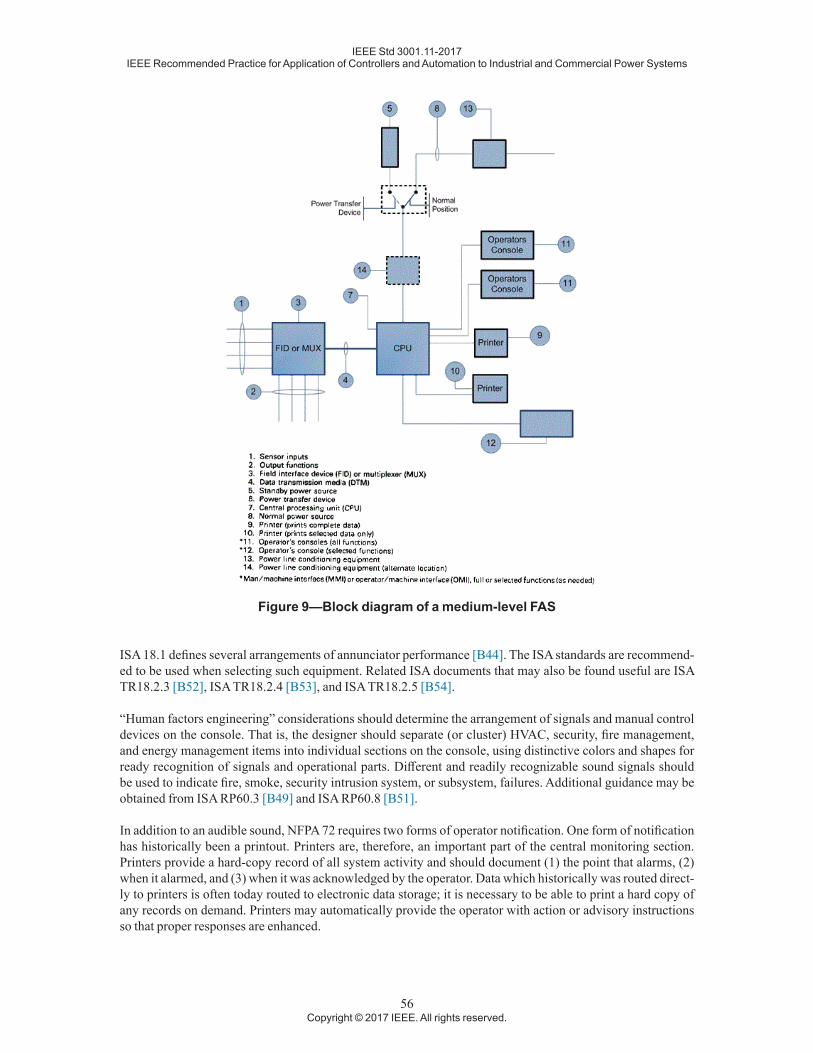
IEEE Std 3001.11-2017IEEE Recommended Practice for Application of Controllers and Automation to Industrial and Commercial Power Systems
56Copyright © 2017 IEEE. All rights reserved.
Figure 9—Block diagram of a medium-level FAS
ISA 18.1 defines several arrangements of annunciator performance [B44]. The ISA standards are recommend-ed to be used when selecting such equipment. Related ISA documents that may also be found useful are ISA TR18.2.3 [B52], ISA TR18.2.4 [B53], and ISA TR18.2.5 [B54].
“Human factors engineering” considerations should determine the arrangement of signals and manual control devices on the console. That is, the designer should separate (or cluster) HVAC, security, fire management, and energy management items into individual sections on the console, using distinctive colors and shapes for ready recognition of signals and operational parts. Different and readily recognizable sound signals should be used to indicate fire, smoke, security intrusion system, or subsystem, failures. Additional guidance may be obtained from ISA RP60.3 [B49] and ISA RP60.8 [B51].
In addition to an audible sound, NFPA 72 requires two forms of operator notification. One form of notification has historically been a printout. Printers are, therefore, an important part of the central monitoring section. Printers provide a hard-copy record of all system activity and should document (1) the point that alarms, (2) when it alarmed, and (3) when it was acknowledged by the operator. Data which historically was routed direct-ly to printers is often today routed to electronic data storage; it is necessary to be able to print a hard copy of any records on demand. Printers may automatically provide the operator with action or advisory instructions so that proper responses are enhanced.

IEEE Std 3001.11-2017IEEE Recommended Practice for Application of Controllers and Automation to Industrial and Commercial Power Systems
57Copyright © 2017 IEEE. All rights reserved.
Several printers are often used in a system. A printer may be designated to handle only one kind of traffic, such as alarm only, security only, HVAC only, logs only, or various combinations of these based upon how the sys-tem will be operated.
Printers are electromechanical devices that require maintenance so that they will remain operational. Many systems are designed with a backup printer that will automatically take over when one of the primary printers is not operating. This prevents important information from being lost. Printers normally assigned to a given function, such as logging, may be programmed as a backup for another machine and will then print out the failed printer’s information as well as its own. Backup magnetic tape, hard drive systems, or other electronic data storage systems, may be used to record all activities entered and alarmed as well.
Many systems require control of all or selected functions from locations other than the primary central moni-toring location. An example may be security monitoring, which is normally controlled from the security office and which may be remote from the main control room. To adequately fill this need, an operator’s terminal and printer(s) can be located in the security office as well as in the control room.
As another example, the building superintendent may want to have access to the system. For the superinten-dent, access to the system should be restricted to only the HVAC or other mechanical systems and perhaps the fire detection and alarm equipment, not to access or control any of the security equipment.
The use of computers allows flexibility in the programming of the system. The main program routine of scan-ning and basic control of the machine is contained in an operating system. Software programs that are devel-oped by a manufacturer and used in many of the same manufacturer’s systems are generally available.
The unique features of each system are accommodated by application programs written specifically for the facility involved. Application software defines the input points, output functions, and the logic of system oper-ations. It is usually entered at the operator’s console.
The system should be designed to allow for the modification of the application software from an operator’s terminal. The cost of the terminal is usually justified by the flexibility and convenience of being able to update the software locally, rather than resorting to the manufacturer’s facilities. For a fire system or other equipment used in an emergency situation, it is desirable to have a generic response to an incoming signal. For this reason, UL does not allow fire systems to have the programming flexibility afforded to noncritical functions.
A large or important facility should have a color video display unit (VDU) with a keyboard as the operator’s terminal. The keyboard has alphanumeric capabilities and dedicated function keys for easy operation. New systems are routinely offering touch screens as the main operator interface, with keyboards relegated to less routine or to data-entry-intensive functions. This type of terminal allows the system to communicate with the operator in the English language and the nomenclature of the facility itself. An alarm may be displayed as “Intrusion Alarm at the West Entrance,” followed by the action that the operator should take, such as “Call Security at extension 537” (operator prompting).
The VDU can also display graphics, such as a floor plan or a schematic of an air-handling system to show the operator exactly which equipment or sensor location is reporting a trouble indication or data readout. Color VDU displays further enhance the system and the functions it can perform.
It should be recognized that color graphic VDU displays and sophisticated features increase the hardware and software costs and the design and delivery time of a FAS. Complex systems may not be justified for many facilities; however, the continuing advances in electronic technologies makes state-of-the-art systems increas-ingly easy to justify economically and operationally.
Annunciators are often used in control rooms or other locations to provide a continuous visual status indica-tion of selected system parameters. These annunciators can be as simple as a grouping of indicator lights with a printed legend for identification. An elaborate annunciator might be a backlit graphic layout of a complete

IEEE Std 3001.11-2017IEEE Recommended Practice for Application of Controllers and Automation to Industrial and Commercial Power Systems
58Copyright © 2017 IEEE. All rights reserved.
building showing its floor plan details and lighting the various automatic detection devices on the floor plan when they are in the alarm mode. However, modern hardware often replaces traditional dedicated annuncia-tors with VDU screens configured as annunciators.
Closed-circuit television (CCTV) allows the operator at the central monitoring location to select and view many remote areas for the purpose of security, access control, or equipment monitoring. Remote cameras can be selected and controlled from the console. CCTV monitors should display date and time data on the screen. Consideration should also be given to acquiring spare monitors. The console designer should limit the number of monitors that an operator should observe to six. This is the largest number that an individual can effectively watch without becoming confused or distracted. Combining other detection devices with CCTV equipment that can cause a camera to be switched to a given monitor and signal the operator is a good alternative. Record-ing of security camera information is also readily available where deemed appropriate.
Systems are available that permit one monitor (VDU) to be automatically sequenced so that it can display information from more than one CCTV camera. In the event of an outage of a CCTV camera, that part of the system can be switched to another camera.
5.5.5 HVAC monitoring and control
5.5.5.1 General
This function includes the automatic monitoring of HVAC equipment. It also provides operating personnel with information on the status of these systems and selected components. Temperature, dewpoint, humidi-ty, pressure, flow rate, and other key operating parameters are continuously “monitored and displayed upon command or when any abnormal or alarm condition occurs.” The information contained in this standard is for general information. For additional information, the ASHRAE series of handbooks [B7], [B8], and [B9], may need to be consulted.
An HVAC facility system also provides for the remote control of necessary functions for the operation of HVAC equipment. From the HMI, fans can be turned on or off, fan speed adjusted, dampers positioned, con-trol valves positioned, pump speed controlled, equipment started and stopped, control points adjusted, and all other functions necessary to properly operate, monitor, and control the mechanical equipment of the HVAC facility systems are programmed for several operating modes. These programs are developed by the ener-gy-management and facility-operating groups. Their data should be incorporated into the software to ensure HVAC operations meet code, occupancy, and energy-conservation needs. These HVAC programs will account for seasonal needs as well as day, night, and holiday occupancy in each of the buildings, or building areas, that comprise the facility. In the case of large areas in which occupancy varies greatly over short time periods, the programs may have to include real-time or hourly control of HVAC components and possibly a major portion of the lighting.
The types of equipment typically supervised by an HVAC control system are:
— Air-handling equipment
— Steam absorption chillers
— Boilers
— Electrically-driven water chillers (compressors, reciprocating or helical screw)
— Air compressors
— Air-cooled condensers
— Dampers
— Evaporators

IEEE Std 3001.11-2017IEEE Recommended Practice for Application of Controllers and Automation to Industrial and Commercial Power Systems
59Copyright © 2017 IEEE. All rights reserved.
— Fans
— Heat pumps
— Heat exchangers
— Liquid tanks
— Pumps
— Refrigerators
— Sump equipment
— Valves
— Control switches (electric/pneumatic; pneumatic/electric)
— Reheat devices
— Cooling towers
— Icemaking equipment
The HVAC conditions and quantities to be monitored or controlled may include:
— Optimized start
— Supply air and water reset
— Temperature dead-band operation
— Enthalpy changeover
— Demand limiting
— Damper position
— Flow rates
— Fuel supply and consumption
— Gas volume
— Humidity/dewpoint
— Real and reactive electric-power demand and consumption
— Line current and voltage(s)
— Liquid level
— Equipment running time
— Equipment wear (revolutions or cycles)
— Leaks and oil spills
— Fan speed
— Degree day heating/cooling
— Power failures (main, auxiliary, control)
— Pressure
— Programmed start/stop operations
— Status of miscellaneous equipment and systems
IEEE Std 3001.11-2017IEEE Recommended Practice for Application of Controllers and Automation to Industrial and Commercial Power Systems
60Copyright © 2017 IEEE. All rights reserved.
— Temperature
— Toxic gases and fluids
— Combustible gases (e.g., methane in sumps and manholes, hydrogen in battery rooms)
— Valve position
— Wind direction
— Wind velocity
— Holiday scheduling
— Run-time reduction
— Night temperature set back
— Central monitoring
— Optimized fresh air usage
— Trend logging
— Pump speed
— Steam flow
— Amount of chilled water generated
— British thermal units (BTUs) of heating or cooling consumed
— Amount of daylight
— Amount of solar energy
— Solar collector tilt angle
— Indoor air environmental quality
— Seasonal changeovers
5.5.5.2 Direct digital control (DDC)
5.5.5.2.1 Introduction
Traditionally, mechanical systems for buildings have been designed with automatic temperature control (ATC) for HVAC systems. Building on this experience plus proven techniques from process control, microcomputer technology offers engineers a powerful tool for the control of HVAC systems. A variety of DDC systems are available from a number of manufacturers.
5.5.5.2.2 Automatic temperature control
In closed-loop control, a sensor provides information about a variable (e.g., temperature) to a controller that actuates a controlled device (e.g., a valve) to obtain a desired setpoint. The output of the controller should op-erate the controlled device to maintain the setpoint (for example, by modulating a chilled-water flow through a coil) even if air or water flow rates or temperatures change. This should happen on a continuous basis and should be fast enough to maintain the setpoint, in which case the controller is said to be operating “in real time.”
The creation of a comfortable environment by heating, cooling, humidification, and other techniques is a real-time process that requires closed-loop control. HVAC systems require many control loops. A typical air-handling unit (AHU) needs at least three (one each for fresh air dampers, heating coil, and cooling coil)

IEEE Std 3001.11-2017IEEE Recommended Practice for Application of Controllers and Automation to Industrial and Commercial Power Systems
61Copyright © 2017 IEEE. All rights reserved.
plus accessory control devices to make them all work in harmony. How these control loops operate has a major effect on the amount of energy used to condition the air.
5.5.5.2.3 Supplying computers to control
DDC systems use digital computers for closed-loop control. This seems the obvious way to apply a computer to a control loop. However, most computers in control applications historically were not applied in this way. Until recently, most computers were principally used as supervisory systems to supervise the operation of an independent control system.
A supervisory computer monitoring the ATC system and capable of resetting the controller setpoint has some very basic limitations, including:
a) The most sophisticated supervisory computer cannot improve the operation of the control loop be-cause the controller is really in command. Any deficiencies or inaccuracies in the controller will al-ways remain in the system.
b) Interfacing the computer to a controller that is frequently a mechanical or electromechanical device is expensive and inaccurate.
c) The computer’s sensor and the actual controller’s sensor may not agree, leading to a good deal of con-fusion or a lack of confidence in one system or the other.
5.5.5.2.4 DDC software
A computer’s power is in its software. When applied to automatic temperature control, properly designed soft-ware offers dramatic benefits, including:
a) Control system design is not “frozen” when a facility is built. Alternative control techniques can be tried at any time, at little additional cost.
b) With software-configured control, all control panels can be identical, which facilitates installation, checkout, and maintenance. One standard DDC computer can control virtually any piece of HVAC equipment.
c) The control system can be upgraded with improved software in the future. No additional equipment or installation will be required.
d) Comfort and operating cost trade-offs are easily made by the flexibility to modify the operating pa-rameters in the control system. Optimum energy savings can be realized without sacrificing occupant comfort.
Flexible software should allow changing not only setpoints, but control strategies as well. Control actions, gains, loop configurations, interlocks, limits, reset schedules, and other parameters are all in software and can be modified by the user at any time without interrupting normal system operations.
With DDC, an operator, via software control, may access all important setpoints and operating strategies. Accuracy is assured by the computer. Control loops can be reconfigured by revising the loop software, with no rewiring of control devices. Reset schedules can be changed just as easily. For example, heating setpoints and strategies can be set in the summer with complete assurance that the DDC system will perform as expected when winter arrives.
5.5.5.2.5 DDC loops
Typically, DDC closed loops consist of sensors and actuators, in addition to digital computers, similar to the controllers. Certain design features should be used to obtain optimum performance from DDC loops. Sensors

IEEE Std 3001.11-2017IEEE Recommended Practice for Application of Controllers and Automation to Industrial and Commercial Power Systems
62Copyright © 2017 IEEE. All rights reserved.
for DDC loops are very important, since the computer relies on their accuracy to provide the precise control that an HVAC system operator needs. A 1 °F change in some temperatures, such as chilled water, can affect en-ergy consumption by a couple of percentage points, so that a control system with even 1 °F of error is not fully controllable in terms of energy use. So as not to waste the precision of the DDC, quality sensors should be used that do not require field calibration, and do not have to be adjusted at all to interface with the DDC computer. Control setpoints are thereby achieved with absolute accuracy under all conditions, at all times.
With the computer performing DDC, the traditional problems of temperature fluctuations and inefficient op-eration can be eliminated. Proportional-integral-derivative (PID) control techniques provide for the fast, re-sponsive operation of controlled devices by reacting to temperature changes in three ways: (1) the difference between setpoint and actual temperature (proportional), (2) how long the difference has persisted (integral), and (3) how fast the actual temperature is changing (derivative). PID saves energy and increases accuracy si-multaneously by eliminating hunting and offset, and by decreasing overshoot and settling time.
All digital computers work with binary (either on or off) information. Since it is necessary to modulate con-trolled devices (e.g., motors that operate dampers or valves), a complicated interface device (digital-to-analog transducer) is often employed. A better method to use, which has been perfected in much more demanding process applications, is pulse-width modulation (PWM). The computer’s binary outputs are directly connect-ed to a modulating device. PWM uses bidirectional (open/close) pulses of varying time duration to position controlled devices exactly as required to satisfy demand. Wide pulses are used for major corrections, such as a change in setpoint or start-up conditions. The pulse width becomes progressively shorter as less correction is required to obtain the desired control setpoint.
5.5.5.2.6 DDC energy management
Many strategies have been developed to effectively manage and save energy in HVAC system operation. DDC systems can be intelligently integrated with temperature control functions in the same computers, in such a way that energy reductions are achieved without compromising the basic temperature control functions. This will also eliminate the need to supplement a conventional ATC system with an add-on energy management system (EMS), which will save equipment, installation, and maintenance costs.
5.5.5.2.7 DDC distributed networks
Implementing DDC in an entire facility with numerous pieces of HVAC equipment can be accomplished with any number of computer and process control systems. Starting with a basic control loop, a system can expand to control an entire facility.
A DDC computer should be capable of handling a number of control loops (four to eight is typical). Acces-sory on/off control and monitoring functions should also be controlled by the same computer. Each computer should be capable of independent operation and be able to perform all essential control functions without be-ing connected to any other computer. This suggests that each separate major piece of HVAC equipment (such as an air handler, boiler, or chiller) has its own DDC computer, in the same way that each would have indepen-dent conventional control panels. These are then tied together in what is called a local area network (LAN) for communications. This results in a truly distributed processing network in which each computer can perform all control functions independently.
Twisted-pair, low-voltage wiring (foil shielded) is an economical choice for the interconnections, although coaxial cable or fiber-optic systems can be used if they are installed in the facility to provide a variety of com-munication services.
Somewhere in this LAN, a “window” is required to allow for human interface with the DDC computers. This is accomplished with a different type of computer, connected to the network at any location, which provides access to the DDC computers. All control setpoints and strategies can be programmed from this access com-puter, and all sensor readings can be monitored.

IEEE Std 3001.11-2017IEEE Recommended Practice for Application of Controllers and Automation to Industrial and Commercial Power Systems
63Copyright © 2017 IEEE. All rights reserved.
5.5.5.2.8 DDC system integrity
A DDC system can be designed for high reliability and for much shorter mean time to repair (MTTR) than a conventional ATC system. The major design requirements are:
a) Independent control computers—In a distributed processing network, these computers assure that the failure of one computer will not adversely affect the operation of other computer systems.
b) Remote data link diagnosis—Allows the computer manufacturer’s factory experts or other special-ized service personnel to dial into the DDC system and troubleshoot control problems.
c) Universal computer replacement—Requires that all control computers be identical, regardless of the HVAC equipment being controlled.
Since the access computer in a distributed network is not capable of any real control, it does not need any spe-cial backup system. Remote data link diagnosis can quickly pinpoint an access computer problem, and repair does not have to be immediate to maintain environmental comfort. All HVAC systems are under the control of the independent DDC computers, which will continue to function normally.
System integrity considerations should also include what happens when a computer fails. A safe condition has to exist when this happens. Therefore, whenever a DDC computer is used, all standard safety devices (i.e., for overload, freeze protection, etc.) should remain in the system with the computer. These are usually very simple devices (certainly less complex than a computer) that have been proven in many years of HVAC system de-sign, and are not rendered obsolete when a computer is used for control of the system.
5.5.6 Energy management
The energy management function of the FAS, which is accomplished primarily through the control of HVAC equipment, is a major item in the reduction of operating costs and the use of energy. This is somewhat different from the energy management systems used in industrial facilities, where large motors are usually the main focus. The FAS will provide the capability to implement the energy management plan. Here, especially, the FAS designer should have close coordination with the energy management engineers. During the preliminary design period, many things happen all at once. Fuel and utility costs change, codes change, techniques change, operating methods change, all in short, and sometimes overlapping, time spans.
The initial decision to implement a single or redundant CPU and to use distributed processing for HVAC should be made early, and backed up with cost and operational data. Thus, the FAS designer and the energy management group should develop a basic plan and get it approved quickly. Once that is done, the space re-quirements and other details can be distributed to all concerned. Selection of sensors and methods for respons-es can then be developed within their own timeframes. Similarly, shutdown alarms and other features can be developed as the design proceeds. To reiterate, the FAS designer and energy management team should develop the basic system early. Standards such as UL 916 [B94] should be required reading before the equipment is selected.
5.5.7 Fire management
5.5.7.1 General
Fire management, as used in this section, encompasses fire alarm systems, the functions of which are detection of fire (manual or automatic) and the sounding of a fire alarm signal for evacuation or other purposes. It may also include smoke control subsystems and more sophisticated occupant notification approaches, as well as fire suppression and other fire safety–related control functions. Fire-management systems should always be considered in the broader context of the facility emergency response plan.

IEEE Std 3001.11-2017IEEE Recommended Practice for Application of Controllers and Automation to Industrial and Commercial Power Systems
64Copyright © 2017 IEEE. All rights reserved.
Fire alarm or management systems are required by code in most commercial facilities. Some industrial fa-cilities which may not be required by code to install these systems choose to install them voluntarily as a prudent decision. It is essential to investigate the code requirements for a voluntary fire alarm system; in some jurisdictions a voluntary system is required to follow the same code design and installation requirements as a mandatory system. The major objectives of these systems are to:
a) Detect a fire as early as possible
b) Notify the fire department
c) Notify the occupants
d) Notify in-house fire wardens (required if system encompasses fire-protection signaling systems, see NFPA 72 [B82])
e) Appropriately control HVAC system to contain fire and smoke (the building code or fire code may have some specific requirements)
f) Use HVAC system to create safe havens within the structure for occupants when evacuation is not practical
g) “Capture” the elevators, according to a preplanned scheme
h) Provide a fire command station to be used by fire fighters as a control center during the emergency
i) Provide an emergency two-way radio or telephone system, or both, for use by fire fighters and in res-cue operations
j) Provide a voice communication system to direct occupants to safety
k) Start fire pumps
l) Initiate fire-suppression systems (e.g., CO2, halon), if installed
m) Supervise and back up all critical fire alarm components to assure their proper operation in an emergency
The basic elements of a simple fire alarm system are initiating devices, control panel, and audible and visual annunciation devices. The other elements that make up a fire-management system are “add-ons” to the basic system.
Initiating devices are the elements that sense the presence of smoke or fire and then inform the system. These devices are either manual or automatic, or both. Manual devices are typically manual pull stations that are strategically located throughout a facility and are intended to be operated by an occupant if he or she discovers a fire. Typically, building or fire codes require that a manual station be located at each legal means of exit (door or stair per floor), and at intervals not to exceed 400 feet along the path of egress.
Automatic devices, of which there are a number of types, sense a characteristic or a result of a fire. Detectors may be mounted in occupied areas or in restricted spaces (e.g., mechanical areas, electrical closets, plenums, hung ceilings, or ventilation ducts). The most common automatic detectors are:
— Thermal detectors that sense heat
— Smoke detectors that sense the visible (i.e., photoelectric) and invisible particles (i.e., ionization) gen-erated by a fire
— Flame detectors that sense the infrared or ultraviolet radiation from a fire
— Rate-of-rise detectors that signal excess temperature rise in a given time period
— Water flow detectors that sense the flow of water in a sprinkler system

IEEE Std 3001.11-2017IEEE Recommended Practice for Application of Controllers and Automation to Industrial and Commercial Power Systems
65Copyright © 2017 IEEE. All rights reserved.
— Tamper devices that signal an abnormal operation
In some large industrial complexes, fire-management systems are combined with combustible and toxic gas-monitoring systems.
Each of the various detector types has subcategories. An engineer designing a fire-management system should be fully familiar with the types and subcategories currently available and their correct application.
Traditionally, 10 or 20 fire alarm detectors have been wired in parallel to constitute a fire alarm zone. When any one of these devices goes into alarm, the fire alarm control panel indicates that there is an alarm in the zone; but the exact device in alarm is not annunciated. The zone isolates a fire location to a particular part of the building, but not the exact location. Device malfunctions that can be caused by the dust contamination of particle ionization and photoelectric detectors can be difficult to locate with this configuration.
Newer fire alarm technologies allow the use of “intelligent” detectors. As many as 100 to 200 input/output de-vices can be wired in parallel on a single twisted pair of conductors. Power and data are transmitted simultane-ously. Each fire alarm device has its own unique address in the system, which allows precise identification of a fire alarm point at the fire alarm control panel. Intelligent fire alarm devices may also have an analog output capability that allows the condition of the particle ionization or photoelectric head to be continuously moni-tored at the fire alarm control panel or central console. This also allows dirty chambers to be detected before a false alarm is generated and the building is inadvertently evacuated.
Annunciating devices are used to notify the occupants that a fire condition exists. In the past, bells, gongs, horns, or a combination of these three, have been the primary method used in fire alarm systems. More recent system designs use electronically generated fire signals that are transmitted by audio amplifiers and speakers. Systems of this design can also be used to broadcast voice messages to give occupants specific instructions, which cannot be given with a bell, gong, or horn. In many jurisdictions, codes require audio systems in high-rise construction. Visual signals are also required by many jurisdictions to signal individuals with impaired hearing. The use of prerecorded messages for directing evacuation or other instructions is controversial. There is the possibility of events that are not predictable and, therefore, not compatible with prerecordings. This is why such systems should be equipped with a microphone, and proper in-house procedures should be devel-oped for its use. In addition to localized annunciating devices, some large industrial facilities additionally provide unit-wide or facility-wide sirens or “air horns” for basic annunciation signaling, including evacuation signaling.
The control panel is the computer of the system, taking the alarm information from the sensors, processing it, and activating the indicating and alarm devices. In addition, this control panel can also initiate other functions that are required in a fire-management system, such as fire department notification, elevator capture, smoke control, etc. The control panel may include a device for recording the time and the location of any fire or smoke indication (a code requirement in some areas). Alternatively, this recorder may be separate and remote from the control panel.
Figure 9 shows a block diagram that describes a medium-level FAS in which the CPU performs the function of the control panel. Many systems use a microprocessor or a minicomputer, which are software-controlled to initiate the desired output functions. Newer systems use addressable/intelligent field devices that can pinpoint the exact location of an emergency situation. Additionally, many systems offer an alarm verification feature that greatly reduces the likelihood of false alarms from smoke detectors. These features should be evaluated on a project-by-project basis.
When an alarm occurs, these systems may be programmed to position dampers automatically and operate fans to create areas of positive and negative pressure to reduce the spread of smoke to other areas and to exhaust smoke from the building. The CPU can also initiate the “capture” of elevators, which sends them to a designat-ed floor for use by fire fighters and authorized personnel.
IEEE Std 3001.11-2017IEEE Recommended Practice for Application of Controllers and Automation to Industrial and Commercial Power Systems
66Copyright © 2017 IEEE. All rights reserved.
Fire-management systems should be as reliable as possible because their function is to protect life and proper-ty. Approval for the equipment’s intended purpose (indicated by a UL label for the United States or ULC label for Canada) should be required when specifying it. Other laboratories or agencies also may be certified to do qualification testing; however, assure that the laboratory or agency is acceptable to the local authority having jurisdiction (AHJ) and to the insurance underwriter. By specifying the UL or ULC listing, there is assurance that the equipment is capable of providing the system operation required by ANSI/NFPA 72. However, the FAS designer is not relieved of responsibility simply by using laboratory listed products. Listed products are only useful when properly applied and thoroughly coordinated. Furthermore, the owner should be notified that scheduled maintenance and tests are required (see NFPA 72 [B82] or ULC S536 [B96] and ULC S537 [B97]). Finally, the responses to signals, alarms, and communications require continual practice, upgrading, and mon-itoring by qualified personnel. The FAS designer may elect to participate in initiating these procedures. (In some jurisdictions, verification of a fire alarm system requires the active paraticipation of a registered engineer as well as the installer.)
The FAS designer should assure that electrical supervision, or monitoring integrity, of signal circuits is provid-ed in accordance with ANSI/NFPA 72. In general, these standards require that a single open or a single ground trouble condition be signaled automatically to, and recorded at, the central supervisory station within 200 s of its occurrence.
5.5.7.2 Life-safety communications
Some systems use prerecorded voice messages to automatically direct the occupants instead of sounding bells and horns (subject to the previously noted limitations). More elaborate versions of these systems use several messages that direct people to different areas, depending upon the location of the fire. For instance, occupants of the fire area may be directed to go up two floors and those below the fire area to go down two floors. Occu-pants of the floor that will be receiving people will be advised, and there may be a general building advisory. Special messages are broadcast to the occupants of captured elevators, advising them of the emergency and instructing them to leave the elevator car when it reaches the designated landing. The messages should be co-ordinated and sequenced properly, so that stairwells do not become overcrowded as people relocate. Usually, the messages for the elevators and fire floor are broadcast first.
In larger public buildings, staged or programmed notification (sometimes referred to as a pre-signal alarm) may be required to the building fire-control staff, local fire department, central supervisory station, mainte-nance staff, and to the public as well as for evacuation.
These systems can also be used to transmit or broadcast special instructions by using a public address feature. In this case, a person in authority, usually from the fire department, will select the areas he or she wishes to address from the console, and his or her voice will be broadcast to those selected areas.
Emergency telephone systems are usually provided to give fire fighters a reliable and private two-way com-munication between the fire command center and each floor. The emergency phones may be permanently installed on the floor and elevators or phone jacks provided, in which case the fire fighter will carry a handset with a phone plug. If phone jacks and portable handsets are used, a highly visible storage area for a number of handsets should be provided at the fire command center.
For convenience, or for code compliance, buildings may include a fire standpipe telephone system. Essential-ly, this is a telephone at each standpipe hose or hose cabinet, at selected valves and at external high-pressure fire department hose connections. When feasible, and in accordance with codes, these telephones may be of the sound-powered type.

IEEE Std 3001.11-2017IEEE Recommended Practice for Application of Controllers and Automation to Industrial and Commercial Power Systems
67Copyright © 2017 IEEE. All rights reserved.
5.5.8 Security
5.5.8.1 Introduction
There are two main aspects to security: monitoring and access control, which are discussed below. This is not to be confused with the security of computer networks, which is not included in the scope of this standard.
5.5.8.2 Security-monitoring systems
Security systems are an essential element in any modern facility. They share a common characteristic in that they continue to expand both in need and in technique. Although every security system should be specifically designed for each individual project, they are all based on the concept of providing safety for the facility occu-pants (employees, contractors, and visitors) and the protection of the contents of the facility. In areas where it is desirable to restrict access to authorized personnel, an access-control system could be utilized. The type and depth of the security system varies with the number of functions performed at the facility. The security level in any one part of the facility may be entirely different from the security level provided in other areas. Banks with generally open or public access will need one type of system. Military installations or offices supporting mil-itary organizations have limited access, and, thus, other security needs. Research facilities, laboratories, and other places where commercial or industrial designs or developments are involved require in-depth security. Stores and normal commercial properties may require limited security precautions. However, if a facility is located in a known high-crime area, the depth of the security system will tend to increase.
The concept of security is to make the system fit the need. Excess security is costly to install and maintain. Minimal protection can, of course, be the most expensive, simply because the owner believes that all neces-sary protection has been provided; but there will probably always be a weak spot in it. Security starts with protection at the perimeter of the property. A chain-link fence may be used to prevent a casual walk-in by neighborhood youngsters and will identify a specific property line. More protection at this fence can be pro-vided by using outdoor perimeter detection devices that will detect intruders crossing the property. Infrared light beams, microwave, E-field, or covered and buried line detectors are just a few of the possibilities. At the perimeter of the building, magnetic switches can be used to monitor perimeter doors and other movable openings. Window foil, traps, pressure mats, and infrared devices may be used to protect other areas inside the building perimeter. Motion, audio, capacitance, infrared light, and vibration-detection devices may be used to protect areas and objects within the facility.
Supervision of the data transmission medium that extends to the sensors is important in a security system, just as it is in a fire alarm application. In the case of fire, a break in a wire is handled as a trouble condition. However, in a security application, the loss of supervisory current may be caused by an intruder attempting to compromise (defeat) the alarm system, and it should be treated as an alarm, not as a trouble indication. A ±50% change in line current should indicate an alarm meeting UL Grade A requirements. This is adequate for most general security applications.
Communicating alarms in high-security areas should be by two channels. The telephone system may be used as the primary channel to the UL-listed central monitoring facility, and this should be backed up by a radio link.
When high security is required, random digital or high-speed digital interrogation and response are techniques designed to render the circuits that are most difficult to compromise. These techniques usually satisfy UL Grade AA requirements. CCTV can be used in manned operations to allow a single guard to observe many areas. Cameras can be controlled from the central monitoring location to view a larger area. Cameras are available that operate with very low ambient light levels (i.e., starlight) and still produce a satisfactory image. It should be remembered that the security office cannot watch a television continuously; thus the CCTV is an adjunct subsystem for specific and intermittent needs. Individual applications of CCTV cameras may require certain optional equipment or auxiliaries, such as:

IEEE Std 3001.11-2017IEEE Recommended Practice for Application of Controllers and Automation to Industrial and Commercial Power Systems
68Copyright © 2017 IEEE. All rights reserved.
a) Fixed focus camera.
b) Remotely controlled pan, tilt, and zoom lens functions.
c) Outdoor camera enclosures that may include heaters, windshield wipers, or sun visors. In some in-stances, pan and tilt limiters may be required to avoid directly arming the lens into the sun.
Motion detection or other sensing technlogoies can be an integral part of a television system that is silently viewing an area. When motion is detected in an area viewed by a camera, that camera will be automatically switched on to a monitor for viewing, possibly using light or sound to attract the attention of the security offi-cer. The trespass can be captured on videotape or hard drive.
It is obvious that there are special operational considerations, as well as technical design problems, in the development of a CCTV installation plan. For the FAS designer, it is often advisable to obtain specialized sup-port services to assist in the design of, and user coordination with, the CCTV system.
5.5.8.3 Access control
Another security system allows access to a facility without the need for locks and keys. In many instances, keys and locks are too cumbersome and expensive a method to secure an area or building. Keys are lost or proliferate when people entrusted with them have copies made or fail to return them. Cylinder pins wear, and weather also affects conventional locks. A modern and very popular approach has been the card reader. A plastic card, similar to a bank or credit card, is encoded with a hard-to-reproduce cipher. Several different tech-niques for encoding are in use, such as magnetic stripe or bits, capacitance, photoelectric, and radio frequency. The encoded card is placed in (or near) a fixed card reader at a point of entry, which determines if the card is valid. If the card is valid for that door, time, and day, it will release the doorlock and allow entry. Systems that require entering a secret number, unique to each card, on a keyboard as well as inserting the card in the reader add another level of security. Other security systems are biological in nature, requiring a hand, eye, finger, or voice to be analyzed and matched to the database. Unauthorized entry attempts by individuals are processed as an alarm and indicated on the operator’s terminal, other signal or display, and alarm printers. The system may also be instructed to record each entry transaction on a printer. The use of card-access systems is increasing, and new innovative ideas, such as parking garage access; time, attendance, and resource control; and tracking badgeholders on a real-time basis throughout a facility, are being introduced. A properly designed card-access system can be used to replace guards in low-traffic situations. The FAS designer is advised to research the available market to be assured that he or she is specifying and obtaining a state-of-the-art access-control sys-tem, consistent with the functional requirements which have been justified for the facility.
5.5.9 Transportation and traffic
Transportation and traffic control equipment that may require control and monitoring include the following:
a) Driveway and roadway traffic control
b) Loading dock traffic control
c) Elevator status
d) Escalator status
e) Moving walk status
f) Parking access control
Whether these are to be programmed, manually controlled, sensor controlled, or simply monitored are matters for coordination with the discipline that has the design or operating responsibility. These must always be coor-dinated with the facility emergency action plan.

IEEE Std 3001.11-2017IEEE Recommended Practice for Application of Controllers and Automation to Industrial and Commercial Power Systems
69Copyright © 2017 IEEE. All rights reserved.
There are obvious precautions, such as:
— No remote control over escalators where starting or stopping remotely has the inherent possibility of danger to riders.
— No possibility of a remote shutdown of an emergency system or safety device.
— No countermanding of signals or directions by facility operators, unless a local authority requires emergency personnel to have that ability.
— A procedure for advising police, fire fighters, or emergency medical personnel where to (or not to) en-ter the facility.
5.5.10 Pollution and hazardous waste management
Monitoring and control of functions associated with pollution and hazardous wastes may be integrated into the FAS. Functions to consider including are monitoring of air quality (particulate level); monitoring and control of baghouse and scrubber equipment, such as pressure drop across air filters; monitoring of effluent water quality (e.g., percentage of dissolved oxygen); leak detection in hazardous liquid holding tanks; and monitor-ing of carbon monoxide in garages.
5.5.11 Electric power-distribution system management
5.5.11.1 Introduction
Included in this category are the monitoring and control of lighting; normal, standby, and emergency power sources; power conditioning equipment; uninterruptible power supply (UPS) systems; and electric power-dis-tribution systems.
5.5.11.2 Lighting automation systems
The ordinary control of lighting is performed by one or more of the following methods:
a) Local manual switches
b) Switches or circuit breakers in panelboards
c) Time clock operation of contactors and relays
d) Daylight sensors operating through relays and contactors
e) Illuminance sensors controlling lamp light output through ballast dimming-control circuitry
The variety of lighting controls available for non-theatrical usage has increased greatly in recent years. Many systems are stand-alone, with a variety of computer interfaces available. The FAS offers the opportunity to provide for the programmed control of lighting as a part of the energy management system. That is, programs are commercially available for the timed control of various lighting needs, such as:
— Continuous light in stairwells and exit pathways
— Timed control of indoor, general light
— Sensor control of light adjacent to window areas
— Timed or light sensor control of light in vehicle parking areas and garage decks
— Continuous nighttime lighting for security
— Timed or sensor control of light used for advertising or display

IEEE Std 3001.11-2017IEEE Recommended Practice for Application of Controllers and Automation to Industrial and Commercial Power Systems
70Copyright © 2017 IEEE. All rights reserved.
— Notification of manual turning on or leaving on of lights during off-hours
— The user is cautioned that manual over-ride provision is usually necessary for some daylight or occu-pancy sensor controlled lighting circuits, for safety and operability reasons.
5.5.11.3 Normal and emergency power sources
Monitoring and control functions that are associated with power sources may include the following (refer to NFPA 110 [B83] and NFPA 111 [B84]):
a) Circuit breaker open/closed status
b) Circuit breaker open/close command
c) Static switch source 1–source 2 command/status
d) Automatic transfer switch normal source command/status
e) Automatic transfer switch emergency source command/status
f) Engine or turbine low-lube-oil-pressure alarm
g) Engine- or turbine-overcranking alarm
h) Engine or turbine air-shutdown damper alarm
i) Generator on/off status
j) Engine or turbine high-temperature alarms
k) Generator overtemperature alarms
l) Frequency of commercial supply and generator
m) Kilowatts, kilovars, and voltage
n) Power failure of supply or of power subsystems; operation of protective relaying
5.5.11.4 Uninterruptible power supply (UPS) systems
Additional monitoring and control functions that are associated with UPS systems may include the following (refer to ANSI/IEEE Std 944 [B3], now withdrawn):
a) Loss of synchronization (inverter not synchronized to alternate ac source, or alternate ac source unavailable)
b) Low inverter voltage
c) Protective device actuation
d) DC bus undervoltage
e) Overload
f) Reverse transfer (load is supplied by the alternate ac source)
g) Cooling trouble
h) Alternate ac source trouble
i) DC operation
j) AC input disconnect device position
k) DC input disconnect device position
IEEE Std 3001.11-2017IEEE Recommended Practice for Application of Controllers and Automation to Industrial and Commercial Power Systems
71Copyright © 2017 IEEE. All rights reserved.
l) Static transfer switch position
m) Output disconnect device position
n) Maintenance bypass available
o) Critical load on maintenance bypass
p) Battery charging rate (float/equalize)
q) Redundant power converter module unavailable
5.5.11.5 Electric-distribution system control
The automation of electric-distribution systems may be accomplished through the control and monitoring of power circuit breakers. Alternatives include electrically-operated circuit breakers and fusible switches, shunt tripping of manually-operated circuit breakers, and electrical contactor control. A variety of automation op-tions exist. The developing trend to operate breakers “out of the line of fire,” that is, away from the face of the equipment, coupled with the availability of a wide variety of solid-state control equipment from most manu-facturers, is making the installation of touch-screen HMI panels near, but not immediately adjacent to, elec-trical switchgear more common for many industrial facilities. Safety, including arc-flash concerns, is moving some owners to use networked power systems protective relays to implement protection schemes which, until recently, were impractical for most users. This is a topic which has been and will continue to be explored with-in IEEE Industry Applications and IEEE Power and Energy conference papers and recommendations. The primary papers and standards are not building related, they are either process industry or power transmission utility related, but the techniques can also be scaled down to commercial buildings, and certainly applied to commercial type buildings which are part of an industrial or institutional complex.
5.5.12 Mechanical utilities
The FAS may be called upon to monitor and control a number of mechanical systems, other than HVAC, including: water supply and distribution, sanitary and storm sewers, compressed air supply and distribution, de-ionized water, natural gas, and liquid fuel storage and supply. Functions and conditions may include:
a) Pressure (water, air)
b) Level (water, sewage, fuel)
c) Water acidity/alkaline concentration level
d) Pump status
e) Valve position
The monitoring and control of individual mechanical systems may require overall supervision by the CPU, rather than distributed control at each satellite FID location. An example where CPU supervision is required is in the implementation of electrical demand limiting.
5.5.13 Communications
5.5.13.1 Maintenance
A telephone jack or instrument or internet connection, if not both, should be installed at each remote FID and MUX location to facilitate both initial system checkout and point calibration as well as subsequent trouble-shooting efforts. In some situations, wireless systems are supplanting the requirement for wired connections, but the functionality should be provided nonetheless.
IEEE Std 3001.11-2017IEEE Recommended Practice for Application of Controllers and Automation to Industrial and Commercial Power Systems
72Copyright © 2017 IEEE. All rights reserved.
5.5.13.2 Central supervisory station
A central supervisory station is an off-premises office, usually operated by an independent private company, for performing supervisory functions. Fire alarm and security operations are most often performed by these companies; however, many of the other alarm and control functions described in this standard can also be performed by them. When security, life safety, and fire services are involved, the approval, authorization, and certification of these companies should be obtained from the authorities having jurisdiction over them (e.g., fire and police departments) and from insurance underwriters.
The central supervisory station staff, as directed, will notify fire and police departments and other municipal agencies, building staff, listed company supervisory staff (paged, at home or at work), or perform such other activity as is prescribed whenever appropriate signals or levels are indicated. The central supervisory station may replace local building operations fully or partially for all or some of the FAS supervisory functions. During off-hours, the central supervisory station may be responsible for all supervisory functions.
Connections between the facility and the central supervisory station are achieved through a supervised tele-phone line. Provisions should be made for the connection of the central supervisory station to the facility’s equipment, usually an auxiliary connection to the central console computer when one exists. For smaller facil-ities, it may be connected by an electronic interface.
5.5.14 Miscellaneous systems
5.5.14.1 Introduction
The functional categories of monitoring and control points that were already discussed are not intended to lim-it the range of options available to the FAS designer. Any number of facility process and support systems, from material handling and conveying to pneumatic tube, may be integrated into the FAS design.
5.5.15 Computerized maintenance management system (CMMS)
5.5.15.1 Introduction
The CMMS should include subsystems, as follows:
a) Equipment records
b) Inventory and purchasing
c) Work order planning
d) Work order implementation
e) Preventive maintenance
f) Downtime information
5.5.15.2 Equipment records subsystem
Equipment information includes specifications, ratings, spare parts, cross-referencing, manufacturer-of-re-cord, installing contractor-of-record, maintenance contractor-of-record, model number, installation date, and other history.
Cross-referencing capabilities should provide reference to a piece of equipment by several common criteria.
5.5.15.3 Inventory and purchasing subsystems
An inventory subsystem should provide:
IEEE Std 3001.11-2017IEEE Recommended Practice for Application of Controllers and Automation to Industrial and Commercial Power Systems
73Copyright © 2017 IEEE. All rights reserved.
— Multiple warehousing or storage locations per item
— Stock item usage information
— Economic order quantity calculation methodology
— Minimum and maximum order quantity calculation methodology
— Reporting a notification to reorder specific items
— Cross-referencing
The cross-referencing features shall enable the user to:
a) Locate stock items by manufacturer
b) Locate stock items by manufacturer part number
c) Locate stock items by generic name
5.5.15.4 Work order planning subsystem
A work order planning subsystem should provide the functions that help plan the work to be performed. The primary objectives of work order planning are:
a) To provide an efficient means of requesting and assigning work to be done by maintenance personnel
b) To provide an efficient means to requisition materials for the work order
c) To provide a method of transmitting written instructions on how work is to be done
d) To provide estimates and accumulate actual maintenance costs
e) To provide the information that is necessary for the preparation of management reports
5.5.15.5 Work order subsystem
A work order subsystem should provide the mechanism for the entry, updating, and monitoring of work orders. The primary objectives of a work order subsystem are:
a) To provide for the entry and updating of work orders
b) To provide for various inquiries on work orders
c) To provide a method of reporting costs to the work order
d) To provide a means to capture historical data upon completion of the work order
The work order subsystem should provide current work orders in the backlog according to specific criteria, including by a single cross-referencing item or by multiple items.
The cross-referencing procedure should allow:
1) Calling up the work order backlog of an individual craftsman or by a crew
2) Same as in item 1), except only high-priority work orders would be called up
3) Calling up the work order backlog on a specific piece of equipment or system
4) Calling up all work orders backlogged due to lack of parts or tools
IEEE Std 3001.11-2017IEEE Recommended Practice for Application of Controllers and Automation to Industrial and Commercial Power Systems
74Copyright © 2017 IEEE. All rights reserved.
5) Calling up all work orders issued to a specific subcontractor or maintenance contractor
The work order subsystem should be capable of producing a maintenance schedule for each craftsman or crew.
5.5.15.6 Preventive maintenance subsystem
The preventive maintenance subsystem should identify all preventive maintenance activities within the facili-ty for each major piece of equipment and system listed.
Preventive maintenance scheduling should utilize appropriate combinations of manually entered recommend-ed maintenance intervals dependent upon calendar time (hour, day, month, quarter, year) and equipment or system-operating parameters.
System operating parameters are defined as:
a) Running hour meters
b) Clock hour meters
c) Flow meters (ft3/second, gallons/hour, etc.)
d) Consumption meters (kWh, gallons, etc.)
e) Load meters (percent of full load)
f) Cycle meters (on/off cycles)
g) Vibrations
h) Noise
i) Temperature
j) Displacement
k) Velocity
l) Combinations of the above in “dynamic predicted maintenance,” “signature analysis,” etc.
m) Other parameters
The preventive maintenance subsystem should be designed to minimize labor demands by scheduling main-tenance only as required by the system operating parameter and in conformance with manufacturers’ recom-mendations and generally accepted standards for maintenance.
The schedules should be available by crew or facility location or by major equipment systems. Summaries should display labor by craft, by facility locations, by crew, or in the entire facility.
5.5.15.7 Downtime information subsystem
The downtime information subsystem should provide downtime tracking for critical pieces of equipment within the facility. Summaries of outages and equipment availability should be instantly retrievable in order to isolate problem areas and evaluate the causes of downtime.
The downtime information subsystem should also provide for major overhaul or renovation work. The system should be capable of describing the step-by-step tasks, the scope of the work, and the craft requirements and weekly labor summaries by craft for labor forecasting.

IEEE Std 3001.11-2017IEEE Recommended Practice for Application of Controllers and Automation to Industrial and Commercial Power Systems
75Copyright © 2017 IEEE. All rights reserved.
5.5.16 FAS design and installation
5.5.16.1 Introduction
The design of a FAS requires the coordinated efforts of a number of engineering disciplines including mechan-ical, electrical, and instrumentation and controls engineers. The following paragraphs address salient points about the design and installation of a FAS.
5.5.16.2 FAS system specification
A system specification is essential for all, or almost all, FASs. It spells out the requirements of the system, at an early stage and in sufficient detail for evaluation; in-house review; and preliminary discussions with approval authorities, consultants, and suppliers. Later, it will be developed to a point where it can be used for detailed design, incorporated into the technical specifications of a purchase (or lease) contract, or into furnish-and-in-stall provisions of a contract. The system specification contains the following features:
a) A list of all systems to be covered by the FAS, together with all functional requirements. Later in the design stage, these requirements will be detailed as to specific equipment, setpoint ranges, physical constraints, installation requirements, and the factors listed in this standard regarding system features.
b) Approval and review procedures. All of the operational, security, and general staff should approve the proposed installation at some point.
c) In-house and, when appropriate, consultant review by:
1) Owner’s staff, if designed by others
2) Safety staff
3) Fire-prevention staff
4) Security staff
5) Law department (contract, claims)
6) Architects (location and finishes of alarm, display, and other devices)
7) Operational staff
8) Maintenance staff
9) Insurance staff
10) Construction and inspection staff
11) Jurisdictional approval authorities, fire, police, code, and insurance underwriters
d) Content and format of displays and hard-copy output to be developed in conjunction with all affected staff; general layout and characteristics of input and display devices; specification of the manner of operator input of variable system parameters, added devices, or system data as distinct from software modifications.
e) Backup, emergency, and contingency modes of operation.
5.5.16.3 Selection of data transmission medium (DTM)
The FAS designer should select one of several DTMs in order to allow the central components to communicate with remotely-located equipment. An economical solution often used to provide connectivity for a complex of buildings is existing telephone pairs. Other DTM to consider are:
— Shielded or unshielded twisted pairs

IEEE Std 3001.11-2017IEEE Recommended Practice for Application of Controllers and Automation to Industrial and Commercial Power Systems
76Copyright © 2017 IEEE. All rights reserved.
— Fiber-optic cable
— Coaxial cable
— Power line carrier over existing wiring
— Two-way radio
— Cellular telephone
— Point-to-point microwave
— Infrared light transmission
— Laser light transmission
Based on the owner’s requirements, the designer may need to evaluate the reliability and speed versus first cost and life-cycle cost of the potential DTM.
5.5.16.4 Interfacing to existing equipment or equipment provided by other disciplines
One method that is available to provide a single identifiable interface point is the provision of a data terminal cabinet (DTC) in each mechanical equipment room or near each major system that is monitored or controlled. The DTC contains double-sided terminal strips, with one side connected to field wiring from instrumentation and controls, and the other side connected to a FID or MUX.
5.5.16.5 Procurement documents
In preparing plans and specifications for a FAS, the designer should include a detailed point list of all func-tions monitored and controlled that includes the range of values expected for analog points. In general, per-formance-type specifications are preferred for hardware in order to allow for differences in manufacturers’ equipment. In specifying system software, a method for entering user data, such as adding and deleting points, changing temperature limits and start/stop times; the capability for user created programming; and the capa-bility to design statements for DDC loops should be required.
5.5.16.6 Installation
Prior to equipment purchase, detailed construction drawings that show the connections to existing equipment, equipment locations, and all conduit runs should be provided. During the construction period, periodic tours of the job site should be made by the designer. Care should be exercised when making modifications to existing equipment so as not to defeat existing safety interlocks.
5.5.16.7 Testing
In general, two stages of testing are desired: factory tests and site-acceptance tests. The factory-test setup should include the CPU and all peripherals, representative FIDs and MUXes, and DTMs of each type to be provided in the system. Site acceptance testing should verify the operation of all points in the system and demonstrate that all analog inputs and limit alarms are within specified tolerances. Verification of system operation in failure modes (e.g., loss of power at a FID, loss of CPU operation) should be demonstrated. In ad-dition, if the criticality of the FAS warrants it, an endurance test that continues for two weeks may be requested in order to demonstrate overall system reliability.
5.5.16.8 Warranty
A warranty period, which starts after system acceptance, should last at least one year. The warranty covers the repair of equipment and software that fails during the designated period, but does not include regular preven-tive maintenance.

IEEE Std 3001.11-2017IEEE Recommended Practice for Application of Controllers and Automation to Industrial and Commercial Power Systems
77Copyright © 2017 IEEE. All rights reserved.
5.5.16.9 Software
Commonly available software, some or all of which may be specified dependent on the size and complexity of the FAS, includes:
a) Alarm priorities
b) Alarm inhibitions
c) Analog alarms
d) Integrations, e.g., energy consumption
e) Totalization, e.g., summation of motor run times
f) Time switching, including optimizing start and multiple-channel control
g) Enthalphy control of HVAC systems
h) Event initiated sequences, e.g., an alarm that initiates a specific sequence of operations
i) Load shedding
j) Load cycling
k) Restart after power failure—prevents electrical overload on restart
l) Process control, i.e., the use of system remote stations as the controllers for individual loops
m) Optimum damper control (free-cooling cycle)
n) Security, e.g., patrol tours and card access
o) Interlocking, i.e., the use of software instead of relays and timers, etc.
p) Fire, i.e., alarms and specific event initiated sequences
q) Maintenance management, i.e., the use of stored and real-time data to produce a work schedule for maintenance and servicing
r) Historical data logging
5.5.16.10 System documentation
The following documents should be submitted by the FAS contractor prior to the acceptance of the system:
a) As-built drawings, including system block diagrams, central control equipment installation, schemat-ic diagrams and physical layouts for FIDs and MUXes, and wiring diagrams of sensors and controls
b) Test plan and step-by-step test procedures for factory, site verification, and endurance tests
c) Operation and maintenance manuals covering:
1) Functional design
2) Hardware
3) Software
4) Operator’s instructions
5) Maintenance procedures
d) Training program, including lesson plans and videotape training for both system operators and main-tenance personnel

IEEE Std 3001.11-2017IEEE Recommended Practice for Application of Controllers and Automation to Industrial and Commercial Power Systems
78Copyright © 2017 IEEE. All rights reserved.
5.5.16.11 Programming
Most systems will be purchased with software already installed. This is the quickest and most reliable meth-od of obtaining tested software that also meets the requirements of approval agencies. There are instances in which in-house programming will be undertaken, usually for specialized subsystems in a distributed-type sys-tem (e.g., parking control system). In other instances, there may be a requirement that the in-house staff have the capability of modifying the existing system. Under these circumstances, it is important that the following items be included in system specifications:
a) The equipment should meet the programming needs of in-house staff. For example, an imbedded com-puter (special design) may not be practical, whereas a separate standard computer using a standard op-erating system and a specified higher-level language (e.g., Basic, C, Pascal) might be suitable for the programming staff. When consultants may be called upon to perform initial and future programming, the same constraints hold true. The program should be furnished in a format that is usable by in-house staff or consultants; the object (machine-usable codes) assembly format is most often unusable by this staff.
b) The software development should be checked frequently with the programming staff. Too often, the system specifications are written so loosely or so misunderstood that unsatisfactory programming is noticed only on final testing.
c) The availability of appropriate staff should be assured before undertaking the programming. Often, the in-house programming staff will be unfamiliar with real-time programming; the safety redundan-cies, reliabilities, and legal requirements of life-safety systems; and with the equipment being fur-nished. The costs associated with in-house programming often far exceed the cost of the computer and console equipment. If programming changes are required, the time for staff to familiarize themselves with the software may be extensive, especially if individuals not associated with the original installa-tion are assigned to this task.
5.5.16.12 Physical installation
There are installation procedures that enhance the reliability and security aspects of the FAS, including:
a) Equipment should be located in areas where it will be physically and environmentally protected. While some equipment is suitable for mounting in relatively unprotected non–air-conditioned areas (e.g., some programmable controllers), most are not. Most standard FAS equipment should be installed in air-conditioned rooms where the temperature, dewpoint, and air cleanliness are controlled. Conduit entrances into boxes should be sealed against the flow of air between areas (often an NEC require-ment). Terminal and equipment boxes should be properly gasketed and sealed. The enclosure protec-tion should be the appropriate NEMA classification (e.g., water-resistant, dust-tight). The equipment should not be located in basements or mechanical areas if flooding is a possibility. In particular, where there is more than one control point, the failure of equipment at one location should not disable backup equipment.
b) The equipment should not, as far as is practical, be located where the hazard that it is protecting against will disable the system. The DTM should be located in fire- and vandal-resistant areas. FAS wiring should normally be kept separate from other control wiring. Local power supplies should be sepa-rated from normal outlet wiring, as required, to meet reliability requirements. A completely separate conduit system provides a high degree of protection. In some instances, items such as terminal boxes might be lockable to prevent accidental or deliberate tampering. Except when security requirements militate against it, FAS wiring and enclosures should be clearly labeled. Codes and regulations usually require that exposed wiring be suitably protected and/or be of flame-resistant, high-temperature con-struction. (Refer to the NEC, Article 725 for the appropriate cable types.) Some codes either require or recommend various wiring fire survival requirements; two hours is not uncommon for many commer-cial buildings.

IEEE Std 3001.11-2017IEEE Recommended Practice for Application of Controllers and Automation to Industrial and Commercial Power Systems
79Copyright © 2017 IEEE. All rights reserved.
c) The power supplies to equipment should be of high quality, relatively free from noise, and, where re-quired, use filtering, transformer isolation, and packaged power conditioners or converters to enhance power quality. UPS systems are effective in power improvement only to the extent that they contain these features. While twisted telephone pairs provide a high degree of immunity to certain types of interference, shielded or double-shielded cables provide much greater immunity. Perhaps the highest degree of immunity is provided by steel conduits and steel enclosures, which do have excellent mag-netic shielding. Fiber-optic cable is immune to EMI, and, where available, photo-optical coupling for terminals provides excellent protection against common-mode noise.
5.5.16.13 Backup modes
Fortunately, computer installations are becoming increasingly reliable; however, failures do occur, and routine maintenance is required. Software modifications or system reconfiguration may require outages or extended testing, particularly during the commissioning period (which may also be a concurrent operating period). The overall reliability of any system is affected by the number of fallback positions that are available in the event of the outage of any part of the system. Standby power and uninterruptible power supplies have been previously discussed. Hot-swappable component capabilities minimize the time required to restore full system function-ality. Software, configuraiton, and setpoint backup should also be provided. The following are possible modes of backup:
a) Control console. The control console may be designed so that the loss of one subsystem does not affect other subsystems. Redundant modules, such as multiplexers, may be automatically switched on or manually replaced. Software provisions may permit limited system control by using keyboard input in the event of control panel switch failure. When there is more than one console, the obvious choice is to use one of the alternate operating positions, and the system design should be developed to accom-modate this. When one of the alternate positions does not normally have all of the system functions available, all should be made available when it is in backup mode. The transfer should be made so that all interconnections that might prevent operation in the backup mode are cleared. (Just switching off the power to a defective console may not be sufficient.)
b) Distributed computers. In the event of control console outage, the possibility of operating from dis-tributed consoles has been discussed. Of course, control features should be provided if this is to be a possibility.
c) Field interface devices (FIDs). If control features (perhaps plug-in and portable) are available, another stage of backup can be located at the FID.
d) Local control. The most fundamental system backup is manual operation or control of system devices at the device. This has the great disadvantage of circumventing system control logic and might even involve some loss of safety interlock features.
In any backup mode, the loss of telemetering functions is an important consideration.
5.5.17 Training
Unless maintenance and programming are to be performed exclusively under contract, training will be re-quired. It is important that the training program for staff be spelled out completely in the original contract for equipment purchase; otherwise, separate charges will be encountered and the training will be at the con-venience of the manufacturer. It is important that training for complex systems, particularly those that are nonstandard, be given at around the time of system commissioning because all the personnel responsible for system design and programming may not be available at a later date. Even if maintenance and operation are performed under contract, it is advisable, at a minimum, for key owner personnel responsible for the system to have overview training for the system.
IEEE Std 3001.11-2017IEEE Recommended Practice for Application of Controllers and Automation to Industrial and Commercial Power Systems
80Copyright © 2017 IEEE. All rights reserved.
The contract should specify the number of people to be trained, the level of training for each group of people, and the length of time training is required. As part of the proposals submitted by the contractor, a complete outline of the training programs, the approximate times they are to be given, and the detailed material to be covered should be spelled out and approved by the user. There have been instances where training for com-puter systems was largely wasted because the training was very general in nature (emphasizing such general subjects as binary notation), given on different equipment from what was to be purchased, or provided on incomplete, nondebugged systems.
Except for simpler systems, training programs may be conducted at the factory or at the place of initial setup during the test period. Here, the staff will be away from their normal duties and can concentrate on studying the system. The operators courses are usually fairly brief, but should also be attended by programming and main-tenance personnel. For extensive systems, system-maintenance personnel training may take many weeks. When budgeting the purchase of the system, the cost of living expenses and supplemental training expenses should be included, as well as travel expenses.
On-site training is required during the commissioning period. Here, the emphasis is primarily on hands-on training of the operators. The training should include simulated failures and the performance of all routines required (including any special operating system dumps); the opportunity should be taken to go through the complete range of operations with the operators. Maintenance personnel should be given the opportunity to work with the contractor’s staff as the system is put into service, even though there is little opportunity to per-form maintenance since the contractor is primarily interested in getting the system online and accepted.
Videotaped training programs are essential for recurrent training of facility personnel. These videotapes should be maintained within the facility for casual and formal reviews as needed. Training programs should be updated as the hardware and software are modified throughout the life of the facility.
When establishing the curriculum for on-site training, if it is not included in the contract, relatively high train-ing personnel costs (including travel and living expenses) can be encountered.
5.5.18 Maintenance and operation
5.5.18.1 Introduction
Maintenance and operation may be performed by in-house personnel or by contractors. Because many new systems are microprocessor types, there is a tendency by some toward in-house maintenance that is supple-mented by contract or manufacturer maintenance for serious problems. There is a general trend by many large organizations to outsource all maintenance and operations functions possible, both in commercial and industrial facilities. The designer should discuss these options with the owner, and assist in determining the appropriate course of action for a given installation at the time of design.
In any event, the effectiveness of in-house maintenance is a direct function of the training and skills of the staff. A technician or electrician will normally require special training to maintain these systems at any level. Even though a system may remain operational with relatively poor maintenance, it can be expected to degrade over a period of time to a level where it will be totally unreliable. Coordination of the maintenance programs covering the availability of competent personnel during off-hours and coordination with contract personnel is essential. A careful delegation of work responsibilities to the various classes of technicians will avoid the problem of a technician damaging equipment or aggravating an outage when attempting maintenance beyond his or her capability.
5.5.18.2 Maintenance approaches
The peripheral devices that are used for sensing, controlling, and monitoring electromechanical systems may be electrical, electronic, or electronic/pneumatic. These are usually maintained on a first-level basis by the as-signed electrical, mechanical, or specialized journeyman. The level of maintenance permitted should be com-mensurate with the journeyman’s qualifications. For example, in the “off-shift,” a general “mechanic” may be
IEEE Std 3001.11-2017IEEE Recommended Practice for Application of Controllers and Automation to Industrial and Commercial Power Systems
81Copyright © 2017 IEEE. All rights reserved.
the only individual available and may be limited to functions as simple as manually operating equipment in the event of a failure.
Specialized sensing and electronic-control equipment that may be located at the controlled or monitored de-vices may require more skilled maintenance. These devices generally incorporate a number of integrated cir-cuits that should be field diagnosed, replaced on a modular basis, and returned to a central repair location or to a special service shop. The technicians performing this latter function, either electricians, mechanics, or instrument repairmen, will require specialized training.
The remote control station, also known as a field interface device (FID), slave station, data-gathering panel (DGP), or remote terminal unit (RTU), which consists of relatively sophisticated electronic equipment, can be maintained by specialists or by specially trained building-maintenance staff (often electricians). These ter-minals are usually arranged in a modular fashion so that cards, relays, and other devices can be replaced with identical elements following a prescribed maintenance procedure. Detailed work on the individual cards or other elements is usually avoided at the site. Rather, these elements are returned to a “central shop” or to a manufacturer’s repair facility. Defective power supplies may be replaced as units by electrical staff.
The control distribution (data transmission) system that interconnects the main control rooms with remote ter-minals may consist of twisted pairs of telephone wires, shielded twisted pairs, or bundles of twisted pairs, co-axial cable, or fiber-optic cable. Typically, these could be maintained by qualified, trained electricians, unless delegated to specialized crews. The splicing and termination of fiber-optic cable usually requires specialized training, and the testing of coaxial cable will require special test equipment that may require the services of an electronic technician.
At the central control room, the distribution system will usually terminate in a special cabinet, which can also be maintained by qualified electricians. From here, interconnections are made to multiplex systems, comput-ers, printers, mass storage units, interfacing, and other control devices. These units are often maintained by special maintenance personnel from the manufacturer or from an organization specializing in computer main-tenance. The peripheral devices for output, display, and mass storage (e.g., floppy disks, hard disks, monitors, printers) are usually maintained by the computer system–maintenance contractor. Some owners prefer to have only the most complicated equipment maintained by contractors and the less complicated modular equipment maintained by a specially trained in-house staff.
5.5.18.3 Operations
The system operator keeps the system running on a continuous basis by performing a prescribed set of rou-tines, responding to alarms, keeping the system loaded with tapes or disks, keeping the printers in operation, and generally overseeing the inputs and outputs to and from the system. For larger systems, this may involve several levels of operation, including system supervision and equipment operations. In smaller facilities, the operator may have chores around the facility and will return to the central control room periodically or upon alarm. The operator may be a licensed watch-technician, who is completely familiar with the system to be con-trolled, or a trained console operator. If provided, the console may be continuously supervised by operators or for that part of the day when system operations are most numerous. When the system contains security devic-es, then remote printers or monitors, as well as alarms, may be located in the facility superintendent’s area, at the security desk, at the watch-technician’s office, at the fire-control office, and at maintenance offices. The op-erator should be trained to notify: special maintenance staff, in the event of failures; security staff or municipal police, in the event of high-security alarms; the fire department, in the event of smoke, sprinkler, or fire alarms; and the maintenance staff, in the event of building equipment failure. The operator should maintain, in a readi-ly accessible computer or in written or printed logs, records that identify the locations where information, par-ticularly mass storage information, is kept; should update records in mass storage media, such as floppy and hard disks and tapes; and should properly label and index this information. The operator is also responsible for assuring that adequate supplies of spare tapes and disks are available. The operator may be required to perform system dumps, restart (boot) the system, initialize the system, perform simple analysis of failure modes using
IEEE Std 3001.11-2017IEEE Recommended Practice for Application of Controllers and Automation to Industrial and Commercial Power Systems
82Copyright © 2017 IEEE. All rights reserved.
prescribed routines, understand appropriate documentation, know how to switch to backup equipment when appropriate, and, in general, keep the system fully and continuously in operation.
In some systems, a number of the features described above are automatic: the switchover from one computer to another in the event of a failure or the display of diagnostic information when a failure develops. For the very small system that is well designed and where the capabilities of the operating staff are very limited, the system can be made almost completely automatic.
5.5.18.4 Maintenance contracts
Many organizations require that the first year’s maintenance be performed as part of the initial contract. This resolves the problem of extensive debugging. Even the best systems can develop extensive problems during the first year and, in particular, can be in conflict as to where the problems lie, whether in the central equip-ment, the distribution equipment, or the remote equipment. The existence of a built-in maintenance contract during the first year will, in effect, extend the debugging period and provide an opportunity to resolve many of the coordination problems. Thereafter, a separate maintenance contract is usually continued for a specified number of years, perhaps with an escalation clause for labor and material, and often with specified prices for special activities or part supplies. When the first year of maintenance is included in the installation contract, the contractor should be called upon to identify subsequent contract maintenance costs. The reason for seg-regating first-year maintenance from subsequent years lies in the equipment warranties, i.e., no-cost replace-ment of parts, that are usually not in effect in the second and subsequent years.
The maintenance contract should spell out the response time, the times when complete maintenance will be required, and the times when reduced maintenance will be available. In some cases, the user should be aware of nonstandard systems in which maintenance service may require several days’ notice. When special mainte-nance is required for unique systems, it is not unusual to have the field engineer travel thousands of miles or to wait weeks to obtain the services of an appropriate systems programmer. So the maintenance contract should spell out the maximum length of response time, if it is critical.
Complete maintenance service may be required 24 h a day, or may just be required during business hours, and the contract should spell out the type of maintenance service that shall be available for that period of the day. For example, all maintenance during the normal plant or building hours may be included as part of the regular contract; but call-in maintenance after hours may be on an hourly-rate basis. There may be several periods during a day when different forms of maintenance are available and different response times are appropriate. Remote diagnostic support via telephone or internet should also be detailed in the maintenance contract.
In some facilities, where very little maintenance is anticipated or where in-house maintenance can take care of virtually all problems, the contract may spell out only the cost of call-in maintenance. For large critical sys-tems, this may be impractical unless a very capable in-house staff is on duty or available.
Notification of the contractor, access by the contractor, approval of contractor’s personnel (particularly im-portant when security considerations are involved), places for the contractor’s personnel to report and sign in, and other considerations should be addressed as part of the maintenance contract.
Before undertaking a maintenance contract, the availability of contractor personnel, facilities, and the location of the maintenance office should be evaluated. This is particularly important when a system is built with non-standard components, and in which the CPU is constructed with special design chips or other one-of-a-kind components that are supplied by a particular manufacturer.
5.5.18.5 Special considerations
For most existing FASs operating in commercial buildings, the resources for making major system changes, major updates to the system, or software modifications are not available. The building owner may be a differ-ent individual from the building developer, owners may have changed, or maintenance contractors may have

IEEE Std 3001.11-2017IEEE Recommended Practice for Application of Controllers and Automation to Industrial and Commercial Power Systems
83Copyright © 2017 IEEE. All rights reserved.
changed. In such cases, it is important that the system, once designed and configured, remain relatively un-changed. Local system modifications made by partially qualified in-house staff can result in minor disasters or in a system that is impossible to debug. Major changes to the system program, except from the manufacturer, can be extremely counterproductive. Usually, such local changes are improperly documented, and the result-ing deviation from the standard may void the warranty, reduce obligations under maintenance contracts, and may make it difficult to obtain the services of a competent maintenance contractor.
Maintenance costs should be evaluated periodically, and engineering evaluations made for older systems. Economics may show that abandoning the central computer and multiplexing system is feasible, simply be-cause the entire unit can be replaced by a physically smaller microprocessor with packaged programs that can be adapted to the existing system with a resulting lower maintenance cost. When such equipment is replaced, interfacing controllers are often available that enable the use of a new central computer with existing periph-eral equipment.
Consideration should be given to communications links between the FAS CPU and the manufacturer’s trou-bleshooting facility. Such a communications link enables the original system programmer to “take charge” of the local FAS from a remote location and perform debugging steps expeditiously.
IEEE Std 3001.11-2017IEEE Recommended Practice for Application of Controllers and Automation to Industrial and Commercial Power Systems
84Copyright © 2017 IEEE. All rights reserved.
Annex A
(informative)
BibliographyBibliographical references are resources that provide additional or helpful material but do not need to be un-derstood or used to implement this standard. Reference to these resources is made for informational use only.
[B1] ACEC Publication 529, Guidelines for the Design and Purchase of Energy Management and Control Systems for New and Retrofit Applications.
[B2] ANSI/IEEE C37.012, IEEE Application Guide for Capacitance Current Switching for AC High-Voltage Circuit Breakers Rated on a Symmetrical Current Basis.
[B3] ANSI/IEEE Std 944, Recommended Practice for the Application and Testing of Uninterruptible Power Supplies for Power Generating Systems (withdrawn).25
[B4] API 541, Form-Wound Squirrel Cage Induction Motors—378 KW (500 hp) and Larger.26
[B5] API 546, Brushless Synchronous Machines—500 KVA and Larger.
[B6] API 547, General Purpose Form-Wound Squirrel Cage Induction Motors—250 hp and Larger.
[B7] ASHRAE Handbook: Fundamentals.27
[B8] ASHRAE Handbook: Heating, Ventilating, and Air-Conditioning (HVAC) Applications.
[B9] ASHRAE Handbook: Heating, Ventilating, and Air-Conditioning Systems and Equipment.
[B10] Beckwith, T. R. and C. J. Mozina, “Motor Bus Transfer Performance Testing and the Search for a New Transfer Success Criterion,” IEEE Petroleum and Chemical Industry Committee Conference (PCIC) 2015 Conference Record, 5–7 Oct. 2015.http:// dx .doi .org/ 10 .1109/ PCICON .2015 .743509028
[B11] Bernaden, J. and R. Neubauer, The Intelligent Building Sourcebook. Madison, WI: Johnson Controls/Fairmont Press, 1988.
[B12] Blair, David, D. R. Doan, D. L. Jenson, and Tim K. Kim, “Networked Intelligent Motor Control Sys-tems,” IEEE Industry Applications, Nov./Dec. 2001.
[B13] Brozek, J. P., “Type 2 Protection of IEC Starters—A Recommended Method,” IEEE Conference Re-cord of 1990 Industry Applications Society Annual Meeting, vol. 2, pp. 1781–1784, 1990, http:// dx .doi .org/ 10 .1109/ IAS .1990 .152427.
[B14] Busse, D. F., “J. M. Erdman, R. J. Kerkman, D. W. Schlegel, and G. L. Skibinski, “The Effects of PWM Voltage Source Inverters on the Mechanical Performance of Roller Bearings,” IEEE Transactions on Industry Applications, vol. 33, no. 2, pp. 567–576, 1997, http:// dx .doi .org/ 10 .1109/ 28 .568024.
25ANSI/IEEE Std 944 has been withdrawn; however, copies can be obtained from the Institute of Electrical and Electronics Engineers (http:// standards .ieee .org/ ).26API publications are available from the American Petroleum Institute (http:// www .api .org/ ).27ASHRAE publications are available from the American Society of Heating, Refrigerating and Air Conditioning Engineers (http:// www .ashrae .org/ ).28IEEE publications are available from the Institute of Electrical and Electronics Engineers (http:// standards .ieee .org/ ).

IEEE Std 3001.11-2017IEEE Recommended Practice for Application of Controllers and Automation to Industrial and Commercial Power Systems
85Copyright © 2017 IEEE. All rights reserved.
[B15] CSA C22.2 No. 253, Medium Voltage AC Contactors, Controllers, and Control Centers.29
[B16] CSA C22.2 No. 254, Motor Control Centers.
[B17] Duggan, R. C., M. F. McGranaghan, and H. Wayne Beaty, Electrical Power Systems Quality. New York: McGraw-Hill, 1996.
[B18] Erdman, J. M., “R. J. Kerkman, D. W. Schlegel, and G. L. Skibinski, “Effect of PWM Inverters on AC Motor Bearing Currents and Shaft Voltages,” IEEE Transactions on Industry Applications, vol. 32, no. 2, pp. 250–259, 1996, http:// dx .doi .org/ 10 .1109/ 28 .491472.
[B19] Erickson, J. C., Handbook of Electrical Heating for Industry. Piscataway, NJ: IEEE Press, 1995.
[B20] Farr, L. B., D. Shipp, A. J. Smith III, P. P. Goodman, and S. Johnston, “Medium Voltage Autotransform-er Failures: Explaining the Unexplained—Continuation of the Story,” IEEE Pulp, Paper & Forest Industries Conference. PCIC, 2016, pp. 144–152.
[B21] Farrell, G. W., “Match Game: Specifying Type 2 Protection,” Consulting-Specifying Engineer, Novem-ber 1996.
[B22] IEC 60947-4-1, Low-voltage switchgear and control gear—Part 4–1: Contactors and motor-starters—Electromechanical contactors and motor-starters.30
[B23] IEC 60947-4-2, Low-voltage switchgear and control gear—Part 4–2: Contactors and motor-starters—AC semiconductor motor controllers and starters.
[B24] IEC 60947-5-1, Low-voltage switchgear and control gear—Part 5–1: Control circuit devices and switching elements—Electromechanical control circuit devices.
[B25] IEC/IEEE 60079-30-1, Explosive atmospheres—Part 30–1: Electrical resistance trace heating—Gener-al and testing requirements.
[B26] IEC/IEEE 60079-30-2, Explosive atmospheres—Part 30–2: Electrical resistance trace heating—Appli-cation guide for design, installation and maintenance.
[B27] IEEE Std 399™, IEEE Recommended Practice for Industrial and Commercial Power Systems Analy-sis—Brown Book.31
[B28] IEEE Std 446™, IEEE Recommended Practice for Emergency and Standby Power Systems for Indus-trial and Commercial Applications—Orange Book.
[B29] IEEE Std 515™, IEEE Standard for the Testing, Design, Installation, and Maintenance of Electrical Resistance Trace Heating for Industrial Applications.
[B30] IEEE Std 515.1™, IEEE Standard for the Testing, Design, Installation, and Maintenance of Electrical Resistance Trace Heating for Commercial Applications.
[B31] IEEE Std 519™, IEEE Recommended Practices and Requirements for Harmonic Control in Electrical Power Systems.
29CSA publications are available from the Canadian Standards Association (http:// www .csa .ca/ ).30IEC publications are available from the International Electrotechnical Commission (http:// www .iec .ch) and the American National Standards Institute (http:// www .ansi .org/ ).31The IEEE standards or products referred to in Annex A are trademarks owned by the Institute of Electrical and Electronics Engineers, Incorporated.

IEEE Std 3001.11-2017IEEE Recommended Practice for Application of Controllers and Automation to Industrial and Commercial Power Systems
86Copyright © 2017 IEEE. All rights reserved.
[B32] IEEE Std 739™, IEEE Recommended Practice for Energy Management in Industrial and Commercial Facilities—Bronze Book.
[B33] IEEE Std 841™, IEEE Standard for Petroleum and Chemical Industry—Premium-Efficiency, Se-vere-Duty, Totally Enclosed Fan-Cooled (TEFC) Squirrel Cage Induction Motors—Up to and Including 370 kW (500 hp).
[B34] IEEE Std 844™, IEEE Recommended Practice for Electrical Impedance, Induction, and Skin Effect Heating of Pipelines and Vessels.
[B35] IEEE Std 1100™, IEEE Recommended Practice for Powering and Grounding Electronic Equipment—Emerald Book.
[B36] IEEE Std 1566™, IEEE Standard for Performance of Adjustable Speed AC Drives Rated 375 kW and Larger.
[B37] IEEE Std 1683™, IEEE Guide for Motor Control Centers Rated up to and including 600 V AC or 1000 V DC with Recommendations Intended to help Reduce Electrical Hazards.
[B38] IEEE Std 3001.5™, IEEE Recommended Practice for the Application of Power Distribution Apparatus in Industrial and Commercial Power Systems.
[B39] IEEE Std 3004.8™, IEEE Recommended Practice for Motor Protection in Industrial and Commercial Power Systems.
[B40] IEEE Std C37.20.7™, IEEE Guide for Testing Metal-Enclosed Switchgear Rated up to 38 kV for Inter-nal Arcing Faults.
[B41] IEEE Std C57.142™, IEEE Guide to Describe the Occurrence and Mitigation of Switching Transients Induced by Transformers, Switching Device, and System Interaction.
[B42] IEEE PSRC Working Group C16 Report, Relay Scheme Design Using Microprocessor Relays, June 2014.
[B43] IEEE PSRC Working Group J9 Report to the Rotating Machinery Protection Subcommittee, Motor Bus Transfer Applications Issues and Considerations, May 2012.
[B44] ISA 18.1, Annunciator Sequences and Specifications.
[B45] ISA 18.2, Management of Alarm Systems for the Process Industry.
[B46] ISA RP60.1, Control Center Facilities.
[B47] ISA RP60.2, Control Center Design Guide and Terminology.
[B48] ISA RP60.4, Documentation for Control Centers.
[B49] ISA RP60.3, Human Engineering for Control Centers.
[B50] ISA RP60.6, Nameplates, Labels, and Tags for Control Centers.
[B51] ISA RP60.8, Electrical Guide for Control Centers.
[B52] ISA TR18.2.3, Basic Alarm Design.

IEEE Std 3001.11-2017IEEE Recommended Practice for Application of Controllers and Automation to Industrial and Commercial Power Systems
87Copyright © 2017 IEEE. All rights reserved.
[B53] ISA TR18.2.4, Enhanced and Advanced Alarm Methods.
[B54] ISA TR18.2.5, Alarm System Monitoring, Assessment, and Auditing.
[B55] Johnson, Paul, and J. Grubb, “Modern MCCs Get It Together,” EC&M, 1 Nov. 1999.
[B56] Kerkman, R. J., “D. Legatte, and G. L. Skibinski, “Interaction of Drive Modulation and Cable Parame-ters on AC Motor Transients,” IEEE Transactions on Industry Applications, vol. 33, no. 3, pp. 722–731, 1997, http:// dx .doi .org/ 10 .1109/ 28 .585863.
[B57] Kussy, F. W. and J. L. Warren, Design Fundamentals for Low-Voltage Distribution and Control. New York: Marcel Dekker, Inc., 1987.
[B58] Leggate, D., “J. Pankau, D. W. Schlegel, R. J. Kerkman, and G. L. Skibinski, “Reflected Waves and Their Associated Current,” IEEE Transactions on Industry Applications, vol. 35, no. 6, pp. 1383–1392, 1999, http:// dx .doi .org/ 10 .1109/ 28 .806053.
[B59] Melfi, M., “A. M. J. Sung, S. Bell, and G. L. Skibinski, “Effect of Surge Voltage Risetime on the Insu-lation of Low-Voltage Machines Fed by PWM Converters,” IEEE Transactions on Industry Applications, vol. 34, no. 4, pp. 766–775, 1998, http:// dx .doi .org/ 10 .1109/ 28 .703971.
[B60] Merriam-Webster’s Collegiate Dictionary, 10th Ed. Springfield, MA: Merriam-Webster, Inc., 1993.
[B61] National Association of Relay Manufacturers, Engineers’ Relay Handbook. Milwaukee, WI: On-De-mand Printing, Inc., 1996.
[B62] NEMA, Application Guide for AC Adjustable Speed Drive Systems, 2007.32
[B63] NEMA 250, Enclosures for Electrical Equipment (1000 Volts Maximum).
[B64] NEMA ICS 1, Industrial Control and Systems General Requirements.
[B65] NEMA ICS 1.1, Safety Guidelines for the Application, Installation, and Maintenance of Solid State Control.
[B66] NEMA ICS 2.4, NEMA and IEC Devices for Motor Service—A Guide for Understanding the Differ-ences.
[B67] NEMA ICS 2.9, AC Vacuum-Break Magnetic Controllers Rated 1500 V AC.
[B68] NEMA ICS 5, Industrial Control and Systems: Control Circuit and Pilot Devices.
[B69] NEMA ICS 6, Industrial Control and Systems: Enclosures.
[B70] NEMA ICS 7, Industrial Controls and Systems: Adjustable Speed Drives.
[B71] NEMA ICS 7.1, Safety Standards for Construction and Guide for Selection, Installation, and Operation of Adjustable Speed Drive Systems.
[B72] NEMA ICS 18, Motor Control Centers.
32NEMA publications are available from the National Electrical Manufacturers Association (http:// www .nema .org/ ).

IEEE Std 3001.11-2017IEEE Recommended Practice for Application of Controllers and Automation to Industrial and Commercial Power Systems
88Copyright © 2017 IEEE. All rights reserved.
[B73] NEMA ICS 61800-2, Adjustable Speed Electrical Power Drive Systems—Part 1: General Require-ments—Ratings Specifications for Low Voltage Adjustable Speed D.C. Power Drive Systems.
[B74] NEMA ICS 61800-2 (1998–03), Adjustable Speed Electrical Power Drive Systems—Part 2: General Requirements—Ratings Specifications for Low Voltage Adjustable Frequency A.C. Power Drive Systems.
[B75] NEMA ICS 61800-4 (2002–09), Adjustable Speed Electrical Power Drive Systems—Part 4: General Requirements—Rating Specifications for A.C. Power Drive Systems above 1000 V A.C. and Not Exceeding 35 kV.
[B76] NEMA MG-1, Motors and Generators.
[B77] NEMA MG-10, Energy Management Guide for Selection and Use of Fixed Frequency Medium AC Squirrel-Cage Polyphase Induction Motors.
[B78] NEMA MG 11, Energy Management Guide for Selection and Use of Single-phase Motors.
[B79] NEMA Premium, General Specification for Consultants, Industrial and Municipal: NEMA Premium Efficiency Motors (600 V or Less).
[B80] NEMA SB 2, Training Manual on Fire Alarm Systems.
[B81] NFPA 20, Installation of Centrifugal Fire Pumps.33
[B82] NFPA 72, National Fire Alarm and Signaling Code.
[B83] NFPA 110, Standard for Emergency and Standby Power Systems.
[B84] NFPA 111, Standard on Stored Electrical Energy Emergency and Standby Power Systems.
[B85] NMX-J-353-ANCE, Motor Control Centers.
[B86] NMX-J-564/106-ANCE, Medium Voltage AC Contactors, Controllers, and Control Centers.
[B87] North American Electric Reliability Corporation (NERC), CIP standards: http:// www .nerc .com/ pa/ Stand/ Pages/ CIPStandards .aspx.
[B88] Patrick, D. R. and S. W. Pardo, Rotating Electrical Machines and Power Systems. Upper Saddle River, NJ: Prentice-Hall, 1985.
[B89] Peeran, S. M., “A Reason for Rule,” Consulting-Specifying Engineer, November 1998.
[B90] Rosandich, Ryan G., “Making Sense of Control System Sensors,” EC&M, July 1997.
[B91] Smeaton, R. W. and W. H. Ubert, Switchgear and Control Handbook, 3rd Ed. New York: The Mc-Graw-Hill Companies, 1998.
[B92] UL 347, Medium-Voltage AC Contactors, Controllers, and Control Centers (This is a tri-national certi-fication listing standard UL 347, CSA C22.2 No. 253, NMX-J-564/106-ANCE).34
[B93] UL 845, Motor Control Centers.
33NFPA publications are published by the National Fire Protection Association (http:// www .nfpa .org/ ).34UL publications are available from Underwriters Laboratories (http:// www .ul .com/ ).

IEEE Std 3001.11-2017IEEE Recommended Practice for Application of Controllers and Automation to Industrial and Commercial Power Systems
89Copyright © 2017 IEEE. All rights reserved.
[B94] UL 916, Energy Management Equipment.
[B95] ULC S524, Standard for Installation of Fire Alarm Systems.
[B96] ULC S536, Standard for the Inspection and Testing of Fire Alarm Systems.
[B97] ULC S537, Standard for Verification of Fire Alarm Systems.
[B98] ULC S561, Installation and Services for Fire Signal Receiving Centres and Systems.
[B99] U.S. Department of Energy, “Greening Federal Facilities Guide,” Chapter 3, sections 3.3.1, 3.3.2, and 3.3.3.

IEEE standards.ieee.orgPhone: +1 732 981 0060 Fax: +1 732 562 1571 © IEEE


![IEEE recommended practice for the electrical design and ... · PDF file[261 ieee std 80-1986, ... and operation of windfarm generating stations ieee m / ) -+- , - :> &] ieee ieee recommended](https://static.fdocuments.in/doc/165x107/5a8d9ca77f8b9adb648ccbfd/ieee-recommended-practice-for-the-electrical-design-and-261-ieee-std-80-1986.jpg)


