HotChips2007 2x2 MIMO Baseband - ewh.ieee.orgewh.ieee.org/r6/scv/ssc/Oct07.pdf · Jason Trachewsky,...
53
1 A 2x2 MIMO Baseband for High-Throughput Wireless Local-Area Networking (802.11n) SCV-SSC Talk Jason Trachewsky, Vijay Adusumilli, Carlos Aldana, Amit Bagchi, Arya Behzad, Keith Carter, Erol Erslan, Matthew Fischer, Rohit Gaikwad, Joachim Hammerschmidt, Min-Chuan Hoo, Simon Jean, Venkat Kodavati, George Kondylis, Joseph Lauer, Rajendra Tushar Moorti, Walter Morton, Eric Ojard, Ling Su, Dalton Victor, Larry Yamano Broadcom Corporation 18 October 2007
Transcript of HotChips2007 2x2 MIMO Baseband - ewh.ieee.orgewh.ieee.org/r6/scv/ssc/Oct07.pdf · Jason Trachewsky,...

1
A 2x2 MIMO Baseband for High-Throughput Wireless Local-Area Networking (802.11n)
SCV-SSC TalkJason Trachewsky, Vijay Adusumilli, Carlos Aldana, Amit Bagchi, Arya Behzad, Keith Carter, ErolErslan, Matthew Fischer, Rohit Gaikwad, Joachim Hammerschmidt, Min-Chuan Hoo, Simon Jean,
Venkat Kodavati, George Kondylis, Joseph Lauer, Rajendra Tushar Moorti, Walter Morton, Eric Ojard, Ling Su, Dalton Victor, Larry Yamano
Broadcom Corporation18 October 2007

2
Outline
• IEEE 802.11 Overview
• The Indoor Wireless Channel
• Approaches to Improving Robustness and Data Rate
• More 802.11n Draft Details
• MIMO Transceiver Design Challenges and Solutions
• Broadcom’s First MIMO Baseband IC

3
IEEE 802.11 Networks
IBSS
BSS
Infrastructure Mode
BSS
100BASE-T 100BASE-T
Ad Hoc Mode
4
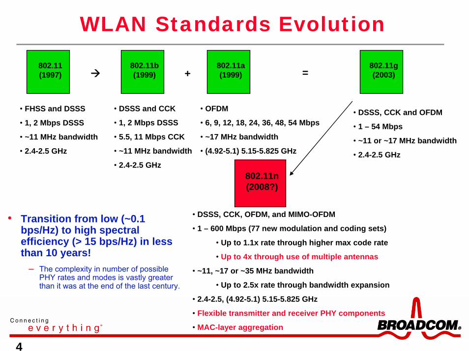
WLAN Standards Evolution
• FHSS and DSSS
• 1, 2 Mbps DSSS
• ~11 MHz bandwidth
• 2.4-2.5 GHz
802.11 (1997)
• DSSS and CCK
• 1, 2 Mbps DSSS
• 5.5, 11 Mbps CCK
• ~11 MHz bandwidth
• 2.4-2.5 GHz
802.11b (1999)
• OFDM
• 6, 9, 12, 18, 24, 36, 48, 54 Mbps
• ~17 MHz bandwidth
• (4.92-5.1) 5.15-5.825 GHz
802.11a (1999)
• DSSS, CCK and OFDM
• 1 – 54 Mbps
• ~11 or ~17 MHz bandwidth
• 2.4-2.5 GHz
802.11g (2003)=+
• DSSS, CCK, OFDM, and MIMO-OFDM
• 1 – 600 Mbps (77 new modulation and coding sets)
• Up to 1.1x rate through higher max code rate
• Up to 4x through use of multiple antennas
• ~11, ~17 or ~35 MHz bandwidth
• Up to 2.5x rate through bandwidth expansion
• 2.4-2.5, (4.92-5.1) 5.15-5.825 GHz
• Flexible transmitter and receiver PHY components
• MAC-layer aggregation
802.11n (2008?)
• Transition from low (~0.1 bps/Hz) to high spectral efficiency (> 15 bps/Hz) in less than 10 years!
– The complexity in number of possible PHY rates and modes is vastly greater than it was at the end of the last century.

5
802.11, 802.11b/g/n Regulatory Landscape
2400 2412 2437 2462 2483.5 MHz
channel 1 channel 6 channel 11
Set 1: Non-overlapping
5.5 & 11 Mbps
2400 2412 2422 2432 2442 2452 2462 2472 2483.5 MHz
ch 1 3 5 7 9 11
Set 2: Overlapping
1 & 2 Mbps
In North America

6
20 20 20 MHz
5150 5350 MHz
30 20 30 MHz
5725 5825 MHz
802.11a/n Regulatory Landscape
lower* middle* upper band40mW 200mW 800mW Pmax
indoor indoor outdoor* +23 dBm EIRP for ETSI
5470 5725 MHz
30 20 25 MHz
U-NII Low/Middle Bands and ETSI Low Band
ETSI High Band
U-NII High Band
upper band+30 dBm* EIRPmax
* except for ch. 140
+23 dBm EIRP
Additional channels from 4920 to 5080 MHz are defined only in Japan.

7
Why Do We Need > 54 Mbps?
• First answer: very good question. ☺
• On second thought:– For multiple-stream compressed video transmission
– For wireless connections to content stored in one place in the home (NAS)
– Because it’s faster than what is available today and eventually will be of equivalent price. (Our experience: speed sells.)
HDTV receiver+ PVR
Local content storage
HD Monitor

8
Outline
• IEEE 802.11 Overview
• The Indoor Wireless Channel
• Approaches to Improving Robustness and Data Rate
• More 802.11n Draft Details
• MIMO Transceiver Design Challenges and Solutions
• Broadcom’s First MIMO Baseband IC

9
• Multipath with Strong LOS– Below is an example of a multipath channel in the presence of a strong LOS path
– Vector r represents the mean value of the possible resultant vectors
– The area of the circle indicates the 50% contour for the distribution
– Vector magnitude indicates that probability of error is small
– If the non-LOS components adhere to a Rayleigh distribution, the underlyingdistribution of the sum is Ricean.
Multipath Channels: LOS
Access Point
Client
Φ∠= rrr
Fig. after ref [1]

10
Multipath Channels: Non-LOS• Multipath:
– Is caused by the multiple arrivals of the transmitted signal to the receiver due to reflections off “scatterers” (walls, cabinets, people, etc.).
– For most indoor wireless systems, it is generally more problematic if a direct line-of-sight (LOS) path does not exist between the transmitter and the receiver
– If incident waves are uniformly distributed over solid angle, the fade depth at any location is drawn from a Rayleigh distribution. Many real indoor environments approximate Rayleigh fading.
Access Point
Client
Fig. after ref [1]

11
Multipath Channels: Spatial Selectivity
• Received signal power as a function of receiver-to-transmitter distance for a multi-GHz transmission in a multi-path indoor environment is shown below.
– Received signal power can vary quite significantly with a slight change in distance
• The fade may be frequency selective if the channel impulse response (CIR) is long enough.
• What can we do to mitigate the effects of space and frequency selectivity?
Fig. after ref [2]
12
Outline
• IEEE 802.11 Overview
• The Indoor Wireless Channel
• Approaches to Improving Robustness and Data Rate
• More 802.11n Draft Details
• MIMO Transceiver Design Challenges and Solutions
• Broadcom’s First MIMO Baseband IC
13
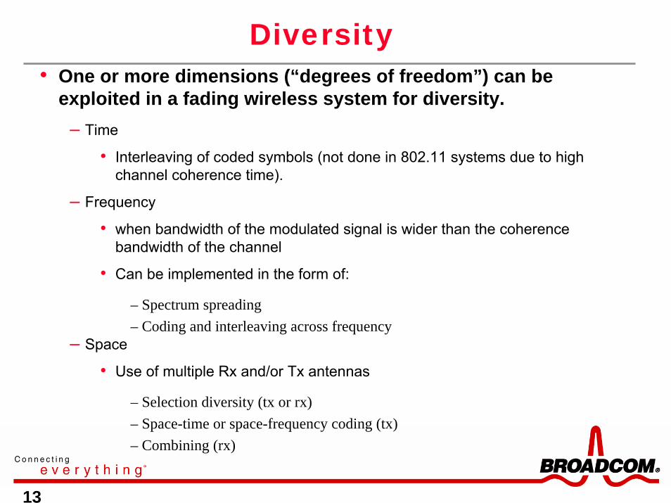
Diversity• One or more dimensions (“degrees of freedom”) can be
exploited in a fading wireless system for diversity.– Time
• Interleaving of coded symbols (not done in 802.11 systems due to high channel coherence time).
– Frequency
• when bandwidth of the modulated signal is wider than the coherence bandwidth of the channel
• Can be implemented in the form of:
– Spectrum spreading– Coding and interleaving across frequency
– Space
• Use of multiple Rx and/or Tx antennas
– Selection diversity (tx or rx)– Space-time or space-frequency coding (tx)– Combining (rx)

14
Wideband Modulation over the Wireless Channel
-8.125 -.3125 .3125 8.125 MHz
Subcarrier Index-26 -1 +1 +26
-8.125 8.125 MHz
Broadband channel with no OFDM subdivision Multipath channel response
Broadband channel with many OFDM (narrowband) subcarriers
• The received signal in a multi-path environment will suffer “fades” as shown below.
• For wideband channels (as in 802.11n) the fade is often frequency-selective.
• Orthogonal Frequency Division Multiplexing (OFDM) divides the frequency-selective channel into approximately frequency-flat bins through an orthogonal transform.

15
OFDM and Frequncy Diversity in 802.11n• The 802.11n standard is based on OFDM.
• OFDM addresses multi-path frequency selectivity and introduces frequency diversity through subdivision of the channel into parallel approximately flat-fading sub-channels and coding+interleaving across frequency (e.g., BICM).
• Signal is sub-divided into N sub-carriers, which are orthogonal to each other under certain conditions, through the use of an orthogonaltransformation such as the DFT/IDFT.
– Typically, a cyclic prefix (CP) is defined to ensure orthogonality in the presence of a multipathchannel.
• The values of the CP may be the last M samples of the output of the IDFT.
• The guard interval (GI), or duration of the CP, is chosen to be somewhat longer than typical long channel.
– Orthogonality deteriorates because of long channels, phase noise, distortion, frequency inaccuracy, IQ imbalance, …
• Causes inter-subcarrier interference and possibly inter-symbol interference
ff

16
Multi-Antenna Systems: Spatial Diversity
• Can be achieved by using multiple antennas at the transmitter or the receiver• Antennas are required to be placed “sufficiently” far apart in order to
– Need to have uncorrelated signal envelope values at antenna inputs.
– In an indoor environment, an antenna separation of greater than ½ carrier wavelength is often quoted as the minimum separation to exploit spatial diversity.
– In practice, smaller separations may be used.
0 0.2 0.4 0.6 0.8 1 1.2 1.4 1.6 1.8 20
0.1
0.2
0.3
0.4
0.5
0.6
0.7
0.8
0.9
1
d/λ
L(d)
Covariance of signal envelope (Rayleigh fading)
L(d) = J02(2*pi*d/λ) 5.24 GHz measured
indoor channels (40 MHz BW)
( ) ( )
( ) ( ) ( ) ( )2/11
0
1
0
*2/11
0
1
0
*
1
0
1
0
*
,
,ˆ,ˆ,ˆ,ˆ
,ˆ,ˆ
⎟⎠
⎞⎜⎝
⎛⋅⋅⎟
⎠
⎞⎜⎝
⎛⋅
⋅=
∑∑∑∑
∑∑−
=
−
=
−
=
−
=
−
=
−
=
K
k
N
ikk
K
k
N
ikk
K
k
N
ikk
rxlm
liHliHmiHmiH
liHmiHR
( ) ( ) ∑∑−
=
−
=
⋅⋅
−=1
0
1
0
),(1,,ˆK
k
N
nkkk jnH
NKjiHjiH

17
Selection Diversity Using RSSI• In a simple Rx selection-diversity system:
– Received power at each antenna is examined in turn (during preamble processing, for example)
• Often a “diversity switch” is used to multiplex the antennas to the common receiver block
– The antenna path with the largest signal strength is selected
Ant. Div.Switch
Radio ADC PHY + MACAnt.2
Ant.1
Ant.Tx
TxCHANNEL L > λ/
2

18
RF
Antenna Selection Criteria
RSSI (total received power=desired signal+interference+thermal noise)
Channel & Interference Estimation
SINRestimation
BERestimation
decoder bits
Capacityestimation
A1
A2
A1 A2 A1 A2

19
Maximal Ratio Combining (MRC)• One can also combine antenna outputs instead of selecting the “best” set.
• In OFDM, MRC may be performed on a per subcarrier (m=1..num_subcarriers) basis to help reduce multipath deep nulls.
• The combiner weights from each branch are adjusted independently from other branches according to its branch SNR:
Now, can we exploit multipath propagation to increase data rates?
Fig. after ref [3]
kmkm
km
M
k
Hkmmmmkmkm
hw
rwyxhr
,,
,1
,,, ,
=
⋅=+⋅= ∑=
η
CombinerTX hm,3xm rm,3

20
Exploiting Multipath for Higher Rates:Constant-energy Capacity Increase
Each circle represents a location on one floor of an office building with offices, cubicles and labs. Notice the roughly linear increase in capacity. σ are the singular values of H.
The ratio of the first to second singular value decreases as M and N increase There is always a benefit to using more antennas for k <= min(M,N) spatial streams, though the benefit diminishes.
( ) ⎟⎟⎠
⎞⎜⎜⎝
⎛+⋅≤⎟⎟
⎠
⎞⎜⎜⎝
⎛⋅+=⎟
⎟⎠
⎞⎜⎜⎝
⎛⎥⎦
⎤⎢⎣
⎡⋅⋅+= ∑
−
= TXRXTX
N
nnk
TXkk
TXNk N
NNN
HHN
IRX ρσρρη 1log,min1logdetlog 2
1
0
2,2
*2
Red: ratio of 2nd
to 1st singular value
Green: ratio of 3rd to 1st singular value
Magenta: ratio of 4th to 1st
singular value

21
Space Division Multiplexing (SDM) with MIMO-OFDM
• In OFDM, the channel is broken into L (in this case, 53) parallel flat-fading channels, each represented by a single complex coefficient.
• In MIMO OFDM, there is an NxMcomplex-valued matrix of channel coefficients per subcarrier, where M is the number of transmitter antennas and N is the number of receiver antennas. -26 0 25 26-24-25 1-1
Carrier Frequency (fc)
H-24(0,0)
H-24(1,1)
H-24(0,1) H-24(1,0) MIMORX
MIMOTX
bits outbits in
OFDM Subcarrier Index
( )( )
( ) ( )( ) ( )
( )( )
( )( )⎟⎟⎠⎞
⎜⎜⎝
⎛+⎟⎟
⎠
⎞⎜⎜⎝
⎛⋅⎟⎟
⎠
⎞⎜⎜⎝
⎛=⎟⎟
⎠
⎞⎜⎜⎝
⎛
−
−
−
−
−−
−−
−
−
10
10
1,10,11,00,0
10
24
24
24
24
2424
2424
24
24
NN
XX
HHHH
YY

22
Space Division Multiplexing (SDM) Receivers
• One can transmit an independent data stream on each transmit antenna provided the receiver has at least two antennas.
• In this 2x2 SDM case, the data may be recovered perfectly on any subcarrier if its 2x2 channel matrix is invertible (2 equations, 2 unknowns) and SNR is high enough.
• The simplest linear receiver inverts the channel matrix to recover transmitted symbols and is referred to as “Zero-Forcing”.
-26 0 25 26-24-25 1-1
Carrier Frequency (fc)
H-24(0,0)
H-24(1,1)
H-24(0,1) H-24(1,0) MIMORX
MIMOTX
bits outbits in
OFDM Subcarrier Index
( )( )
( ) ( )( ) ( )
( )( )⎟⎟⎠⎞
⎜⎜⎝
⎛⋅⎟⎟
⎠
⎞⎜⎜⎝
⎛=⎟⎟
⎠
⎞⎜⎜⎝
⎛
−
−−
−−
−−
−
−
10
1,10,11,00,0
1ˆ0ˆ
24
241
2424
2424
24
24
YY
HHHH
XX
"Zero-Forcing" Receiver

23
Outline
• IEEE 802.11 Overview
• The Indoor Wireless Channel
• Approaches to Improving Robustness and Data Rate
• More 802.11n Draft Details
• MIMO Transceiver Design Challenges and Solutions
• Broadcom’s First MIMO Baseband IC

24
Throughput-Enhancing Features of 802.11n
• Space Division Multiplexing (SDM)
• Higher code rate (up to 5/6)
• Greater signal bandwidth
• MAC-layer aggregation and block acknowledgment (Block ACK)

25
Rate-increasing Modulation and Coding Schemes
• Constructing a basic rate table– 8 modulation+coding sets (MCSs) for 1
spatial stream
– Range from BPSK rate ½ to 64-QAM rate 5/6
– Data rates range from 6.5 Mbps to 65 Mbps (72.2 Mbps with short GI)
• Additional streams are added in a similar manner for SDM
– E.g., MCS 8 is BPSK rate=1/2 for each of two streams (13 Mbps).
– And, so on..
Index Modulation Code Rate
Data Rate (Mbps)
0 BPSK ½ 6.5
1 QPSK ½ 13
2 QPSK ¾ 19.5
3 16-QAM ½ 26
4 16-QAM ¾ 39
5 64-QAM 2/3 52
6 64-QAM ¾ 58.5
7 64-QAM 5/6 65

26
Fragment of the 802.11n Draft Modulation/Coding Set (MCS)
NES NSD NCBPS
GI = 800ns GI = 400ns
Rate in Rate in Rate in Rate in
20MHz 40MHz 20MHz 40MHz
0 1 BPSK ½ 1 1 52 108 52 108 6.5 13.5 7 2/9 15
1 1 QPSK ½ 1 1 52 108 104 216 13 27 14 4/9 30
2 1 QPSK ¾ 1 1 52 108 104 216 19.5 40.5 21 2/3 45
3 1 16-QAM ½ 1 1 52 108 208 432 26 54 28 8/9 60
4 1 16-QAM ¾ 1 1 52 108 208 432 39 81 43 1/3 90
5 1 64-QAM ⅔ 1 1 52 108 312 648 52 108 57 7/9 120
6 1 64-QAM ¾ 1 1 52 108 312 648 58.5 121.5 65 135
7 1 64-QAM 5/6 1 1 52 108 312 648 65 135 72 2/9 150
8 2 BPSK ½ 1 1 52 108 104 216 13 27 14 4/9 30
9 2 QPSK ½ 1 1 52 108 208 432 26 54 28 8/9 60
10 2 QPSK ¾ 1 1 52 108 208 432 39 81 43 1/3 90
11 2 16-QAM ½ 1 1 52 108 416 864 52 108 57 7/9 120
12 2 16-QAM ¾ 1 1 52 108 416 864 78 162 86 2/3 180
13 2 64-QAM ⅔ 1 1 52 108 624 1296 104 216 115 5/9 240
14 2 64-QAM ¾ 1 1 52 108 624 1296 117 243 130 270
15 2 64-QAM 5/6 1 1 52 108 624 1296 130 270 144 4/9 300
20 4020 40 20MH
z40MH
z
Bits 0-6 in HT-SIG1 (MCS index)
Number of spatial streams Modulation
Coding rate
Maximum rate in shipping products today.
MCS indices 16-31 cover 3- and 4-spatial-stream symmetric encodings. MCS 32 is a special frequency-diverse mode. MCS indices 33-77 cover asymmetric encodings.

27
802.11n Frame Formats
• The 802.11n Draft defines a “greenfield” and a “mixed mode” format.– “Greenfield” frames are used for channels and time periods during which all legacy devices are inactive.– “Mixed mode” frames include a legacy prefix to trigger physical carrier sense of legacy devices.
• The “high-throughput” (HT) and legacy short training fields (HT-STF and L-STF) use the 802.11a short symbols with cyclic shifts on additional antennas.
– Different shifts are used on HT and legacy portions.
• The HT long training fields use the 802.11a long symbols with cyclic shifts on additional antennas and multiplication by a matrix with orthogonal columns.
– [1 1; 1 -1] for 2 spatial mapper inputs.– [1 -1 1 1; 1 1 -1 1; 1 1 1 -1; -1 1 1 1] for 3 and 4 spatial mapper inputs.– STBC 2x1 is defined in the spec. as “2 spatial-mapper inputs” (NSMI = 2).
L
L
n is 1, 2, and 4 for NSMI = 1, 2, and 4 and 4 for NSMI = 3.

28
HT-LTF Construction• The HT-LTFs are constructed using the following base matrix:
• The following table shows the number of HT-LTFs transmitted for frames using 1-4 spatial mapper inputs:
• For 1-3 spatial streams, the bottom row(s) of the PHT-LTF matrix shown above is (are) deleted.
1 1 1 11 1 1 11 1 1 11 1 1 1
HTLTFP
−⎛ ⎞⎜ ⎟−⎜ ⎟=⎜ ⎟−⎜ ⎟−⎝ ⎠
Number of spatial mapper inputs (NSMI) Number of HT-LTFs
1 1
2 2
3 4
4 4

29
High-Throughput SIGNAL Field (HT-SIG)
• Each 4-usec symbol in the HT-SIG field is encoded as +90-degree rotated BPSK.– Distinguishing HT-SIG in from legacy transmissions is straightforward.
• HT-SIG1 is the first HT-SIG symbol transmitted in time.
Q
I
+1
+1-1-1
Q
I
+1
+1-1-1
11
0
0
Q
I
+1
+1-1-1
Q
I
+1
+1-1-1
11
0
0
L-SIG HT-SIG

30
• For 802.11n 20MHz mode, the spectral mask floor is set to -45dBr.• For 802.11n 20MHz mode, there are a total of 56 subcarriers (indices-
28 through 28 with 0 excluded) – 8% increase in PHY rate relative to legacy A/G
Bandwidth Extension: 802.11n 20MHz Mode Spectral Mask
-20 -9-11-30 3020119
0dBr
-20dBr-28dBr
-45dBr
Freq [MHz]
PSD
-28 +28Subcarrier Index
5 dB tighter than 802.11a/g
31
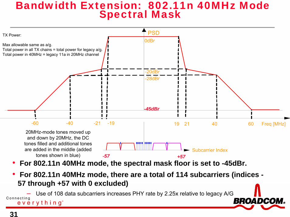
• For 802.11n 40MHz mode, the spectral mask floor is set to -45dBr.• For 802.11n 40MHz mode, there are a total of 114 subcarriers (indices -
57 through +57 with 0 excluded) – Use of 108 data subcarriers increases PHY rate by 2.25x relative to legacy A/G
-40 -19-21-60 60402119
0dBr
-20dBr-28dBr
-45dBr
Freq [MHz]
PSD
-57 +57Subcarrier Index
20MHz-mode tones moved up and down by 20MHz, the DC
tones filled and additional tones are added in the middle (added
tones shown in blue)
TX Power:
Max allowable same as a/g. Total power in all TX chains = total power for legacy a/g. Total power in 40MHz = legacy 11a in 20MHz channel
Bandwidth Extension: 802.11n 40MHz Mode Spectral Mask

32
MAC Improvements: Why Aggregate Frames?
• RTS/CTS/A-MPDU/IBA vs. DATA/ACK improvement– At a 300 Mbps PHY rate, 60 Mbps throughput is the upper bound for a UDP-like flow with an
unmodified DCF MAC.
– Throughput is around 180 Mbps (or better) with A-MPDU and Immediate BA
MAC Efficiency 802.11a - 1500 Byte frames
0%
10%
20%
30%
40%
50%
60%
70%
80%
90%
100%
0 100 200 300 400 500
PHY Bit Rate (Mbps)
MAC PayloadBackoffIFSACK ovhdPHY hdrMAC hdr+fcs
MAC Efficiency 802.11a A-MPDU+IBA+Coll(=1/cwmin)4096-Byte frames - OFDM RTS/CTS
0%10%20%30%40%50%60%70%80%90%
100%
0 100 200 300 400 500
PHY Bit Rate (Mbps)
MAC PayloadRTS/CTSCollisionBackoffIFSACK ovhdPHY hdrMAC hdr+fcsSEC ovhd

33
A-MPDU Aggregation• Control and data MPDUs (MAC Protocol Data Units) can be
aggregated• PHY has no knowledge of MPDU boundaries
Dat
a M
PDU
Agg
rega
teH
T P
PD
U
Dat
a M
PDU
Dat
a M
PDU
Initi
ator
Tx
Act
ivity
PHY
TxM
AC
Tx
Res
pond
er T
x A
ctiv
ityP
HY
TxM
AC
Tx
Blo
ck A
ck
Lega
cy
PPD
UR
TS
Lega
cy
PPD
UC
TS
Dat
a M
PDU
Dat
a M
PDU
Dat
a M
PDU
Blo
ck A
ck
Dat
a M
PDU
Dat
a M
PDU
Dat
a M
PDU
Dat
a M
PDU
Dat
a M
PDU
Dat
a M
PDU
Implicit Block Ack Protocol
RTS/CTSProtocol
Dat
a M
PDU
Dat
a M
PDU
Agg
rega
teH
T P
PD
U
Lega
cy
PPD
U
Lega
cy
PPD
U
A-MPDU + Block ACK provide the most significant boost to MAC efficiency.
34
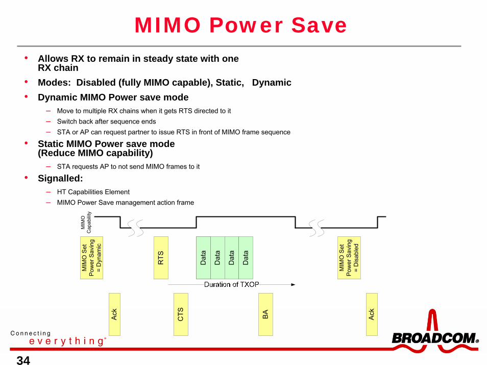
MIMO Power Save
MIM
O S
et
Pow
er S
avin
g =
Dyn
amic
CTS
Dat
a
Ack
MIM
O
Cap
abili
ty
RTS
Dat
a
BA
Dat
a
Dat
a
Dat
a
MIM
O S
et
Pow
er S
avin
g =
Dis
able
d
Ack
• Allows RX to remain in steady state with one RX chain
• Modes: Disabled (fully MIMO capable), Static, Dynamic• Dynamic MIMO Power save mode
– Move to multiple RX chains when it gets RTS directed to it– Switch back after sequence ends– STA or AP can request partner to issue RTS in front of MIMO frame sequence
• Static MIMO Power save mode (Reduce MIMO capability)
– STA requests AP to not send MIMO frames to it
• Signalled:– HT Capabilities Element– MIMO Power Save management action frame

35
Outline
• IEEE 802.11 Overview
• The Indoor Wireless Channel
• Approaches to Improving Robustness and Data Rate
• More 802.11n Draft Details
• MIMO Transceiver Design Challenges and Solutions
• Broadcom’s First MIMO Baseband IC

36
Info source
802.11aEnc-Punct-Intlv
Space Intlv
11aQAM
/ IFFT / GI
11aQAM
/ IFFT / GI
FFT
FFT
MIMOSoft
Detect&
Demap
Space De-Intlv
802.11aDe-(Intlv-Punct-Code) Sink
fc
cyclic delay
11a C.E.
11a C.E.
±
±
2x2 SDM In the Context of an OFDM Transmitter/Receiver
2x2 SDM In the Context of an OFDM Transmitter/Receiver
• Space Division Multiplexing (SDM) up to 130 Mbps in 20 MHz bandwidth or 270 Mbps in 40 MHz bandwidth (64-QAM, 5/6 rate)
• Use 400ns cyclic advance on Short Training and 400ns cyclic advance on Long Training, SIGNAL fields and DATA.
• Long Training using time orthogonality between HT-LTF #s 1 and 2; channel estimation in frequency domain reusing 11a/g blocks
between HT-LTF #1 and #2
L-STF L-LTF L-SIG HT-SIG HT-DATA …c400 c400 c400 c400 c400 c400 c400
(+1)(+1)
(+1)(+1)
Legacy compatible preamble
c400 c400(+1)
(-1)
HT-LTFHT-LTF
“Mixed Mode” High Throughput (HT) Frame Format
HT-STF

37
Receiver Types for SDM
• Zero Forcing (ZF)– Simplest receiver type (covered in intro to SDM)– Poor performance on channels with high condition number and at low SNR
• Nrx > Nss in general for decent performance
• MMSE-LE– Incorporates knowledge of input SNR– Far higher complexity than ZF but better performance at low SNR– Poor performance on channels with high condition number
• Nrx > Nss in general for decent performance
• Interference-cancelling– Suffers large losses from error propagation with one FEC encoder
• Generally a poor choice for 802.11n
• ML Detector– Best performance achievable open-loop while also meeting rx-tx timing requirement– Achieves full diversity– High complexity without clever tricks

38
ML Detector and Complexity
• 2x2 MIMO system using M2-QAM modulation
• Brute force MLD– Log-likelihood ratio for bit k is – Must compute for each M4 possible combination of QAM symbols– Requires 20M4 multiplies and 12M4 adds per subcarrier per 4D symbol– Provides receiver diversity order 2 with two antenna outputs
• Complexity of efficient approach (per subcarrier per 4D symbol):– M2/8 + M/4 + 73 multiplies, [18 + 4log2(M)]M2+78 adds– Also need 4log2M low-precision divisions for global scaling of each LLR by 1/Kσ2
– Comparisons for 64-QAM (M=8)• Brute force ML -- 81920 multiplies and 49152 adds plus overhead• Efficient ML -- 83 multiplies, 1998 adds including overhead
2Hxr −
⎥⎦
⎤⎢⎣
⎡+⎥
⎦
⎤⎢⎣
⎡++
⎥⎦
⎤⎢⎣
⎡=⎥
⎦
⎤⎢⎣
⎡
+=
2
1
,2,2
,1,1
2221
1211
2
1
nn
jxxjxx
hhhh
rr
QI
QI
nHxr
wherex is the transmitted symbol, with xk,I the in-phase component and xk,Q the quadrature component of xk , k = 1,2H is the channel matrixn is the noise: n1 and n2 are i.i.d. complex Gaussian random variables with mean 0 and variance σ2
r is the received signal
2
1|1|2 minmin1 Hxr
xx−⎟⎟
⎠
⎞⎜⎜⎝
⎛−=
=−= kk bbkL
σ

39
2x2 Nss=2 ML Performance – Channel D NLOS
5 10 15 20 25 30 3510
-4
10-3
10-2
10-1
100
13.38
2x2, 16-QAM, R=0.75, 20 MHz, channel D
SNR (dB)
27.6827
.29
21.70
ZF-LE MMSE-LE ML Shannon Limit
5 10 15 20 25 300
0.1
0.2
0.3
0.4
0.5
0.6
0.7
0.8
0.9
1
Pro
b(S
NR
< X
) @ ta
rget
PE
R =
0.
1
11.2212.56
2x2, 16-QAM, R=0.75, 20 MHz, channel D
SNR (dB)
20.66
25.36
20.25
24.94
17.75
20.74
test1_M4_R75_2x2_D_SL: 3.48 minutes, 100 channels X 20 pkts, avg 3.42 SNR pts per pkt, 0.06 dB resolution, avg 0.03 sec per demodtest1_M4_R75_2x2_D_ZF: 136.83 minutes, 100 channels X 20 pkts, avg 3.41 SNR pts per pkt, 0.50 dB resolution, avg 1.20 sec per demodtest1_M4_R75_2x2_D_LE: 140.64 minutes, 100 channels X 20 pkts, avg 3.49 SNR pts per pkt, 0.50 dB resolution, avg 1.21 sec per demodtest1_M4_R75_2x2_D_ML: 172.67 minutes, 100 channels X 20 pkts, avg 3.24 SNR pts per pkt, 0.50 dB resolution, avg 1.60 sec per demod
PE
R

40
2x2 Nss=2 Performance Summary
50 channels, 10 pkts per channel, 10,000 data bits per packet.
CG0
D
B
1. ZF-LE to MMSE-LE gap is more pronounced at lower SNR (smaller constellations at fixed error rate).
2. MMSE-LE/ZF-LE to ML gap is more pronounced on channels with higher condition number (more correlated paths) and at higher code rates (weaker code due to puncturing). I.e., ML helps on poor channels at the highest data rates.

41
802.11n Radio Design Challenges and Baseband Solutions
• Receiver dynamic range– Must deal with desired signals from roughly +5 to almost -100 dBm at the LNA input
– Must deal with blockers with carrier frequency offset as little as 25 MHz away and power as much as 35 dB greater than desired signal
– Requires high-dynamic-range AGC and sensitive carrier detector.
• Transmit error vector magnitude (EVM)– Must meet tight EVM requirements for highest OFDM rate (< -28 dB)
• Requires minimizing phase noise and I-Q imbalance (nonlinear impairments)
• Requires tight control of output power to avoid PA saturation region
• Additional challenges for compact direct-conversion receivers– Receiver DC offset
– Local oscillator (LO) feedthrough at transmitter
– I-Q imbalance

42
Using the Baseband to Detect/Mitigate LOFT and I-Q Imbalance in Tx
• Only LOFT shown for simplicity.
• Inject Sinusoid at FBB.
• ADC+FFT to detect FBB or 2*FBB.
• LOFT at FBB, I/Q imbalance at 2*FBB.
RFPGA PAD
LOI
LOQ
BB_I
BB_Q
To ext. PA or
AntennaGm
Gm
LPF
LPF
DAC
DAC
ENV DET
Im FLO+FBBFLO
0 FBB 2*FBB
Sinusoids at FBB
LPFG

43
Po=-5dBm; EVM= -40dB @ 5.24GHz
Po=-2dBm; -41dB @ 2.484GHzFrf = 5.24GHz
Post-calibration Phase Noise and EVM Results
Figs. after ref [4]

44
The Need for a Flexible Transceiver
Constellations
Code Rates
Channelizations
Frequency Maps
TX Modes
RX Modes
40 MHz duplicated spectrum mode
Preambles
300 144 4/9270 130 129662410852115/664-QAM215
270 130 243 117 12966241085211¾64-QAM214
240 115 5/9216 104 12966241085211⅔64-QAM213
180 86 2/3162 78 8644161085211¾16-QAM212
120 57 7/9108 52 8644161085211½16-QAM211
90 43 1/381 39 4322081085211¾QPSK210
60 28 8/954 26 4322081085211½QPSK29
30 14 4/927 13 2161041085211½BPSK28
15072 2/9135 65 64831210852115/664-QAM17
13565 121.558.56483121085211¾64-QAM16
12057 7/9108 52 6483121085211⅔64-QAM15
9043 1/381 39 4322081085211¾16-QAM14
6028 8/954 26 4322081085211½16-QAM13
4521 2/340.519.52161041085211¾QPSK12
3014 4/927 13 2161041085211½QPSK11
157 2/913.56.5108521085211½BPSK10
40MHz20MHz40MHz20MHz
Rate inRate inRate inRate in40MHz
20MHz
40204020
GI = 400nsGI = 800ns
NCBPSNSDNES
Coding rateModulation
Number of spatial streams
Bits 0-6 in HT-SIG1 (MCS index)
Standards uncertainty and a large number of mode, preamble, and frequency map combinations mandated a flexible implementation.
Greenfield, Mixed mode, Legacy
Single output, Cyclic delay diversity, SDM
Single input, MRC, SDM
Fig. after ref [5]

45
Outline
• IEEE 802.11 Overview
• The Indoor Wireless Channel
• Approaches to Improving Robustness and Data Rate
• More 802.11n Draft Details
• MIMO Transceiver Design Challenges and Solutions
• Broadcom’s First MIMO Baseband IC

46
An Example: Programmable TX Engine
Encoder / Puncturer /Interleaver
EngineData
Scramble
MACbytes
SIGField
EngineTail bits
QAM
QAM
QAM-to-QAM
StreamMapper
Tone Mapper
TX1
Tone Mapper
TX2
PilotScrambling
Engine
F-dom &Tone Map
Tables
PilotScrambling
Tables
SIG FieldConstruction
Tables
QAM-to-QAMStream Map
Tables
IFFT SampleReadout
IFFT SampleReadout
Frame StructTables
Start, Length
Upsampling
T-domSeq’s (ST)
Upsampling
Start, Length
Start, Length(from Frame
Struct Tables)
I/QComp
I/QComp
PNGenerator
T-domReadout
Control
SELECT SELECT
SELECT
MODE
SELECTSELECT
MAC TxCTRL word
Tail / Pad Bits
Tail bits
Interleaver /Punct
Params
SELECT
Frame Struct EngineVarious SELECT’s
(includingF-dom Trainings)
*
*
*
(includesgeneration of
CRC field)

47
Baseband Block Diagram (Showing Radio Interconnections)
• Supported interfaces: JTAG (both for test and radio control), GPIOS, OTP interface, PCI/Cardbus, PCI-Express
• Maximum supported PHY rate: 270 Mbps (includes proprietary 256-QAM mode for test)
• Full hardware support for TKIP, AES and WEP
• Support for non-simultaneous activity in multiple bands (2.4-2.5 and 4.92-5.925 GHz)
Silic
on B
ackp
lane
10b
DA
Cs
10b
AD
Cs
8b A
DC
10b
DA
Cs
10b
AD
Cs
8b A
DC
48
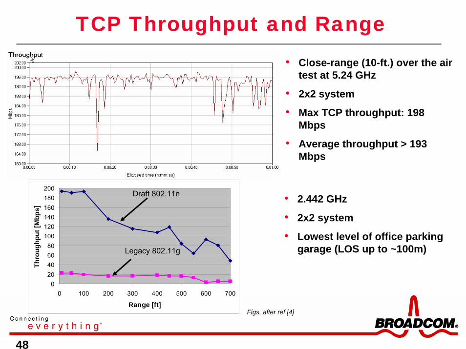
TCP Throughput and Range• Close-range (10-ft.) over the air
test at 5.24 GHz
• 2x2 system
• Max TCP throughput: 198 Mbps
• Average throughput > 193 Mbps
Figs. after ref [4]
020406080
100120140160180200
0 100 200 300 400 500 600 700
Range [ft]
Thro
ughp
ut [M
bps]
Legacy 802.11g
Draft 802.11n • 2.442 GHz
• 2x2 system
• Lowest level of office parking garage (LOS up to ~100m)

49
3x3 with Selection Diversity
6 dB
24 26 28 30 32 34 36 38 4010-3
10-2
10-1
100 2-of-3 selection improvement: MCS15, 20 MHz, ch. B NLOS, 1000B
input SNR (dB)
Fram
e E
rror
Rat
e
2x3 (rx only)3x3 (rx, tx)2x2
BB IC2x2 MIMO
BaseBand/MAC& SystemInterface
2x2 MIMOFront End
Module
RF Connector(Antenna 0)
RF Connector(Antenna 2)
PCI-E RF IC2x2 MIMO
Radio
2GHz Rx B
5GHz Rx B
2GHz Tx B
5GHz Tx B
5GHz Tx B
2GHz Tx B
5GHz Rx B
2GHz Rx B
PA En, Sw Ctrl
RF 0
RF Connector(Antenna 1)
SPDT SW’s
RF 1
50
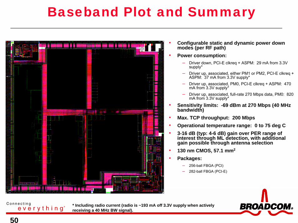
Baseband Plot and Summary
• Configurable static and dynamic power down modes (per RF path)
• Power consumption: – Driver down, PCI-E clkreq + ASPM: 29 mA from 3.3V
supply*– Driver up, associated, either PM1 or PM2, PCI-E clkreq +
ASPM: 37 mA from 3.3V supply*– Driver up, associated, PM0, PCI-E clkreq + ASPM: 470
mA from 3.3V supply*– Driver up, associated, full-rate 270 Mbps data, PM0: 820
mA from 3.3V supply*
• Sensitivity limits: -69 dBm at 270 Mbps (40 MHz bandwidth)
• Max. TCP throughput: 200 Mbps• Operational temperature range: 0 to 75 deg C• 3-16 dB (typ: 4-6 dB) gain over PER range of
interest through ML detection, with additional gain possible through antenna selection
• 130 nm CMOS, 57.1 mm2
• Packages:– 256-ball FBGA (PCI)– 282-ball FBGA (PCI-E)
* Including radio current (radio is ~193 mA off 3.3V supply when actively receiving a 40 MHz BW signal).

51
Acknowledgments
With many thanks to the following individuals who have contributed to the slides and/or reviewed the material:
Dr. Ed Frank
Dr. Nambi Seshadri

52
References[1] A. Behzad, “The Implementation of a High Speed Experimental Transceiver Module with an
Emphasis on CDMA Applications”, Electronic Research Labs, U.C. Berkeley, 1994.[2] T. S. Rappaport. Wireless Communications – Principles and Practice, IEEE Press, 1996.[3] W.-J. Choi, et. al., “MIMO Technology for Advanced Wireless Local Area Networks”, DAC,
June 2005.[4] A. Behzad, et. al., “A Fully Integrated Multiband Direct Conversion CMOS Transceiver for
MIMO WLAN Applications (802.11n)”, ISSCC 2006.[5] IEEE 802.11n Draft 2.0, 2006.
[6] A. Behzad, “WLAN Radio Design”, ISSCC Tutorial, 2004.[7] D. Browne, “Experiments with an 802.11n Radio Testbed”, UCLA/802.11n committee, July
2005.[8] T. H. Lee, The Design of CMOS RF ICs, Cambridge University Press, Jan. 1998.[9] D. Tse, et. al. Fundamentals of Wireless Communications, Cambridge University Press, 2005.[10] J. Medbo and P. Schramm, “Channel models for HIPERLAN/2,” ETSI/BRAN document no.
3ERI085B.[11] A.A.M. Saleh and R.A. Valenzuela, “A statistical model for indoor multipath propagation,”
IEEE JSAC, vol. 5, 1987, pp. 128-137.[12] V. Erceg, et. al., “Indoor MIMO WLAN Channel Models”, IEEE 802.11-03/161r0a, March 2003.[13] V. Tarokh, et. al., “Space-Time Codes for High Data Rate Wireless Communications:
Performance Criterion and Code Construction”, IEEE Trans. Info. Theory, vol. 44, 1998, pp. 744-765.

53
Thank you