
Hornby Railroad Crosti 9F EM Finescale Conversion. Railroad Crosti 9F...Hornby Railroad Crosti 9F EM...
9
Hornby Railroad Crosti 9F EM Finescale Conversion. Before you start, it is a good idea to have some small containers or snap top poly bags to put screws and components in for safe keeping......much better than crawling about on the floor trying to find lost bits! We converted the tender first, not that this will be needed to test the loco chassis later because there is no electrical engine/tender connection plug and socket, nor any tender pickups. TENDER CONVERSION 1. Invert the tender, and hold in a suitable device. We use a foam cradle – the Peco loco service cradle being ideal. 2. Undo the two screws holding the keeper plate – which are both visible and easily undone. Keeper plate removed and one wheel set removed. 3. Lift out the 3 Hornby wheel sets. 4. Then assemble the Gibson wheel sets onto the appropriate plain axle supplied with the wheels. We used 2x1mm plus 1 x 0.5 mm 2mm bore spacing bushes each side to take up the side play. Assembled wheels with spacing bushes.
Transcript of Hornby Railroad Crosti 9F EM Finescale Conversion. Railroad Crosti 9F...Hornby Railroad Crosti 9F EM...

Hornby Railroad Crosti 9F EM Finescale Conversion.
Before you start, it is a good idea to have some small containers or snap top poly bags to put screws and
components in for safe keeping......much better than crawling about on the floor trying to find lost bits!
We converted the tender first, not that this will be needed to test the loco chassis later because there is no
electrical engine/tender connection plug and socket, nor any tender pickups.
TENDER CONVERSION
1. Invert the tender, and hold in a suitable device. We use a foam cradle – the Peco loco service cradle being ideal.
2. Undo the two screws holding the keeper plate – which are both visible and easily undone.
Keeper plate removed and one wheel set removed.
3. Lift out the 3 Hornby wheel sets.
4. Then assemble the Gibson wheel sets onto the appropriate plain axle supplied with the wheels. We used
2x1mm plus 1 x 0.5 mm 2mm bore spacing bushes each side to take up the side play.
Assembled wheels with spacing bushes.

Enlarged view showing spacers on installed Gibson wheel set.
5. Place wheel sets into the chassis.
All 3 axles in place.
6. Replace the keeper plate and screws. Push test the tender through some track work to ensure all is well.
7. Being a railroad model, there are no brakes to worry about fouling the wheel treads!
LOCO CONVERSION
1. Remove the loco pony truck by undoing the screw at the rear of the pony truck on the loco chassis, and place to
one side. Be careful to catch the spring too.
2. Undo and remove the crankpin screws, remove the valve gear drive cranks and connecting rods and leave them
dangling. Recover the coupling rods and place to one side. Make sure you know which rod is from which side!
3. Remove the loco body from the chassis. Remove the insulating tape to release the wiring from the DCC plug
back to where two wires plunge into the depths of the chassis at the rear. This is to allow some slack when we
remove the keeper plate which these wires are fastened too without straining the soldered connections.
Tape removed from wires along the top.
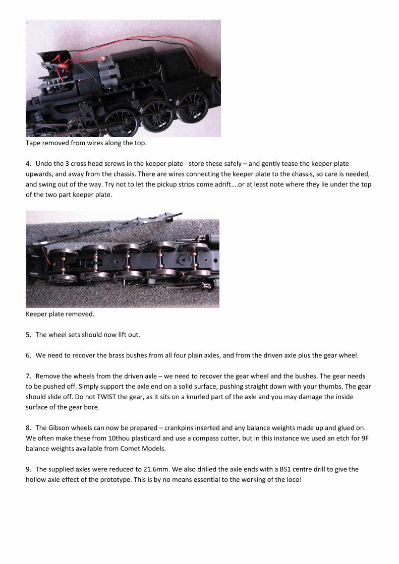
4. Undo the 3 cross head screws in the keeper plate - store these safely – and gently tease the keeper plate
upwards, and away from the chassis. There are wires connecting the keeper plate to the chassis, so care is needed,
and swing out of the way. Try not to let the pickup strips come adrift….or at least note where they lie under the top
of the two part keeper plate.
Keeper plate removed.
5. The wheel sets should now lift out.
6. We need to recover the brass bushes from all four plain axles, and from the driven axle plus the gear wheel.
7. Remove the wheels from the driven axle – we need to recover the gear wheel and the bushes. The gear needs
to be pushed off. Simply support the axle end on a solid surface, pushing straight down with your thumbs. The gear
should slide off. Do not TWIST the gear, as it sits on a knurled part of the axle and you may damage the inside
surface of the gear bore.
8. The Gibson wheels can now be prepared – crankpins inserted and any balance weights made up and glued on.
We often make these from 10thou plasticard and use a compass cutter, but in this instance we used an etch for 9F
balance weights available from Comet Models.
9. The supplied axles were reduced to 21.6mm. We also drilled the axle ends with a BS1 centre drill to give the
hollow axle effect of the prototype. This is by no means essential to the working of the loco!
Wheels complete with weights and crankpins.
10. Now begin to assemble the front, second, third and rear wheelsets. We will need some spacing washers to take
up the side play. We used 2 x 1mm thick washers each side, plus 1 x 0.5 washer per side as well.
11. We use a GW Models wheel press for assembly, which will also quarter the wheels as well as press them on
square.
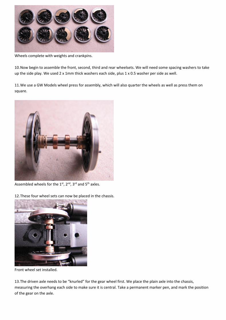
Assembled wheels for the 1st, 2nd, 3rd and 5th axles.
12. These four wheel sets can now be placed in the chassis.
Front wheel set installed.
13. The driven axle needs to be “knurled” for the gear wheel first. We place the plain axle into the chassis,
measuring the overhang each side to make sure it is central. Take a permanent marker pen, and mark the position
of the gear on the axle.

The black dot marks the spot!
14. Place the axle on a cutting mat or similar. Take a small hand file, we use a 6 inch second cut file, and using the
file on edge, roll it with firm downward pressure over the axle where you marked the gear position. Do not stray
away from this narrow area, as the axle revolves in the brass bushes close to the gear, and knurling in this area
won’t help good running!
Not too neat....but it works!
15. The gear can now be slid onto the axle and pressed over the “knurling”. The gear should be central on the axle.
Place in the chassis and check.
Assembled axle and Hornby gear.
16. Assemble the driven axle with spacers and bushes.
17. This can then be installed in the chassis.
Driven axle assembled with spacers and Hornby bushes.

All axles installed.
18. Lift the keeper plate back into position, trying not to let the two parts of it separate, as well as feeding the
pickups carefully behind the wheels, and fasten down with the three screws.
19. You can now place on the track and apply a little power to make sure the driven axle revolves freely.
20. Next we tackle the coupling rods and the connecting rod big ends. The Hornby holes are too large for Gibson
Crankpin bushes, so we need to bush them with the Gibson washers available just for this purpose. First, file the
plating back to the brass base metal on the rear of the rods. Place a washer in the rod hole, and solder in position.
Do this for all 10 coupling rod holes, and do the connecting rods by laying the engine on its side, working on the
rear of the rod which is face down on the work surface. If you fill the bush completely with solder......don’t panic!
As the solder sets, it contracts slightly, leaving a dimple in the centre – use this to as your centre for drilling out. A
suitable drill twiddled with fingers in a pin vice is all that is needed.
The resulting central dimple after over enthusiastic soldering.

21. The bushes then need a gentle opening out to be a good running fit on the crankpin bushes....simply use a
suitable cutting broach and use one of the Gibson bushes as a guide.
22. Assemble the rods onto the wheels. Use a long crankpin bush on the centre wheels, and short ones on the 1st,
2nd, 4th and 5th axles. Fasten with crankpin nuts on the 1st, 2nd, 4th and 5th axles only. Tighten and trim back the 1st
and 2nd axle crankpins, and file the nuts to about half their thickness, in order to give clearance for the connecting
rod. The rear pins can be left for now if you wish and trimmed back before finally fitting the body.
23. The centre crankpins have the valve gear drive crank to retain the rods. The Hornby crank can be re used if you
wish by soldering a 14BA nut into the Hornby crank slot, but this will need widening slightly first.
24. The alternative is to use Alan Gibson cast brass return cranks, and as mentioned above, you will need 2 of these.
25. The new Gibson return cranks need tapping 14BA, and we do this with the cranks still attached to their sprue as
it makes holding easier. The tap is held in a pin vice rather than a normal tap wrench – much easier to use.
Once tapped, they can be cut from the sprue and cleaned up.
Return cranks as supplied with a prepared pair and tap alongside.
26. Wind a crank onto one of the centre crankpins, and naturally it will go tight and stop in the wrong position!
Undo, file a small amount from the rear face of the crank boss, and try again. It will now be tight at a point further
round, so by trial and error, we get it to tighten just forward of the axle centre. Repeat for the opposite side.
Remove the centre cranks, but make sure you know which is for which side!
Fitting the drive cranks.
27. With the coupling rods fitted, we can fit the connecting rods. Place another one of the coupling rod bushes we
used to reduce the hole size in the rods earlier as a spacer on the crankpin before fitting the rod. Then wind on the
crank so it aligns when tightened it is just forward of the axle centre.
28. Repeat for the opposite side.

What the valve gear should now be like!
29. At this point, you should be able to track test the completed valve gear. Gently apply power, checking to ensure
no parts are going to hit other parts or bind. If all is well, admire your engine moving around!
THE PONY TRUCK.
1. Simply twist and pull one Hornby wheel from its axle, and slide the remaining wheel and axle out the other side.
2. Assemble one Gibson wheel onto its axle, and then slide the appropriate spacing washers on, thread through
the pony casting hole, adding the appropriate spacing washers and remaining wheel. Repeat for the second axle.
We used 2 x 1mm 2mm bore brass spacing washers each side.
Re wheeled pony truck.
3. The pony truck has the front steps cast onto it, whereas they should be attached to the footplate. You may wish
to alter this arrangement! For now, ours is left as supplied.
FINAL ASSEMBLY
1. Place the chassis back into the body, and fasten with the two screws.
2. Re place the engine/tender coupling bar and retain with its screw.
3. Replace the pony truck and its spring.
4. Couple up to the tender and you should have a completed loco.
5. Don’t forget to lubricate it!

Pete Hill
September 2015.
Components Used
1 x 4800/34 Driving Wheel Conversion Pack
3 x 4839ST Pony Wheel
1 x 4836ST Tender Wheels
1 x 4M42 Crankpins
1 x 4800 Coupling Rod Bushes
1 x 4M822 Reversing Cranks
1 x 4M67/3 1/8” Washers
1 x 4M67/2 2mm Washers


