Hopper AH4 DISCRIMINATOR - Alberici...6.2 Cctalk Protocol for Hopper AH4 Discriminator ccTalk®...
22
1 Hopper AH4 DISCRIMINATOR 24Vdc ccTalk Operator’s Manual Hopper AH4 II Discriminator Operator’s manual Rev. 1.02
Transcript of Hopper AH4 DISCRIMINATOR - Alberici...6.2 Cctalk Protocol for Hopper AH4 Discriminator ccTalk®...

1
Hopper AH4 DISCRIMINATOR
24Vdc ccTalk
Operator’s Manual
Hopper AH4 II Discriminator
Operator’s manual
Rev. 1.02

2
NOTICE: This manual has been prepared with the utmost care. Nevertheless, it is not possible to
assure at any time the exact correspondence of the descriptiosn to the product features.
Alberici SpA shall not be held liable by the User for any damage, losses, or third party claims
arising from any uses of the manual or of the product.
Alberici S.p.A. maintains the right to modify in any way any part of the present booklet, without
previous notice.

3
Contents
1 GENERAL DESCRIPTION ...................................................................................... 4
1.1 Operation .......................................................................................................................... 4
1.2 Safety ................................................................................................................................ 4
2. TECHNICAL DATA .................................................................................................. 5
3. MECHANICAL DESCRIPTION ................................................................................ 5
3.1 Overall dimensions ......................................................................................................... 5
3.2 Position of the connector ................................................................................................. 6
3.2 Installation ....................................................................................................................... 6
4. ELECTRICAL DESCRIPTION ................................................................................ 6
4.1 Power supply ................................................................................................................... 7
4.2 Current draw .................................................................................................................... 7
4.3 Connector ........................................................................................................................ 7
4.4 Address setting by hardware ........................................................................................... 7
5. MAINTENANCE ..................................................................................................... 8
6. CCTALK PROTOCOL ............................................................................................ 9
6.1 CcTalk commands .......................................................................................................... 9
6.2 Cctalk Protocol for Hopper AH4 Discriminator ........................................................ 10
STORICO REVISIONI
Revisione n° Data Modifica Note
Creazione 1.00 14.09.10 Creazione
Rev. 1.01 24.09.13 Aggiornamento nuova sede Rev. 1.02 22.07.15 Nuovo frontespizio

4
1 GENERAL DESCRIPTION
Dear Customer,
we would like to thank you and congratulate for your choice. We trust that you will appreciate
the quality and performace of the AH4 Discriminator Hopper.
This machine operates by cctalk protocol, the well-established serial communication mode that
provides security and precision.
1.1 Operation
The multi-coin Hopper AH4 Discriminator can be installed onto machines preset for single-coin
cctalk HopperOne or similar Universal Hoppers, using the existing built-in supports, structure
and cables. It contains the disk-driven HopperCD Discriminator II, that identifies the different
coins by means of inductive discrimination. Moreover it is endowed with the exclusive Alberici
SPS (Smart Pick System), the patented device that locates and parks the smaller coins, so a sto
pick them up and pay them out whenever needed to top up the requested amount, which
produces fast and complete payments.
The Hopper AH4 Discriminator can discriminate and count coins and coin-like tokens, whose
diameter ranges from 20 mm to 26,5 mm, and 1,7-3,5 mm thick. The coins and the coin-like
tokens must be round, without indentations, grooves or thick-reliefs. The AH4 is preset to
handle the following coins: 50 €cents, 1 € and 2 €.
The machine board will instruct the Hopper AH4 to pay an amount, not its composition.
A protection system prevents the darkening/blazing of the output sensor, frustrating possible
attempts at cheating the hopper.
In case the output gets jammed or obstructed, the hopper board will detect the overcurrent draw
and will command the motor to briefly rotate the other way round, so as to release the output
and restore the proper operation. This action shall be repeated if one time is not sufficient.
Infra-red sensors allow to monitor the minimum level of the coins contained.
Maximum output speed is 180 coins per minute.
The hopper ccTalk address can be software-defined or hardware-preset: to this purpose, one Dip-
Switch row is made available next to the cctalk 10p connector.
1.2 Safety
The Hopper unit must be installed into systems endowed with ON-OFF mains switch.
Before disconnecting the Hopper AH4 Discriminator, always switch power off.
This products contains rotating and moving mechanical parts: if it is necessary to keep the
machine or this product powered up during servicing or inspecting, DO NOT PUT YOUR
FINGERS INSIDE IT, even though the hopper is not in operation.
Install the AH4 Hopper according to the instructions given in section 2.3. Guarantee decays if
installation is not performed correctly.
WARNING:
the disk of the Hopper AH4 flings
the coins out at high speed (4-5
pieces per second): do not keep
sensitive body parts or fragile
objects in front of the output.
DANGER !
Mechanical parts
In motion !
Please read carefully this handbook, to obtain the most from your AH4.
5
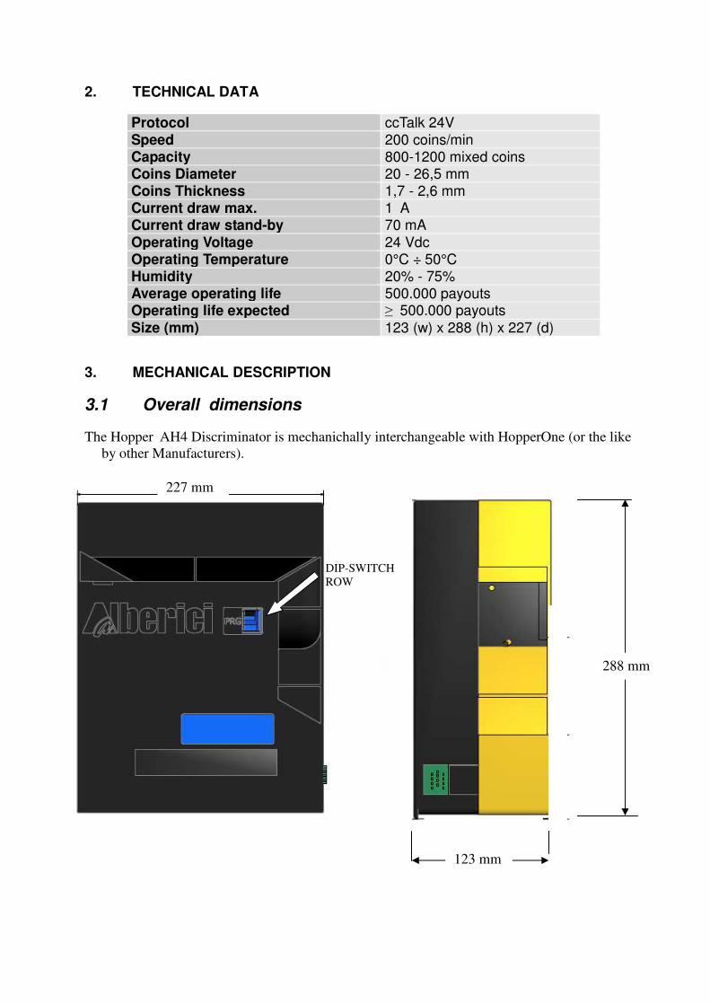
2. TECHNICAL DATA
Protocol ccTalk 24V Speed 200 coins/min Capacity 800-1200 mixed coins Coins Diameter 20 - 26,5 mm Coins Thickness 1,7 - 2,6 mm Current draw max. 1 A Current draw stand-by 70 mA Operating Voltage 24 Vdc Operating Temperature 0°C ÷ 50°C Humidity 20% - 75% Average operating life 500.000 payouts Operating life expected ≥ 500.000 payouts
Size (mm) 123 (w) x 288 (h) x 227 (d)
3. MECHANICAL DESCRIPTION
3.1 Overall dimensions
The Hopper AH4 Discriminator is mechanichally interchangeable with HopperOne (or the like
by other Manufacturers).
123 mm
288 mm
227 mm
DIP-SWITCH
ROW
6
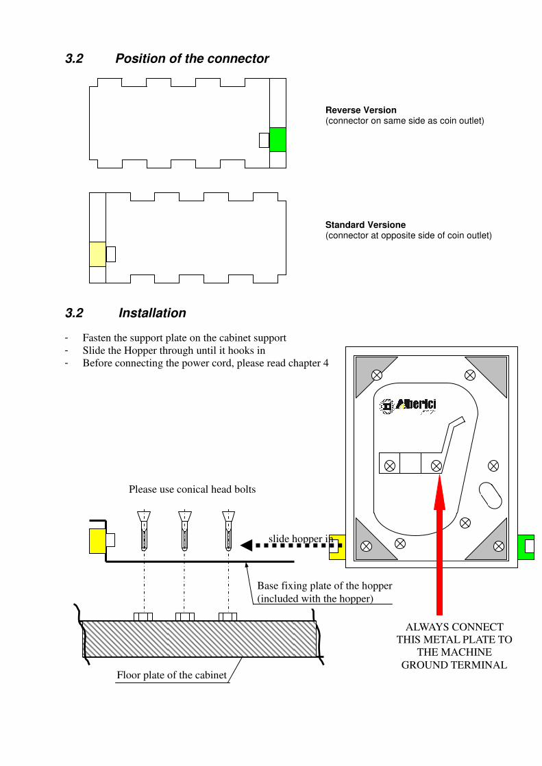
3.2 Position of the connector
3.2 Installation
- Fasten the support plate on the cabinet support
- Slide the Hopper through until it hooks in
- Before connecting the power cord, please read chapter 4
Reverse Version (connector on same side as coin outlet)
Standard Versione (connector at opposite side of coin outlet)
Please use conical head bolts
slide hopper in
Floor plate of the cabinet
ALWAYS CONNECT
THIS METAL PLATE TO
THE MACHINE
GROUND TERMINAL
Base fixing plate of the hopper
(included with the hopper)

7
4. ELECTRICAL DESCRIPTION
4.1 Power supply
Power the Hopper AH4 Discriminator by 24 Vdc (+/-10%) on pin 7 (GND = pin 1). The wire section must be compatible with the current draw.
4.2 Current draw
Standby A vuoto Carico (*)
Circuit board (+24 Vdc) 30 mA 0.72 W 70 mA 1.68 W 70 mA 1.68 W
Motor (+24 Vdc) 0 mA 0 mW 150 mA 3.60 W 1 A * 24.00 W
Total current draw 0.72 W 5.28 W 25.68 W
(*) The motor overload current draw shall always be limited by the electronic circuit. The 1 A draw, corresponding to hold-up of the motor, will therefore be reached only for a few msec.
4.3 Connector
Dip-Switch row for cctalk address
4.4 Address setting by hardware
The serial address of the hopper can be set or modified by software (ccTalk MDCES commands), or by hardware, through the on-board (*) Dip-Switch row, according to the following chart :
Dip-Switch 1 Dip-Switch 2 Dip-Switch 3 N° hopper
Serial address
1 3 ON 2 4
ON 3 5 ON ON 4 6
ON 5 7 ON ON 6 8
ON ON 7 9 ON ON ON 8 10
The state of the new configuration will be read only at reset, therefore any change made without switching power off and again on will have no effect. (*) The Dip-switch row is the one located on the black side wall, signposted by the acronym PRG.
1 2 3
ON
8
5. MAINTENANCE
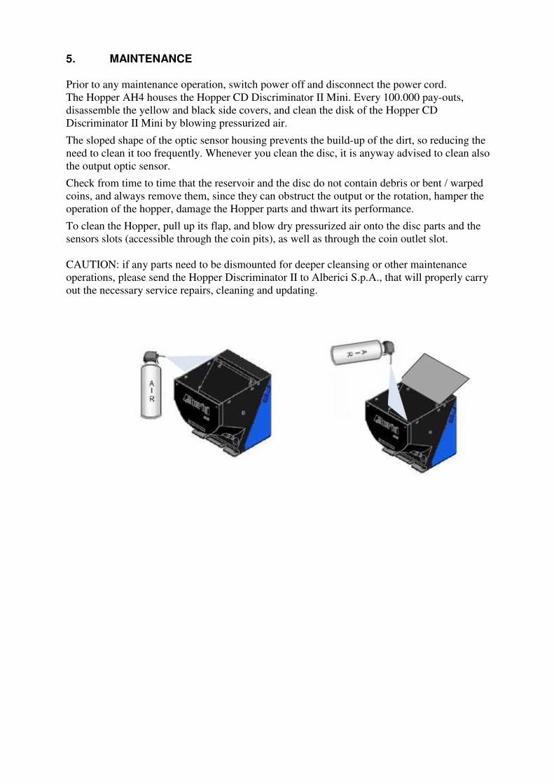
Prior to any maintenance operation, switch power off and disconnect the power cord.
The Hopper AH4 houses the Hopper CD Discriminator II Mini. Every 100.000 pay-outs,
disassemble the yellow and black side covers, and clean the disk of the Hopper CD
Discriminator II Mini by blowing pressurized air.
The sloped shape of the optic sensor housing prevents the build-up of the dirt, so reducing the
need to clean it too frequently. Whenever you clean the disc, it is anyway advised to clean also
the output optic sensor.
Check from time to time that the reservoir and the disc do not contain debris or bent / warped
coins, and always remove them, since they can obstruct the output or the rotation, hamper the
operation of the hopper, damage the Hopper parts and thwart its performance.
To clean the Hopper, pull up its flap, and blow dry pressurized air onto the disc parts and the
sensors slots (accessible through the coin pits), as well as through the coin outlet slot.
CAUTION: if any parts need to be dismounted for deeper cleansing or other maintenance
operations, please send the Hopper Discriminator II to Alberici S.p.A., that will properly carry
out the necessary service repairs, cleaning and updating.

9
6. CCTALK PROTOCOL
6.1 CcTalk commands
NOTICE: the chart below lists the commands needed to implement the Hopper AH4 Discriminator
into the machine board.
Section 6.2 cctalk Protocol for Hopper AH4 Discriminator explains in detail the communication between
Hopper AH4 and host (machine p.c. board).
ccT Code
Hexa. Code
Command header Notes
254 FE Simple poll Return ACK
253 FD Address poll MDCES support
246 F6 Request manufacturer id “Alberici”
245 F5 Request equipment category id “Payout”
244 F4 Request product code “AH DSC 1”
242 F2 Request serial number [Ser nr-L][Ser nr][Ser nr-H]
241 F1 Request software revision un.n pm.m.m
217 D9 Request payout high/low status Return empty/full status
197 C5 Calculate ROM checksum [Mon][Prog][Data]
164 A4 Enable hopper Enable = 0xA5
163 A3 Test hopper Supported
134 86 Dispense hopper value Supported
133 85 Request hopper polling value Supported
132 84 Emergency stop value Supported
131 83 Request hopper coin value Supported
130 82 Request indexed hopper dispense count Supported
1 1 Reset device Software reset

10
6.2 Cctalk Protocol for Hopper AH4 Discriminator
ccTalk® communication protocol is the Money Controls (formally Coin Controls) serial
communication protocol for low speed control networks. It was designed to allow the
interconnection of various cash handling devices (Hopper, Card reader, Bill validators, Coin
selectors etc.), mostly in AWP and gaming Industry, but also in other devices that use those
components.
ccTalk® is an open standard. All documentation is available at web site: www.cctalk.org.
Communication protocol of Alberici Hopper AH04 Discriminator is implemented according to
generic specification 4.4
1 Communication specifications
ccTalk serial communication is derivation of RS232 standard.
Low data rate NRZ (Non Return to Zero) asynchronous communication:
Baud rate 9600, 1 start bit, 8 data bits, no parity, 1 stop bit.
RS232 handshaking signals (RTS, CTS, DTR, DCD, DSR) are not supported.
Message integrity is controlled by means of checksum calculation.
1.1 Baud rate
The baud rate of 9600 was chosen as compromise between cost and speed.
Timing tolerances is same as in RS232 protocol and it should be less than 4%.
1.2 Voltage level
To reduce the costs of connections the “Level shifted “ version of RS232 is used. The idle
state on serial connector is 5V, and active state is 0V.
Mark state (idle) +5V nominal from 3.5V to 5V
Space state (active) 0V nominal from 0.0V to 1.0V
Data I/O line is “open collector” type, so it is possible to use device in systems
with different voltage.
1.3 Connection
The connection of Hopper at network is achieved by means of 10 pole IDC connector
compatible with Azkoyen standard ccTalk 2+2 (Two wires for power supply + and two for
GND connector). Connector is used for power supply and communication as well.
For schematics and connector pinout see image and table below.
PIN Nr. Function
1 ccTalk Data
2 Not used
3 Not used
4 GND
5 Not used
6 Not used
7 +24 V
8 GND
9 Not used
10 +24 V
Table 1 AH04 - ccTalk connector

11
1.4 Message structure
Each communication sequence consists of two message packets.
Message packets for simple checksum case is structured as follows:
[ Destination address ] [ Nr. of data bytes ]
[ Source address ]
[ Header ]
[ Data 1 ] ...
... [ Data n ]
[ Checksum ]
There is an exception of message structure when device answer to instruction 253 “Address
poll” and 252 “Address clash”1. The answer consists of only one byte representing address
delayed for time proportional to address value or random delay.
For CRC checksum case format is:
[ Destination address ]
[ Nr. of data bytes ]
[ CRC 16 LSB ]
[ Header ]
[ Data 1 ]...
... [ Data n ]
[ CRC 16 MSB ]
1.4.1 Address
Address range is from address 0 to address 255. Address 0 is special case or so called
“broadcast” address and address 1 is default host address.
The recommendation for address value of different devices are presented in table 2.
Device category Address Additional addr. Note
Coin Acceptor 2 11 - 17 Coin validator, selector, mech...
Payout 3 4 - 10 Hopper
Bill validator 40 41 - 47 Banknote reader
Card Reader 50 -
Display 60 Alphanumeric LC display
Keypad 70 -
Dongle 80 85 Safety equipment
Meter 90 Replacement for el.mec. counters
Power 100 Power supply
Table 2 Standard address for different types of devices
12
Address for ALBERICI Hoppers is factory set to value 3, but the user can change the default
address by setting the Hopper PCB switch.
1.4.2 Number of data byte
Number of data byte in each transfer could be from 0 to 252.
Value 0 means that there are no data bytes in the message, and total length of message
packet will be 5 bytes. Although theoretically it will be possible to send 255 bytes of data
because of some limitations in small micro controllers the number is limited to 2522.
1.4.3 Command headers (Instructions)
Total amount of possible ccTalk command header is 255, with possibility to add sub-headers
using headers 100, 101, 102 and 103.
Header 0 stands for ACK (acknowledge) replay of device to host.
Header 5 stands for NAK (No acknowledge) replay of device to host.
Header 6 is BUSY replay of device to host.
In all three cases no data bytes are transferred. Use of ACK and NAK headers is explained
separately for each specific message transfer.
Commands are divided in to several groups according to application specifics:
- Basic general commands - Additional general commands - Commands for Coin acceptors - Commands for Bill validators - Commands for Payout
- MDCES commands
1.4.4 Data
There is no restrictions for data format use. Data could be BCD (Binary Coded
Decimal)numbers, Hex numbers or ASCII strings. Interpretation as well as format is specific
to each header use, and will be explained in separate chapter.
1.4.5 Checksum Message integrity during transfer is checked by use of simple zero checksum calculation. Simple checksum is made by 8 bit addition (modulus 256) of all the bytes in the message. If the addition of all bytes are non-zero then an error has occurred.
1.5 Timing specification
The timing requirements of ccTalk are not very critical but there are some recommendation.
1.5.1 Time between two bytes
When receiving bytes within a message packet, the communication software must wait up
to 50 ms for next byte if it is expected. If time out occurs, the software should reset all
communication variables and get ready to receive next message. The inter byte delay
during transmission should be ideally less than 2 ms and not greater than 10 ms.
1.5.2 Time between command and replay
The time between command and reply is dependent on application specific for each
command. Some commands return data immediately, and maximum time delay should be
within 10 ms.
Other commands that must activate actions in device may return reply after action is
ended.
1.5.3 Start-up time

13
After the power-up sequence Hopper should be ready to accept and answer to a ccTalk
message within time period of less than 250 ms.
During that period all internal check-up and system settings must be concluded, and hopper
should be in condition to operate properly.
1.6 Error handling
If slave device receive the message with bad checksum or missing data no further action is
taken and receive buffer will be cleared.
Host software should decide to re-transmit message immediately or after a fixed amount of
time. In case when host receive message with error it has same options.
2. Hopper Command header set
Command header set, that host could use in communication with Hopper is given in table 3.
Code / Hex. Command header Note
254 FE Simple poll Return ACK
253 FD Address poll MDCES support
246 F6 Request manufacturer id “Alberici”
245 F5 Request equipment category id “Payout”
244 F4 Request product code “AH DSC 1”
242 F2 Request serial number [Ser nr-L][Ser nr][Ser nr-H]
241 F1 Request software revision un.n pm.m.m
217 D9 Request payout high/low status Return empty/full status
197 C5 Calculate ROM checksum [Mon][Prog][Data]
164 A4 Enable hopper Enable = 0xA5
163 A3 Test hopper Supported
134 86 Dispense hopper value Supported
133 85 Request hopper polling value Supported
132 84 Emergency stop value Supported
131 83 Request hopper coin value Supported
130 82 Request indexed hopper dispense count Supported
1 1 Reset device Software reset

14
Table 3 List of Hopper AH4 Discriminator ccTalk command headers
Command headers are divided in to 4 different groups: - Common command headers - Hopper command headers - MDCES command headers - ALBERICI specific command headers
2.1.1 Command header 254 [hexFE], Simple poll
The fastest way for host to detect all attached devices in ccTalk network.
Addressed device - Hopper answer with ACK (Acknowledge).
If within predicted amount of time Hopper does not answer, probably is not connected,
powered or simple not working properly.
Message format is: Host sends: [Dir][00][01][FE][Chk] Hopper answer: [01][00][Dir][00][Chk]
Hopper default address is 3, example of message packet is: Host sends: [03][00][01][FE][FE]
Hopper answer: [01][00][03][00][FC] ACK message
2.1.2 Command header 246 [hexF6], Request manufacturer ID
Hopper answer with ASCII string representing manufacturer name. In this case the hopper
answer will be ‘Alberici ‘.
Message format is: Host sends: [Dir][00][01][F6][Chk]
Hopper answer: [01][Nr.b][Dir][00][a1][a2]...[an][Chk]
[Nr.b] is number of data bytes-characters sent by Hopper, and a1 to an are ASCII
characters. The example of message packet is: Host sends: [03][00][01][F6][06]
Hopper answer: [01][0E][03][00][41][6C][62][65][72][69][63][69][86]
2.1.3 Command header 245 [hexF5], Request equipment category ID
The answer to command header is standardized name for Hopper. Hopper will answer with
ASCII string of characters representing standard name for that type of device 'Payout'.
Message format is: Host sends: [Dir][00][01][F5][Chk] Hopper answer: [01][06][Dir][00][50][61][79][6F][75][74][Chk]
Number of data byte is always 6, hex [06].
Example of message packets for hopper (address 3) is: Host sends: [03][00][01][F5][07]
Hopper answer: [01][06][03][00][50][61][79][6F][75][74][74]
2.1.4 Command header 244 [hexF4], Request product code
Hopper answer with ASCII string of character, representing its factory type.
For Alberici Hoppers it is 'AH DSC 1'. Message format is: Host sends: [Dir][00][01][F4][Chk]
Hopper answer: [01][nr.byte][Dir][00][a1][a2]...[an][Chk]
Number of data bytes sent by Hopper is 8, hex [08].
Example of message packets for Hopper (address 3) is : Host sends: [03][00][01][F4][08] Hopper answer: [01][08][03][00][41][48][20][44][43][69][20][01][20]

15
2.1.5 Command header 242 [hexF2], Request serial number
Hopper answer with three byte serial number.
Message format is: Host sends: [Dir][00][01][F2][Chk] Hopper answer: [01][03][Dir][00][Ser.1-LSB][Ser.2][Ser.3-MSB][Chk]
The first data byte sent is LSB of serial number.
Example of message packets for Hopper (address 3) and serial number 12345678, hex
[BC][61][4E] is: Host sends: [03][00][01][F2][0A]
Hopper answer: [01][03][03][00][4E][61][BC][8E]
2.1.6 Command header 241 [hexF1], Request software revision
Hopper return ASCII string of character representing software version and revision.
Message format is: Host sends: [Dir][00][01][F1][Chk]
Hopper answer: [01][Nr.b][Dir][00][a1][a2]...[an][Chk]
Number of data bytes in ASCII string is not limited and each producer has it’s own system
of labelling. Example of message packets for Hopper(address 3) is: Host sends: [03][00][01][F1][0B]
Hopper answer:
[01][0B][03][00][75][31][2E][30][20][70][31][2E][30][2E][30][70]
In this case the Hopper answer is ‘u1.0 p1.0.0’. New generation of Hopper controllers has main firmware(program)FLASH up-grade capability built in small monitor program.
Monitor program version is marked with ASCII letter 'u' and two digit's for minor and major
changes. Main program is marked with letter 'p' and three digit's for changes.
First digit is major program changes, second digit is for minor program changes and third is
for error or bug corrections.
2.1.7 Command 197 [hexC5], Calculate ROM checksum
Hopper respond with three bytes of micro controller internal memory checksum.
First byte is monitor program FLASH checksum, second is main program FLASH checksum
and third is data(in RAM) checksum. Any changes in program memory or data will change
the respond of hopper. Message format is: Host sends: [Dir][00][01][C5][Chk]
Hopper answer: [01][3][Dir][00][Cksum 1][Cksum 2][Cksum 3][Chk]
Example of message string for Hopper(address 3) is: Host sends: [03][00][01][C5][37]
Hopper answer: [01][03][03][00][53][6E][CC][6C]
2.1.8 Command header 1 [hex01], Reset device
After acceptance of command Reset hopper execute software reset and clear all variables in
RAM or set them at the default value, including different counters, and any buffers. After
reset hopper replay with ACK message.
Host software must re enable hopper to perform a new payout. Message format is: Host sends: [Dir][00][01][01][Chk]
Hopper answer: [01][00][Dir][00][Chk] ACK message
Example of message packets for hopper (address 3) is: Host sends: [03][00][01][01][FB]
Hopper answer: [01][00][03][00][FC] ACK message

16
2.2 Hopper specific command headers
Hoppers are using some specific commands, for pay-out control, test of status and
description. Some of commands are shared with other devices like banknote reader or
hopper devices, but has different response or message format.
2.2.0 Command header 217 [hexD9],Request Payout Hi-Lo status
This command allow the reading of High/Low level sensor in payout systems. Hopper answer with one byte that describe the sensors status.
The meaning of bits in status byte is the following:
Bit 0 - Low level sensor status. 0 – Higher than or equal to low level trigger 1 – Lower than low level trigger
Bit 1 – High level sensor status 0 - Lower than high level trigger 1 - Higher than or equal to high level trigger
Bit 4 - Low level sensor support 0 – Features not supported or fitted 1 - Features supported and fitted
Bit 5 - High level sensor support 0 - Features not supported or fitted 1 - Features supported and fitted
Bit's 2,3,6,7 are reserved bits
Message format is: Host sends: [Dir][00][01][D9][Chk] Hopper answer: [01][01][Dir][00][d1][Chk]
Example of message packets for Hopper(address 3) AH24 with no coins(empty) is: Host sends: [03][00][01][D9][23]
Hopper answer: [01][01][03][00][11][EA]
Only low sensor is supported, and hopper is empty.
2.2.1 Command header 164 [hexA4], Enable Hopper
This command enable hopper dispense. It must be sent once after power-on, Reset or
Emergency stop command but before Dispense hopper coins command.
Message string format is: Host sends: [Dir][01][01][A4][d1][Chk] Hopper answer: [01][00][Dir][00][Chk] ACK
Data [d1] must be hex [A5] in order to enable hopper. Any other code will disable it.
Example of message packets for Hopper(address 3) is: Host sends: [03][01][01][A4][A5][B2] Hopper answer: [01][00][03][00][FC] ACK
2.2.2 Command header 163 [hexA3], Test Hopper
This command is used to test hopper hardware and report some problems in during
dispense of coins. As response to that command hopper send to host a 2 bytes of data.
Each byte represent bit mask that show various hopper error. Bit meaning is shown below :

17
[Error mask 1] Bit 0 – Absolute maximum current exceeded Bit 1 – Payout time-out occurred Bit 2 – Motor reverse during last payout to clear a jam Bit 3 – Opto fraud attempt, path blocked during idle Bit 4 – Opto fraud attempt, short circuit during idle Bit 5 – Opto blocked permanently during payout Bit 6 – Power up detected Bit 7 – Payout disabled
[Error mask 2] Bit 0 – Opto shorted during payout Bit 1 – Flash data crc error Bit 2 – Use other hopper to pay Bit 3 – NU read 0 Bit 4 – Motor reverse limit end Bit 5 – Unrecognized coin reverse limit Bit 6 – Sorter blocked Bit 7 – PIN mechanism active
Message string format is: Host sends: [Dir][00][01][A3][Chk] Hopper answer: [01][02][Dir][00][err 1][err 2][Chk]
Example of message packets for Hopper(address 3) is: Host sends: [03][00][01][A3][59] Hopper answer: [01][02][03][00][C0][00][BA]
This response is example of hopper state after power-up.
2.2.3 Command header 134 [hex86], Dispense hopper value
This command is used to dispense coin value from a discriminator hopper. The coin value is
based as the lowest unit of coin(1 cent, 1 pence etc.). Maximum possible value to pay with
one instruction is 65535(ie. cents or 655 Eur).
Hopper must be enabled before use of this command.
Message format is: Host sends: [Dir][05][01][86][sn1][sn2][sn3][Val-lo][Val-hi][Chk] Hopper answer: [01][00][Dir][00][Chk] ACK or NAK
Data string [sn1][sn2][sn3] is serial number, [Val-hi/lo] value to pay 8
First format message string example for hopper with ser. number (dec 1), to pay out 5 Euro
is: Host sends: [03][05][01][86][01][00][00][F4][01][7B] Hopper answer: [01][01][03][00][FC] ACK
2.2.4 Command header 133 [hex85], Request hopper polling value
This command will return the value of four counters that are representing the state of
current payment or last payment. These four counters are:
[Event Counter]
Each time a valid Dispense hopper coins command is received, event counter is incremented
till it reach the value of 255. After that next pay out command will set this value to 1.
After power down or reset, value of event counter is 0.
[Payout value remaining]
This 2 byte counters will decrement for coin value after each coin is dispensed till it reach
the value 0(both bytes) or stop of pay out. It shows us how much value is left to pay.
Counter is set to new value after a valid dispense hopper value command.
It is cleared after Reset, after Emergency stop or after automatic pay stop.
18
[Last Payout: value paid]
This 2 byte counters will increment during the pay out with each dispensed coin.
The value of counter is saved in non-volatile FLASH memory in case if power failure occourr
during the pay out cycle or after that. It is cleared at the begining of nex pay out comand.
It show us how much value has been paid out since last dispence command was lounched.
[Last Payout: value unpaid]
This 2 byte counters will also decrement during the pay out cycle in same way as counter
[Payout value remaining]. The difference is that this counter will be saved in non-volatile
FLASH memory if power failure occourr during or after(value 0) pay out. It show us how
much value was unpaid during last payout.
Message format is: Host sends: [Dir][00][01][85][Chk] Hopper answer: [01][07][Dir][00][d1][d2-l][d2-h][d3-l][d3-h][d4-l][d4-
h][Chk]
Example of message packets for Hopper(address 3) is: Host sends: [03][00][01][85][77] Hopper answer: [01][07][03][00][01][00][00][00][00][96][00][5E]
In this example hopper didn't not perform a complete payout. The last payout was 3 Euro
and 50 censts of 5 Euro to be paid.
2.2.5 Command header 132 [hex84], Emergency stop value. This command immediately halt the payout sequence(break the motor) and reports back the value of coins which failed to be paid out. Hopper answer has 100 ms delay for last coin to exit. After Emergency stop value command, the hopper will be disabled. To perform new payout sequence, hopper must be re-enabled.
Message format is: Host sends: [Dir][00][01][84][Chk]
Hopper answer: [01][02][Dir][00][d1-l][d1-h][Chk]
Example of message packets for Hopper (address 3) is Host sends: [03][00][01][84][78]
Hopper answer: [01][02][03][00][7E][04][78]
Data bytes hex[7E][04] represent hex 047E or dec 1150. That mean that there is 11 Euro
and 50 cents left unpaid due to Emergency stop.
2.2.13 Command header 131 [hex83], Request hopper coin value. This command return the “name” of specified coin as well as its value. Coin name is standardized 6 byte ASCII characters4. It is possible to program different coin names that describe the one used in hopper. Unprogrammed coins has code:'------' . This code is reserved for unknown(any type) of coin.
Message format is: Host sends: [Dir][01][01][83][01][Chk]
Hopper answer: [01][08][Dir][00][a1][a2][a3][a4][a5][a6][Val-lo] [Val-hi][Chk]
Data a1 to a6 represent the coin “name”(description). Data Val-lo and hi are coin value.
Example of message packets for Hopper(address 3) coin nr. 1(2 Euro) is: Host sends: [03][01][01][83][77]
Hopper answer: [01][08][03][00][45][55][32][30][30][41][C8][00][BF]
Data bytes hex[45][55][32][30][30][41] are ASCII 'EU200A'.
Data bytes hex[C8][00] represent hex 00C8 or dec 200, the value of 2 Euro in cents.
2.2.14 Command header 130 [hex82], Request indexed hopper dispense count.

19
This command show the total number of each type of coins dispensed by hopper. Each coin counter is non-volatile and has three bytes. LS byte is sent first.
Message format is: Host sends: [Dir][01][01][82][coin nr.][Chk]
Hopper answer: [01][03][Dir][00][d1][d2][d3][Chk]
Example of message packets for Hopper(address 3) and second coin is: Host sends: [03][00][01][82][02][54] Hopper answer: [01][03][03][00][54][00][00][A5]
In this example hopper dispensed 84 coins(hex 54) programmed on second channel.
Maximum value of dispensed coins stored in hopper FLASH is 16 777 215.
2.3 MDCES command headers
MDCES stands for Multi-Drop Command Extension Set, or so called Multi-drop bus
commands.
2.3.1 Command header 253 [hexFD], Address poll
This command is usually sent as a broadcast message by the host to determinate all
address of device attached on ccTalk network. Hopper will answer with only one byte (non-
standard message format), after a delay that is proportional to address value multiplied
with 4 milliseconds.
Message format is: Host sends: [00][00][01][FD][Chk] Brodcast message
Hopper answer: Dly=4x[Address] -> [Address]
Example of message packets for Hopper (address 3) is: Host sends: [00][00][01][FD][02]
Hopper answer: Dly=12 ms -> [03] Address is 3
Example of message packets for Hopper (address 250) is: Host sends: [00][00][01][FD][02]
Hopper answer: Dly=1 s -> [FA] Address is 250
3.0 Setting Hopper Address via on-board DIP-SW
Alberici hoppers can also change the default address by setting the switches on hopper PCB.
The following table shows the possible Switch combinations to set the Hopper address.
Table 5 Address selection for hoppers AH03-CD.
Input address switch are read once after power-up or reset.
Address change with switch during normal operation will have no effects.
1For details see ccTalk44-2.pdf, Address poll 2252 bytes of data, source address, header and checksum (total of 255 bytes) 3See Error handling 4Refer to Appendix 3.1 of protocol document cctalk43-3.pdf
Sw 3 Sw 2 Sw 1 Address
Off Off Off 3
Off Off On 4
Off On Off 5
Off On On 6
On Off Off 7
On Off On 8
On On Off 9
On On On 10

20

21
NOTICE:
Alberici S.p.A. reserves the right to modify the technical features of this item at any time and
without prior notice, in pursuit of the continuous improvement of our products.

22
®
Progettazione e produzione di sistemi di pagamento, accessori per videogames e macchine vending Design and manufacture of payment systems, accessories for videogames and vending machines
Via Ca’ Bianca 421 40024 Castel San Pietro Terme (BO) – ITALY
Tel. + 39 051 944 300 Fax. + 39 051 944 594
http://www.alberici.net