HOMEOWNER’S INSTALLATION AND OPERATING INSTRUCTIONS
58
HOMEOWNER’S INSTALLATION AND OPERATING INSTRUCTIONS PLEASANT HEARTH ELECTRIC FIREPLACE INSERT MODEL/MODELE/MODELO #GLF-2308 / 23-800-001 / GEF23TRG18/ 28-800-001 / GLF-2808 / GEF28TRG18 For installation with Pleasant Hearth Fireplace Mantel Questions, problems, missing parts? Before returning to your retailer, call our customer service department at 877-447-4768 8:30 a.m. – 4:30 pm CST, Monday – Friday. or email us at [email protected] 20-10-171 Rev.4/13 C US INSTALLER: Leave this manual with the appliance. CONSUMER: Retain this manual for future reference. WARNING! IF THE INFORMATION IN THIS MANUAL IS NOT FOLLOWED EXACTLY, AN ELECTRICAL SHOCK OR FIRE MAY RESULT CAUSING PROPERTY DAMAGE, PERSONAL INJURY OR LOSS OF LIFE. IMPORTANT INSTRUCTIONS PLEASE READ THIS MANUAL BEFORE INSTALLING AND USING APPLIANCE Français p. 19 Español p. 39 6440 W. Howard St. Niles, IL 60714-3302 877-447-4768
Transcript of HOMEOWNER’S INSTALLATION AND OPERATING INSTRUCTIONS

1
HOMEOWNER’S INSTALLATION AND OPERATING INSTRUCTIONSPLEASANT HEARTH ELECTRIC FIREPLACE INSERT
MODEL/MODELE/MODELO #GLF-2308 / 23-800-001 / GEF23TRG18/28-800-001 / GLF-2808 / GEF28TRG18
For installation with Pleasant HearthFireplace Mantel
Questions, problems, missing parts? Before returning to your retailer, call our customerservice department at 877-447-4768 8:30 a.m. – 4:30 pm CST, Monday – Friday.
or email us at [email protected] Rev.4/13
C US
INSTALLER: Leave this manual with the appliance.CONSUMER: Retain this manual for future reference.
WARNING!IF THE INFORMATION IN THIS MANUAL IS NOT FOLLOWED EXACTLY,
AN ELECTRICAL SHOCK OR FIRE MAY RESULTCAUSING PROPERTY DAMAGE, PERSONAL INJURY OR LOSS OF LIFE.
IMPORTANT INSTRUCTIONSPLEASE READ THIS MANUAL BEFORE INSTALLING AND USING APPLIANCE
Français p. 19
Español p. 39
6440 W. Howard St.Niles, IL 60714-3302
877-447-4768

2
IMPORTANT: Read all instructions and warnings carefully before starting Installation. Failure to follow these instructions may result in a possible electric shock, injury to persons, fire hazard and will void the warranty.
Please read the Installation & Operating Instructions before using this appliance.
TABLE OF CONTENTS
Safety Information ............................................................................................................................ 3
Installation Instructions ..................................................................................................................... 6
Operation Instructions .................................................................................................................... 10
Care and Maintenance ................................................................................................................... 13
Electric Wiring Diagram .................................................................................................................. 14
Troubleshooting .............................................................................................................................. 15
Warranty ......................................................................................................................................... 16
Replacement Parts List .................................................................................................................. 17
Thank you and congratulations on your purchase of a GHP Group electric fireplace.
3
Please read and understand this entire manual before attempting to assemble, operate or install the product. If you have any questions regarding the product, please call customer service at 1-877-447-4768, 8:30 a.m. – 4:30 p.m., CST, Monday – Friday.
1. Read all instructions before using this appliance.2. This appliance is hot when in use. To avoid burns, do not let bare skin touch hot surfaces.
If provided, use handles when moving this appliance. Keep combustible materials, such as furniture, pillows, bedding, papers, clothes and curtains at least 3 ft. (914 mm) from the front of this appliance.
3. CAUTION: Extreme caution is necessary when any heater is used by or near children or invalids and whenever the heater is left operating unattended.
4. If possible always unplug this appliance when not in use.5. Do not operate any heater with a damaged cord or plug or after the appliance malfunctions,
has been dropped or damaged in any manner.6. Anyrepairstothisapplianceshouldbecarriedoutbyaqualifiedserviceperson.7. Undernocircumstancesshouldthisappliancebemodified.Partshavingtoberemovedfor
servicing must be replaced prior to operating this appliance again.8. Do not use outdoors.9. This heater is not intended for use in bathrooms, laundry areas and similar indoor locations.
Never place this appliance where it may fall into a bathtub or other water container.10. Do not run cord under carpeting. Do not cover cord with throw rugs, runners or the like.
Arrangecordawayfromtrafficareasandwhereitwillnotbetrippedover.11. To disconnect this appliance, turn controls to the off position, then remove plug from outlet.12. Connect to properly grounded outlets only.13. This appliance, when installed must be electrically grounded in accordance with local codes,
with the current CSA C22.1 Canadian Electrical codes or for USA installations, follow local codes and the National Electric Code, ANSI/NFPA No. 70.
14. Do not insert or allow foreign objects to enter any ventilation or exhaust opening as this may causeanelectricshock,fireordamagetheappliance.
15. Topreventpossiblefire,donotblockairintakesorexhaustinanymanner.Donotuseonsoftsurfaces, like a bed, where openings may become blocked.
16. This appliance has hot and arcing or sparking parts inside. Do not use it in areas where gasoline,paintorflammableliquidsareusedorstored.Thisapplianceshouldnotbeusedas a drying rack for clothing, nor should Christmas stockings or decorations be hung on or near it.
17. Use this appliance only as described in this manual. Any other use not recommended by the manufacturermaycausefire,electricshockorinjurytopersons.
18. Avoid the use of an extension cord because of the risk of overheating the cord and the risk offire.Extensioncordsarefortemporaryuseonly.Ifanextensioncordmustbeused,it mustbeUL/CSAcertified,ratedat15A(1875W),125Vmaximumwith14AWGminimum and constructed of two current carrying conductors with ground. A heavy duty extension cord with the shortest length possible for the connection is recommended and must not be longer than 50 ft. (15.2 m). Do not coil or cover the extension cord.
SAFETY INFORMATION SAVE THESE INSTRUCTIONS

4
GROUNDING PIN
METAL SCREW
GROUNDING MEANS
COVER OF GROUNDEDOUTLET BOX
ADAPTER
(A)
(B)
(C)
(D)
Figure 1
GROUNDINGPIN
SAFETY INFORMATION
Electrical Connection
Grounding Instructions
A15-Amp,120-Volt,60Hzcircuitwithaproperlygroundedoutletisrequired. Preferably,thefireplacewillbeonadedicatedcircuitasotherappliancesonthe same circuit may cause the circuit breaker to trip or the fuse to blow when the heater is in operation. The unit comes standard with a 6 ft. (1.8 m) long three wire cord, exitingtherightsideofthefireplace.Plantheinstallationtoavoidtheuseofan extension cord. Extension cords are for temporary use only. If an extension cord mustbeused,itmustbeUL/CSAcertified,ratedat15A(1,875W),125Vmaximum with14AWGminimumandconstructedoftwocurrentcarryingconductorswithground. A heavy duty extension cord with the shortest length possible for the connection is recommended and must not be longer than 50 ft. (15.2 m). Do not coil or cover the extension cord.
Electrical outlet wiring must comply with local building codes and other applicableregulationstoreducetheriskoffire,electricalshockandinjury to persons.
Donotusethisfireplaceifanypartofithasbeenunderwater.Immediately callaqualifiedservicetechniciantoinspectthefireplaceandreplaceanypart of the electrical system which has been under water.
This heater is for use on 120 volts. The cord has a plug as shown at (A) in Figure 1. An adapter as shown at (C) is available for connecting three-blade grounding-type plugs to two-slot receptacles. The green grounding lug extending from the adapter must be connected to a permanent ground such as a properly grounded outlet box. The adapter should not be used if a three-slot grounded receptacle is available.
NOTE: Adapters are NOT for use in Canada.
DANGER

5
SAFETY INFORMATION
Remote Control
ELECTRICAL, PLUMBING OR GAS LINES MAY BE IN WALL.Before cutting, drilling or hammering verify their location. If needed, contact your electrician, plumber or service person.
PRODUCT DAMAGE MAY OCCUR. Never attempt to disassemble or alter the product in any way not instructed by this manual.
This equipment has been tested and found to comply with the limits for a Class B digital device, pursuant to Part 15 of the FCC Rules and Industry Canada ICES-003. These limits are designed to provide reasonable protection against harmful interference in a residential installation. This equipment generates, uses, and can radiate radio frequency energy and, if not installed and used in accordance with the instruction manual, might cause harmful interference to radio communications.However, there is no guarantee that interference will not occur in a particular installation. If this equipment does cause harmful interference to radio or television reception, which can be determined by turning the equipment off and on, the user is encouraged to try to correct the interference by one or more of the following measures: • Reorientorrelocatethereceivingantenna. • Increasetheseparationbetweentheequipmentandreceiver. • Connecttheequipmentintoanoutletonacircuitdifferentfromthattowhichthereceiver is connected. • Consultthedealeroranexperiencedradio/TVtechnicianforhelp.
The remote control requires 1 Lithium Coin Cell Battery (size CR2025), which is included.
DO NOT mix old and new batteries.DO NOT use rechargeable silver oxide cell batteries with remote control unit.DO NOT mix alkaline, standard (Carbon-Zinc), or rechargeable (Nickel-Cadmium) batteries.DONOTdisposeofbatteriesinfire.Improperdisposalmaycausebatteriestoleakorexplode.
WARNING
CAUTION
6
INSTALLATION INSTRUCTIONS
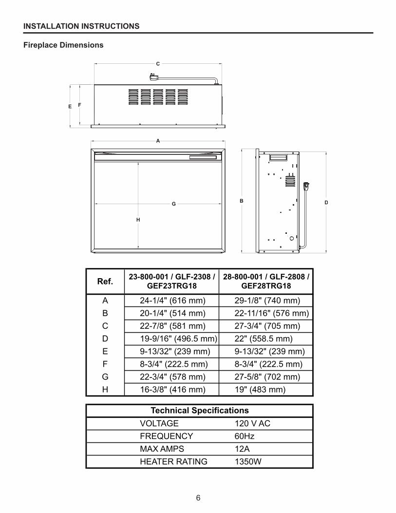
Fireplace Dimensions
Ref.
A 24-1/4" (616 mm) 29-1/8" (740 mm)
B 20-1/4" (514 mm) 22-11/16" (576 mm)
C 22-7/8" (581 mm) 27-3/4" (705 mm)
D 19-9/16" (496.5 mm) 22" (558.5 mm)
E 9-13/32" (239 mm) 9-13/32" (239 mm)
F 8-3/4" (222.5 mm) 8-3/4" (222.5 mm)
G 22-3/4" (578 mm) 27-5/8" (702 mm)
H 16-3/8" (416 mm) 19" (483 mm)
VOLTAGE 120 V AC
FREQUENCY 60Hz
MAX AMPS 12A
HEATER RATING 1350W
Technical Specifications
23-800-001 / GLF-2308 /
GEF23TRG18
28-800-001 / GLF-2808 /
GEF28TRG18
7
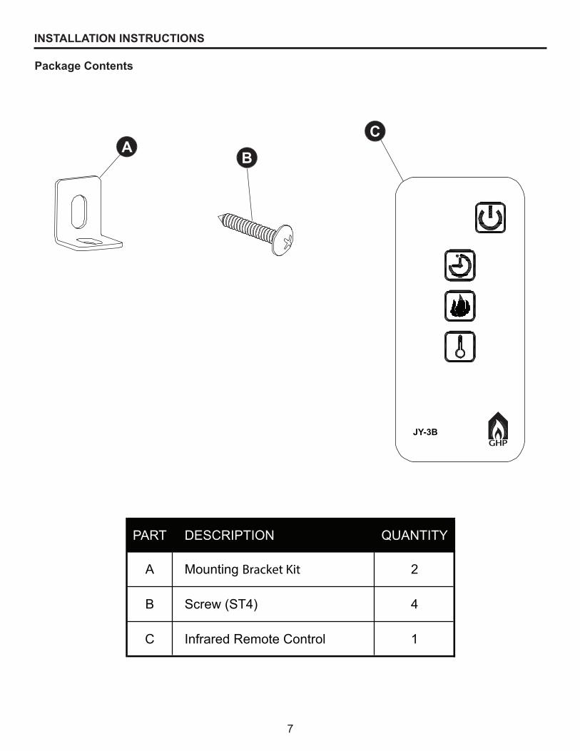
INSTALLATION INSTRUCTIONS
Package Contents
PART DESCRIPTION QUANTITY
A Mounting Bracket Kit 2
B Screw (ST4) 4
C Infrared Remote Control 1
JY-3B
AB
C

8
Clearance to Combustibles
Sides 2-27/64 in. (61.5 mm)
Floor 0 in. (0 mm)
Top 2 in. (51 mm)
Front 36 in. (914 mm)
Rear 25/32 in. (20 mm)
Wooden Facing 5/16 in. (8 mm) [up to 5/8 in. (16 mm) thick]
• Outofdirectsunlight• Notsusceptibletomoisture• Awayfromuninsulatedoutsidewall• Atleast3ft.(.9m)fromdrapery,furnitureandothercombustibles
The Fireplace should be located in an area:
INSTALLATION INSTRUCTIONS
Open the unit and check carefully for visible damage. If you have any problems with installation, operation, missing parts, or damage,please call 877-447-4768 for service.DO NOT dispose of packaging until you are satisfied with your fireplace. DO NOT return unit to store before calling 877-447-4768 for service.
PREPARATIONBefore beginning assembly of product, make sure all parts are present. Compare parts with package contents list and hardware contents. If any part is missing or damaged, do not attempt to assemble the product. Contact customer service for replacement parts.
Estimated Assembly Time: 15 minutesPhillips Screwdriver (not included)

9
INSTALLATION INSTRUCTIONS
1. Place the assembled mantel near a 15-amp, 120-volt grounded electric outlet. Read all instructions before using this appliance.
2. Place the insert directly in front of the mantel opening.3. Carefullylifttheinsertthroughthecenteropeninginthefrontofthefireplace.Thebottomofthe
insert has two foam rubber strips to prevent scratching of the hearth base. Slide the insert back through the opening until the metal trim makes contact with the front of the mantel.
4. Install the mounting brackets provided with the insert in the pre-drilled holes on the bottom of the insert (see Figure 2).
5. Carefullypositionmantelwithinstalledfireplaceagainstwall.6. Plug the power cord into the 15-amp, 120-volt outlet. Use an extension cord rated for a minimum
of 1,875 watts if necessary.
CAUTION: Make sure that the unit is installed so that the power cord is not compressed against or caught on the unit or the mantel and that it has an unobstructed path to the grounded outlet.
NOTE: This unit comes equipped with a safety switch on the back panel which disables the heater (See Figure 3). To enable the heater, please ensure the switch is in the “On” mode. The heater will function using the remote control or control panel on the front of the unit.
Infrared Remote Control
Mounting Brackets
Figure 2Figure 3
Enable Heater/Calefacción habilitada/Chauffage activé
Disable Heater/Calefacción deshabilitada/Chauffage désactivé
10
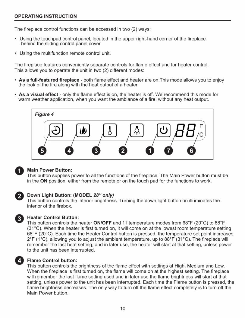
OPERATING INSTRUCTION
Thefireplacefeaturesconvenientlyseparatecontrolsforflameeffectandforheatercontrol.This allows you to operate the unit in two (2) different modes:
• As a full-featured fireplace-bothflameeffectandheaterareon.Thismodeallowsyoutoenjoythelookofthefirealongwiththeheatoutputofaheater.
• As a visual effect-onlytheflameeffectison,theheaterisoff.Werecommendthismodeforwarmweatherapplication,whenyouwanttheambianceofafire,withoutanyheatoutput.
Thefireplacecontrolfunctionscanbeaccessedintwo(2)ways:
• Usingthetouchpadcontrolpanel,locatedintheupperright-handcornerofthefireplace behind the sliding control panel cover.
• Usingthemultifunctionremotecontrolunit.
1
4
2
3
Figure 4
1 7 62345
Main Power Button:Thisbuttonsuppliespowertoallthefunctionsofthefireplace.TheMainPowerbuttonmustbein the ON position, either from the remote or on the touch pad for the functions to work.
Down Light Button: (MODEL 28” only)This button controls the interior brightness. Turning the down light button on illuminates the interiorofthefirebox.
Heater Control Button:This button controls the heater ON/OFF and 11 temperature modes from 68°F (20°C) to 88°F (31°C).Whentheheaterisfirstturnedon,itwillcomeonatthelowestroomtemperaturesetting68°F (20°C). Each time the Heater Control button is pressed, the temperature set point increases 2°F(1°C),allowingyoutoadjusttheambienttemperature,upto88°F(31°C).Thefireplacewillremember the last heat setting, and in later use, the heater will start at that setting, unless power to the unit has been interrupted.
Flame Control button:ThisbuttoncontrolsthebrightnessoftheflameeffectwithsettingsatHigh,MediumandLow.Whenthefireplaceisfirstturnedon,theflamewillcomeonatthehighestsetting.Thefireplacewillrememberthelastflamesettingusedandinlaterusetheflamebrightnesswillstartatthatsetting, unless power to the unit has been interrupted. Each time the Flame button is pressed, the flamebrightnessdecreases.TheonlywaytoturnofftheflameeffectcompletelyistoturnofftheMain Power button.

11
OPERATING INSTRUCTION
5
6
7
Timer Button:This button controls the timer ON/OFF and 10-time setting from 30 minutes to 9 hours. When the Timerisfirstturnedon,itwillcomeonattheshortesttimesetting(30minutes).EachtimetheTimer button is pressed, the time increases 1 hour, up to the longest setting (9 hours). Once the settimeexpires,allfireplacefunctionswillbeautomaticallyturnedoff.
Fahrenheit/Celsius Display:This button displays F (Fahrenheit) or C (Celsius) depending on how the temperature mode is set. Whenthefireplaceisfirstturnedon,theFahrenheit(F)temperaturewillbedisplayed.Toswitchfrom Fahrenheit to Celsius, or vise-versa, when HEATER is ON, hold HEATER CONTROL button for10seconds.Thefireplacewillrememberthelasttemperaturemodesetting,andinlateruse,the display will start at that setting, unless power to the unit has been interrupted.
Temperature/Timer DisplayThis LED display shows the set point for the temperature and timer functions. When either of thesefunctionsisactivated,thedisplayreflectsthesetpointforfivesecondsandthenfadestoblack. Any change in the set point of the temperature or timer will reactivate the display, which againfadesafterfiveseconds.
Theinfraredremotecontrolreliesonalineofsightandmustbepointedattheflame/screenofthefireplacetowork.TheremotecontrolunithasthecontrolsrequiredtoturnON/OFF both the main powerandtheheater.Ifyouprefertousethetouchpadcontrolonthefireplaceunititself,openthecontrol panel sliding cover to access the touchpad buttons.The layout of the buttons on touchpads and remote control unit can be seen in Figures 4 and 6, respectively.
1.Plugyourfireplaceintoa15-amp,120-voltpoweroutlet.2. Turn the power on. Flame will show on the back screen ofthefireplace.
3. Remove plastic tab from inside battery compartment to activate remote control.
4.Pointtheremotecontroldirectlyatthefireplace flame/screenandusethebuttonstooperatethe fireplace.
The plastic tab inside the batterycompartment MUST be removed before remote control will operate.
Figure 5
(Pull tab)
Battery Replacement Procedure: (Size CR2025)
Battery replacement instructionInstructions de remplacement des pilesInstrucción de reemplazo de la batería
CR2025
OPEN
POUSSEREMPUJE
RELÂCHERLIBERAR
OUVRIRABRIR
PUSH
RELEASE

12
Main Power Button: This button supplies power to all the functions of the fireplace.ThemainpowerbuttonmustbeintheON position, either from the remote or on the touch pad for the functions to work.
Timer Button:This button controls the timer ON/OFF and 10-time setting from30minutesto9hours.WhentheTimerisfirstturnedon, it will come on at the shortest time setting (30 minutes). Each time the Timer button is pressed, the time increases 1 hour, up to the longest setting (9 hours). Once the set time expires,allfireplacefunctionswillbeautomaticallyturnedoff.
Flame Control button: ThisbuttoncontrolsthebrightnessoftheflameeffectwithsettingsatHigh,MediumandLow.Whenthefireplaceisfirstturnedon,theflamewillcomeonatthehighestsetting.Thefireplacewillrememberthelastflamesettingusedandinlaterusetheflamebrightnesswillstartatthatsetting,unlesspower to the unit has been interrupted. Each time the Flame buttonispressed,theflamebrightnessdecreases.TheonlywaytoturnofftheflameeffectcompletelyistoturnofftheMain Power button.
Heater Control Button:This button controls the heater ON/OFF and 11 temperature modes from 68°F (20°C) to 88°F (31°C). When the heater is firstturnedon,itwillcomeonatthelowestroomtemperaturesetting 68°F (20°C). Each time the Heater Control button is pressed, the temperature set point increases 2°F (1°C), allowing you to adjust the ambient temperature, up to 88°F (31°C).Thefireplacewillrememberthelastheatsetting,andin later use, the heater will start at that setting, unless power to the unit has been interrupted.
NOTE: To switch between Fahrenheit/Celsius modes see control panel Fahrenheit/Celsius display instructions.
OPERATING INSTRUCTION
1
2
3
4
Figure 6
234
1

13
CARE AND MAINTENANCE
Glass Information:
Maintenance of Motors:
Cleaning:
Before attempting ANY maintenance:1. Turn off power to the unit.2. Unplug the power cord from outlet.3. Letfireplacecoolifithasbeenoperating.
1. Under no circumstances should this product be operated with broken glass.2. Do not strike or slam the glass.3. Do not use abrasive cleaners to clean the glass.4. This product uses tempered glass. Replacement of the glass supplied by the manufacturer shouldbedonebyaqualifiedserviceperson.
Always disconnect the appliance from the main power supply and allow it to cool before any servicing operation. Themotorsusedonthefanheaterandflameblowerarepre-lubricatedforextendedbearinglifeandrequire no further lubrication. However, periodic cleaning/vacuuming of the appliance around the air intake and exhaust, as well as the fan heater is recommended. For heavy or continuous use, periodic cleaning must be done more frequently. If the heater blows alternating cold and warm air, check the fanforfreemovementandfordebrisrestrictingairflow.Ifthefandoesnotmovefreely,theunitmustbe turned off and the fan replaced immediately in order to prevent further damage to the unit.
Cleaningofthecontrolpanel,locatedintheupperright-handcornerofthefireplacebehindthesliding control panel cover, is to be done only using a soft cloth, slightly dampened in water (if needed, a small amount of dish soap can be added to the water) and dried using a clean, dry soft cloth. Cleaning of the screen diffuser is to be done using only water and a lint free cloth. DO NOT use any abrasive household cleaners as these products will damage the touch-padcontrols and the diffusing screen.

14
Disconnect power before servicing.
Anyelectricalre-wiringofthisappliancemustbedonebyaqualifiedelectrician.This wiring must be done in accordance with local codes and/or in Canada with the current CSA C22.1 Canadian Electrical Code, and for US installations, the National Electrical Code ANSI/NFPA NO 70.
If repairing or replacing any electrical component or wiring, the original wire routing, color coding and securing locations must be followed.
DANGER
Any electrical repairs or rewiring of this unit should be carried out by a licensed electrician in accordance with national and local codes.
ELECTRIC WIRING DIAGRAM
CIRCUIT DIAGRAM
WARNING: Disconnect power before servicing.

15
TROUBLESHOOTING
If you have any questions regarding the product, please call customer service at 877-447-4768 8:30 a.m. – 4:30 p.m. CST, Monday – Friday.
Problem Possible Cause Corrective Action
Fireplace does not operate; the ON/OFF power light on the control panel is not lit.
Power light is ON butthebackflame is not bright/visible.
Power light is ON but the ember bed flameisnot flickering.
Excessive noise whentheflameisON but the heater OFF.
Excessive noise when the heater is operating.
Heater is not operating.
1.Thefireplaceisnot plugged in.
2. A circuit breaker is tripped or a fuse blown.
3. Defective ON/OFF switch.
4. Loose wiring.
1. Incorrect operation.
2. LED strip not functioning.
3. Loose wiring.
1. LED strip not functioning.
2. Loose wiring.
1.Rotatingflamereflector shaft rubbing against housing.
2.Defectiveflamereflector shaft motor.
1. Dirty or clogged blower.
2. Defective heater assembly.
1. Incorrect operation.2. Safety switch enabled3. Defective heater switch.
4. Defective heater assembly.5. Loose wiring.6. Dirty or clogged sliding door.
7. Thermostat has been satisfied
1.Makesurethefireplaceispluggedin toastandard120Voutlet.
2. Check additional appliances on the circuit;ideallythefireplaceshouldbe on a dedicated 15-amp circuit.
3. Call customer service: (877) 447-4768.
4. Call customer service: (877) 447-4768.
1. Refer to operating instructions.
2. Call customer service: (877) 447-4768.
3. Call customer service: (877) 447-4768.
1. Call customer service: (877) 447-4768.
2. Call customer service: (877) 447-4768.
1.Openbackoffireboxandrepositionflamereflectorshaft.Turnoffunitprior to servicing.
2. Call customer service: (877) 447-4768.
1. Refer to Maintenance of Motors in Care and Maintenance.
2. Call customer service: (877) 447-4768.
1. Refer to operating instructions.2. Ensure switch is in "ON" position (see pg 9)3. Call customer service: (877) 447-4768.4. Call customer service: (877) 447-4768.5. Call customer service: (877) 447-4768.6. Unplug the unit. Clear door area of dust anddebris.Waitfiveminutes,plugtheunit in again and turn on the heater.
7. Increase desired room temperature on the control panel/remote

16
Themanufacturerwarrantsthatyournewelectricfireplaceisfreefrommanufacturingandmaterial defects for a period of one year from date of purchase, subject to the following conditions and limitations.1. Thiselectricfireplacemustbeinstalledandoperatedatalltimesinaccordancewiththe
instructions furnished with the product. Any alteration, willful abuse, accident, or misuse of the product shall nullify this warranty.
2. This warranty is non-transferrable, and is made to the original owner, provided that the purchase wasmadethroughanauthorizedsupplierofthemanufacturer.
3. This warranty is limited to the repair or replacement of part(s) found to be defective in material or workmanship, provided that such part(s) have been subjected to normal conditions of use and service,aftersaiddefectisconfirmedbythemanufacturer’sinspection.
4. The manufacturer may, at its discretion, fully discharge all obligations with respect to this warranty by refunding the wholesale price of the defective part(s).
5. Any installation, labor, construction, transportation, or other related costs/expenses arising from defective part(s), repair, replacement, or otherwise of same, will not be covered by this warranty, nor shall the manufacturer assume responsibility for same. Further, the manufacturer will not be responsible for any incidental, indirect, or consequential damages, except as provided by law.
6. All other warranties - expressed or implied - with respect to the product, its components and accessories, or any obligations/liabilities on the part of the manufacturer are hereby expressly excluded.
7. Themanufacturerneitherassumes,norauthorizesanythirdpartytoassume,onitsbehalf, any other liabilities with respect to the sale of this product.
8. The warranties as outlined within this document do not apply to non-manufacturer accessories used in conjunction with the installation of this product.
This warranty is void if:a) Thefireplacehasbeenoperatedinatmospherescontaminatedbychlorine,fluorineorother damaging chemicals.b)Thefireplaceissubjectedtoprolongedperiodsofdampnessorcondensation.c) Any alteration, willful abuse, accident, or misuse of the product.
IF WARRANTY SERVICE IS NEEDED . . .1) Contact customer service. Make sure you have your warranty, your sales receipt, and the model/serial number of your product.2)DONOTATTEMPTTODOANYSERVICEWORKYOURSELF.
WARRANTY
GHP Group, Inc.6440 W. Howard St.Niles, IL 60714-3302877-447-4768
17
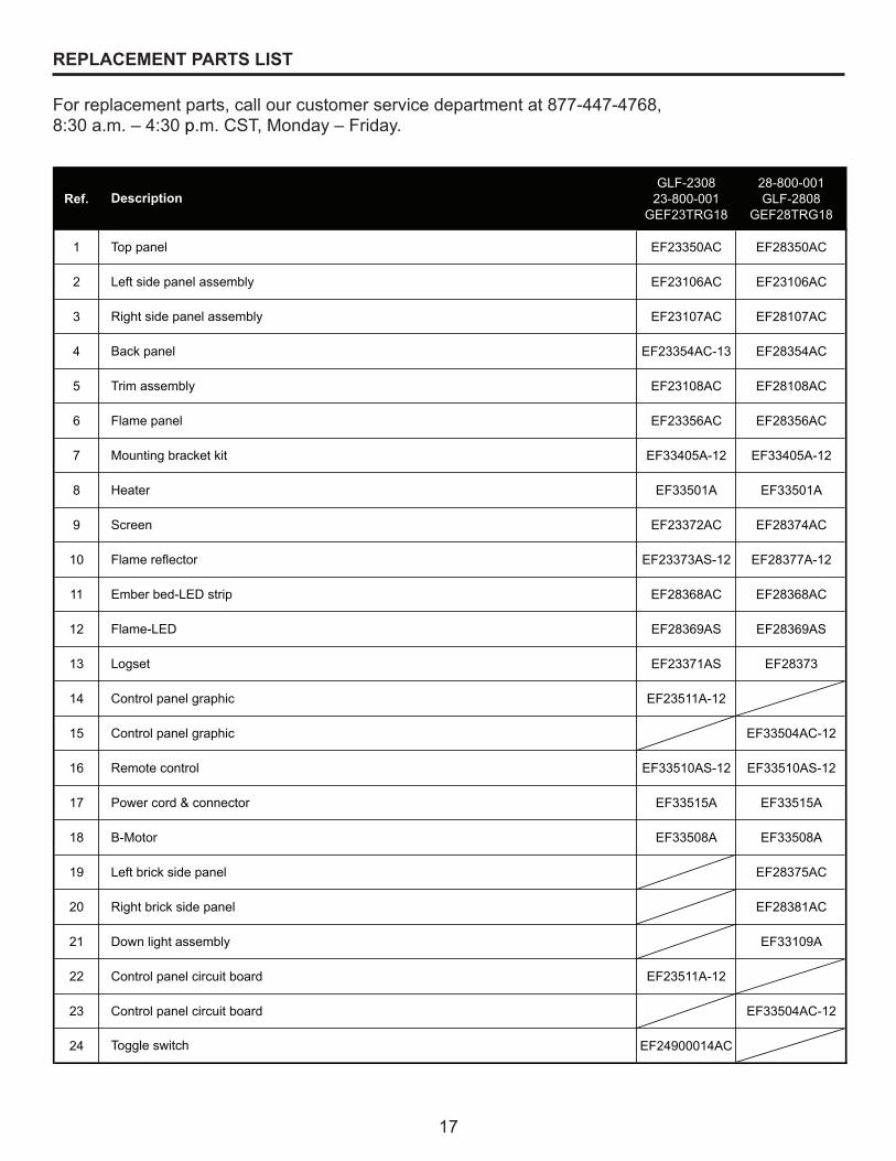
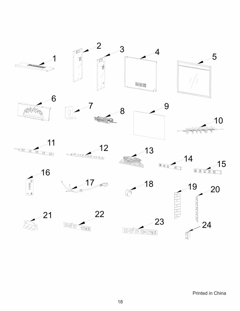
REPLACEMENT PARTS LIST
For replacement parts, call our customer service department at 877-447-4768, 8:30 a.m. – 4:30 p.m. CST, Monday – Friday.
Ref.GLF-2308
23-800-001GEF23TRG18
28-800-001GLF-2808
GEF28TRG18
1 EF23350AC EF28350AC
2 EF23106AC EF23106AC
3 EF23107AC EF28107AC
4 EF23354AC-13 EF28354AC
5 EF23108AC EF28108AC
6 EF23356AC EF28356AC
7 EF33405A-12 EF33405A-12
8 EF33501A EF33501A
9 EF23372AC EF28374AC
10 EF23373AS-12 EF28377A-12
11 EF28368AC EF28368AC
12 EF28369AS EF28369AS
13 EF23371AS EF28373
14 EF23511A-12
15 EF33504AC-12
16 EF33510AS-12 EF33510AS-12
17 EF33515A EF33515A
18 EF33508A EF33508A
19 EF28375AC
20 EF28381AC
21 EF33109A
22 EF23511A-12
23 EF33504AC-12
24 EF24900014AC
Control panel circuit board
Control panel circuit board
Toggle switch
Screen
Left side panel assembly
Left brick side panel
Remote control
Control panel graphic
Control panel graphic
Power cord & connector
B-Motor
Description
Top panel
Trim assembly
Flame panel
Mounting bracket kit
Heater
Right side panel assembly
Back panel
Right brick side panel
Down light assembly
Flame reflector
Ember bed-LED strip
Flame-LED
Logset
18
Printed in China
14 15
1
6
11 12 13
1617 18 19 20
21
7 8 9
10
2 3 4 5
2322
24

19
Des questions, des problèmes, des pièces manquantes? Avant de retournerl’articleaudétaillant,appeleznotreserviceàlaclientèleau8774474768,
entre8h30et16h30,HNC,dulundiauvendredi,ouenvoyez-nousuncourrielàl’adressesuivante:[email protected].
DIRECTIVES D’INSTALLATION ET D’UTILISATION
À installer avec le manteau pour foyer Pleasant Hearth.
C US
REMARQUE À L’INTENTION DE L’INSTALLATEUR : Veuillez laisser ce manuel au propriétaire.REMARQUE À L’INTENTION DU CLIENT : Veuillez conserver ce manuel pour vous
y référer ultérieurement.
AVERTISSEMENT!RESPECTEZ SCRUPULEUSEMENT LES DIRECTIVES DU PRÉSENT MANUEL
POUR PRÉVENIR LES CHOCS ÉLECTRIQUES, LES INCENDIES, LES DOMMAGES AINSI QUE LES BLESSURES GRAVES OU MORTELLES.
CONSIGNES IMPORTANTESVEUILLEZ LIRE CE MANUEL AVANT D’INSTALLER OU D’UTILISER LE FOYER.
FOYER ÉLECTRIQUE ENCASTRABLE PLEASANT HEARTHMODÈLE Nº ##GLF-2308 / 23-800-001 / GEF23TRG18/
28-800-001 / GLF-2808 / GEF28TRG18
FRANCÁIS
20-10-171 Rev. 4/13
6440 W. Howard St.Niles, IL 60714-3302
877-447-4768
20
IMPORTANT : Lisez attentivement toutes les directives et les avertissements avant de procéder à l’installation. Le non-respect de ces directives peut provoquer un choc électrique, des blessures et un incendie, et annule la garantie.
Veuillez lire les directives d’installation et d’utilisation avant d’utiliser ce foyer.
TABLE DE MATIÉRES
Consignesdesécurité .................................................................................................................... 21
Directivesd’installation ................................................................................................................... 25
Directivesd’utilisation ..................................................................................................................... 29
Entretien ......................................................................................................................................... 32
Schémadecâblage ........................................................................................................................ 33
Dépannage ..................................................................................................................................... 34
Garantie .......................................................................................................................................... 36
Liste des pièces de rechange ......................................................................................................... 37
Merci et félicitations pour votre achat d’un foyerélectrique de GHP Group.

21
Veuillezvousassurerdelireetdecomprendrel’intégralitédecemanuelavantd’assembler,d’utiliseroud’installerceproduit.Sivousavezdesquestionsconcernantceproduit,veuilleztéléphonerauserviceàlaclientèleau1-877-447-4768,entre8h30et16h30,HNC,dulundiauvendredi.
1. Liseztouteslesdirectivesavantd’utilisercefoyer.
2. Cefoyerestchaudlorsqu’ilestenfonction.Afind’éviterlesbrûlures,netouchezpasaux surfaceschaudes.Silefoyerestmunidepoignées,servez-vousdespoignéespourle déplacer.Assurez-vousquelesmatièrescombustibles,telsquelesmeubles,lesoreillers, la literie, le papier, les vêtements et les rideaux, se trouvent au moins 914 mm (3 pi) del’avantdufoyer.
3. MISE EN GARDE : Faites preuve d’une extrême prudence lorsqu’un radiateur est utilisé par ou à proximité des enfants ou des personnes handicapées et lorsque vous laissez le radiateur en fonction sans surveillance.
4. Danslamesuredupossible,débrancheztoujourscefoyerlorsqu’iln’estpasutilisé.
5. N’utilisezpasunradiateurmunid’uncordonoud’uneficheendommagé,quiadéjàsubiunedéfaillance,quiestdéjàtombéouquiaétéendommagédequelquefaçonquecesoit.
6. Confieztouteréparationdecefoyeràuntechnicienqualifié.
7. Nemodifiezjamaiscefoyer.Remettezenplacelespiècesquidoiventêtreretiréespourl’entretienavantd’utiliserlefoyerdenouveau.
8. N’utilisezpascefoyeràl’extérieur.
9. Leradiateurn’estpasconçupourêtreutilisédansunesalledebains,unesalledelavageoutoutautreendroithumidesemblable.Neplacezjamaiscefoyerenunendroitoùilpourraittomberdansunebaignoireouunautrecontenantremplid’eau..
10. Évitezd’acheminerlecordonsousuntapis.Necouvrezpaslecordonavecunecarpette,untapisdepassageouunautrearticlesemblable.Placezlecordondansunendroitpeupassantetoùilnepourrapasêtreaccroché.
11. Pourdébranchercefoyer,tournezlescommandesenpositiond’arrêt,puisretirezlafiche de la prise.
12. Branchezlecordonuniquementàuneprisecorrectementmiseàlaterre.
13. Lorsdel’installation,veillezàcequelefoyersoitmisàlaterreconformémentauxcodeslocaux,àlaplusrécenteversionduCodecanadiendel’électricité,CSAC22.1ou,danslecasdes installationsauxÉ.-U.,auxcodeslocauxetaucodenationaldel’électricité,ANSI/NFPANº70.
14. N’insérezjamaisunobjet,quelqu’ilsoit,danslesouverturesdeventilationoudesortied’air dufoyerafindeprévenirlesdommagesainsiquelesrisquesdechocélectriqueetd’incendie.
15. Afindeprévenirlesrisquesd’incendie,nebloquezjamaislesprisesd’entréeoudesortied’airdequelquefaçonquecesoit.Neplacezpaslefoyersurunesurfacemolle,commeunlit,carles ouvertures pourraient se bloquer.
CONSIGNES DE SÉCURITÉ CONSERVEZ CES DIRECTIVES

22
16. Cefoyerrenfermedespièceschaudesetquiproduisentdesarcsélectriquesoudesétincelles.N’utilisezpaslefoyerlàoùdel’essence,delapeintureoudesliquidesinflammablessont utilisésouentreposés.CefoyeretsesenvironsnedoiventpasservirdesupportdeséchagepourlesvêtementsniàaccrocherdesbasdeNoëloudesdécorations.
17. N’utilisezcefoyerquepourl’usageprévudanscemanuel.Touteautreutilisationdufoyerquin’estpasprévueparlefabricantpeutprovoquerunincendie,unchocélectriqueoudesblessures.
18. Évitezd’utiliserunerallongecarellepourraitsurchaufferetprésenterdesrisquesd’incendie.Lesrallongesneserventqu’àunusagetemporaire.Siunerallongedoitêtreutilisée,assurez-vousqu’ils’agitd’unerallongecertifiéeUL/CSAd’uneintensiténominalede15A(1875watts),125Vmaximum,d’uncalibreaméricaindesfilsminimalde14etdotéededeuxconducteursdecourantetd’unemiseàlaterre.Nousvousrecommandonsd’utiliserunerallongerobusteaussicourtequepossible,d’auplus15,2m(50pi).N’enroulezpaslarallongeetnelacouvrezpas.
CONSIGNES DE SÉCURITÉ
CONSERVEZ CES DIRECTIVES

23
BROCHE DE MISE À LA
TERRE
COSSE DE MISE À LA
TERRE
VIS MÉTALLIQUE
BROCHE DE MISE À LA
TERRE
COUVERCLE DE LA BOÎTE DE SORTIE
MISE À LA TERRE
ADAPTATEUR
(A) (B)
(C)
(D)
Figure 1
CONSIGNES DE SÉCURITÉ
Branchement électrique
Directives de mise à la terre
Uncircuitde15A,120V,60Hzcorrectementmisàlaterreestnécessaire.Ilestrecommandéderéserveruncircuitaufoyercard’autresappareilsalimentésparlemêmecircuitpourraientcauserledéclenchementdudisjoncteuroufairegrillerle fusiblelorsqueleradiateurestenfonction.Lefoyerestmunid’uncordontrifilairede1,8m(6pi)quisetrouveducôtédroitdufoyer.Planifiezl’installationpouréviterd’utiliserunerallonge.Lesrallongesneserventqu’àunusagetemporaire.Siune rallongedoitêtreutilisée,assurez-vousqu’ils’agitd’unerallongecertifiéeUL/CSAd’uneintensiténominalede15A(1875watts),125Vmaximum,d’uncalibre américaindesfilsminimalde14etdotéededeuxconducteursdecourantetd’unemiseàlaterre.Nousvousrecommandonsd’utiliserunerallongeaussicourtequepossible,d’auplus15,2m(50pi).N’enroulezpaslarallongeetnelacouvrezpas.
Lecâblagedelapriseélectriquedoitêtreconformeauxcodesdubâtimentlocauxetàtoutautrerèglementafinderéduirelerisqued’incendie,dechocélectriqueoudeblessure.
N’utilisezpascefoyersiunepartiedufoyeraétéimmergée.Appelez immédiatementuntechnicienqualifiéquiinspecteralefoyeretremplaceratoutepartieducircuitélectriquequiaétéimmergée.
Ceradiateurestconçuenfonctiond’uncircuitde120volts.Lecordonestdoté d’unefiche(illustrationA,figure1).Unadaptateur(illustrationC,figure1)permet debrancherlesfichesàtroisbrochesavecmiseàlaterreauxprisesàdeuxfentes.Lacossedemiseàlaterrevertedel’adaptateurdoitêtrebranchéeàunemiseàlaterrepermanentecommeuneboîtedesortiecorrectementmiseàlaterre.Nevousservezpasdel’adaptateursiunepriseàtroisfentesmiseàlaterreestdisponible.
DANGER
Avertissement: N’utilisez PAS d’adaptateurs au Canada.
24
CONSIGNES DE SÉCURITÉ
Télécommande
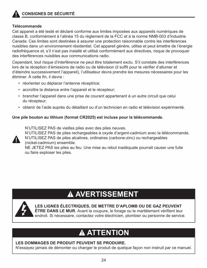
LES LIGNES ÉLECTRIQUES, DE METTRE D’APLOMB OU DE GAZ PEUVENT ÊTRE DANS LE MUR. Avantlacoupure,leforageoulemartèlementvérifientleur endroit.Sinécessaire,contactezvotreélectricien,plombieroupersonnedeservice.
LES DOMMAGES DE PRODUIT PEUVENT SE PRODUIRE. N’essayezjamaisdedémonterouchangerleproduitdequelquefaçonnoninstruitparcemanuel.
CetappareilaététestéetdéclaréconformeauxlimitesimposéesauxappareilsnumériquesdeclasseB,conformémentàl’alinéa15durèglementdelaFCCetàlanormeNMB-003d’IndustrieCanada.Ceslimitessontdestinéesàassureruneprotectionraisonnablecontrelesinterférencesnuisiblesdansunenvironnementrésidentiel.Cetappareilgénère,utiliseetpeutémettredel’énergieradiofréquenceet,s’iln’estpasinstalléetutiliséconformémentauxdirectives,risquedeprovoquerdesinterférencesnuisiblesauxcommunicationsradio.Cependant,toutrisqued’interférencenepeutêtretotalementexclu.S’ilconstatedesinterférenceslorsdelaréceptiond’émissionsderadiooudetélévision(ilsuffitpourlevérifierd’allumeretd’éteindresuccessivementl’appareil),l’utilisateurdevraprendrelesmesuresnécessairespourleséliminer.Àcettefin,ildevra: • réorienteroudéplacerl’antenneréceptrice; • accroîtreladistanceentrel’appareiletlerécepteur; • brancherl’appareildansuneprisedecourantappartenantàunautrecircuitquecelui durécepteur; • obtenirdel’aideauprèsdudétaillantoud’untechnicienenradioettélévisionexpérimenté.
Une pile bouton au lithium (format CR2025) est incluse pour la télécommande.
N’UTILISEZPASdevieillespilesavecdespilesneuves.N’UTILISEZPASdepilesrechargeablesàoxyded’argent-cadmiumaveclatélécommande.N’UTILISEZPASdepilesalcalines,ordinaires(carbone-zinc)ourechargeables (nickel-cadmium) ensemble. NEJETEZPASlespilesaufeu.Unemiseaurebutinadéquatepourraitcauserunefuite ou faire exploser les piles.
AVERTISSEMENT
ATTENTION

25
DIRECTIVES D’INSTALLATION
Dimensions du foyer
Réf.
A 616 mm 740 mm
B 514 mm 576 mm
C 581 mm 705 mm
D 496.5 mm 558.5 mm
E 239 mm 239 mm
F 222.5 mm 222.5 mm
G 578 mm 702 mm
H 416 mm 483 mm
120 V AC
60Hz
12A
1350W
23-800-001 / GLF-2308 /
GEF23TRG18
28-800-001 / GLF-2808 /
GEF28TRG18
Fiche technique
Tension
Fréquence
Intensité Maximale
Puissance Nominale
du Radiateur

26
DIRECTIVES D’INSTALLATION
Contenu de l'emballage
PIÈCE DESCRIPTION QUANTITÉ
A Ensemble de supports de fixation 2
B Vis (ST4) 4
C Télécommande à infrarouge 1
JY-3B
AB
C

27
�����������
Dégagement minimal avec les matières combustibles
Côtés 61.5mm
Plancher 0 mm
Dessus 51 mm
Avant 914 mm
Arrière 20 mm
Le Revêtement en bois 8 mm [augmenteà16mmépais]
• quin’estpasexposéàlalumièredirectedusoleil;•quin’estpasexposéàl’humidité;•àl’écartdesmursextérieursnonisolés;•àaumoins0,9m(3pi)desrideaux,desmeublesetdetouteautrematièrecombustible.
Placez le foyer en un endroit :
DIRECTIVES D’INSTALLATION
Ouvrezlefoyeretvérifiezsoigneusements’ilestendommagé.Encasdeproblèmesd’installation,d’utilisation,depiècesmanquantesoudedommages,communiquezavecleserviceàlaclientèle au 877 447-4768.NE JETEZ PAS l’emballage tant que vous n’êtes pas satisfait de votre foyer. NE RETOURNEZ PAS le foyer au détaillant avant de communiquer avec le service à la clientèle au numéro sans frais 877 447-4768.
PRÉPARATIONAvantdecommencerl’assemblageduproduit,assurez-vousd’avoirtouteslespièces.Comparez lespiècesaveclalisteducontenudel’emballageetdelaquincaillerieci-dessus.S’ilyadespieces manquantesouendommagées,netentezpasd’assemblerleproduit.Communiquezavecleservice àlaclientèlepourobtenirdespiècesderechange.
Temps d’assemblage approximatif: 15 minutestournevis cruciforme (non inclus)

28
REMARQUE : Assurez-vous que le foyer est installé de sorte que le cordon d’alimentation ne soit pas comprimé ou pincé sous l’unité ou le manteau et que la voie soit libre vers la prise mise à la terre.
DIRECTIVES D’INSTALLATION
1. PlacezlemanteauenboisPleasantHearthassembléprèsd’uneprisede15A,120Vmise àlaterre.Liseztouteslesdirectivesavantd’utilisercefoyer.
2.Placezlefoyerencastrabledirectementàl’avantdel’ouverturedumanteau.3.Levezsoigneusementlefoyerencastrabledanslecentredel’ouvertureàl’avantdufoyer.
Ilyadeuxcaoutchoucsenbandesurlapartieinférieuredufoyer-insertquiprotègentl’âtre deségratignures.Glissezlefoyerencasqtrabledansl’ouverturejusqu’àcequelagarniture métalliquetoucheàl’avantdumanteau.
4.Installezlessupportsdemontagefournisaveclefoyerencastrabledanslestrouspréperforés surlefonddufoyerencastrable(voirlafigure2).
5.Placezsoigneusementlemanteau,lefoyeryétantinstallé,contrelemur.6.Branchezlecordond’alimentationdanslaprisede15A,120V.Utilisezunerallonged’une
puissance minimale de 1 875 watts au besoin.
NOTE:Ilyauninterrupteurdesécuritéàl’arrièredecettechaufferettequipermetdel’éteindre(voirlafigure3).Veuillez-vousassurerquel'interrupteurestàlaposition« ON »sivousvoulezutiliser la chaufferette. Utilisezlatélécommandeoulepanneaudecommandefrontal pour faire fonctionner la chaufferette
Télécommandeàinfrarouge
Supports de montage
Figure 2Figure 3
Enable Heater/Calefacción habilitada/Chauffage activé
Disable Heater/Calefacción deshabilitada/Chauffage désactivé

29
DIRECTIVES D’UTILISATION
Lefoyercomprenddepratiquescommandesdistinctespourl’effetdeflammeetleradiateur.Cescommandespermettentd’utiliserlefoyerendeux(2)différentsmodes:• Comme foyer complet–l’effetdeflammeetleradiateursontenfonction.Cemodepermet d’apprécierl’apparenced’unfeutoutenbénéficiantdel’apportdechaleurd’unradiateur.• Comme effet visuel seulement–seull’effetdeflammeestenfonction,leradiateuresthors fonction.Nousrecommandonscemodelorsquelatempératureestélevée,pourapprécier l’ambianced’unfeusansapportdechaleur.
Deux(2)méthodespermettentd’accéderauxfonctions de commande du foyer :•Aumoyendutableaudecommandetactile,danslecoinsupérieurdroitdufoyerderrièrele couvercle coulissant du panneau de commande.• aumoyendelatélécommandemultifonction.
1
2
3
Interrupteur général :Ceboutonfournitl’énergieàtouteslesfonctionsdelacheminée.Pourquecesfonctionstravaillent,leBoutonPrincipald’Allumagedoitêtredanslaposition“ON”(d’allumage),soitàpartirdelatélécommandeousurlepavétactiledelacheminée.
Bouton du luminaire à éclairage direct: (MODÈLE de 71,12 cm seulement) Ceboutonpermetderéglerl’intensitédel’éclairagedufoyer.Allumezleboutond’éclairageilluminel’intérieurdelachambredecombustion. Bouton de réglage de l’appareil de chauffage:C’estleboutonMarche/Arrêtetleboutonquipermetderéglerlatempératurede20°C (68°F) à31°C (88°F)-11réglages.L’appareilserarégléàlaplusbassetempératureambiante20°C (68°F)quandonleferafonctionner.Ilyaurauneaugmentationdelatempératurede1°C(2°F)chaquefoisqu’onappuierasurleboutonderéglagedel’appareildechauffage.Vouspourrezainsiajusterlatempératureambiantejusqu’à31°C(88°F).Lefoyersesouviendradeladernièretempératuresélectionnéeetserarégléàcettetempératurelorsdelaprochaineutilisation,àmoinsquelecourantaitétécoupé.
Bouton de commande de flamme:Ceboutondecommandepermetderéglerl’intensitélumineusedesflammes(haute,moyenne,basse).Lesflammesserontàl’intensitélumineusemaximalelorsdelamiseenmarchedufoyer.Lefoyerconserverasonréglagedeflammeenmémoirechaquefoisquevousl'éteindrez,àmoinsd'unecoupuredecourant. Ilestpossibledediminuerl’intensitélumineusedesflammesenappuyantsurcebouton.Seullecommutateurprincipalpermetd’éteindrecomplètementlesflammesartificielles.
Figure 4
1 7 62345
4
30
Latélécommandeàinfrarougedoitsetrouverenvisibilitédirecteaveclaflammeoul’écranpourfonctionner.Lescommandesdelatélécommandepermettentd’établiretdecouperl’alimentationetdemettreleradiateurenfonctionethorsfonction.Sivouspréférezutiliserleclaviertactiledufoyermême,ouvrezlecouverclecoulissantdupanneaudecommandepouraccéderauxboutonsduclaviertactile.Consultezrespectivementlesfigures4et6pourconnaîtreladispositiondesboutonsduclaviertactileetdelatélécommande.
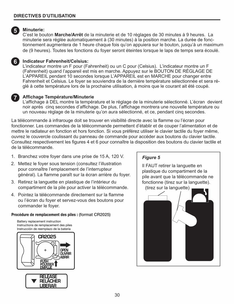
1. Branchezvotrefoyerdansuneprisede15A,120V.2. Mettezlefoyersoustension(consultezl’illustration
pourconnaîtrel’emplacementdel’interrupteur général).Laflammeparaîtsurlaécranarrièredufoyer.
3. Retirezlalanguetteenplastiquedel’intérieurdu compartimentdelapilepouractiverlatélécommande.
4. Pointezlatélécommandedirectementsurlaflamme oul’écrandufoyeretservez-vousdesboutonspourcommander le foyer.
DIRECTIVES D’UTILISATION
Figure 5
Il FAUT retirer la languette en plastique du compartiment de la pileavantquelatélécommandene fonctionne(tirezsurlalanguette).
(tirezsurlalanguette)
5
6
7
Minuterie:C’estleboutonMarche/Arrêtdelaminuterieetde10réglagesde30minutesà9heures.Laminuterieserarégléeautomatiquementà(30minutes)àlapositionmarche.Laduréedefonc-tionnementaugmenterade1heurechaquefoisqu’onappuierasurlebouton,jusqu’àunmaximumde(9heures).Touteslesfonctionsdufoyerserontéteinteslorsquelelapsdetempsseraécoulé.
Indicateur Fahrenheit/Celsius:L’indicateurmontreunFpour(Fahrenheit)ouunCpour(Celsius).L’indicateurmontreunF(Fahrenheit)quandl’appareilestmisenmarche.AppuyezsurleBOUTONDERÉGLAGEDEL’APPAREILpendant10secondeslorsqueL’APPAREILestenMARCHEpourchangerentreFahrenheitetCelsius.Lefoyersesouviendradeladernièretempératuresélectionnéeetseraré-gléàcettetempératurelorsdelaprochaineutilisation,àmoinsquelecourantaitétécoupé.
Affichage Température/MinuterieL’affichageàDELmontrelatempératureetleréglagedelaminuteriesélectionné.L’écrandevientnoiraprèscinqsecondesd’affichage.Deplus,l’affichagemontreraunenouvelletempératureouunnouveauréglagedelaminuteriequ’onaurasélectionné,etce,pendantcinqsecondes.
Procédure de remplacement des piles : (format CR2025)
Battery replacement instructionInstructions de remplacement des pilesInstrucción de reemplazo de la batería
CR2025
OPEN
POUSSEREMPUJE
RELÂCHERLIBERAR
OUVRIRABRIR
PUSH
RELEASE

31
Interrupteur général :Ceboutonfournitl’énergieàtouteslesfonctionsdelacheminée.Pourquecesfonctionstravaillent,leBoutonPrincipald’Allumagedoitêtredanslaposition“ON” (d’allumage),soitàpartirdelatélécommandeousurlepavétactiledelacheminée.
Minuterie:C’estleboutonMarche/Arrêtdelaminuterieetde10ré-glagesde30minutesà9heures.Laminuterieserarégléeautomatiquementà(30minutes)àlapositionmarche.Laduréedefonctionnementaugmenterade1heurechaquefoisqu’onappuierasurlebouton,jusqu’àunmaximumde(9heures).Touteslesfonctionsdufoyerserontéteinteslorsquelelapsdetempsseraécoulé. Bouton de commande de flamme:Ceboutondecommandepermetderéglerl’intensitélumineusedesflammes(haute,moyenne,basse).Lesflammesserontàl’intensitélumineusemaximalelorsdelamise en marche du foyer. Lefoyerconserverasonréglagedeflammeenmémoirechaquefoisquevousl'éteindrez,àmoinsd'unecoupuredecourant.Il est possible de diminuer l’intensitélumineusedesflammesenappuyantsurcebouton.Seullecommutateurprincipalpermetd’éteindrecomplètementlesflammesartificielles.
Bouton de réglage de l’appareil de chauffage:C’estleboutonMarche/Arrêt et le bouton qui permet de réglerlatempératurede20°C(68°F)à31°C(88°F)-11réglages.L’appareilserarégléàlaplusbassetempératureambiante 20°C (68°F) quand on le fera fonctionner. Il y aura uneaugmentationdelatempératurede1°C(2°F)chaquefoisqu’onappuierasurleboutonderéglagedel’appareildechauffage.Vouspourrezainsiajusterlatempératureambiantejusqu’à31°C(88°F).Lefoyersesouviendradeladernièretempératuresélectionnéeetserarégléàcettetempératurelorsdelaprochaineutilisation,àmoinsquelecourantaitétécoupé.
NOTE :ConsultezlesinstructionssurlacommandeFahrenheith/Celciuspourchoisirentrel’affichageFahrenheith ou Celcius.
DIRECTIVES D’UTILISATION
1
2
3
4
Figure 6
234
1

32
ENTRETIEN
Renseignements sur la vitre :
Entretien des moteurs :
Nettoyage :
1. N’utilisezjamaiscefoyersilavitreestbrisée.2. Nefrappezpaslavitreetnelatapezpas.3. Nenettoyezpaslavitreavecunproduitabrasif.4. Cefoyerestmunid’unevitretrempée.Confiezleremplacementdelavitrefournieparlefabricant àuntechnicienqualifié.
Avant TOUT entretien :1. Coupezl’alimentationdufoyer.2. Débranchezlecordond’alimentationdelaprise.3. Laissezlefoyerrefroidirs’ilétaitenfonction.
Débranchez toujours le foyer de l’alimentation électrique principale et laissez le foyer refroidir avant tout entretien. Lesmoteursutiliséssurleradiateurduventilateuretlasoufflantedeflammeontétéprégraisséspourprolongerladuréedesroulementsetn’exigentaucunautregraissage.Ilesttoutefoisrecommandédenettoyerlefoyeretdepasserl’aspirateurpériodiquementautourdelaprised’air,delasortied’airetduradiateurduventilateur.Nettoyezplusfréquemmentlefoyerencasd’utilisationintensiveoucontinue.Sileradiateurpropulseenalternancedel’airfroidetdel’airchaud,vérifiezsileventilateurtournelibrementousidesdébrisobstruentlacirculationd’air.Sileventilateurnetournepaslibrement,mettezlefoyerhorsfonction,puisremplacezimmédiatementleventilateurpourprévenirtoutautredommage au foyer.
Nettoyagedupanneaudecommande,danslecoinsupérieurdroitdufoyerderrièrelecouvercledupanneaudecommandecoulissant,exclusivementavecunchiffondouxlégèrementhumectéd’eau(aubesoin,ajoutezunpeudesavonàvaisselleàl’eau),puisasséchez-leaumoyend’unchif-fondoux,propreetsec.Nettoyezlediffuseurdel’écranseulementavecdel’eauetunchiffonnonpelucheux. N’UTILISEZ PAS de produits de nettoyage domestiques car ces produits endommageront lescommandesduclaviertactileetl’écrandediffusion.

33
Coupez l’alimentation avant l’entretien
Confieztoutnouveaucâblagedecefoyeràuntechnicienqualifié.Veillezà cequelecâblagesoiteffectuéconformémentauxcodeslocauxou,auCanada, àlaplusrécenteversionduCodecanadiendel’électricité,CSAC22.1ou, danslecasdesinstallationsauxÉ.-U.,aucodenationaldel’électricité, ANSI/NFPANº70.
En cas de réparation ou de remplacement d’un composant ou d’un câble électrique, respectez l’acheminement des câbles, les codes de couleur et les emplacements de fixation d’origine.
DANGER
Confiezlesréparationsélectriquesettoutnouveaucâblagedecefoyeràunélectricienagrééquirespectera les codes nationaux et locaux.
SCHÉMA DE CâBLAGE
**INTERRUPTEUR D’ARRÊT DE CHAUFFERETTE SUR CERTAINS MODÈLES SEULEMENT
**INTERRUPTEUR D’ARRÊT DE CHAUFFERETTE
AVERTISSEMENT: Coupez l'alimentation avant d'effectuer l'entretien
SCHÉMA DE CâBLAGE

34
DÉPANNAGE
Sivousavezdesquestionsconcernantceproduit,veuilleztéléphonerauserviceàlaclientèleau 1-877-447-4768, entre 8 h 30 et 16 h 30, HNC, du lundi au vendredi.
Problème Cause possible Mesure corrective
Le foyer ne fonctionne pas, le voyant d’alimentationdutableau de commanden’estpasallumé.
Le voyant d’alimentationestallumé,maislaflammearrièren’estpas lumineuse ni visible.
Le voyant d’alimentationest allumé,maislelit de braise ne scintille pas.
Le bruit est excessif lorsquelaflammeestalluméemaisque le radiateur estéteint.
1.Lefoyern’estpasbranché.
2.Unfusibleestdéclenché ouunfusibleestgrillé.
3.Interrupteurgénéral défectueux.
4.Câblagedesserré.
1. Fonctionnement incorrect.
2. La bande de DÉL ne fonctionne pas.
3.Câblagedesserré.
1. La barrette de DÉL ne fonctionne pas.
2.Câblagedesserré.
1.L’arbreduréflecteurdeflammeenrotationfrottecontre le boîtier.
2.Lemoteurdel’arbreduréflecteurdeflammeestdéfectueux.
1.Assurez-vousquelefoyerestbranché-dansuneprisestandardde120V.
2.Vérifiezsid’autresappareilssontali-mentésparlemêmecircuit.Idéalement,le foyer devrait se trouver sur un circuit dédiéde15A.
3.Communiquezavecleserviceàla clientèle au 877 447-4768.
4.Communiquezavecleserviceàla clientèle au (877) 447-4768.
1.Consultezlesdirectivesd’utilisation.
2.Communiquezavecleserviceàla clientèle au 877 447-4768.
3.Communiquezavecleserviceàla clientèle au 877 447-4768.
1.Communiquezavecleserviceàla clientèle au 877 447-4768.
2.Communiquezavecleserviceàla clientèle au 877 447-4768.
1.Ouvrezl’arrièredufoyeretreplacezl’arbreduréflecteurdeflamme.Mettezlefoyerhorstensionavantl’entretien.
2.Communiquezavecleserviceàla clientèle au 877 447-4768.

35
DÉPANNAGE
Sivousavezdesquestionsconcernantceproduit,veuilleztéléphonerauserviceàlaclientèleau 1-877-447-4768, entre 8 h 30 et 16 h 30, HNC, du lundi au vendredi.
Problème Cause possible Mesure corrective
Le bruit est excessif lorsque le radiateur est en fonction.
Le radiateur ne fonctionne pas.
1.Soufflantesaleoucolmatée.
2. Ensemble de radiateur défectueux.
1. Fonctionnement incorrect.
2. Permettent interrupteur de sécurité
3. Interrupteur de radiateur défectueux.
4. Ensemble de radiateur défectueux.
5.Câblagedesserré.
6. La porte coulissante estsaleoucolmatée.
7. Le thermostat a atteint le point de contrôle
1.Consultezlasectiondumanueld’utilisationquitraitedel’entretien des moteurs.
2.Communiquezavecleserviceàla clientèle au 877 447-4768.
1.Consultezlesdirectivesd’utilisation.
2.Assurerquel'interrupteurestàla position « ON » (voir p.28)
3.Communiquezavecleserviceàla clientèle au 877 447-4768.
4.Communiquezavecleserviceàla clientèle au 877 447-4768.
5.Communiquezavecleserviceàla clientèle au 877 447-4768.
6.Débranchezlefoyer.Retirezlapoussièreetlesdébrisobstruantlaporte. Attendezcinqminutes,branchezlefoyerdenouveau,puisremettezle radiateur en fonction.
7.Augmentezlatempératureambiantedela pièce avec le panneau de commande/télécommande

36
Lefabricantgarantitquevotrenouveaufoyerélectriqueestexemptdedéfautdefabricationoudematériauxdurantuneannéeàpartirdeladated’achat,entenantcomptedesconditionsetdesrestrictions suivantes.1. Cefoyerélectriquedoitêtreinstalléetutiliséentouttempsconformémentauxdirectives
d’installationetd’utilisationremisesavecleproduit.Unemodification,unabusvolontaire, unaccidentouunemauvaiseutilisationduproduitinvalidelaprésentegarantie.
2. Cettegarantien’estpastransférableetn’estoffertequ’àl’acheteurd’origine,tantquel’achataétéconcluchezunfournisseurautorisédel’entreprise.
3. Cettegarantieselimiteàlaréparationouauremplacementdespiècesquiprésententdesdéfautsdematériauxoudefabrication,tantquecespiècesontfaitl’objetd’uneutilisationetd’unentretiennormaux,unefoisunteldéfautconfirméparl’inspectioneffectuéeparl’entreprise.
4. L’entreprisepeut,àsadiscrétion,s’acquitterdetouteobligationenvertudelaprésentegarantieenremboursantleprixdegrosdespiècesdéfectueuses.
5. Toutfraisd’installation,demain-d’œuvre,defabrication,detransport,oud’autresfraisconnexesdécoulantdespiècesdéfectueuses,delaréparation,duremplacementoud’uneinterventiondumêmetype,nesontpascouvertspaslaprésentegarantieetl’entreprisen’assumeaucuneresponsabilitéàcetégard.Deplus,l’entreprisen’estpasresponsabledesdommagesaccessoiresouconsécutifs,saufconformémentauxdispositionsdelaloi.
6. Toutes les autres garanties, explicites ou implicites, sur le produit, ses composants et ses accessoiresainsiquetouteautreobligationouresponsabilitédel’entreprisesontexpressémentexcluesparlesprésentes.
7. L’entreprisen’assumenin’autoriseuntiersàassumer,ensonnom,touteautreresponsabilitéquantàlaventedeceproduit.
8. Lesgarantiesénoncéesdansleprésentdocumentnecouvrentpaslesaccessoiresquineproviennentpasdelefabricantutilisésdeconcertavecl’installationdeceproduit.
Cette garantie sera annulée si :a) Lefoyeraétéutilisédansuneatmosphèrecontaminéeparduchlore,dufluoroud’autres produits chimiques nocifs.b) Lefoyerestexposéàl’humiditéouàlacondensationpendantdespériodesprolongées.c) Leproduitafaitl’objetd’unemodification,d’unabusvolontaireoud’unemauvaiseutilisation, ou a subi un accident.
SERVICE AU TITRE DE LA GARANTIE . . .1) Communiquezavecleserviceàlaclientèledelefabricant.Assurez-vousd’avoirenmains votregarantie,votrereçudeventeainsiquelesnumérosdemodèleetdesériedevotre produit de le fabricant.2) NETENTEZPASDERÉPARERLEPRODUITVOUS-MÊME.
GARANTIE
GHP Group, Inc.6440 W. Howard St.Niles, IL 60714-3302877-447-4768

37
Réf. Description23-800-001GLF-2308
GEF23TRG18
28-800-001GLF-2808
GEF28TRG18
1 EF23350AC EF28350AC
2 EF23106AC EF23106AC
3 EF23107AC EF28107AC
4 EF23354AC-13 EF28354AC
5 EF23108AC EF28108AC
6 EF23356AC EF28356AC
7 EF33405A-12 EF33405A-12
8 EF33501A EF33501A
9 EF23372AC EF28374AC
10 EF23373AS-12 EF28377A-12
11 EF28368AC EF28368AC
12 EF28369AS EF28369AS
13 EF23371AS EF28373
14 EF23511A-12
15 EF33504AC-12
16 EF33510AS-12 EF33510AS-12
17 EF33515A EF33515A
18 EF33508A EF33508A
19 EF28375AC
20 EF28381AC
21 EF33109A
22 EF23511A-12
23 EF33504AC-12
24 EF24900014AC
Panneau supérieur
Ensemble de panneau latéral gauche
Ensemble de panneau latéral droit
Panneau arrière
Ensemble de garniture
Panneau de flamme
Kit de supports de fixation
Radiateur
Écran
Réflecteur de flamme
Bande DEL du porte-braises
B-Moteur
Bande DEL des flammes
Ensemble de bûches
Graphique du panneau de commande
Carte de circuits imprimés du panneau de commande
Télécommande
Cordon d’alimentation et connecteur
Carte de circuits imprimés du panneau de commande
Carte de circuits imprimés du panneau de commande
Interrupteur à bascule
Panneau latéral gauche en brique
Panneau latéral droit en brique
Assemblage lumière
LISTE DES PIÈCES DE RECHANGE
Pourobtenirdespiècesderechange,communiquezavecnotreserviceàlaclientèleau 1-877-447-4768, entre 8 h 30 et 16 h 30, HNC, du lundi au vendredi.

38ImpriméenChine
14 15
1
6
11 12 13
1617 18 19 20
21
7 8 9
10
2 3 4 5
2322
24

39
INSTRUCCIONES DE INSTALACIÓN Y FUNCIONAMIENTO PARA EL PROPIETARIO
Para instalación con repisa para chimenea Pleasant Hearth
C US
INSTALADOR: Deje este manual con el electrodoméstico.CONSUMIDOR: Conserve este manual para referencia futura.
¡ADVERTENCIA!SI NO SE SIGUE CON PRECISIÓN LA INFORMACIÓN DE ESTE MANUAL, SE
PUEDE PRODUCIR UNA DESCARGA ELÉCTRICA O UN INCENDIO QUE PRODUZCA DAÑOS A LA PROPIEDAD, LESIONES PERSONALES O MUERTE.
INSTRUCCIONES IMPORTANTESLEA ESTE MANUAL ANTES DE INSTALAR Y USAR EL ELECTRODOMÉSTICO
ACCESORIO PARA CHIMENEA ELÉCTRICA PLEASANT HEARTHMODELO ##GLF-2308 / 23-800-001 / GEF23TRG18/
28-800-001 / GLF-2808 / GEF28TRG18
ESPAÑOL
¿Preguntas,problemas,piezasfaltantes?Antesdevolveralatienda,comuníqueseconnuestrodepartamento de Servicio al Cliente llamando al 877-447-4768, de 8:30 a.m. a 4:30 p.m. hora central estándar,delunesaviernes,oenvíenosuncorreoelectró[email protected] Rev. 4/13
6440 W. Howard St.Niles, IL 60714-3302
877-447-4768
40
IMPORTANTE: lea con atención todas las instrucciones y advertencias antes de comenzar la instalación. Si no se siguen las instrucciones, se puede provocar una descarga eléctrica, lesiones a personas, riesgo de incendio, lo que anulará la garantía.
ÍNDICE
Información de seguridad ............................................................................................................... 41
Instrucciones de instalación ........................................................................................................... 45
Instrucciones de operación............................................................................................................. 49
Cuidado y mantenimiento ............................................................................................................... 52
Diagramadelcableadoeléctrico .................................................................................................... 53
Solución de problemas ................................................................................................................... 54
Garantía.......................................................................................................................................... 56
Listadepiezasderepuesto............................................................................................................ 57
Gracias y felicitaciones por la compra de su chimenea eléctrica de GHP Group.
Lea estas instrucciones de instalación y funcionamiento antes de utilizar el electrodoméstico.

41
Lea y comprenda completamente este manual antes de intentar ensamblar, usar o instalar el producto. Si tiene preguntas relacionadas con el producto, llame al Servicio al Cliente llamando al 877-447-4768, de 8:30 a.m. a 4:30 p.m. hora central estándar, de lunes a viernes.
1. Leatodaslasinstruccionesantesdeusaresteelectrodoméstico.2. Esteelectrodomésticosecalientacuandoestáenfuncionamiento.Paraevitarquemaduras,
notoquesuperficiescalientesconlapieldesnuda.Siseincluyen,utilicelasmanijaspara trasladarelelectrodoméstico.Mantengamaterialesinflamables,comomuebles,almohadas, ropa de cama, papeles, ropa y cortinas al menos a 914,4 mm (3 pies) de la parte delantera deesteelectrodoméstico.
3. PRECAUCIÓN: Se debe tener extrema precaución cuando niños o personas discapacitadas usen un calentador o cuando se use cerca de ellos, y siempre que el calentador se deje funcionando sin vigilancia.
4. Siesposible,siempredesenchufeesteelectrodomésticocuandonolouse.5. Noopereningúncalentadorconuncableoenchufedañados,odespuésdefallasdelmismo,
de que se haya dejado caer o dañado de cualquier forma.6. Todareparacióndeesteelectrodomésticodeberealizarlauntécnicocalificado.7. Bajoningunacircunstanciasedebemodificaresteelectrodoméstico.Laspiezasquese
debenretirarparareparaciónsedebenreemplazarantesdevolverahacerfuncionareste electrodoméstico.
8. No lo use en exteriores.9. Este calentador no se debe usar en el baño, lavadero y en espacios húmedos similares
interiores. Nunca coloque este calentador donde se pueda caer dentro de una bañera u otro contenedor de agua.
10. No coloque el cable debajo de una alfombra. No cubra el cable con alfombras, tapetes o similares.Coloqueelcablelejosdezonasdetránsitoendondenadiesepuedatropezarycaer.
11. Paradesconectaresteelectrodoméstico,gireloscontrolesalaposicióndeapagadoyluegoretire el enchufe del tomacorriente.
12. Conecte únicamente a un tomacorriente con la debida puesta a tierra.13. Cuandoestáinstalado,esteelectrodomésticosedebeponeratierrasegúnloscódigoslocales,
según los Códigos de Electricidad de Canadá CSA C22.1 o, para instalaciones en EE.UU., siga los códigos locales y el código nacional de electricidad, ANSI/NFPA No. 70.
14. Nointroduzcaobjetosextrañosnipermitaqueentrenenlasaberturasdeescapeoventilación,yaquepuedenprovocardescargaseléctricas,incendiosodañosenelelectrodoméstico.
15. Para evitar incendios, no bloquee las entradas ni salidas de aire de ninguna manera. No use sobresuperficiesblandas,comounacama,dondelasaberturassepuedanbloquear.
16. Esteelectrodomésticotieneensuinteriorpiezascalientesypiezasqueformanarcoseléctricosoqueechanchispas.Nolouseenáreasdondeseuseoalmacenegasolina,pinturaolíquidosinflamables.Esteelectrodomésticonosedebeusarcomounarejillaparasecarropa,ni tampocosedebencolgarcalcetasnavideñasodecoracionesenelelectrodomésticoocercadeéste.
INFORMACIÓN DE SEGURIDAD GUARDE ESTAS INSTRUCCIONES

42
17. Utiliceesteelectrodomésticosólocomosedescribeenestemanual.Cualquierotrouso norecomendadoporelfabricantepuedecausarincendios,descargaseléctricasolesiones personales.
18. Eviteutilizarextensioneseléctricas,debidoalriesgodesobrecalentarlasyprovocarun incendio.Lasextensioneseléctricassonsóloparausotemporal.Desernecesariauna extensióneléctrica,éstadebeestarcertificadaUL/CSA,clasificadacomo15A(1875W), 125Vcomomáximocon14AWGcomomínimoyfabricadacondosconductoresdecorrienteconpuestaatierra.Serecomiendaunaextensióneléctricaparatrabajopesadodelamenorlongitud posible para la conexión, que no sobrepase los 15,24 m (50 pies). No enrolle ni cubra laextensióneléctrica.
INFORMACIÓN DE SEGURIDAD
GUARDE ESTAS INSTRUCCIONES

43
CLAVIJA CON PUESTA A TIERRA
PUESTA A TIERRA
TORNILLO DE METAL
CLAVIJA CON PUESTA A TIERRA
ADAPTADOR
(A)
(C)
(D)
TAPA DE LA CAJA DEL TOMACORRIENTE
PUESTO A TIERRA
Figura 1
INFORMACIÓN DE SEGURIDAD
Conexión eléctrica
Instrucciones de puesta a tierra
Serequiereuncircuitode15amperios,120voltios,60Hzconuntomacorriente correctamente puesto a tierra. De preferencia, la chimenea debe estar en un circuito dedicado,yaquelaconexióndeotroselectrodomésticosalmismocircuitopuede provocar que el interruptor de circuito se desconecte o que el fusible se funda cuando el calentadorestéenfuncionamiento.Seincluyecomoestándarconlaunidaduncabledetres conductores de 1,83 m (6 pies) de largo, que sale del lado derecho de la chimenea. Planifiquelainstalaciónparaevitarelusodeunaextensióneléctrica.Lasextensioneseléctricassonsóloparausotemporal.Desernecesariaunaextensióneléctrica,éstadebeestarcertificadaUL/CSA,clasificadacomo15A(1875W),125Vcomomáximo con14AWGcomomínimoyfabricadacondosconductoresdecorrienteconpuestaatierra.Serecomiendaunaextensióneléctricaparatrabajopesadodelamenorlongitudposible para la conexión, que no sobrepase los 15,24 m (50 pies). No enrolle ni cubra laextensióneléctrica.
El cableado del tomacorriente debe cumplir con los códigos de construcción locales y con otras normas que correspondan para reducir el riesgo de incendio, descargaeléctricaylesionesapersonas. Noutiliceestachimeneasialgunadesuspiezasestuvosumergidaenagua. Llamedeinmediatoauntécnicoenmantenimientocalificadoafindeque inspeccionelachimeneayreemplacecualquierpiezadelsistemaeléctrico que haya estado bajo agua.
Este calentador fue diseñado para su uso en 120 voltios. El cable tiene un enchufe, como semuestraenAdelafigura1.Haydisponibleunadaptador,comosemuestraenC,paraconectar enchufes con puesta a tierra de tres clavijas a receptáculos de dos ranuras. La orejeta verde de puesta a tierra que sale del adaptador se debe conectar permanentemente atierra,comoatravésdeunacajadeuntomacorrientecorrectamentepuestoatierra.Eladaptador no se debe usar si hay disponible un receptáculo de tres ranuras puesto a tierra.
PELIGRO
NOTA: Los adaptadores NO son para ser utilizados en Canadá

44
INFORMACIÓN DE SEGURIDAD
Control remoto
LAS LÍNEAS ELÉCTRICAS, DE PLOMERIA O DE GAS DEBEN ESTAR EN PARED.Antesdecortar,perforaromartillar,verifiquesulocalización.Siesnecesario,entreencontacto con su electricista, plomero o persona del servicio.
EL DAÑO DEL PRODUCTO PUEDE OCURRIR.Nunca intente desmontar o alterar el producto de cualquier manera no instruida por este manual.
EsteequipohasidoprobadoysehaverificadoquecumpleconloslímitesparaundispositivodigitalClase B, conforme a la Parte 15 de las reglas de la FCC y con ICES-003 de la Industria de Canadá. Estoslímitesestándiseñadosparaproporcionarprotecciónrazonablecontrainterferenciaperjudicialenunainstalaciónresidencial.Esteequipogenera,utilizaypuedeirradiarenergíaderadiofrecuenciay, si no se instala y usa de acuerdo con el manual de instrucciones, puede causar interferencia perjudicial a las comunicaciones de radio.Sinembargo,nosegarantizaquenoseproduciráninterferenciasenunainstalaciónenparticular.Si este equipo genera interferencia perjudicial a la recepción de radio o televisión, lo que se puede determinar al apagar y encender el equipo, se recomienda al usuario que intente corregir la interferencia con una o más de las siguientes medidas: • Reorientar o reubicar la antena de recepción.• Aumentar la separación entre el equipo y el receptor.• Conectar el equipo a un tomacorriente de un circuito distinto al que usa el receptor.• Solicitarayudaalconcesionariooauntécnicoconexperienciaenradio/TV.
El control remoto requiere 1 batería de botón de litio (tamaño CR2025), que viene incluida.
NOmezclebateríasantiguasconnuevas.NOusebateríasrecargablesdeplata-cadmioenlaunidaddecontrolremoto.NOmezclebateríasalcalinas,estándar(zinc-carbono)orecargables(níquelcadmio).NOincinerelasbaterías.Unaeliminaciónincorrectadelasbateríaspuedeprovocarque éstasexplotenosefiltren.
ALERTA
PRECAUCIÓN

45
INSTRUCCIONES DE INSTALACIÓN
Dimensiones de la chimenea
Ref.
A 616 mm 740 mm
B 514 mm 576 mm
C 581 mm 705 mm
D 496.5 mm 558.5 mm
E 239 mm 239 mm
F 222.5 mm 222.5 mm
G 578 mm 702 mm
H 416 mm 483 mm
120 V AC
60Hz
12A
1350W
23-800-001 / GLF-2308 /
GEF23TRG18
28-800-001 / GLF-2808 /
GEF28TRG18
Especificaciones técnicas
Voltaje
Frecuencia
Amperaje Máximo
Potencia de Servicio
del Calentador

46
INSTRUCCIONES DE INSTALACIÓN
Contenido del paquete
PIEZA DESCRIPCIÓN CANTIDAD
A Kit de abrazadera de montaje 2
B Tornillo (ST4) 4
C Control remoto infrarrojo 1
JY-3B
AB
C

47
Distancia de separación con elementos inflamables
Lateral 61.5 mm
Piso 0 mm
Parte superior 51 mm
Parte delantera 914 mm
Trasero 20 mm
De madera frente a 8 mm [hasta 16 Mm grueso]
•Lejosdelaluzsolardirecta•Nosusceptiblealahumedad•Lejosdeunaparedexteriornoaislada•Almenosa0,91m(3pies)decortinas,mueblesyotroselementosinflamables
La chimenea debe ubicarse en un área:
INSTRUCCIONES DE INSTALACIÓN
Abralaunidadyverifiquecuidadosamentesihaydañosvisibles.Setienealgúnproblemaconlainstalación,funcionamiento,piezasfaltantesodaño,llameal877-447-4768paraobtenerservicio.NO elimine el empaque hasta que esté satisfecho con la chimenea. NO devuelva la unidad a la tienda antes de llamar gratis al 877-447-4768 para obtener servicio.
PREPARACIÓNAntesdecomenzaraensamblarelproducto,asegúresedetenertodaslaspiezas.Comparelaspiezasconlalistadelcontenidodelpaqueteylosaditamentosmencionadosanteriormente.Nointenteensamblarelproductosifaltaalgunapiezaosiéstasestándañadas.PóngaseencontactoconelServicioalClienteparaobtenerpiezasderepuesto.
Tiempo estimado de ensamblaje: 15 minutosDestornillador Phillips (no se incluyen)

48
INSTRUCCIONES DE INSTALACIÓN
1. Ubique la repisa de madera para chimenea ensamblada Pleasant Hearth cerca de un tomacorriente de 15 amperios/120 voltios puesto a tierra. Lea todas las instrucciones antes de usar este electrodoméstico.
2. Ubique el accesorio directamente frente a la abertura de la repisa para chimenea.3. Levante cuidadosamente el accesorio por la abertura central de la parte delantera de la chimenea.
La parte inferior de la placa adicional dispone de dos tiras de espuma de caucho para evitar que se rayelabasedelachimenea.Vuelvainsertarelaccesorioporlaaberturahastaqueelrebordedemetal haga contacto con la parte delantera de la repisa para chimenea.
4. Instalelasabrazaderademontajeproporcionadasconelaccesorioenlosorificiospreviamente taladradosenlaparteinferiordelaccesorio(vealafigura2).
5. Coloque cuidadosamente la repisa para chimenea con la chimenea instalada en la pared.6. Enchufe el cable de alimentación en el tomacorriente de 15 amperios / 120 voltios. Use una
extensióneléctricacalificadaparaunmínimode1875vatiossiesnecesario.
PRECAUCIÓN: asegúrese de que la unidad esté instalada de manera tal que el cable de alimentación no quede apretado o atrapado en la unidad o en la repisa para chimenea, y de que no haya obstáculos hasta el toma corriente puesto a tierra.
NOTA: Esta unidad equipada con una válvula de seguridad en el panel de atrás que desactiva el horno (vealafigura3). Para activar el calentador, por favor asegúrese que el botón este en "ON." El calentador funcionará usando el control remoto o el panel de control del frente de la unidad.
Control remoto infrarrojo
Abrazaderasdemontaje
Figura 2Figura 3
Enable Heater/Calefacción habilitada/Chauffage activé
Disable Heater/Calefacción deshabilitada/Chauffage désactivé

49
Botón de alimentación principal:Este botón alimenta todas las funciones de a chimenea. Para que dichas funciones trabajen, el Botón Principal de Encendido debe estar en la posición “ON” (de encendido), bien sea desde el control remoto o sobre el teclado táctil de la chimenea.
Botón de luz hacia abajo: (Sólo el MODELO de 71,12 cm)Estebotóncontrolalailuminacióninterior.Alencenderelbotóndeluzinferiorseilumina el interior de la chimenea.
Botón de Control de la Chimenea:Este botón controla el encendido/apagado (ON/OFF) de la chimenea y 11 graduaciones de temperatura, desde 68°F (20°C) hasta 88°F (31°C). Cuando la chimenea se enciende por prim-eravez,comienzaconlatemperaturamásbaja68°F(20°C).CadavezqueelbotóndeControlde la Chimenea es presionado, la temperatura se incrementa 2°F (1°C), permitiendo ajustar latemperaturaambientehasta88°F(31°C).Amenosquelaalimentacióndeenergíaeléctricahaya sido interrumpida, la chimenea va a recordar la última graduación de temperatura, y en unaposteriorutilizaciónvaacomenzarendichagraduación.
Botón de control de llama:Estebotóncontrolalabrillantezdelefectodellama,congraduacionesdeAlto,Medio yBajo.Cuandolachimeneaseenciendeporprimeravez,lallamaseenciendeenelnivelmásalto. Lachimenearecordarálaúltimaconfiguracióndelaflamayenusossubsecuenteselbrillodelaflamainiciaráendichaconfiguración,amenosdequeseinterrumpaelsuministrodeenergíaalaunidad.Cadavezqueelbotóndellamaespresionado,labrillantezdelallama disminuye. La única forma de apagar completamente el efecto de llama es apagando la chimenea mediante el Botón de Encendido principal.
INSTRUCCIONES DE OPERACIÓN
La chimenea ofrece controles convenientemente separados para efecto de llamas y para control del calentador. Esto le permite operar la unidad de dos (2) modos diferentes:• Como una completa chimenea, cuando el efecto de llamas y el calentador están encendidos.
Este modo le permite disfrutar de la apariencia de fuego junto con la salida de calor de un calentador.• Como efecto visual, cuando sólo está encendido el efecto de llama, pero no el calentador.
Recomendamos este modo para aplicación en clima cálido, cuando se desea el ambiente de una chimenea, pero sin salida de calor.
Si puede tener acceso a las funciones de control de la chimenea de dos (2) formas:• Mediante el panel de control de teclado, ubicado en la esquina superior derecha de la chimenea detrásdelacubiertacorredizadelpaneldecontrol.
• Mediantelaunidaddecontrolremotomultifuncional.
1
2
3
Figura 4
1 7 62345
4

50
INSTRUCCIONES DE OPERACIÓN
La lengüeta plástica dentro del compartimientodebateríasseDEBEretirar para que el control remoto pueda funcionar (tire de la lengüeta).
Figura 5
(tire de la lengüeta)
5
6
7
Botón del Temporizador:Este botón controla el encendido/apagado (ON/OFF)deltemporizadory10graduacionesdetiempo,desde30minutoshasta9horas.CuandoelTemporizadorseenciendeporprimeravez,comienzaconlagraduacióndetiempomáscorta(30minutos).CadavezqueelbotóndelTemporizadorespresionado,eltiemposeincrementa1hora,hastalagraduaciónmáximade9horas.Unavezqueeltiempoestablecidoexpira,todaslasfuncionesdelachimeneasevanaapagar automáticamente.Visualización de Fahrenheit/Celsius:Este botón muestra F (Fahrenheit) o C (Celsius), dependiendo de cómo la temperatura ha sido graduada.Cuandolachimeneaseenciendeporprimeravez,latemperaturaF(Fahrenheit)serámostrada. Cuando al CHIMENEA ESTÁ ENCENDIDA, para cambiar de Fahrenheit a Celsius o viceversa, presione el BOTÓN DE CONTROL DE LA CHIMENEA durante 10 segundos. A menos quelaalimentacióndeenergíaeléctricahayasidointerrumpida,lachimenearecordarálaúltimagraduacióndetemperatura,yenunaposteriorutilizaciónlapantallacomenzaráendichagraduación. Visualización de Temperatura/Temporizador:Esta pantalla tipo LED muestra el punto de graduación para las funciones de temperatura y de temporizador.Cuandoalgunadeestasfuncionesseactiva,lapantallamuestraelpuntodegraduacióndurantecincosegundosydespuéssedesvanecehastaquedarennegro.Cualquiercambioenelpuntodegraduacióndelatemperaturaodeltemporizadorreactivarálapantalla,lacualsedesvanecerádenuevodespuésdecincosegundos.
Elcontrolremotoinfrarrojoutilizaunalíneadevisiónysedebeapuntaralallamaolamalladelachimenea para que funcione. La unidad de control remoto cuenta con los controles necesarios para encender o apagar tanto la alimentación principal como el calentador. Siprefiereusarelcontroldetecladoenlachimeneamisma,abralacubiertacorredizadelpaneldecontrolparateneraccesoa los botones del teclado. La disposición de los botones en el teclado y la unidad de control remoto sepuedeverenlasfiguras4y6respectivamente.1. Enchufe la chimenea en un tomacorriente de 15 amperios y 120 voltios. 2. Encienda la unidad (consulte la ilustración para conocer la ubicación del botón de alimentación
principal). La llama se encenderá en la pared posterior de la chimenea.3. Retire la lengüeta plástica del interior del compartimientodebateríasparaactivarel controlremoto(consultelafigura5).
4. Apunte el control remoto directamente a la llama o malla de la chimenea y use los botones
para operarla.
Battery Replacement Procedure: (Tamaño CR2025)Battery replacement instructionInstructions de remplacement des pilesInstrucción de reemplazo de la batería
CR2025
OPEN
POUSSEREMPUJE
RELÂCHERLIBERAR
OUVRIRABRIR
PUSH
RELEASE

51
INSTRUCCIONES DE OPERACIÓN
Botón de alimentación principal:Este botón alimenta todas las funciones de a chimenea. Para que dichas funciones trabajen, el Botón Principal de Encendido debe estar en la posición “ON” (de encendido), bien sea desde el control remoto o sobre el teclado táctil de la chimenea.
Botón del Temporizador:Este botón controla el encendido/apagado (ON/OFF) del temporizadory10graduacionesdetiempo,desde30minu-toshasta9horas.CuandoelTemporizadorseenciendeporprimeravez,comienzaconlagraduacióndetiempomáscorta(30minutos).CadavezqueelbotóndelTemporiza-dor es presionado, el tiempo se incrementa 1 hora, hasta la graduaciónmáximade9horas.Unavezqueeltiempoestablecido expira, todas las funciones de la chimenea se van a apagar automáticamente.
Botón de control de llama:Estebotóncontrolalabrillantezdelefectodellama,congraduaciones de Alto, Medio y Bajo. Cuando la chimenea se enciendeporprimeravez,lallamaseenciendeenelnivelmás alto. Lachimenearecordarálaúltimaconfiguracióndelaflamayenusossubsecuenteselbrillodelaflamainiciaráendichaconfiguración,amenosdequeseinterrumpaelsuministrodeenergíaalaunidad.Cadavezqueelbotóndellamaespresionado,labrillantezdelallamadisminuye.La única forma de apagar completamente el efecto de llama es apagando la chimenea mediante el Botón de Encendido principal.
Botón de Control de la Chimenea:Este botón controla el encendido/apagado (ON/OFF) de la chimenea y 11 graduaciones de temperatura, desde 68°F (20°C) hasta 88°F (31°C). Cuando la chimenea se enciende porprimeravez,comienzaconlatemperaturamásbaja68°F(20°C).CadavezqueelbotóndeControldelaChimenea es presionado, la temperatura se incrementa 2°F (1°C), permitiendo ajustar la temperatura ambiente hasta 88°F(31°C).Amenosquelaalimentacióndeenergíaeléctricahayasidointerrumpida,lachimeneavaarecordarla última graduación de temperatura, y en una posterior utilizaciónvaacomenzarendichagraduación.
NOTA: Para cambiar la temperatura de Fahrenheit a Celsius yviceversavealasinstruccionesdevisualizacióndeFahrenheit/Celsius del panel de control.
1
2
3
4
Figura 6
234
1

52
LimpiezaLimpiezadelpaneldecontroldeteclado,ubicadoenlaesquinasuperiorderechadelachimeneadetrásdelacubiertacorredizadelpaneldecontrol,sedeberealizarsólousandounpañosuave,levemente humedecido con agua (si es necesario, se puede agregar una pequeña cantidad de jabónparaplatosalagua)ysedebesecarusandounpañosuaveseco.Lalimpiezadeldifusordelamallasedeberealizarusandosóloaguayunpañosinpelusas.NOuseningúnlimpiadordomésticoabrasivo, ya que estos productos dañan los controles del teclado y el difusor de la malla.
Información sobre el vidrio1. Bajo ninguna circunstancia este producto se debe operar con el vidrio roto.2. No golpee el vidrio. 3. No use limpiadores abrasivos para limpiar el vidrio.4. Esteproductousavidriotemplado.Elreemplazodelvidrioproporcionadoporel fabricantesólodeberealizarlountécnicocalificado.
CUIDADO Y MANTENIMIENTO
Antes de intentar realizar CUALQUIER mantenimiento:1. Apague la unidad.2. Desenchufe el cable de alimentación del tomacorriente.3. Dejequelachimeneaseenfríesihaestadofuncionando.
Mantenimiento de los motoresSiempre desconecte el electrodoméstico del suministro eléctrico principal y permita que se enfríe antes de cualquier operación de mantenimiento. Los motores usados en el calentador de ventilador y el soplador de llamas vienen lubricados previamente para prolongar la vida útil de los rodamientos y no necesitan otra lubricación. Sin embargo,serecomiendaunalimpiezaoaspiraciónperiódicadelelectrodomésticoalrededordelaentradaysalidadeaire,asícomodelcalentadordeventilador.Paraunusopesadoocontinuo,lalimpiezaperiódicasedeberealizarconmayorfrecuencia.Sielcalentadorsoplaalternadamenteairefríoycálido,compruebequeelventiladorsemuevalibrementeyquenohayadesechosqueobstruyanelflujodeaire.Sielventiladornosemuevelibremente,launidadsedebeapagaryelventiladorsedebereemplazarinmediatamenteparaevitardañosalaunidad.

53
Desconecte de la alimentación antes de realizar mantenimiento.
Todonuevocableadoeléctricodelelectrodomésticodeberealizarloun electricistacalificado.Estecableadosedeberealizardeacuerdoconcódigos locales o, en Canadá, de acuerdo con el Código de Electricidad de Canadá CSA C22.1 actual, y para las instalaciones en EE.UU., de acuerdo con el código nacional de electricidad, ANSI/NFPA No. 70.
Si se repara o reemplaza cualquier componente eléctrico o cableado, se deben seguir las rutas originales de los cables, los códigos de color y las ubicaciones de fijación.
PELIGRO
Todareparacióneléctricaonuevocableadodeestaunidadsólodeberealizarlounelectricistacertificadodeacuerdoconloscódigosnacionalesylocales.
DIAGRAMA DEL CABLEADO ELÉCTRICO
ADVERTENCIA: Desconecte la fuente de alimentacion antes de dar mantenimiento.
DIAGRAMA DE CIRCUITO**INTERRUPTOR DEL CALENTADOR SOLO EN ALGUNOS MODELOS
**INTERRUPTOR DEL CALENTADOR

54
SOLUCIÓN DE PROBLEMAS
Si tiene preguntas relacionadas con el producto, llame al Servicio al Cliente llamando al 1-877-447-4768, de 8:30 a.m. a 4:30 p.m. hora central estándar, de lunes a viernes.
Problema Causa posible Acción correctiva
La chimenea no funciona;laluzdeencendido del panel de control no está encendida.
Laluzdeencendidoestá encendida pero la llama posterior no brilla o no está visible.
Laluzdeencendidoestá encendida pero la llama del lecho de brasas no titila.
Ruido excesivo cuando la llama está encendida pero el calentador está apagado.
1. La chimenea no está enchufada.
2. Un interruptor de circuito se desconectó o se fundió un fusible.
3. Interruptor de ENCENDIDO/APAGADOdefectuoso
4. Cableado suelto.
1. Funcionamiento incorrecto.
2. La tira del LED no funciona.
3. Cableado suelto.
1. La tira del LED no funciona.
2. Cableado suelto.
1.Elejedelreflectordellamasgiratorio se está friccionando contra la carcasa.
2.Motordelejedelreflectordellamas defectuoso.
1.Asegúresedequelachimeneaestéenchufada a un tomacorriente estándar de120V.
2. Compruebe si hay otros electrodomésticosconectadosal circuito; idealmente, la chimenea debe estar conectada a un circuito dedicado de 15 amperios.
3. Llame a Servicio al Cliente al (877) 447-4768.
4. Llame a Servicio al Cliente al (877) 447-4768.
1. Consulte las instrucciones de operación.
2. Llame a Servicio al Cliente al (877) 447-4768.
3. Llame a Servicio al Cliente al (877) 447-4768.
1. Llame a Servicio al Cliente al (877) 447-4768.
2. Llame a Servicio al Cliente al (877) 447-4768.
1. Abra la parte posterior de la cámara de combustión y corrija la posición del ejedelreflectordellamas.Apaquelaunidadantesderealizarmantenimiento.
2. Llame a Servicio al Cliente al (877) 447-4768.
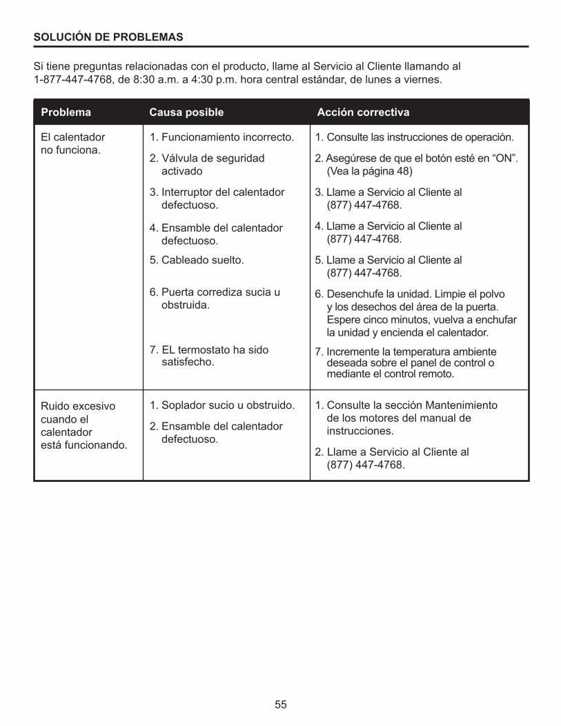
55
SOLUCIÓN DE PROBLEMAS
Si tiene preguntas relacionadas con el producto, llame al Servicio al Cliente llamando al 1-877-447-4768, de 8:30 a.m. a 4:30 p.m. hora central estándar, de lunes a viernes.
Problema Causa posible Acción correctiva
Ruido excesivo cuando el calentador está funcionando.
El calentador no funciona.
1. Soplador sucio u obstruido.
2. Ensamble del calentador defectuoso.
1. Funcionamiento incorrecto.
2.Válvuladeseguridadactivado
3. Interruptor del calentador defectuoso.
4. Ensamble del calentador defectuoso.
5. Cableado suelto.
6. Puertacorredizasuciauobstruida.
7. EL termostato ha sido satisfecho.
1. Consulte la sección Mantenimiento de los motores del manual de instrucciones.
2. Llame a Servicio al Cliente al (877) 447-4768.
1. Consulte las instrucciones de operación.
2.Asegúresedequeelbotónestéen“ON”.(Vealapágina48)
3. Llame a Servicio al Cliente al (877) 447-4768.
4. Llame a Servicio al Cliente al (877) 447-4768.
5. Llame a Servicio al Cliente al (877) 447-4768.
6. Desenchufe la unidad. Limpie el polvo y los desechos del área de la puerta. Espere cinco minutos, vuelva a enchufar la unidad y encienda el calentador.
7. Incremente la temperatura ambiente deseada sobre el panel de control o mediante el control remoto.

56
Elfabricantegarantizaquesunuevachimeneaeléctricanopresentarádefectosdefabricaciónnimaterialesduranteunperíododeunañoapartirdelafechadecompra,siempreycuandosecumplan las siguientes condiciones y limitaciones.1. Estachimeneaeléctricasedebeinstalaryoperarentodomomentodeacuerdoconlas
instrucciones de instalación y operación proporcionadas con el producto. Cualquier alteración, abusodeliberado,accidenteousoinadecuadodelproductoanularáestagarantía.
2. Estagarantíanoestransferibleysóloestádisponibleparaelpropietariooriginal,siempreycuandolacomprasehayarealizadoatravésdeunproveedorautorizadodelaCompañía.
3. Estagarantíaselimitaalareparaciónoreemplazodepiezasqueseconsiderendefectuosasenmaterialomanodeobra,siempreycuandodichapiezahayaestadosometidaacondicionesnormalesdeusoyservicio,despuésdequeunainspecciónporpartedelaCompañíaconfirmedicho defecto.
4. LaCompañíapodrá,bajosucriterio,eximirsedetodaobligaciónrespectodeestagarantíareembolsandoelprecioalpormayordelapiezadefectuosa.
5. Estagarantíanocubriráningúncostodeinstalación,manodeobra,construcción,transporteodeotrotipoquesurjadelapiezadefectuosa,sureparación,reemplazouotrasituación,ylaCompañíanoasumiráningunaresponsabilidadporlasmismas.LaCompañíatampocoseráresponsable por ningún daño accidental, indirecto o resultante, salvo que la ley estipule lo contrario.
6. Medianteelpresente,seexcluyeexpresamentecualquierotragarantía,expresaoimplícita,respecto del producto, sus componentes y accesorios, o cualquier otra obligación o responsabilidaddepartedelaCompañía.
7. LaCompañíanoasume,niautorizaaningúnterceroaasumirensunombre,ningunaotraresponsabilidad respecto de la venta de este producto.
8. Lasgarantíasdescritasenestedocumentonoseaplicanaaccesoriosquenoseandeelfabricante y que se usen junto con la instalación de este producto.
Esta garantía es nula si:a) Lachimeneahafuncionadoenatmósferascontaminadasconcloro,flúoruotrassustancias
químicasdañinas.b) Lachimeneaestásometidaaperíodosprolongadosdehumedadocondensación.c) Se produce cualquier alteración, abuso deliberado, accidente o uso inadecuado del producto.
SI SE NECESITA SERVICIO DE GARANTÍA. . .1) Póngase en contacto con el Servicio al Cliente de el fabricante. Asegúresedetenersugarantía,surecibodeventayel modelo o número de serie de su producto el fabricante.2) NOINTENTEREALIZARNINGÚNTRABAJO DE REPARACIÓN USTED MISMO.
GARANTÍA
GHP Group, Inc.6440 W. Howard St.Niles, IL 60714-3302877-447-4768

57
LISTA DE PIEZAS DE REPUESTO
Parapedirpiezasderepuesto,llameanuestrodepartamentodeServicioalClienteal 1-877-447-4768, de 8:30 a.m. a 4:30 p.m. hora central estándar, de lunes a viernes.
Ref. Descripción23-800-001GLF-2308
GEF23TRG18
28-800-001GLF-2808
GEF28TRG18
1 EF23350AC EF28350AC
2 EF23106AC EF23106AC
3 EF23107AC EF28107AC
4 EF23354AC-13 EF28354AC
5 EF23108AC EF28108AC
6 EF23356AC EF28356AC
7 EF33405A-12 EF33405A-12
8 EF33501A EF33501A
9 EF23372AC EF28374AC
10 EF23373AS-12 EF28377A-12
11 EF28368AC EF28368AC
12 EF28369AS EF28369AS
13 EF23371AS EF28373
14 EF23511A-12
15 EF33504AC-12
16 EF33510AS-12 EF33510AS-12
17 EF33515A EF33515A
18 EF33508A EF33508A
19 EF28375AC
20 EF28381AC
21 EF33109A
22 EF23511A-12
23 EF33504AC-12
24 EF24900014AC
Tablero de circuitos del panel de control
Tablero de circuitos del panel de control
Interruptor de palanca
Panel lateral izquierdo de ladrillo
Panel lateral derecho de ladrillo
Ensamble de luz hacia abajo
Juego de leños
Gráfico del panel de control
Tablero de circuitos del panel de control
Control remoto
Cable de alimentación y conector
Motor-B
Kit del soporte de instalación
Calentador
Malla
Reflector de llamas
Cama de brasas-Tira de luces LED
Llama-Luces LED-Tira
Panel superior
Ensamble de panel lateral izquierdo
Ensamble de panel lateral derecho
Panel posterior
Ensamble de reborde
Panel de llamas

58
Impreso en China
14 15
1
6
11 12 13
1617 18 19 20
21
7 8 9
10
2 3 4 5
2322
24