Ho So Thau May Phat Analog Co the Nang Cap Len T2 Cua DD India T1 2013
69
PRASAR BHARATI (Broadcasting Corporation of India) ~~G~l~ ~Qlr':'-'~~ll~<-f Directorate General Doordarshan <a.'<.",~'i--1 ~, Chi '-f'<.r~ct-*"l ~, Doordarshan Bhawan, Copernicus Marg ~ IG~I- ~~ooo~ New Delhi - 110001 Specification No: DG:DD/TxD/HPT/EV-2012 Dated 17.12.2012 SPECIFICATIONS FOR SUPPLY, TESTING AND COMMISSIONING OF THREE NOS. OF 10KW (1+1) DVB-T2 UPGRADABLE UHF ANALOG TV TRANSMITTERS ALONGWITH STATION ITEMS TO BE INSTALLED IN JAMMU REGION, SRINAGAR REGION & LEH REGION
Transcript of Ho So Thau May Phat Analog Co the Nang Cap Len T2 Cua DD India T1 2013

PRASAR BHARATI(Broadcasting Corporation of India)
~~G~l~ ~Qlr':'-'~~ll~<-f
Directorate General Doordarshan<a.'<.",~'i--1 ~, Chi '-f'<.r~ct-*"l ~,
Doordarshan Bhawan, Copernicus Marg~ IG~I- ~~ooo~
New Delhi - 110001
Specification No: DG:DD/TxD/HPT/EV-2012Dated 17.12.2012
SPECIFICATIONS FOR SUPPLY, TESTING AND COMMISSIONING OFTHREE NOS. OF 10KW (1+1) DVB-T2 UPGRADABLE UHF ANALOG TV
TRANSMITTERS ALONGWITH STATION ITEMS TO BE INSTALLED INJAMMU REGION, SRINAGAR REGION & LEH REGION

SPECIFICATIONS FOR SUPPLY, TESTING AND COMMISSIONING OF THREENOS. OF 10KW (1+1) DVB-T2 UPGRADABLE UHF ANALOG TV TRANSMITTERS
ALONGWITH STATION ITEMS TO BE INSTALLED IN JAMMU REGION,SRINAGAR REGION & LEH REGION
TABLE OF CONTENTS
1. INTRODUCTION 4
2. THE SCOPE OF THE TENDER 4
3. ESSENTIAL ELIGIBILITY CRITERIA FOR BIDDER 5
4. GENERAL REQUIREMENTS FOR COMPLETING THE OFFER 6
5. DELIVERY 10
6. GUARANTEE 10
7. MAINTENANCE SUPPORT/SPARES 11
8. LOCAL REPRESENTATIVEIDEALER 12
9. TRAINING AT OEM'S WORKS 12
10. TRAINING AT SITE 13
11. INSPECTION 13
12. TESTING AND COMMISSIONING AT SITE 14
13. BOM (UNPRICED) 14
14. LOCAL / REMOTE MONITORING AND CONTROL FACILITY 15
15. SOFTWARE 16
16. INPUT, MONITORING AND MEASURING EQUIPMENT RACK 17
17. TRANSMITTER SYSTEM ' 17
18. EXCITER 18
19. POWER AMPLIFIER SySTEM 18
20. LIQUID COOLING SySTEM 19
21. UPGRADEABILITY TO DVB-T2 TRANSMITTER. 20
22. TECHNICAL SPECIFICATIONS FOR ONE 10 KW ANALOG TVTRANSMITTER SYSTEM 24
23. COMPLIANCE STATEMENT 27
ANNEXURE-I 29
B~LLOF MATERIAL FOR (1+1), 10KW UHF BAND IV/V ANALOG TVTRANSMITTER SYSTEM & STATION ITEMS FOR THREE LOCATIONS IN J &K 29
DG :DD/TxD/10kW /2012/EV / Page 1 of 68

ANNEXURE II-1 35
SPECIFICATIONS OF 10KW BROADCAST POWER MONITOR 35
ANNEXURE 11-2 36
A. SPECIFICATIONS OF INDOOR COAXIAL FEEDER CU COMPONENTS 36
B. SPECIFICATIONS FOR 15 KW MOTORISED R.F. COAXIAL SWITCH 36
ANNEXURE 11-3 37
A. SPECIFICATIONS OF STANDARD 19" RACK 37
B. SPECIFICATIONS OF VIDEO EQUALIZING DISTRIBUTION AMPLIFIER ..38
C. SPECIFICATIONS OF AUDIO VIDEO SWITCHER 38
D. SPECIFICATIONS OF AUDIO JACK PANEL-(N/C) 2X24 40
E. SPECIFICATION OF VIDEO JACK PANELS 40
F. AUDIO PATCH CORDS (2FT) 40
G. VIDEO PATCH CORDS (2 FT) 40
H. SPECIFICATIONS OF AUDIO STEREO MONITORING AMPLIFIER 8 W 40
I. SPECIFICATIONS OF AUDIO DISTRIBUTION AMPLIFIER. 42
J. SPECIFICATIONS FOR AUDIO PROCESSOR 42
K. SPECIFICATION OF AMPLISPEAKER 44
L. BROAD SPECIFICATION OF LOUDSPEAKER 45
M. SPECIFICATIONS OF VU METER 45
ANNEXURE 11-4 47
SPECIFICATIONS OF WAVEFORM MONITOR 47
ANNEXURE 11-5 50
SPECIFICA TIONS OF COMPUTER WITH 800 VA UPS AND LASERJET PRINTER................................................................................................................................................. 50
ANNEXURE 11-6 52
SPECIFICATIONS OF 10 KW DUMMY LOAD 52
ANNEXURE 11-7 53
A. SPECIFICATIONS OF COLOUR TEST PATTERN & TONE GENERATOR 53
B. SPECIFICATIONS OF RF ANALYSER 53
C. SPECIFICA TIONS OF AUDIO ANALYSER 57
ANNEXURE 11-8 59
A. SPECIFICATIONS OF RF STEP ATTENUATOR (0 -100 DB) 59
DG:DD/TxD/10kW/2012/EV/ V W Page20lGB

B. SPECIFICATIONS OF RF FIXED ATTENUATOR 3 DB, 6 DB, 12 DB (N TYPE) 59
ANNEXURE II -9 60
C BAND/KU BAND SATELLITE RECEIVE EQUIPMENT 60
A. SPECIFICATIONS OF PROFESSIONAL IRD FOR C-BAND/KU-BAND: 60
B. SPECIFICATIONS OF CABLES, CONNECTERS 63
C. SPECIFICATIONS FOR THE LNBC IN C BAND 64
D. SPECIFICATIONS FOR KU BAND FEED, CABLE, DISH, AND LNBC 64
ANNEXURE 11-10 67
SPECIFICATION FOR RF POWER METER WITH SENSORS 67
ANNEXURE III 68
INDICATIVE SKETCH FOR 10KW (1+1) TRANSMITTER SYSTEM AT ONELOC ATI0N 68
DG :DD/TxD/10kW /2012/EV / Page 3 of 68

SPECIFICATIONS FOR SUPPLY, TESTING AND COMMISSIONING (STC)OF THREE NOS. OF 10KW (1+1) DVB-T2 UPGRADABLE UHF ANALOG TVTRANSMITTERS ALONGWITH STATION ITEMS TO BE INSTALLED IN
JAMMU REGION, SRINAGAR REGION & LEH REGION.
1. Introduction
a) Doordarshan (DD) intends to installlOkW (1+1) Analog UHF TV Transmitterswhich are DVB-T2 upgradable, at three locations in J & K. The locations are inJammu Region, Srinagar Region and Leh Region.
b)These transmitters shall be based on the latest technology and shall haveprovision for remote monitoring, remote operation and remote Control.
c) The TV transmitters are to be supplied as a complete system including input,monitoring and measuring equipment, liquid cooling system, UPS, isolationtransformer, AVR, interconnecting cables etc.
d) 'Transmitter System' includes Transmitter alongwith its associated equipmentsuch as liquid cooling system, dummy load, RF rigid lines, RF coaxial switch,Input, monitoring and measuring Equipment, UPS, isolation transformer, AVR,interconnecting cables etc.
e)A list of items/equipment which is treated essential for completeness of thesystem is provided with these specifications in Annexure-I. Any otheritem/equipment, which is essential for the completeness of the system, shouldalso be included in the offer. It is the responsibility of the bidder to ensurethat the system is complete in all respects.
£) Channel frequencies for the three transmitters are given below:
Table 1
S. Station Frequency band Operating ChannelNo Freauencvl. Green Ridge UHFbandIVN Ch#22 (478MHz to
( Srinagar Region) (470MHz to 862 486 MHz)MHz)
2. Natha Top UHF band IVN Ch#31 (550MHz to(Jammu Region) (470MHz to 862 558 MHz)
MHz)3. Himbotingla UHFbandIVN Ch#25 (502MHz to
( Leh Region) (470MHz to 862 510 MHz)MHz)
2. The scope of the tender
The scope of the present tender is to supply the required set of equipment,acceptance testing & commissioning at sites, training etc. as specified in thesespecifications. The installation of all the equipment of the Transmitter System at
DG'DD!hD!10kW!2012!EV!~;f ~ Page4 of 68

site will be done by Doordarshan. The main equipment includes the following forwhich Bill of Material (BOM) is given in Annexure I:
a. 10kW (1+1) Analog UHF TV Transmitters which are DVB-T2upgradable.
b. Input and monitoring equipment with pre-wired racks.
3. Essential eligibility criteria for bidder
a) The bidder should be the original equipment manufacturer (OEM) of TVTransmitter or t4eir authorized representative/dealer.
b) The OEM of the transmitter must have an experience of manufacturing andsupplying UHF Analog TV transmitters of not less than lOkW power outputfor at least last 10 years as on 31.12.2012. Documentary evidence to supportthis must be provided. The OEM must provide the detail of past supply recordin the format given below in Para 3(c) for last ten years for at least 40 no. ofsuch Transmitters, alongwith copies of orders for supply of at least 10 nos. ofsuch TV transmitters.
c) The Transmitter OEM should have at least three years' experience ofupgrading the Analog Transmitter, on 31.12.2012, for DVB-T2 operation bysuitably adding DVB-T2 modulator, software etc, to deliver at least 5kW DVB-T2 Power. Documentary evidence must be submitted with the offer
ORThe OEMs must have at least three years' experience of manufacturing andsupplying of DVB-T2 transmitters, on 31.12.2012, of at least 5kW DVB-T2power, to broadcasters or broadcast network operators. Details of past supplyrecord of such DVB-T2 transmitters to various organizations must be providedin the format given in below to support this:
Order Transmitter Quantity Name of the Details * of performanceNo. with Type, Model broadcaster with certificates of the contract.date, and Power full postalreference of address to whom
transmitter transmitter wassupplied.
(1) (2) (3) (4) (5)
*Copies of actual performance certificates are to be enclosed by the bidder.
d) In case the bidder is the authorized representative/dealer of the transmitterOEM, it must be in the business of sales and supply of T.V. or radio transmittersystems of power not less than 10k W for at least last two years as on31.12.2012. Documentary evidence to support this must be provided.
e) The bidder must have his local office/authorized representative/dealer in
DG :DD/TxD/10kW /2012/EV / Page 5 of 68

Page 6 of 68
India for after sales service and support. The local office/authorizedrepresentative/dealer will be the nodal point for resolving issues related totesting and commissioning at site and after sales service and support. Anymodule of transmitter or other equipment requiring repairs will be handed overto local office/authorized representative/dealer that will arrange repairslocally or export the defective modules to OEM's factory and re-import afterrepairs. However, during Guarantee Period, it would be responsibility of localoffice/authorized representative/dealer to collect the module of transmitter orother equipment requiring repairs from the site themselves. It is theresponsibility of local office/authorized representative/dealer to arrange therepair/replacement of faulty items. The cost of transportation, repairs etc.shall be borne by the bidder during the Guarantee period.
f)The OEM of the offered TV Transmitter must have his own local office or itsrepresentatives/dealers in India for after sale service and support. Aftersales service support for the repairs/maintenance of transmitter system after thecompletion of guarantee period, shall also be provided by the respective OEMsof the transmitter and other allied equipment either directly or through theirrepresentatives/dealers in India. A certificate as per Annexure III, on theirletterhead, in this regard duly signed by the respective OEMs must besubmitted with the offer.
4. General Requirements for completing the offera) The bidder will attach all relevant technical documents in English like
'offered bill of materials with quantity, unit, make and model', Technicalpamphlets, manuals, data sheets, drawings, block diagrams, photographsetc. of all equipment offered with the transmitter system that are essentialto evaluate the offer for technical suitability with reference to DDspecifications. A copy of the Installation manual, Operation andmaintenance manual must be enclosed with technical bid for assessing theTransmitter system. The transmitter shall be installed by Doordarshan asper the instructions given in the installation manual. The installation manualand the operation & maintenance manual must include at least the detailsgiven in sub-paras (b) and (c) below:
b) The installation manual must describe the following information:i. A suggestive floor equipment layout plan drawing with
dimensions in meters for installation of the TV transmittersystem in a transmitter hall with all allied equipment.
11. Diagram showing the isometric view of TV Transmitter andallied equipment with dimensions· in meters are to beprovided.
111. All installation drawings with dimensions in respect of allsupplied equipment are to be provided.
IV. All mechanical assembly drawings of the TV transmitters~m Wit~dimensions are to be provided.
DG'DD/T'D/1DkW/2D12/EV/ ~~ ~,,---'

v. All the views, i.e. front, rear, top and side (open) of the TVTransmitters with dimensions are to be provided.
VI. Detailed descriptions for installation of cooling systemalongwith the diagrams showing the coolant flow to thetransmitter and the outlet to heat exchanger system should beprovided.
V11. Typical installation drawings with dimensions of heatexchanger are to be provided.
Vlll. The details of unpacking are to be provided.IX. A detailed write up in English regarding installation of TV
Transmitter system along with its associated equipment itemsshould be provided.
x. The procedure of alignment and adjustment of variousassemblies & sub-assemblies of TV Transmitter such asExciter, PA, Control Circuit, output stage etc. should bedescribed in detail with practical example in the installationmanual.
Xl. All Do's and Don'ts which are essential for safeinstallation of the Transmitter System should be describedin the installation manual.
X11. An inter-wiring diagram for all equipment installed in theinput & monitoring rack must also be provided in this manual.
c) Operation and Maintenance Manual must describe in it the followinginformation:
1. General description of transmitter, transmitter block diagram/Schematic drawings indicating the details of different blocks,modules and redundancy incorporated in transmitter and itssubsystems.
11. General description and structural overview of the Transmitterracks and Pump Racks indicating the position of differentmodules, units, power distribution etc. front and rear, top, side(open) views of the transmitters rack with dimensions.
111. Colour Photographs of Transmitter showing the following:1. Front view of the transmitter2. Rear view of the transmitter3. View of PA with cover opened showing full view of
palletslRF Boards and various adjusting pots.4. Enlarged Open view of PA showing at least two RF
transistors and bias adjustment pots.5. Front view and rear view ofPA.6. Open view of SMPS.7. Open view of Exciter.8. Screen shots of various display screens showing
monitorable and measurable Parameters of transmitter.
DG:DD/TxD/lOkW /2012/EV / Page 7 of 68

Page 8 of 68
IV. A detailed description with all relevant circuit diagrams of thetransmitter should be provided with details oftest points.
v. The details of all electrical circuits in various stages of theTransmitter used along with their write-ups are to be providedin this manual.
VI. General description of RF signal flow diagram for completeRF chain from exciter to filter output with information aboutpower level and frequency at input & output of each stage.Losses and gains in various stages including power dividers,combiners, etc. must also be shown.
Vll. Description of Transmitter interlocks, protections underabnormal conditions and schematic drawing indicatinginterconnections to different transmitter units, external unitsand accessories like dummy load, changeover switches, rejectloads, cooling pumps etc. which are wired in Transmitterinterlocks.
Vlll. Details and Schematic drawings of liquid cooling system withdescription.
IX. Details and schematic drawings of remote control & operationby telemetry system using Ethernet/ SNMP/web browser andbroadband connection along with screen shots of the interfacedisplays. The remotely monitorable and controllableparameters of the transmitter should be clearly indicated.
x. General description of Transmitter Control System andschematic drawing for control signal distribution.
Xl. A detailed description with all relevant circuit diagrams forthe control circuit of the transmitter should be provided.
Xll. General description of exciter system, block schematicshowing details of all sub units. Exciter Front and rear viewsindicating all inputs, outputs and interfaces.
Xlll. Description of upgrading the transmitter system to DVB-T2with required changes in Exciter and filter.
XIV. The description of frequency stability with the help of circuitdiagram.
xv. General description and architecture of Power Amplifier'sblock schematic drawings, Front, open and rear VIewsindicating all inputs, outputs and interfaces.
XVI. Full detailed description with the help of circuit diagrams andcircuit analysis of Exciter system, PA, SMPS of PA.
XVll. Description of measurement of various DC voltages, currentsand RF power of power amplifier.
XVlll. Description of reserve power capacity and output powerregulation mechanism and protection mechanism against highVSWR, high RF output, high temperature, of the PowerAmplifiers and Transmitter.
DG'DD/TxD/1DkW/2D12/EV/ ~ ~

XIX. Description of VSWR foldback alongwith range of foldback.The explanation of foldback with the help of circuit diagrammust also be provided.
xx. Description of Protection of SMPS of Power Amplifieragainst over current, over voltage and over temperature withthe help of circuit diagram.
XXI. Details of Splitter and Combiner system's schematic drawingsused in the transmitter.
XXll. The operating manual should have description regardingvarious interfaces, connectors, connecting cables andaccessories required for the satisfactory function of the TVTransmitter.
XX111. A complete list of all parts/transistors/ICs VLSI/ Componentsused in the transmitter must be provided in this manual.
XXIV. The names and number (type) of LDMOS/MOS devicesbased on latest Technology used in the power amplifier mustbe clearly mentioned.
xxv. Technical data sheet of all high power RF devices/RFcomponents used in the transmitter.
XXVI. All details of putting "ON" the transmitter, with the sequenceof operation of the Transmitter for switching ON.
XXVll. Procedure for changing the frequency of operation of thetransmitters.
XXV111. Procedure for operating the transmitter on low power upto 6dB below rated power.
XXIX. The detailed procedure and possibilities of By-passing controlcircuit with diagrams.
xxx. The description of manual operation of control system andcooling system.
XXXI. General description of electrical power distribution andschematic drawing of power supply system used for thetransmitter system.
XXXll. All Do's and Don'ts which are essential for safe Operation& Maintenance of the Transmitter should be described inthe Operation & Maintenance manual.
XXXllI. The various test and measuring equipment required andessential for the routine maintenance and calibration alongwith the procedure for taking such measurement should beprovided in the manual.
XXXIV. Various test fixtures and accessories required for themaintenance/ repair of the TV Transmitter should be clearlydescribed in this manual.
xxxv. The detailed procedure for trouble shooting of the TVTransmitter preferably up to component level should bedescribed in the manual.
DG:DD/TxD/10kW j2012jEV j Page 9 of 68
XXXVI. The systematic trouble shooting/fault tree and flow diagramshould be provided for diagnosis of the faults with theirremedial measures in this manual.
XXXVll. The routine maintenance schedule for the transmitter shouldalso be described in the manual.
XXXVlll. Soft copies of the above manuals must also be submittedalongwith the offer.
XXXIX. The Transmitter OEM must ensure that all the detailsrequired in (i) to (xxxvii) mentioned above are included inthe literature provided with the technical bid both in hardas well as soft copy.
5. DeliveryThe complete set of the 'transmitter system' with all allied equipment as perBOM given in Annexure I is to be delivered in good condition at each of thethree sites mentioned in Table 1. It will be the responsibility of the bidder toensure safe delivery of all the equipment at each of these three sites.
6. Guaranteea) The respective manufacturers shall guarantee the satisfactory working of
all the equipment of the Transmitter System, for twenty four monthsfrom the date of completion of acceptance test at site or for thirty monthsfrom the date of receipt of last accepted consignment at site whichever isearlier. Any defect/ failure of any component, module, assembly of anyequipment and its non-performance during this period is to be set rightby the bidder/ manufacturer(s) free of cost and the repaired/replaceditem(s) to be delivered at the premises of the consignee.
b) A Guarantee certificate, as in Para 6(a), from the respective OEMs ontheir letter heads, for the third party bought equipment/items offeredwith the transmitter system, must also be attached with the offer.
c) Any Future upgrade of software or Software updates for all theequipment (such as Transmitter, all input, monitoring, measuring andallied equipment etc.) within twenty four months of commissioning ofthe Transmitter System or for thirty months from the date of receipt oflast accepted consignment at site whichever is earlier shall be availablefree of cost to Doordarshan. Backward compatibility of the softwaremust also be ensured for that equipment/item.
d) Any module/Assembly/ Sub Assembly of the transmitter system or thepower supply system failing during the guarantee period shall berepaired/replaced free of charge by the bidder at site. The transportationcharges if any shall be borne by the bidder. Guarantee period of thatmodule/Assembly/ Sub Assembly would be extended corresponding to
DG,DD!TxD!10kW!2012!EV! ~ ~ Page 10 of 68
-..•••..

the outage period, if the repair/replacement of the failed item takes morethan 30 days.
1. DD will intimate the fault to the OEM or its authorisedrepresentative/dealer or local office/authorized representative/dealer of the bidder, who will deploy the staff at site within 3days and attend the fault within a week.
11. In case it is not possible to repair the defective unit/module atsite, the above mentioned nodal office will provide thereplacement unit/module to ensure the continuity of the service.
111. In case the unit is to be sent to the OEM for repairs, it has to berepaired and fitted back within 30 days of intimation of fault.
7. Maintenance support/spares
a) The minimum recommended essential spares (like modules of PA, PowerSupply Modules or any other critical spares suggested by the OEM),required to maintain the continued service of transmitter in a reliablemanner, shall be quoted separately by the supplier positively.
b) The minimum, recommended essential spares may be based on predictedrate of failure and requirement for three years.
c) The manufacturer shall also give a certificate attached with the offer tosupply maintenance support and all spares during the lifetime of the TVTransmitter. The life of the TV transmitter must be certified by themanufacturer. The life of transmitter should be more than Ten years.
d) The bidder must also attach with the offer the certificates to supply allspares, installed softwares and software updates for providing maintenancesupport during the lifetime of all the input, monitoring and all otherauxiliary items/equipment offered with the transmitter system.
e) The lifetime of all other major items such as measuring Equipment, UPS,AVR etc. must also be provided by the respective OEMs.
1) The maintenance support of each equipment/items/ allied equipmentsupplied is to be ensured by the respective OEMs. Duly signed necessarycertificates in this regard are to be provided by the respective OEMs onlyon their letter heads.
g) In case the bidder quotes the optional items as 'a set', the details of thecomponents/items offered in the 'set' must be spelt out clearly includingtheir Model Nos. and quantity, failing which the tender is likely to berejected.
h) The spares shall be treated as optional items and the cost of spares shall notbe taken into account while deciding the lowest bidder.
i) In addition, the bidder shall provide, in the following format, the addressand contact information for after sales service and support of all the
DG :DD/TxD/IOkW /2012/EV /Page 11 of 68

equipment including the third party bought out equipment or at leastfor IRDs, 4.8 M PDA, Audio-Video Switcher, Audio Analyser, Test Patterngenerator, WPM, VDA, ADA, RF Analyser, Broadcast Power Monitor,Dummy Load, RF Co-axial switch, UPS, Battery Bank, IsolationTransformer, AVR that are to be supplied with the transmitter system aspart of input, monitoring, measuring or allied equipment.
Name of OEM After sales & Name, Authorization byEquipment support office Telephone/ Fax! the OEM forwith model address Email of supply and afterNo. concerned sales service and
personnel support of theequipment
(1) (2) (3) (4) (5)
8. LocalRepresentative/Dealera) Documentary evidence about local after sales and support arrangement
as per Para 3(e & f) above for the transmitter system must be providedwith the offer. The address, contact details of local office/representative,details of technical staff, their qualification and experience etc. must beprovided with the offer.
b) In case any item of transmitter system requires repairs at works/factory,the same would be handed over to local office /Representative/Dealer ofOEM/bidder in India, who would arrange export of the item toworks/factory and re-import in India after repairs.
c) After sales service and maintenance support of the transmitter should beavailable in India through the local office/Representative/Dealer evenafter the guarantee period is over and throughout the life of thetransmitter as certified by the OEM.
d) Copy of Agreement! MoU signed in this regard between OEMs and theirlocal representative/dealer must be submitted with the offer.
9. Training at OEM'sWorksa) A proposal should be attached with the offer for training on operation &
maintenance, installation and testing of the offered TV transmitter to fiveDoordarshan Engineers at Transmitter Manufacturer's works for 5 days.
b) The training programme will be structured so as to cover theory ofoperation Maintenance, Practical demonstrations of circuits, Maintenancedemonstrations, Fault finding, Circuit Tracing exercises, Part Replacements,installation and testing of the offered TV Transmitters.
c) Two sets of training lecturers notes, schematic drawing, hand book etc. shall besupplied to DDG(E) (Transmitter Design), DG: DD also.
d) The offer shall include training fee only (To & Fro air fare, per diem, lodging,boarding charges etc. for DD Engineers shall be borne be Doordarshan and are
OG,OO/TxO/10kW/2012/EV/ V ~ Page 12 of 68'-

not to be quoted.) The cost of training shall be included in the essential itemsofBOM.
10.Training at Sitea) OEM(s)' representative(s) shall offer one day trammg on operation and
configuration of Transmitter System at site after site acceptance test.b) Two sets of training lecturers notes, schematic drawing, hand book etc. shall be
supplied to DDG(E) (Transmitter Design), DG: DD also.e) Training fee quoted by the bidder shall include all charges like training fee,
travel, boarding, lodging and local transport charges for deputing the OEMexpert(s). DD shall bear all touring expenses of DD engineers deputed fortraining and the same is not to be included by the bidder in their offer. Thetraining fee if any shall be included in the essential items of BOM for decidinglowest offer.
d) The training shall cover theoretical concepts, demonstration of features,Software, Configuration of Transmitter units, operational & maintenanceinstructions, fault finding, circuit tracing, component/ module replacements,trouble shooting, preventive maintenance and other relevant topics etc. relatedto the 0 & M of the transmitter.
e) Training material in hard and soft copies is to be provided to each DDengineer undergoing the above training.
11.Inspectiona) ATP: A copy of ATP (Acceptance Test Procedure) must be submitted by the
bidder with the offer. ATP should describe the standard testing proceduresand the details of test benches for carrying out measurement etc. for theoffered transmitter. The test reports will not be treated as ATP. The OEMonly shall prepare the ATP for their product being offered. The ATP shall beapproved by Doordarshan after necessary modifications if required. Theapproved ATP shall be sent back only to the successful bidder and is to beused for inspection of transmitter by two DD Engineers at OEM's worksbefore dispatch of the Transmitter.
b) The bidder has to intimate DD for inspection and testing of the Transmitter, atleast eight weeks in advance when the equipment are likely to be ready forinspection. Inspection period will be three days for each transmitter.
c) The bidder shall quote inspection fees only in his offer excluding theexpenditure for DD inspectors on To & fro airfare, per Diem allowances,lodging, boarding charges etc. which shall be borne by Doordarshan. Theinspection fee if any shall be included in the essential items of BOM.
d) In case, inspection at OEM's works is not carried out, the transmitter shall beaccepted on the basis of Factory test report, duly signed and stamped on theletterhead of the OEM, provided by the OEM of the transmitter which shouldreach the site alongwith the transmitter.
e) All other associated equipment, items and accessories will be accepted on thebasis of OEM's Test Certificates (as per DD Specification) duly signed and
DG:DD/TxD/lOkW /2012/EV /Page 13 of 68

stamped on the letter head of the OEM, failing which Test Certificates will beconsidered incomplete and equipment offered by the firm is liable to berejected. All the test certificates should reach the site alongwith the respectiveequipment.
12.Testing and Commissioning at site: Site Acceptance Test (SAT)a)The transmitter system shall be installed by Doordarshan as per the instructions
contained in the manufacturer's installation manual. DD will intimate thebidder when··the installation of the transmitter system is completed, givingthem three weeks' time for completing travel formalities etc. Therepresentative of Transmitter OEM shall visit the site for site acceptance testand commissioning. The testing and commissioning shall be completed within7 days.
b) For this purpose complete SAT Procedure will be prepared by theOEMlbidder in respect of transmitter system and the power supply system andshall be submitted for the approval by DD. The endurance test of eachtransmitter shall also be part of SAT. The test procedure shall indicate fulldetails of test set up and equipment required during the Acceptance Testing atthe site. All the test equipment needed for site acceptance are to be arranged bythe bidder.
c)The OEM's representative will examine transmitter installation for correctness.Thereafter, the 'First Power ON' at site of the entire system shall be done bythe OEM's representative (s). However, if necessary, the OEM may includeappropriate measure in the equipment to avoid any 'Power ON' before SAT.
d) The expenditure for OEM engineer(s), representative(s) on travel,lodging, boarding, daily allowances etc. for site acceptance testing shall beborne by the bidder.
e)The maximum duration of installation of transmitter system at site shall be 9months from the date of receipt of all the material in good condition at site.
13.80M (Unpriced)a) A detailed, complete Bill of material (BOM), exactly in the same format as in
the price bid, shall be attached with the technical, bid leaving price columnblank.
b) Make, model, quantity and unit of each item must be mentioned clearly in theBOM. In case of 'set' complete details of all components that form partof set should be spelt out clearly i.e. the details of the component/itemoffered in the set including their part no. and quantities must be mentionedclearly.
c) The BOM is provided in Annexure I for 10 kW UHF Transmitters with stationitems for both the transmitters.
d) The bidder must quote for all the items of Annexure I. The offer withincomplete BOM shall be rejected.
e) It is the responsibility of the bidder to ensure the completeness of the offeredsystem. In case, the bidder fails to offer any item(s) which is found essentialduring installation, the same shall have to be supplied free of cost.
DG,DD/TxD/lOkW/2Dl2/EV/ V ~ Pagel'olG8

f) The bidder must quote all the items listed III 'Essential items' as well as'Optional items' of the BOM.
14. Local/remote Monitoring and control Facilitya) Each transmitter should have all provisions of local LCD display, keypad, panels
etc. for local operation, monitoring/control.b)All parameters and working status of modules specified in Para(j) (i to xxi)
given below should be available for local monitoring.c) Detailed information on the parameters and features available for local
monitoring and Control of the transmitter is to be submitted with the offer.d) The transmitter shall have Control/operation and monitoring of the parameters
locally as well as at remote-location through web interface.e)The Control/operation and monitoring Software would run on normal PC with
Windows platform.f) The transmitter should have a 'WEB' GUI interface using TCP/IP. Necessary
Transmitter functions Control & monitoring shall be provided via the remote"WEB" GUI interface.
g) Full functional description alongwith diagrams, block schematics, flow charts,pictures of various screens etc. must be attached with the offer.
h)Both the transmitters should be remotely as well as locally monitorable/operableindividually.
i) Alarms and logging provision should also be available for logging events andfaults for minimum 1000 logs.
j) Remotely and Locally Monitorable parameters: Following parameters oftransmitter are to be made available for monitoring on the PC at the remotelocation as well as on local PC. Details about all the individual screens may beprovided with the offer.
1. Forward vision RF power11. Reflected vision RF power
111. Forward aural RF powerIV. Reflected aural RF powerv. Output Power of each PA
VI. Reflected power of each PAV11. DC power supply voltages of each PA
Vlll. PA transistor/pallet currents for driversIX. PA transistor/pallet currents for intermediate stagex. PA transistor/pallet currents for final stage.
Xl. PA heat sink temperatureX11. Status of exciter in circuit
Xlll. Exciter output powerXIV. AGC levelxv. Coolant Temperature
XVI. Status of pumps in circuit
DG:DD/TxD/lOkW /2012/EV /Page 15 of 68
XVll. Status of heat exchangerXV1l1. Summary fault log
XIX. Fault and interlock indication: exciter fault, High reflectionlVSWR andindications.
xx. Alarms for PA's VSWR, Temperature, Exciter fault alarm.XXI. Any other parameter which the Transmitter manufacturer thinks
essential for proper functioning of a remote Controlled/operatedtransmitter.
k)Automatic Control unit (ACU):i. The description of complete switching sequence of transmitters and
associated equipment along with all monitoring and Control features of thetransmitter must be provided.
11. One automatic changeover unit (ACU) for operating the Transmitters in(1+ 1) mode to facilitate automatic switch "ON" of the second Transmitterunit in case of failure of RF output of the first Transmitter unit, shall besupplied with each set.
111. When power of operating transmitter goes down by 3 dB, it should besensed as a 'failure' to switch to second transmitter automatically and itshould be connected to antenna load. The failed transmitter shall beconnected to dummy load.
IV. There should be provision for display for monitoring of (1+ 1) Transmitterin ACU.
v. There should be provision for switching ON & OFF and change-over oftransmitters remotely through ACU.
VI. Provision is to be made in the ACU to enable operating personnel tooperate the transmitter locally.
Vll. Arrangement shall be made for bypassing the ACU in case of its failure soas to enable operating personnel to operate the individual transmitter inmanual mode also.
V1l1. The ACU shall be provided and integrated by the OEM of the Transmitteronly.
1) Compatible P.c.s for local and remote monitoring, laser printers of reputed makeand UPS are also part of the tender. Specifications are given in Annexure II-5
15.Softwarea) One set of Copies of all softwares used in the transmitter system should
be provided in the form of CD besides being loaded in to the system.
DG,DD!TxD/1DkW/2D12/EV/ ~7 ~ Page 16 of 68

b) All software licenses are to be provided to Doordarshan on perpetuallicense basis without specifYing any time limit or without specifYing any'end of life' of any of the softwares supplied.
16.Input, Monitoring and Measuring Equipment RackThe equipment like IRD, lOx2 Audio-Video switcher, Waveform monitor,Colour Pattern Generator, and monitoring amplifier etc. should be installedin standard 19" wired rack(s). The TV Receivers need not be installed inRacks but be provided with suitable stands.
17.Transmitter SystemThe General features of transmitter system are as below:a) The transmitters should be rugged, reliable, and stable in operation under Indian
tropical conditions. The climate may vary from very cold to hot, humid anddusty. Specifications of the transmitters are given in this document. Allequipment would be used for 24x7 continuous operations.
b)Transmitter output should be 3W' EIA unflange copper. In case of Aluminium,suitable transfer coupler/rings to connect the output with the Copper rigid lineshould be supplied to avoid thermocouple effect.
c) The output of either of the two 10kW transmitters will be fed through single 4"Dia. R.F. Feeder Cable via R.F. Change Over Switch (C/O SW) to the single10kW UHF, Superturnstile Antenna system and the other transmitter to thedummy load.
d)There should be provision of interlock between Transmitter and Antennaload/Dummy Load so that transmitter is switched ON only when either of thetwo loads is connected.
e) The transmitter shall have its own VSWR fold back, automatically turning offthe PAs if the VSWR is still beyond a preset threshold after the three strikemode. The VSWR fold back range must be specified by the OEM in numericalvalues or graphically.
f) The offered transmitters should have low. level diplexing (CommonAmplification).
g)There should be provision for setting the lower and upper limits for the Forwardand Reflected Power.
h)A detailed block schematic diagram for the TV transmitter system with all itsconstituent items should be provided with the offer.
i) The power consumption of the UHF Transmitters including the cooling systemmust be specified by the bidder for both Analog and Digital (DVB-T2) mode ofthe Transmitter separately.
j) The quoted transmitter system must conform to the latest international standardsof safety and EMC or their equivalent standards. The conformation to suchstandards/equivalent standards (indicating Standard's name & Number) mustbe stated in compliance statement. Documentary evidence to establish theequivalence of the standards must also be provided with the offer. Para 22(Sub Paras 1.10, 1.11) may also be referred.
DG :DD/TxD/lOkW /2012/EV / Page 17 of 68

k)Environmental Regulation: In compliance of keeping green Environment, theTransmitter built with hazardous materials & use of Toxic substances will notbe accepted. WEEE/ROHS (Waste Electrical & ElectronicEquipment/Reduction of Hazardous substances) regulations shall be strictlyadhered to.
18. Exciter
a) Each UHF Transmitter shall have its own synthesized exciter capable ofoperation in any channel (with offset facility) in the frequency band"470 to 862 MHz" for UHF band.
b) The channel conversion within the band should be possible at sitewithout any change of component except output Channel filter.
c) The exciter shall be modular in design, 100% solid-state and self-contained stand-alone unit.
d) Exciter shall have its own DC power supply.e) It shall have facility for correction of linear and non-linear distortions
added in the RF Path using Digital Signal Processing (DSP).f) A detailed circuit diagram must be attached with the offer to confirm the
availability of DSP in the exciter.g) The detailed part list of the exciter must also be provided.h) The methodology of correction of linear and non-linear distortions shall
also be explained in the technical manual of the exciter.i) There should be provision for indication of alarms and warnings.j) The exciter must have provision for AGC for optimizing the output
power in different operating conditions and in both analog as well asDigital mode.
k) On reduction in output power of the transmitter the operation of excitersystem should automatically change to MGC (manual gain control)mode to avoid overdriving of the PAs or the control system shouldadjust automatically to avoid overdriving of PAs.
1) The Exciter shall be equipped with 101100base T Ethernet interface andshall have remote control provision by SNMP or Web interface.
19.Power Amplifier Systema) The Power Amplifiers should be modular in design, low weight, power-
efficient and easily maintainable.b) Each PA should have independent built-in SMPS (Switched Mode
Power Supply) based power supply unit. The SMPS should haveadequate margins for satisfactory working under overloading. It shouldbe able to handle the fluctuations in power supply voltage andfrequency.
c) SMPS of the PA module shall also be protected against overloadconditions, i.e., over temperature, over voltage and over current.
DG'DD/hD/1DkW/2D12/EV! ~~ ~ Page 18 of.8

d) The SMPS may be designed so as to take AC input from 3 phase 4 wiresystem directly (400 V).
e) All PAs shall be fully broadband for operation in the frequency range470MHz to 862 MHz for UHF Transmitter.
t) All PAs must be inter changeable to be used at any position and to beused for any channel in the specified band of operation without changeof any hardware/software in the transmitters of same make and model.
g) All PAs shall have protection against high SWR, over current, overvoltage and over temperature. Visual indication for above protectionsshould be available in each power amplifier.
h) LDMOSIMOS devices of reputed manufacturers and based on latesttechnology shall be used in all power amplifiers.
i) Due to aging the bias current of the offered LDMOSIMOS transistorsmay drift away from the nominal level. Biasing circuit/ aboveLDMOSIMOS should take care of this drift. The CharacteristicDatasheet of the LDMOSIMOS transistors based on latesttechnology from the manufacturer must be attached with the offer.
j) LDMOSIMOS devices offered and used in the final RF stage must notbe less than 'SOV' type.
k) All PAs should be hot pluggable. Transmitter shall be capable to remainON AIR with reduced power output without any break in service even ifa PAlP As have failed. Power reduction on failure of one PA andsubsequently more than one PAs is to be specified by the OEM.
I) The RF pallets/RF Boards should be field replaceable without requiringmajor adjustments or alignment.
m) Even in the event of failure of some transistors of final stage of the PA,the PA module shall continue to operate at reduced power.
n) Each amplifier's path shall have its own variable gain RF correctorallowing individual adjustment of gain and phase or shall haveprovision of automatic gain and phase adjustment.
0) The amplifiers path shall incorporate an automatic control circuit forautomatic compensation for normal temperature verses gain variation ofthe amplifiers.
p) Each power amplifiers shall have its own circuit breaker to connect anddisconnect it with the AC power line.
q) The cooling system of power amplifiers shall be designed such that thetubes and hoses connected with the pressure valves can be isolated,drained and removed without any wastage of coolant. A manual valveshould also be available besides automatic pressure valves.
r) There shall be provision for monitoring of Reflected power and Outputpower to assess the health and normal working of the PA Unit.
20.Liquid Cooling systema. The transmitter must have closed circuit liquid cooling system. Air
cooled transmitter system is not acceptable. The cooling system mustbe provided by the OEM of the transmitter only.
DG :DD/TxD/IOkW /2012/EV / Page 19 of 68

Page 20 of 68
b. The cooling system and heat exchangers must have adequateredundancy of pumps and fans with automatic changeover to make itfully reliable. Manual changeover should also be possible.
c. The detail of type of coolant used must be provided by the OEM of thetransmitter.
d. Full required quantity of the spare coolant is also to be supplied with thesystem in addition to the filled up quantity for the transmitter.
e. A proper and professional coolant filling arrangement shall also to besupplied with the cooling system.
f. Particle filter, monitoring of temperature at inlet and outlet, flow sensorsand pressure sensor should be provided.
g. One set of all the essential tools required for installation andmaintenance of cooling system must be supplied with each transmitter.
h. Tubes and Hoses on amplifiers etc. shall be of self-locking type so thatno liquid escapes during change over.
i. Location wise variations of outside temperature are given in Table3. Heat exchanger and liquid coolant used must be compliant with thesetemperature variations. There should be special provisions forsatisfactory working of Heat exchangers to transfer the heat at very lowtemperature of outside environment. It must be ensured by the bidderthat the Heat Exchanger is protected from heavy snow and wind.
j. The total heat transferred by the transmitter (for 10 kW Peak SyncAnalog power of the transmitter at the output of Band pass filter) in theliquid and inside the room must be specified by the OEM.
k. The capacity of the heat exchanger alongwith its detailed specificationsand details of dimensions must also be specified by the OEM as per thedata given in (j) above.
I. The dual pump system should be such that it should be possible toreplace one of the two pumps while the transmitter is in operation.
m. Full detailed description of the liquid cooling system is to be providedwith the offer. A typical diagram, showing details of liquid coolingsystem and heat balancing of transmitter system bringing out all specialrequirements, should be attached with the offer.
n. A typical layout showing the maximum permissible distance betweenthe transmitter and the cooling system (Pump assembly and heatexchanger assembly) must also be provided with the offer. Thenecessary length of the pipes as per the maximum permissible distancemust be supplied.
21. Upgradeability to DVB- T2 Transmitter:a. The offered analog transmitter should be upgradable to DTT (DVB-T2)
Transmitter (Digital terrestrial transmitter adopting DVB-T2 standardswith all features as per ETSI document EN302755, v 1.3.1 or latest) infUture. ~
DG,DD!TxD/1DkW/2012/EV/ ~)¢ ~

b. Full technical details for upgradation of quoted analog transmitter asDTT (DVB-T2) transmitter along with the financial requirement for theupgradation must be furnished with the offer separately without whichtender will be considered incomplete & is liable to be rejected.
c. This Upgradation cost will however not be counted for deciding thelowest bidder. Break up detail of the necessary items must be providedin the BOM as optional items.
d. The broad specifications of upgraded DVB-T2 transmitter are givenbelow:
'ttrDVB T2 Toa .peCI lca Ions 0 - ransml er:S,N, Parameter Parameter Value Required bv DD
1 AC Power Supply Requirements1.1 Power Supply 400V ±10%, AC three phase 4-
wire+ground, 50Hz +/- 2 Hz1.2 Power Factor >0.91.3 Total power supply consumption To be specified by the manufacturer in kW
of Complete TV transmitter at fullpower including cooling system.
2 Environmental Requirements2.1 Ambient Temperature (For parts Please refer Table 3.
of the Transmitter and alliedequipment to be installed insidethe transmitter hall)
2.2 Ambient Temperature (For partsof the Transmitter and alliedequipment to be installed outsidethe transmitter hall)
2.3 Ambient Temperature (for storageof Transmitter and alliedequipment)
2.4 Max Altitude2.5 Relative Humidity2.6 Requirement of air conditioning Any special requirement of air
conditioning of the transmitter hall shouldbe specified clearly by the manufacturer.
2.7 Acoustic Noise S65 dBA (lM away from front and 1.5Mup form the floor, excluding cooling pumpand heat exchanger)
3 Mechanical Specs3.1 (a)Dimension of transmitter To be specified by the bidder
(LxBxH) (in millimetre)(b)Dimension of Pump rack(LxBxH) (in millimetre)(c)Dimension of Heat exchanger
Dr d S 'fi t'
DG:DD/TxD/10kW /2012/EV / Page 21 of 68

Page 22 of 68
(LxBxH) (in millimetre) anddetails of mounting arrangement ifany
3.2 (a)Weight of transmitter (in kg) To be specified by the bidder(b) Weight of Pump rack (in kg)(c) Weight of Heat exchanger (inkg)
4 General Requirement4.1 Cooling System Liquid Cooling with Heat Exchanger
(Please refer Para 20 for details)4.2 Safety EN 60215/ EN 60950 (with latest
amendments) whichever is applicable.4.3 EMC EN 301489-14 with latest amendments5 System Parameters5.1 Transmitter Power output (after AVERAGE (COFDM-DVB- T2)
output critical mask filter) Corresponding Power must be specified bythe OEM for the offered transmitter whichis 10kW Analog Transmitter.
5.2 Output power reduction of Power reduction in tabular form on failuretransmitter of one PA and subsequently more than one
PAs is to be specified by the OEM in theTechnical manual.
5.3 Frequency Range Any assigned channel between 470 MHzto 862 MHz (UHF Band IVN)
5.4 Bandwidth 8 MHz5.5 TV standard DVB-T2, compliant to EN 302755,
version 1.3.1 or the latest.
5.6 Carrier frequency stability Of the order of ± 1xlO-t per year5.7 Output connector of Transmitter. 3-118" EIA un-flanged (silver plated
copper)Note 3-118" un-flanged copper rigid line isto be connected as indoor coaxial line. In,case Transmitter is having different outputconnector or Aluminum output line,Proper transfer coupler must be suppliedto ensure that firm connection is made tocopper rigid line without causmgthermocouple effect.
5.8 RF output impedance 50 ohms with VSWR < 1.35.9 Harmonic level (for all harmonics) 60 dB below carrier level or better
5.10 Spurious emission 60 dB below carrier level or better
~~.
DG:DD/TxD/10kW /2012/EV /

5.11 Modulation Coded orthogonal frequency divisionmultiplex (COFDM) having all modes ofmodulation and parameter options as perEN 302755, version 1.3.1 or the latest.
5.12 Inter modulation products (before ::S-35dB (with pre correction) at ± 4.2MHzfilter) W.r.t. Centre Frequency.
5.13 Crest Factor/P APR 13 dB Max5.14 Insertion loss of DVB- T2 critical 0.4 dB or less in Band IV and Band V.
mask filter at Centre Frequency.5.15 MER at the input of critical mask ~ 33 dB
filter with 6 kW DVB-T2 power atthe output of critical mask filter.
5.16 Switch on Time < 5 second5.17 Shoulder Level (before filter) < - 35 dB5.18 Shoulder Level (after critical According to offered DVB-T2 critical
filter) mask filter as per ITU/ETSI Standards.Necessary graph to support must beprovided.
6 Monitorin~ and control facility (Please refer to Para 14)6.1 System Monitoring The monitoring system shall have bright
LCD/TFT graphical display. Controlcircuits should bemicroprocessor/microcontro ller based.Mimic diagram IS to be provided fordiagnostic and trouble shooting oftransmitter system.
6.2 Remote operation, control & The transmitter shall have the necessarymonitoring of transmitter interfaces for connecting it to a personalparameters. computer. SNMP interface and web
browser should be available. Allparameters should bemonitorable/controllable on the personalcomputer. A suitable Personal Computerwith pre-loaded software(s) for monitoringand control facility mentioned in Para 14must be provided for the same alongwiththe transmitter. In addition, the samesoftware in CD must also be provided witheach transmitter as backup.
7 Efficiency of Transmitter at full To be specified by the OEM.power (in %) including coolingsystem
DG :DD/TxD/lOkW /2012/EV / Page 23 of 68

22. Technical Specifications for one 10 kW Analog TVTransmitter System
DG:DD/TxD/lOkW /2012/EV / Page 24 of 68
Value
The detail is given in Table 3.
PAL : 625 lines, ITUR - GTo be specified by the suppliers III
meters.
The be specified by the suppliers III
Kgs.
::;4 kVA
400 V ±10%, 50Hz ± 2%three phase 4-wire / 230V singlephase& ower factor >0.9.::;45 kVA
EN 60215/ EN 60950 or equivalent(with latest amendments) whichever isa licable.EN 301489-14 or equivalent withlatest amendments
10kW
Aural Power: FA,= -13dB,FA2= -20dB and -10dB for Mono,
ParameterGeneral ParametersA.C. input Power Supply
(a)AC power consumption ofTV transmitter system at blacklevel(b) AC power consumption ofcoolin s stemAmbient Temperature (at thespecified altitude)For Parts of transmitters to beinstalled inside the Container.
(a) For Parts of transmittersto be installed outside.
(b) For stora e/trans ort.Relative HumiditMax AltitudeTV Standard(a)Dimension of transmitter(L x B x H)(b) Dimension of Pump rack(L xB xH)(c) Dimension of Heatexchan er L x B x H(a)Weight of transmitter(b) Weight of Pump rackc Wei ht of Heat exchan er
Safety
EMC
R.F. Parameters1.Output power of eachTransmitter(Visual sync peak)At the output of band pass filter2.Aural Power
S.No.1.1.1
1.3
1.2
1.41.51.61.7
1.10
1.8
1.11
2..1

w.r.t. Visual Carrier Power~.2 Frequency Range of Any assigned channel of 8 MHz
Transmitter between 470MHz to 862 MHz (BandIV 1V» with facility of frequencyoffset by ± 2/3 of line frequency
.3 Carrier frequency stability Of the order of ± lxlO-=Tper year2.4 RF output impedance 50 ohms with VSWR < 1.3
.5 Harmonic level 60 dB below carrier level2.6 Spurious emission 60 dB below carrier level and not
exceeding 12 mW2.7 Output Peak Power Stability Within ± 2%.
(Black to white transition)Blanking Level Stability Within ± 2.5%.
~.8 Incidental carrIer phase Within ± 4°modulation
~.9 (IMD) Inter modulation - 53 dB or betterdistortion for commonamplification
2.10 Type of Amplification Common Amplification2.11 Modulation Video: Negative AM (C3F) with
Colour PAL-G, Audio: FM (F3E). Video Parameters3.1 Video input Level Sync O.3V ± 6dB, video 0.7V.2 Video input impedance 75 ohms unbalance (BNC).3 Video input return loss > 34 dB (Upto 5 MHz).4 Video Frequencv response As per Table 2
13.5 Random AM Noise (100kHz to5MHz) RMS Value:Unweighted continuous -52 dB (RMS) or betterWeighted continuous -60 dB (RMS) or betterPeriodic NoiselHum -46 dB (p-p) or better
3.6 Waveform response:2T pulse within 2.0% K-ratingLine Tilt within 2.0% (1% K rating)Field tilt Filed T within 2 % (1% K-rating)
13.7 Non Linear Distortion at4.43 MHz:Differential gain Within ±5% (at APL 50%)Differential phase Within ±5° (at APL 50%)
3.8 Baseline distortion of 20T Less than 3%pulse
3.9 Group delay without receiver better than ± 50 nSprecorrection and sound trapoff (0 to 4.8 MHz)
DG:DD/TxD/10kW /2012/EV 1 Page 25 of 68

Audio Parameters~.1 Audio Input Level -4dBm to + 1OdBm for ±50kHz
deviation4.2 Audio Input & Impedance 2 Nos. & 600 Ohms balanced~.3 Audio Input Return Loss 30dB (between 30Hz to 15 kHz)~.4 Audio Frequency Deviation ±50KHz nominal
(For 100% Mod.)4.5 Audio Modulation Capability Upto ±75kHz deviation4.6 Audio Carrier displacement at ± 50Hz (Max)
50 kHz deviation~.7 AF Bandwidth
With pre-emphasis 30Hz to 15KHzWithout pre-emphasis 30Hz to 20KHz
~.8 Audio Pre-emphasis 50 microsecond4.9 Amplitude Vs Freq. Response ± 0.5 dB between 30Hz to 15KHz
for audio (with 50%modulation)
4.10 Harmonic distortion (audio) ::;0.5% within 30 Hz to 15KHz for100% modulation 1.e. 50KHzdeviation.
4.11 FM Noise (Unweighetd) Better than -60dB with respectto 100% modulation
(Weighted) -66dB or less4.12 AM Noise (without -45dB or better
modulation)4.13 Synchronous AM Noise (with -40 dB or better
100% modulation)
Table 2R fhA r d VI fmpltu e s requency esponse 0 t e vIsion transmitter:
Freq. relative to carrier in Limits (dB) Limits (dB)MHz maximum Minimum-4.43 -30 --4.43 to -1.25 -20 --1.25 to -0.75 +0.5 --0.75 +0.5 -4.0-0.5 +0.5 -1.5o to 1.5 +0.5 -0.5+1.5 Reference -+3.0 +0.5 -0.5+4.43 +0.5 -0.5+5.0 +0.5 -2.5+5.5 -26 -
DG:DD/TxD/IOkW 12012/EV I Page 26 of 68

S. Site / Temperature Ambient HAMSL StorageNo. Region range out side temperature /transport
range for temperatureoperation &Relativehumidity:
(1) (2) (3) (4) (5) (6)
1. Jammu -lOoC to 0° C to + 45° C 3000 M -lOoC toRegion +45°C 95% non +50°C
condensing2. Srinagar -20°C to 0° C to + 45° C 2500 M -20°C toRegion +45°C 95% non +50°C
condensing3. Leh -45°C to 0° C to + 45° C 4500 M -45°C toRegion +45°C 95% non +50°C
condensing
Table 3a) Environmental Conditions for transmitter and all associated equipment (unless
otherwise mentioned in this specifications elsewhere, In that case relevantclause of specification will be applicable).
b) Rain: Up to 10 cm/hr
23.Compliance Statement:a) All the volumes of the entire Technical bids must be page numbered so that
information required in (h) below can be furnished by the bidder.b) The compliance statement for all the paras, sub-paras listed in these
specifications, terms and conditions and all annexures is a mandatory andan essential requirement.
c) A Para by Para, compliance statement should be attached with the technicaloffer. The compliance for specifications of each item/equipment offeredwith the system must be provided by the respective OEMs only with allsupporting documents and data sheets for evaluating the full merit of theoffered transmitter system.
d) The compliance statements must be provided by respective OEMs only ontheir letter heads duly signed by the OEMs clearly indicating name &designation of the signatories.
e) The compliance statement should be countersigned by the bidder.f) Any offer without proper compliance statement shall be rejected without
making any reference to the bidder.g) All the required technical literature/data sheets and other supporting
documents to verifY the parametric values shown in the compliancestatement must be attached with offer to evaluate the full merit of the offer.This is a mandatory requirement.
DG:DD/TxD/IOkW /2012/EV /Page 27 of 68

h) The OEM/bidder must provide the page number reference, in column (4) ofthe table given in Para (j) below, of the Technical bid clearly indicating thevolume number also if any, for each supporting document to verify theparametric values shown in the compliance statement. This is a mandatoryrequirement.
i) Mere signing of DD Specs sheets shall not be treated as compliancestatement.
j) The compliance statement must be given in the following format only.
Para DD spec Quoted items The page no. of the Compliance RemarksNo. of value & value and details, offer/Technical bid, ORDO Details as per the data where the DeviationSpec. sheet of offered information!
system. supporting documentis available.
(1) (2) (3) (4) (5) (6)
DG:DD/TxD/lOkW /2012/EV / Page 28 of 68

ANNEXURE-I
BILL OF MATERIAL FOR (1+1), 10KW UHF Band IVIV Analog TVTRANSMITTER SYSTEM & STATION ITEMS FOR THREE LOCATIONS IN J & K
BILL OF MATERIAL FOR (1+1), 10KW UHF Band IVN Analog TV TRANSMITTER SYSTEM &STAnON ITEMS
MAKE/Qty ~ty QtyJammu Srinagar LehS.NO. DESCRIPTION MODEL Ree:ion Ree:ion Ree:ion
ESSENTIAL ITEMS (FROM S.No. 1 to 17) (To be considered for determining thelowest Tender)1. 10 kW, UHF, BAND IVN, Analog ISet ISet 1Set
Transmitter (common amplification complete complete completetype) in (1+1) mode, upgradable to in all in all in allDVB-T2 Transmitter, as per DD respect respect respectspecifications with all required itemsincluding, and not limited to the listgiven below.(A) Each of the two 10kW UHF TVTransmitter of (1+1) mode consistingof:(a) Exciter with inbuilt power supply(b) Power amplifiers with inbuilt powersupply(c) Liquid pump assembly withredundancy including all pipes andaccessones
I
(d) Heat exchanger unit with redundancyof fans to work for temperature range asmentioned in Table 3 of DD Specs.(e) Transmitter control unit withnecessary software and Display.(t)Output Band Pass Filter.(g) Transmitter output with 3W' EIAunflanged(h) Any other item(s) for completion ofsystem.(B) Common items for 2 transmittersof(I+I) mode:(a) Auto Control Unit with necessarysoftware and display.(b) Installation, Maintenance &
Operational Manuals & test data(c) Extender module( s) for PA andExciter.(d) Essential tools for installation and
DG:DD/TxD/10kW /2012/EV / Page 29 of 68

maintenance of cooling systemalongwith spare coolant and coolantfilling arrangement.(e) Any other item(s)
2. OUTPUT COAXIAL EQUIPMENT
2.1 DUMMY LOAD Forced air cooled, 10 1No 1No 1NokW RMS power, UHF Band IVN AsIper DD Specs Annexure 11-6
2.2 Broadcast Power Monitor, UHF Band 1Set 1Set 1SetIVN, with suitable line section andelements As per DD Specs Annexure II-I
3. INDOOR COAXIAL FEEDER COPPER COMPONENTS ONLY (AS PERTHE ACTUAL INSTALLATION REQUIREMENT IN THE EQUIPMENTCONTAINER) as per DD Specifications given in Annexure 11-2
3.1 3 W' EIA Straight Transmission Line 8 nos. 8 nos. 8 nos.Sections (VSWR<1.05) Sections oflength 5 Meters. (Copper only)
3.2 3 W' EIA 90 DEG ELBOW (Copper 30 nos. 30 nos. 30 nos.only) (VSWR<1.05)
3.3 Straight Coupling 3 W' EIA (Copper 60 nos. 60 nos. 60 nos.only) (with inner and outer conductorand two nos of hose clamps for eachStraight coupling) (VSWR<1.05)
3.4 Fixed Hanger Assy 3 W' EIA 20 nos. 20 nos. 20 nos.3.5 3 lis" EIA Flange to Non flange adopter 4 nos. 4 nos. 4 nos.
(Copper only) (VSWR<1.05)3.6 R.F. Coaxial Switch with mounting
arrangement as per Specifications in 2 Nos. 2 Nos. 2 Nos.Annexure 11-2-B4. INPUT & MONITORING EQUIPMENT (As per DD Specs Annexure NoII-
3) CONSISTING OF :4.1 19" STANDARD RACK WIRED 2Nos ~Nos 2Nos
WITH ACB PANEL(Input Rack andMonitoring)
4.2 VIDEO EQUALISING DA comprising of:(a) Video equalizing amplifier with clamp ~Nos 2Nos 2Nos(b) Mounting frame, looping inputs with and I2No 2No 2No
extender card.(c) Redundant power supply 2No ?No 2No4.3 lOX2 Audio, Video married switcher with redundant power supply and
extender card consistine; of:
,OOfT,O/lOkW/2D12/EV/ \~.
Page 30 of 68DG

4.3.1 10X2 Audio, Video married switcher ISet ISet ISetwith redundant power supply, localProgrammable Push Button and extendercard
4.3.2 Mounting tray for external power supply INo INo INo
4.4 AUDIO JACK PANEL-(N/C) INo INo INo4.5 AUDIO PATCH CORD (2ft) lONos 10Nos lONos4.6 VIDEO JACK PANEL-(N/C) 2X24 ISet ISet ISet
WITH 5 NOS (2ft) PATCH CORD4.7 8W Audio stereo Monitoring Amplifier ISet ISet ISet
with compatible loud speaker as per DDSpecifications
4.8 Audio Distribution Amplifier housed in 2 Sets ~ Sets ~ Setsa suitable frame with redundant powersupply & extender card
(a) Stereo analog audio distributionamplifier (4 stereo balanced outputs)
(b) Audio DA mounting frame, includingplug in audio connectors, one powersupply and power cord.
(c) Power supply for the above frame, 85-270 volts
4.9 Audio Processor using DSP INo INo INo4.10 AMPLISPEAKER INo INo INo5 MEASURING & MONITORING EQUIPMENT5.1 Colour Test Pattern and Tone Generator INo INo INo
As per DD Specs Annexure No 11-8-15.2 WA VEFORM MONITOR As per DD 2Nos 2Nos 2Nos
Specs Annexure No 11-45.3 2:29" LCD TV Receiver with VHF/UHF I4Sets 4Sets 4Sets
PAL-G Tuner, AV input facility, Vagiantenna and twin RF cable for off AirRF Monitoring (Only Reputed BrandlikeSony /Panasonic/Hitachi/Samsung/LG/JVC is to be quoted)
5.4 VU Meter Assy, with Power Supply INo INo INoUnit etc complete As per DD SpecsAnnexure No 11-3-M
5.5 R.F. Analyser As per DD Specs 1 Set 1 Set 1 SetAnnexure No 11-7-B
6 MISC ITEMS FOR MONITORING & MAINTENANCE.(i) RF POWER METER WITH POWER INo INo INo
SENSOR (milliwattmeter) As per DD
DG:DD/TxD/10kW /2012/EV / Page 31 of 68

Specs Annexure No 11-10(ii) STEP ATTENUATOR (0-110dB) As 1No 1No 1No
per DD Specs Annexure No 11-8(iii) ATTENUATOR 3dB (N type) As per 1No 1No 1No
DD Specs Annexure No 11-8(iv) ATTENUATOR 6dB (N type) As per 1No 1No 1No
DD Specs Annexure No 11-8(v) ATTENUATOR 12dB (N type) As per 1No 1No 1No
DD Specs Annexure No 11-8(vi) REDUCER 3 1/8" unflanged to N 1No 1No 1No
Female As per DD Specs Annexure No11-2
(vii) REDUCER 3 1/8" unflanged to 1 5/8" 1No 1No 1NoFemale As per DD Specs Annexure No11-2
8 Computer with 800V A UPS and Printer- 1 Set 1 Set 1 SetLaserjet as per DD Specifications givenin Annexure 11-5
9 1. TECHNICAL MANUALS of all Total Total Totalequipments provided as per BOM. 5 Sets 5 Sets 5 Setsa. One sets of all manuals per order
forDGDD.b. Two sets of all manuals for Zonal
Office per order.c. Two sets of all manuals for the
station.2. Video DVD showing complete Total 3 Total 3
alignments, measurements, Sets Sets Total 3replacement of LDMOS etc. Sets
a. One set for the station.b. One set for the Zonal Office.c. One set for the Dte.
10 ANY OTHER ITEMS FOR 1Set 1Set 1SetCOMPLETING THE SYSTEM
11 C and Ku Band Satellite Receive Equipment As per DD Specs Annexure No 11-9
11.1 4.8 M C-Band solid type PDA system 2 Sets 2 Sets 2 Setswith de-icing kit 100% full surface complete complete completeincluding dual port motorized feedand necessary mounting accessories.
11.2 C-Band LNBC units with de-icing kit 4Sets 4Sets 4Sets
DG,DD/T,D/lOkW/2D12/EV/ ~ if Page 32 of 68

11.3 Low Loss Feed Cable from LNBC to ~ Nos. x 2 Nos. x 2 Nos. x 75IRD 75m 75m m each
each each
11.4 Professional IRD unit for C band and Ku ~Nos kNos 4Nosreception (3 Nos. for each)
11.5 2.4 Mtr Ku-Band dish antenna with Feed ISet ISet lSetand necessary mounting accessories(with slanting shed for snow/rainprotection)
11.6 Ku-Band LNBC units ')Nos 2Nos 2Nos
11.7 Low Loss Feed Cable "5Mtr 25Mtr 25Mtr
12 Installation, testing and commissioning of:
12.1 1+1 Transmitter System with cooling 1 Job 1 Job 1 Jobsystem and remote/local monitoring andcontrol system
12.2 Input, Monitoring and measuring 1 Job 1 Job 1 Jobequipment with wired racks
12.6 Satellite receives equipment for C Band 1 Job 1 Job 1 Job(PDAs, feeds, LNBCs, IRDs, Cables)including foundation of 6.2 M PDAs.
12.7 Satellite receive equipment for Ku Band 1 Job 1 Job 1 Job(PDAs, feeds, LNBCs, IRDs, Cables)including mounting of2.4 M PDAs.
13(a) Inspection of Transmitter at OEM's 1 LotWorks and Factory Acceptance Test by2 DD Engineers
14 Training for 5 DD Engineers at 1 LotTransmitter OEM's Works
15 Any Other items to complete the 1 Job 1 Job 1 Jobturnkey job as per specifications (ifany, breakup detail may be 2iven)
OPTIONAL ITEMS (Not to be considered for Ranking)
1 Hardware and Software for making the 1 Set 1 set 1 setTransmitter operational as DVB- T2Transmitter.In case the bidder quotes the optionalitems as "a set", the details of thecomponents/items offered in the "set"must be speIt out clearly.
DG:DD/TxD/10kW /2012/EV / Page 33 of 68

2 Maintenance Spares for 1 Set 1 Set 1 Set1. PA complete complete complete2. PA Power Supply3. Exciter
4. Any other critical Spares asrecommended by the TransmitterOEM
5. Jigs for PA and ExciterNote: Please refer to Para 7.In case the bidder quotes the optionalitems as "a set", the details of thecomponents/items offered in the "set"must be spelt out clearly.
DG :DD/TxD/10kW /2012/EV / Page 34 of 68

Annexure 11-1Specifications of 10kW Broadcast Power Monitor (THROUGH LINEPOWER METER):
1. Introduction:1.1 Broadcast Power Monitor, UHF Band IVN, with 3 Ifs"EIA unflanged line sectionand suitable elements for measurement of Maximum Forward power of 10 kW andreflected power of 1.0 kW, VSWR, Return Loss etc.1.2 Ethernet & RS 232 enabled- Remote monitoring, control & instant alarm alertwith 50 feet of cable to connect RS 232 and serial port between monitoring unit andline section, and serialinterface cable.1.3 Data logging capabilities - System trends and anomalies before failure.1.4 Integral RF Test Port facility.1.5 Frequency/Channel field configurable.
mca ,peci Ica Ions:S.No. Description Technical Specification
a. Accuracy ± 5% of readingb. Connector 3Ifs" EIA UnFlangec. Frequency Range 470 to 862 MHzd. VSWR < 1.10: 1
e. Impedance(N ominal) 50 Ohm Nominalf. Alarms No/Low Forward power,
High forward power, VSWRg. AC Power Single Phase, 230 volts ±
10%, 50Hz ± 2%h. Temperature of Storage As Per Table 3
1. Temperature of Operationj. Humidityk. Max Altitude1. Display Broadcast power monitor
should display on screenForward Power, Reflectedpower, VSWR, Return Loss(as mentioned in 1.1 above)
m. Coupler Directivity 28 dB minimumn. Dimensions: To be specified by the OEM
(Length x Width x Depth) mmmo. Weight To be specified by the OEM
in kg
2. Tech' IS 'fi f
DG:DD/TxD/lOkW /2012/EV /Page 35 of 68

Annexure 11-2
A. Specifications of Indoor Coaxial Feeder Cu Components:
1. Introduction:1.1 All the indoor co~xial feeder components must be of high quality copper, used forbroadcasting system for a good transmission performance.1.2 The VSWR of all coaxial feeder components must be less than 1.05.1.3 There should be a firm grip between various coaxial feeder components.1.4 All the components should be capable of handling the power supplied at the outputof the transmitter.1.5 Spacers must be used at a suitable length between inner and outer conductor.
B.Specifications for 15kW Motorised R.F.Coaxial Switch:
1. General:
1.1 The l5kW(Avg.) Motorised RF Coaxial Switch shall take input from two Nos. of10k W UHF TV Transmitters operating in (1+1) mode. The Output of either of thetwo transmitters should be connected to Antenna through RF feeder cable and theoutput of other Transmitter should be connected to the Dummy load.1.2 The equipment should be rugged, reliable and stable in operation under Indiantropical condition. The climate may vary from very cold to hot, humid & dusty.1.3 It should be capable of fast switching between Transmission lines. The MinimumCycles of operation without failure must also be specified by the OEM.1.4 It should be controllable through ACU of the transmitter system both locally and
in remote mode.1.5 In addition, manual operation must also be possible. It should have minimummoving parts.1.6 In case of failure of switch, provision for bypassing it and connecting the output ofeither of the transmitters to the antenna should be there with minimum servicebreakdown.
2. Technical Specifications:2.1 Frequency of operation: UHF Band IVN DC to 860 MHz.2.2 Impedance: 50 nPower Rating: 15kW(Average)Insertion Loss: O.ldB Max.VSWR: < 1.05.2.3 Operating Temperature: As per Table 32.4 Isolation: Better than 70 dB2.5 Motor Power Supply: 230V ±10% AC Mains, 50Hz ± 2%2.6 Weight: To be specified by the OEM.2.7 RF Connector: EIA with adaptor to mate with unflanged Transmission Line.
DG:DD!TxD/lOkW/2D12/EV/ ~ & Page 36 of 68

2.8 Switching Time: 3 sec(nominal)2.9 Interlock: Provision in ACU /Control System of Tx that RF is OFF before RFSwitch operates.2.10 The Switch should have provision with manual over-ride, mechanical positionindicator and auxiliary read-out circuit2.11 Mounting arrangement: To be mounted on Top of Transmitter.
Annexure 11-3
Specifications of Input, Monitoring equipment and Racks:A. Specifications of Standard 19" Rack:
i) The input and monitoring rack should be suitable for:Feeding video and stereo/mono audio programmes to TV transmitters &
ii) Metering/monitoring of different programme input sources as well as signalat intermediate points in the audio/video chain.
Detailed specifications of rack and individual equipment are given below.1.0 GENERAL DETAILS:1.1 Complete equipment wiring and other details are to be worked out by the bidder.The details of equipment to be installed in this rack is to be provided by the bidder.1.2 All audio/video lines from the Jacks & Equipment are to be connected to aterminal block to be located near the bottom of the rack for external feeding of cablesby the bidder. All the equipment are to be properly earthed with the existingequipment earthing system in the transmitter hall.1.3 RFI/EMI filter should be provided at mains input of the rack as per relevantprovisions of FCC rules and regulations, or equivalent standards for effective rejectionof the interference from the high power transmitters operating in the premises. Theseracks will be used in High Power Transmitter halls i.e., the rack with full complementof equipment has to operate in a high RF field. As such all the specifications of theindividual equipment as well as the full chain, are to remain valid in high RF fields.2.0 EQUIPMENT RACK:The standard 19" rack will have various equipment. The frame of the rack should beof high quality extruded aluminium or high grade steel material as per relevantmaterial codes. The aluminium profiles should be either anodized or powder coatedand the steel parts should be enamelled to give pleasing and aesthetic look andsuperior and long lasting paint finish. The rack is to be of sturdy design. The widthshould be suitable for mounting of standard 19" equipment. Doors should be providedon the rear side and should have louvers and exhaust fan to facilitate properventilation. The overall size of rack should be 2000 (H) x 545 (W) x 600 (D) mm.·2.1 Input/Output Isolation 90 dB2.2 Input/Input Isolation 90 dB
DG:DD/TxD/IOkW /2012/EV / Page 37 of 68

B. Specifications of Video Equalizing Distribution Amplifier:1. The system should be high-performance, having high reliability of professionalquality, analog video equalizing distribution amplifier.2. It should have high quality mounting frame for mounting it in standard 19" rack.3. It should be capable of amplifying composite and component analog PAL signals,with or without sync and subcarrier signal.4. The amplifier must have adjustable gain in the range ± 3dB.5. The amplifier should have at least 8 outputs and one differential input.6. It should have redundant power supply.7. Technical Parameters:
Sr. No.1.2.3.4.S.6.7.8.9.10.13.
Parameters230VAC±10%, SOHz ± 2%.SOC to 4SoC1 V p- nominal7S0DC>6S>4SdB>40dB± O.OSdB (DC to 10MHz)± O.OSdB (DC to SMHz)>70dB
C. Specifications of Audio Video Switcher
1. The Video Audio switchers should consist of a video switching module &audio switching module with a Control logic board for audio to follow videooperation with basic configuration of 10 inputs and 2 outputs (10x2) withintegrated redundant power supply.
2. Buttons per cross point Control lines should be available to permit Controlfrom front panel through illuminating momentary push button.
3. Switching should be selectable between instantaneous (non-vertical intervals)or as vertical interval reference.
4. The audio, video and power supply connection should be on the back side ofthe unit. The switcher should have following technical specifications.
S. Description SpecificationNo.1. Standard PAL colour standard2.0 Video inouts2.1 No. Of inputs 10 Nos. with loop through facility2.2 Input signal 1V p-p nominal (CCVS)
level
DG,DDfT,D!lDkW!2D12!EV! ~ ~ Page 38 of 68

2.3 Input High impedance for loop through inputs, terminable intoimpedance 75 Ohms through termination plug.
2.4 Return loss Better than 40dB upto 5 MHz, across 75 Ohms3.0 Video outputs3.1 No. of outputs a) 2 (Two) buffered output
b) 2 (Two) for monitor bus3.2 Output signal 1Y p-p nominal (CCYS)
level3.3 Output 75 Ohms Unbalanced
impedance3.4 Isolation Better than 35 dB
betweenbuffered output
4.0 Video Performance4.1 Gain Unity, ± 1.0 dB adjustable(internally)4.2 Frequency ± O.ldB from DC to 5 MHz
response ± 0.5 dB from 5 MHz to 8 MHz
4.3 Differential Better than 0.3%Gain
4.4 Differential Better than 0.3°Phase
4.5 Line frequency 0.5%tilt
4.6 Field frequency 0.5%tilt
4.7 Signal to noise Better than 75 dB (weighted) at rated input & outputratio levels
4.8 Cross talk Better than 60 dB referenced to 1Y p-p at 5 MHz4.9 Connectors BNC (for inputs & outputs)5.0 Audio inputs5.1 No. of inputs 10 nos. balanced5.2 Inputs signal +8dBm nominal, +20 dBm maximum at 600 Ohms
level5.3 Input 600 ohms, Balanced
impedance5.4 Input connector XLRfemale6.0 Audio outputs6.1 No. of outputs 2 (Two) for program & 2 (Two) for monitor bus6.2 Output signal +8 dBm nominal
level6.3 Output 600 Ohms balanced
impedance6.4 Output XLRmaie
connectors
DG:DD/TxD/IOkW /2012/EV / Page 39 of 68

7.0 Audio Performance7.1 Gain Unity, ± 1.5dB adjustable7.2 Frequency ± 0.1 dB (20Hz to 20KHz)
response7.3 Cross talk Better than 70 dB (20 Hz to 15 KHz)7.4 Signal to noise 90 dB referenced to +8dBm
ratio7.5 Harmonic Better than 0.1% (20Hz to 20KHz at +20dBm)
distortion9.0 General9.1 Power supply Operational on both 24 Vdc and 230 Vac +/- 10% , 50
Hz±2%9.2 Operating As per Table 3
temperature9.3 Storage
temperature9.4 Relative
humidity9.5 Dimensions Height to be specified in RU for 19" rack9.6 Control Push button Control on front panel
D. Specifications of Audio Jack Panel-(NJC) 2x24
The jack strips must be of high quality with positive contact and of twin type forstereo/mono signals. All the contacts should be silver plated.
E. Specification of Video Jack Panels: The jack strips of 20 points each mustbe of high quality. All the contacts should be silver plated.
F. Audio Patch Cords (2ft)
10 nos. of stereo patch cords are to be provided for patching purposes. Their length isto be 2 ft. and should be of high quality, durable audio cable and jacks and should bematched with AF jack panel.
G. Video Patch Cords (2 ft)
10 nos. of video patch cords are to be provided for patching purposes. Their length isto be 2 ft. and should be of high quality, durable video cable and jacks and should bematched with video jack panel.
H. Specifications of Audio Stereo Monitoring Amplifier 8 W
1.0 TECHNICAL SPECIFICATIONS:The amplifier should essentially have the following features:
DG'DD/TxD/1DkW/2D12/EV/ ~7 ~ Page 40 of 68

1.1 Protection against current over-loads:The amplifier output should get muted in case of overload and revert to normalfunctioning once overload ceases to exist.
1.2 Protection against thermal overload:Temperature of power pack and heat sinks of both channels should be monitored andthe amplifier should get muted with a visual indication whenever temperature exceedspermissible limits. In case of excessive temperature of heat sinks, the amplifier shouldbe protected.
1.3 Monitoring amplifier output should be continuously monitored for DCcomponents or very low frequency components which might endanger speakers ifpresent for longer durations. Amplifier output should get blocked in such aneventuality.
1.4 The amplifier should have protection against open circuit, full short circuit,ultrasonic frequencies and high RF fields.
1.5 It should be switchable to stereo and dual mono operating modes.
1.6 Necessary function switches such as volume/gain control, low and high filtersshould be available on front panel. These controls should be rugged and reliable.
S.No. TECHNICAL SPECIFICATIONPARAMETER
1.1 INPUT1.2 No. of input (stereo) 1 set (2 mono)
(XLR female connectors)1.3 Input level -10 dBu to + 10 dBu for rated output.1.4 Input impedance > 10 k ohms (balanced)1.5 CMRR (20 Hz-20 kHz) >60dB2 Power Output 8 W rms (40 W peak music power) per
channel at 8 ohms nominal impedance atsuitable terminals.
2.1 Frequency Response ±0.5 dBWith reference to 1 kHz overthe entire range of 20 Hz to 20kHz.
2.2 Total Harmonic Distortion at 1 <0.5% at rated outputkHz.
2.3 Signal- to-noise- ratio 85 dB or better.With input shorted and atrated output (unweighted rms)at .dBu input (22 Hz-22 kHz)
2.4 Damping factor >75 into 8 ohms at < 1 kHz
DG :DD/TxD/10kW /2012/EV / Page 41 of 68

Parameters230VAC±lO%, 50Hz±2%.As er Table 328dBu (Maximum)66025dBu (Minimum)>85dB>85dB isolation>70dB±0.05dB (20Hz to 20KHz)-90 to 30dB in 0.5dB ste s>90dB
2.5 Power supply The amplifier shall work on 230V ± 10%,50Hz ±2% single phase AC supply.
2.6 Level difference between the Equal to or less than 0.5 dBchannels
2.7 Phase difference between the < 10° in the frequency range 20 Hz to 20channels kHz
2.8 Inter-channel X-Talk at 15 >75 dB at nominal levelkHz
2.9 Accessories: All necessary accessories like power cord and matingconnectors shall be supplied along with the units. The standard accessoriesshould be clearly mentioned in the quotation. Also, optional accessories ifconsidered useful/recommended by the OEM should be quoted separately.
3. MECHANICAL:The amplifier should be 19" rack mounting type for mounting in standard 19"
rack.
I. Specifications of Audio Distribution Amplifier with Suitable Frame andRedundant Power Supply and Extender Card
1. The system should be high-performance high reliability, Analog audio distributionamplifier.2. It should be of professional quality.3. It should have flat frequency response, a controlled roll-off and very low distortion.4. The Isolation between the modules must be better than 90dB for audio frequencyband.5. The amplifier should be configured to 8 outputs designated to one input.6. It should have balanced input and output.7. Technical Parameters:S. No. "Descri tion1. Power su ly2. 0 eratin Tern erature3. In ut level4. out ut 1m edance5. Out ut level6. CMRR7. Cross talk8. Out ut Isolation9. Fre uency Res10. Gain Ran e
. 11. SIN ratio
J. Specifications for Audio Processor1. Introduction:
DG:DD/TxD/lOkW /2012/EV / Page 42 of 68

a. It should be a high quality stereo/dual mono audio processor for Analogtelevision audio, but should have digital signal processing only.
b. The equipment should be rugged, reliable and stable in operation underIndian tropical condition. The climate may vary from very cold to hot,humid & dusty.
c. It should provide sound with good loudness control at its output as well aspreserve the frequency balance of original sound while controllingsubjective loudness.
d. It has to process audio available in the transmitter from a professional IRD(Satellite receiver) or a T.v. studio.
e. LCD/LED type meters on front panel for adjustment of parameters as wellas for displaying required parameters for monitoring.
f. It should be a standalone unit with built in tone generator for standard audiotest tones upto 15kHz.
g. As the audio processor will be installed in very high R.F. field environmentof 10kW UHF T.V. Transmitters, it should have proper R.F. Shielding.
h. It must have Stereo Enhancement, Equalization, and AGC with look-aheadpeak limiting.
1. It must have Stereo Enhancement, Equalization, and Multi-Band processing(at least 5 Band, including AGC) without look-ahead peak limiting.
J. The bypass test facility ofthe unit must be available.k. The detailed technical specifications are provided below:
2. Technical Specifications of Audio Processor:
(a) Analog Audio Input
1. Configuration: Stereo/Dual-Mono.
11. Impedance: > 10k n load impedance, electronically balanced.
111. Nominal Input Level: Software adjustable from -4.0 to + 13.0 dBu (VU).
IV. Maximum Input Level: +27 dBu.
v. Connectors: Two XLR-type, female, EMI-suppressed. Pin 1 chassis ground,Pins 2 (+) and 3 electronically balanced symmetrical.
VI. Processing: Digital Signal Processing (DSP).
V11. Filtering: RFI filtered.
(b) Analog Audio Output
1. Configuration: Stereo, Flat or pre-emphasized at SOilS.
DG :DD/TxD/10kW /2012/EV / Page 43 of 68

11. Load Impedance: 600 n, balanced or unbalanced.
111. Output Level (100% peak modulation): Adjustable from -6 dBu to +24 dBupeak, into 600 ohm, software adjustable.
IV. Signal to Noise Ratio: ~ 90 dB unweighted (Bypass mode de-emphasised, 20Hz-IS kHz bandwidth, referenced to 100% modulation).
v. L/R Crosstalk::S -70 dB, 20 Hz-IS kHz.
VI. Distortion::S 0.01% THD (Bypass mode, de-emphasised) 20 Hz-IS kHzbandwidth.
V11. Connectors: Two XLR -type, male, EMI-suppressed. Pin 1 chassis ground,Pins 2 (+) and 3 electronically balanced, floating and symmetrical.
V111. Filtering: RFI filtered.
3. General Parameters
1. Input Voltage: Single phase, 230Volt ± 10%,50 Hz ±2%.
11. Input Power Connector: IEC, EMI-suppressed. Detachable 3-wire powercord supplied.
111. Grounding: Circuit ground should be independent of chassis ground, and canbe isolated or connected.
IV. Safety Standards: As per latest international standards.
v. Operating Temperature: As per Table 3
VI. Humidity: As per Table 3
V11. Mounting: 19" Rack mounting, height must be specified by bidder in RU.Vlll. RFI / EMI: According to latest International standards.
IX. Weight: Must be specified by bidder in Kg.
K. Specification of Amplispeaker
Page 44 of 68
The system should be high grade transducer of professional audio monitoringquality.
DG:DD/TxD/l0kW /2012/EV /

2 Unit must have an ON/OFF switch with LED indication and a level control.3 Transducer components like Woofer and Tweeter must be magnetically shielded.4 Technical Specifications:
Sr. No. Description Parameters1. Power Supply 230VAC±10%, 50Hz ±2%.2. Amplifier power without LF-45W, HF-45W
clipping3. SIN ratio >90dB4. Gain control range ±6dB5. Volume control range >70dB6. CMRR >65dB7. Protection Over current, Over heat, RFI,
Switch On/Off transients.
L. Broad Specification of LoudspeakerGeneral:
1. This specification pertains to professional high quality, studio monitoringstereo loudspeaker system for continuous use in Broadcast Transmitter.
2. The loudspeakers shall be high fidelity three way speaker system based onstate-of-the-art technology.
3. The enclosure of the speaker shall be of rugged structure and of alterativedesign.
4. The loudspeakers must be obtained directly from the manufacturer.5. The power handling capacity of each of the matched loudspeaker shall be 125
watts, continuous pink noise.6. Nominal impedance shall be 8 ohms.7. The speaker system shall have frequency response within ±2 dB between 45
Hz to 20 kHz with respect to 1 kHz.
M. Specifications of VUMeter1. General:
1. It should be a standalone unit, simple to operate and 19" rack mount.2. It must be a professional level monitoring in broadcast systems.3. The unit should have at least two Analog input (XLR type).4. The input range must be at least ±lOdB.5. Unit should have the facility of internal speakers.
ec RIca IpeCIlca IOns:S.No. Description Parametric value2.1 Input Impedance 600 ohm.
2.2 Maximum Input level 20dBu.
2. T h' I S 'ft f
DG:DD/TxD/l0kW /2012/EV / Page 45 of 68

2.3 Frequency of operation 20Hz to 20KHz.
2.4 Accuracy ±1dB.
2.5 Distortion <0.1%.
2.6 SIN Ratio 2:80dB.
DG:DD/TxD/lOkW /2012/EV / Page 46 of 68

Annexure 11-4Specifications of Waveform Monitor
1.1.1
1.2
1.3
2.2.1
2.2
2.3
2.4
2.52.6
2.7
2.8
2.8
2.9
2.10
2.11
SCOPE:Doordarshan Requires 2 Input Analog and Digital waveform monitors for its TVTransmitters. These waveform monitors will be as per the technicalspecifications of Doordarshan. The waveform monitors should be rugged,reliable and stable in operation.
The Waveform monitors should be quoted with product's detailed specificationsdatasheet pamphlets & operation Manual. It will be the responsibility of thebidder to ensure that the equipment is complete in all respects. All connectorsand cable etc required for taking measurements should be supplied with theequipment.The set of waveform monitors should be 19" rack mountable.
ESSENTIAL FEATURES:The firm should offer a high precision, single unit having digital signalprocessing capable of highly accurate measurement and high quality ColourLCD based broadcast Analog and Digital waveform monitor.The waveform monitor should have two selectable inputs to receive twonumbers of Analog and two numbers of Standard Definition serial digitalsignals.The offered product should be able to provide real time LCD display suitable forLive monitoring.The offered waveform monitor should have the facility to display the waveformin Overlay and Parade mode in RGB and YPbPf'
The Waveform Monitor should be able to monitor Gamut in RGB and YP~ r'
It shall provide facilities for monitoring of single H pulse and dual H pulse andmonitoring ofVITS signals.The waveform monitor offered should have the picture display function of thevideo signal on the LCD.The Waveform Monitor should capable to display four measurements at a time,in almost any combination such as waveform display, vector display, picturedisplay and status display.The Waveform Monitor should offer remote access and control with a standardWeb-browser.The offered waveform monitor should facilitate Eye pattern view of theincoming selected digital video signal with Timing cursors with necessaryfilters.It should be possible to monitor the serial transmission error of the serial digitalsignal and analyze for the correct format and status by means ofEDH codes.It should be possible to measure the level of the serial digital signal anddisplayed as equivalent length of coaxial cable.
DG :DD/TxD/10kW /2012/EV /Page 47 of 68

\',--
2.12 The offered product should have the feature of Vector/Lightening display of thecolour difference signals. The vector should display user-selectable graticules,colour targets (75% and 100%) and colour axis.
2.13 The Waveform Monitor should have safe area graticules on the picture displayto quickly verify correct placement of graphics, Titles or logos.
2.14 The Waveform Monitor should be able to store at least 30 presets.2.15 The Waveform Monitor should record error logs up to 8000 events.2.16 The Waveform Monitor should have USB Connector at the front to store the
presets.2.17 It should have 10/100 Base-T Ethernet connection and offer remote access2.18 It should have SNMP interface to allow easy integration with network
management software.2.19 For Analog Video, the Waveform monitor must have BNC (female) input
connectors. It should also have the facility loop through of video signal tomonitor it on the video monitors.
2.19 All accessories like 19" rack mount kit, cabinet etc, should be quoted separatelyin this offer.
2.20 Only internationally reputed make and model meeting the followingspecification should be quoted. The firm should enclose the user list of thebroadcasters to whom this product has been supplied.
3. TECHNICAL SPECIFICATIONS:3.1 Analoeue Composite Input:
3.1.1 Input 2, PAL3.1.2 Input Type 75.Q BNC, Passive loop-through3.1.3 Input Dynamic Range ±6dB3.1.4 Return Loss 35 dB (Power Oft)
> 40 dB (Power On)3.1.5 Cross Talk > 60 dB to 6 MHz3.1.6 Maximum Operating - 1.8 V to + 2.2 V, DC + peak AC
Amplitude3.1.7 Vertical Measurement ± 1%, All gain settings
Accuracy3.1.8 Gain In the multiples of 1, 2, 5 & 103.1.9 Frequency Response Flat to 5.75 MHz, ±1%
3.1.10 Sweep Time Accuracy ±0.5%3.1.11 Sweep Linearity 0.2% of time displayed on screen
3.2 Serial Dieital Input:3.2.1 Input 2, SMPTE259M, 625/503.2.2 Input Type 75.QBNC3.2.3 Input level 800 mVp-p ± 10%3.2.4 Return Loss > 15 dB from 1 MHz to 270 MHz3.2.5 Receiver Equalization Up to 250m of type 8281 cable.
Range -'- )(r "DG:DD/TxD/lOkW /2012/EV /
~ Page 48 of 68

3.2.6 Waveform Vertical Characteristics3.2.6.1 Frequency Response Luminance Channel (Y): ± 0.5 %, 50 KHz to 5.75
MHzChrominance Channel: ± 0.5 %, 50 KHz to 2.50MHz
3.2.6.2 Vertical Measurement At IX: ± 0.5%; at 5X: ± 0.2% of 700 mV full scaleAccuracy mode.
3.2.6.3 Gain Xl, X5 and XI0
3.3 Serial Di2ital Output3.3.1 Signal format 270 Mbps3.3.2 Output level 800 mVp-p ± 10% across 75 n load3.3.3 Return loss 15 dB, 1 - 270 MHz
3.4 Eye Pattern Display (For Eye Pattern confi2uration)3.4.1 Type Equivalent Time sampler3.4.2 Bandwidth Supported format SMPTE 259M, 270 Mbps3.4.3 Jitter Filter: 10Hz, 1 KHz, 10KHz & 100KHz3.4.4 Amplitude Accuracy 800 mV ± 5% for 800 mV input
3.5 Component Vector Mode3.5.1 Vertical Bandwidth 800 KHz3.5.2 Vertical Gain Accuracy ±0.5%3.5.3 Horizontal Gain ±0.5%
Accuracy3.5.4 Vector Display Ps is displayed on Horizontal axis and PR is
displayed on Vertical axis
3.6 External Reference3.6.1 Synchronization Both, Internal and external synchronization facility3.6.2 Input Type Black burst, BNC, 75 n3.6.3 DC Input Impedance 20kn3.6.4 Return Loss > 30 dB
3.7 Display3.7.1 Screen Type: Color LCD3.7.2 Resolution: 1024 X 7683.7.3 Size: 13 cm x 10 cm3.7.4 Screen: 1 - screen and 4 - screen display
3.8 Power supply & operatin2 temperature3.8.1 Input 230V, 50Hz3'.8.2 Operating Temperature Please refer Table 3.
DG:DD/TxD/l0kW /2012/EV /Page 49 of 68

Annexure 11-5Specifications of Computer with 800 VAUPSand Laserjet Printer:1.0 Scope: Doordarshan (DD) intends to procure Computer system based on latesttechnology. The computers should be rugged, reliable, and stable in operation undervery cold to hot, humid and dusty environmental conditions. Detailed specifications ofthe Computers are given in this document. The Computers will be supplied along withUninterrupted Power Supply (UPS) and Laser printer. The computer manufacturer /bidder must have his local office / representative in India.
ft C filIe. ompu er on u!ura IonS.No. Description Specification
a. CPU Intel Core i5b. Chipset Intel OEM Motherboardc. Bus Architecture Integrated Graphics, 2 PCI, 1 PCI Express x 1 and
1 PCI Express x 16d. Memory 2 GB DDR3 RAM with 4GB Expandabilitye. Hard Disk Drive 500 GB 7200 rpm Serial ATA HDDf. Monitor 17" LED Digital Colour Monitorg. Keyboard 104 keysh. Mouse Optical1. Bays 4 Nos. (2 Nos. 5.25 inches for Optical Media
Drives and 2 Nos. 3.5 inches for Hard DiskDrives)
J. Ports 6 USB Ports (with at least 2 in front), 1 Serialaudio ports for microphone and headphone infront
k. Cabinet Mini tower1. DVD ROM Drive 16X or better DVD ROM Drivem. Networking 10/10011000 on board integrated Network Port
facility with remote booting facility remote systeminstallation, remote wake up
n. Modem Dial up 56.6 kbps.o. Operating System Windows Seven professional preloaded with
Media and Documentation and Certificate ofAuthenticity
p. OS Certifications Win Logo Seven professional OS Certificationq. Power Screen Blanking, Hard Disk and System Idle
Management Mode in Power On, Set up Password, Powersupply SMPS Surge protected
r. Preloaded Norton, McAfee, or equivalent Antivirus (LatestSoftware Version) with 365 days License and open office
DG:DD/TxD/IOkW /2012/EV / Page 50 of 68
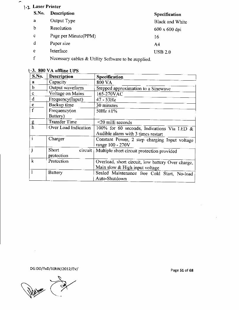
\, '2.. Laser PrinterS.No. Descriptiona Output Typeb Resolution
c Page per Minute(PPM)d Paper sizee Interface
f Necessary cables & Utility Software to be supplied.
SpecificationBlack and White600 x 600 dpi16
A4USB 2.0
\ .3. 800 VA offline UPSS.No. Descri tiona Ca acityb Out ut waveformc Voltage on Mainsd Fre uenc (In ut)e Backu timef Frequency(on
Batte )Transfer Time
h Over Load Indication
Charger
J Short circuitrotection
k Protection
Battery
DG:DD/TxD/IOkW /2012/EV /
S ecification800 VASte ed a roximation to a Sinewave165-270VAC47 - 53Hz30 minutes50Hz±l%
<20 milli seconds100% for 60 seconds, Indications Via LED &Audible alarm with 3 times restartConstant Power, 2 step charging Input voltagerange 100 - 270VMultiple short circuit protection provided
Overload, short circuit, low battery Over charge,Main slow & Hi h in ut volta eSealed Maintenance free Cold Start, No-loadAuto-Shutdown
Page 51 of 68
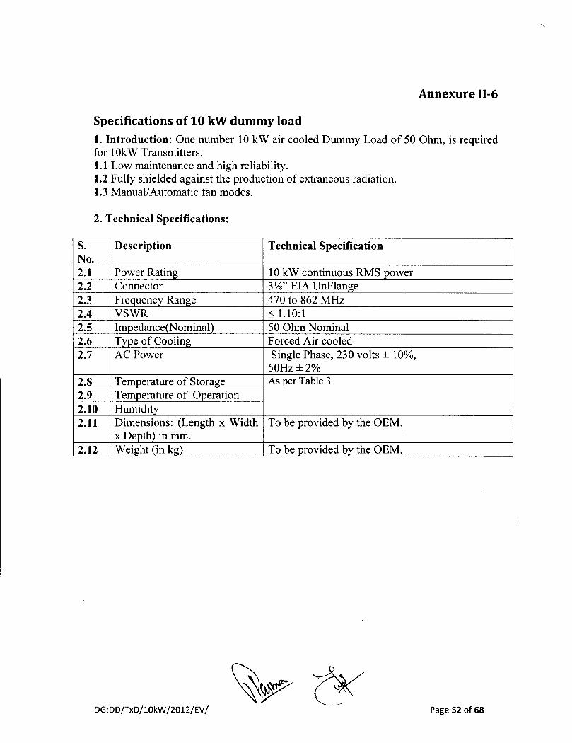
Annexure 11-6
Specifications of 10 kW dummy load1. Introduction: One number 10 kW air cooled Dummy Load of 50 Ohm, is requiredfor 10kW Transmitters.1.1 Low maintenance and high reliability.1.2 Fully shielded against the production of extraneous radiation.1.3 Manual! Automatic fan modes.
2. Technical Specifications:
S. Description Technical SpecificationNo.2.1 Power Rating 10k W continuous RMS power2.2 Connector 3W' EIA UnFlange2.3 Frequency Range 470 to 862 MHz2.4 VSWR ~1.10:12.5 Impedance(Nominal) 50 Ohm Nominal2.6 Type of Cooling Forced Air cooled2.7 AC Power Single Phase, 230 volts ± 10%,
50Hz±2%2.8 Temperature of Storage As per Table 32.9 Temperature of Operation2.10 Humidity2.11 Dimensions: (Length x Width To be provided by the OEM.
x Depth) in mm.2.12 Weight (in kg) To be provided by the OEM.
DG :DD/TxD/l0kW /2012/EV / Page 52 of 68

Annexure 11-7SPECIFICATIONS OF MEASURING EQUIPMENT:
A. Specifications of Colour test pattern & Tone generator
ec mca r>arame ers:S.No. Description Parametric values4.1 Power supply 230VAC±10%, 50 Hz ± 2%4.2 Output Connector - video/audio BNC/XLR4.3 Operating Temperature As per Table 34.4 Output Impedance - video/audio 750/1204.5 Video Output Return loss >30dB4.6 Video Test signals 75% & 100% colour bar,
linearity, flat field, Multiburst,sweep (upto 5 MHz), pulse & bar,CCIR Line 17, 18, 330, 331,video sweep for 250kHz to 5MHz etc.
4.7 Audio Level -48dBU to +12dBU (ResolutionIdB)
4.8 Audio Frequency o to 20 kHz
1. Doordarshan requires broadcast quality colour test pattern, sync signal generatorand tone generator with test signals for analog TV transmitters.2. It should work for PAL/625 line system.3. The unit should have SNMP remote control facility to integrate automated service.4 T h . I t
B. Specifications of RFAnalyser:
1. The RF Antenna Analyzer should be a precision portable instrument,suitable for making direct measurement and analysis on transmission linesof a "T.V. Transmitting antenna system" installed at a T.V. tower, inproximity of high radiation. It should be capable to perform coveragemapping, Spectrum Analysis, Field Strength measurement RF powermonitoring and provide GPS co-ordinates information. It should be a stand-alone integrated unit, rugged in construction, light weight, battery operated,portable and suitable to be used in tropical environment in open to air spaceon T.V. tower platforms.
2. Features and Measurements required:
1. VSWR and Return Loss
DG:DD/TxD/l0kW /2012/EV / Page 53 of 68

11. Cable Loss111. Gain, Loss or isolation of antenna and devices such as filters,
attenuators, amplifiers, etc.IV. Distance-to-Fault (DTF) using frequency domain reflectometry, with
facility of comparison of electrical length of two cables.v. Field Strength Measurements
VI. RF power measurementV11. Spectrum Analysis
V11l. GPS co-ordinateix. Phase Measurement
3. Technical Specifications:
3.1 Antenna Testing:i. Sweep Frequency Range: VHF Band III and UHF Band IVN Range
11. Freq. Resolution: :s 100KHz for the full frequency range so that thelevel corresponding to each TV channel can be measured.
111. Display Points: selectable from 150 to 2000 points (selectable) foraccurate measurement of Distance to Fault.
3.2 Measurement Range:1. VSWR: 1.00 to 6.00 (Resolution 0.01) or better
11. Return Loss: 0.00 to 50.00 dB (Resolution O.OldB) or better111. Cable Loss: 0.00 to 20.00dB (Resolution O.OldB) or betterIV. Distance to Fault Parameters: Horizontal Range: 0 to 1500 meters or
betterv. This instrument should have the facility to display 'Smith Chart' for
transmission lines.VI. The fault detection in a transmission line/cable with air and foam as
dielectric should be possible for minimum 600 meters over fullfrequency range.
V11. Dynamic Range:80dB or betterV11l. Directivity(corrected for vector errors): 42dB or better
IX. Test port available on analyser: N-type, 50 ohmsx. R.F. immunity: The analyser should be immune to strong R.F. field at
least upto +15dBm or betterXl. The built-in signal source should allow measurement of loss, gain or
isolation of devices such as filters, cables, attenuators, amplifiers andantennas.
XII. Maximum input level: +20dBm, ±50V dc or betterX11l. Phase measurement: Instrument should be able to make 1 port phase
measurement and display SII parameter on the instrument display.
3.3 Field Strength Measurement:i. The unit should have built-in Field Strength measurement capability
for television signals and shall be supplied with all the required
DG:DD/TxD/lOkW /2012/EV / Page 54 of 68

accessories such as standard calibrated omni-directional dipole/logperiodic antenna to cover both VHF and UHF frequency band,suitable tripod, pole, test port cable etc. Certificate of calibration forthe Antenna should be supplied along with the goods. Correctionfactor data should also be provided.
11. Frequency range: VHF Band III and UHF Band IVN Range111. Frequency resolution: better than 10HzIV. High stability oscillator: frequency stability ±1ppm or betterv. Level resolution: O.1dB
VI. EMF voltage measurement: should be possible to measure the EMFVoltage from -5dBIlV to +120dBIlV or better
Vll. Field Strength Measurement: should be possible to measure the fieldstrength from -5 dBIlV/m to +120dBIlV/m or better.
Vlli. Detection systems: Max Peak, RMS Average/Average value.IX. Detection Scale Units: dBIlV/m, dBm/m.x. Antenna type: Half wave standard dipole or log Periodic or any other
suitable standard antenna with tripod pole to have 10M height ofreceiving antenna and connecting cable of minimum 12 m should beoffered.
Xl. Received Signal strength mapping: Instrument should be able toperform coverage mapping using software supplied with the unit.
XlI. It should be possible to make field/Signal strength measurement inthe field stamped with GPS Coordinates and overlaid over the mapcaptured in the unit from Google Map using software supplied withthe unit. It should be possible to save the mapped results and transferto PC or Laptop using USB drive or LAN.
3.4 Spectrum Analysis and Power Measurement:
3.4.1 Frequency:
1. Frequency Range: 100KHz to 3.5GHz11. Frequency Tuning Resolution: 1Hz
111. Frequency Reference: Aging:S ±1ppm or better.Accuracy:S ± 2ppm or better.
IV. Frequency Span: 10Hz to 4GHz in 1-2-5 steps plus zero span mode.v. Resolution Bandwidth: 10Hz to 3MHz in 1-3 steps, Accuracy ±5%
VI. Video Bandwidth: 1Hz t03MHz in 1-3steps, Accuracy ±5%Vll. Selectivity(3dB): 10Hz (min)
Vlll. Level Resolution: O.ldBIX. SSB Phase Noise at 1GHz: better than :S-lOOdBcat 10KHz offsetx. Spurious Response: :S-90dBmfor frequencies 2: 10MHz.
Xl. Sweep time (full span): should be adjustable by the instrumentautomatically according to the RBW value selected and optimizedaccording to the signal applied for measurement.
DG :DD/TxD/10kW /2012/EV / Page 55 of 68

3.4.2 Amplitude
1. Measurement Range: -150dBm to +25dBm11. Protection against maximum input level: The instrument should have
internal protection against the maximum input level upto+35dBm(peak, continuous); ± 50V dc.
111. Average Noise Level: S-150dBm ( Frequency: >10MHz; RBW:10Hz, OdBattenuation.)
IV. Total Level Accuracy: ±1.25dB, ±1dB(typical) (over full frequencyrange)
v. Display Scale units: dBm, dBV, dBmV, dBIlV, IlV, mY, nW, IlW,mW and W.
VI. Display Range: 1 to 1OdB/division, in 1dB steps, 1Odivisiondisplay.V11. Detection System: RMS average, Positive Peak, Negative Peak,
Sample Mode, Quasi PeakVll1. Input Attenuator Range: 0 to +50dB.
IX. Channel Power Measurement: -120dBm to +25dBm at the coupledports of the transmitter.
3.5 GPS ReceiverThe instrument should have built-in GPS receiver to provide the Longitude,Latitude in six figure co-ordinates and Altitude in meters. It should bepossible to save the GPS information with trace in the internal memory.Suitable GPS antenna with min 5m cable should be offered.
4 General Features and Specifications1. Weight: To be specified by the OEM.
11. Temperature Range (for operation): As per table 3.111. Relative humidity (for operation) As per Table 3.IV. AMSL: As per Table 3.v. Power Supply: Operable on 230V ± 10% AC, 50Hz mains and 12
Volt dc/ chargeable battery, with back up of at least 3 hours, shouldalso have facility of charging from vehicle battery.
VI. Display: The analyser should have coloured LCD/TFT screen todisplay the measured traces.
Vll. The instrument should have multi-marker (min: 6) displayed on thescreen to see the return loss and VSWR at different frequenciessimultaneously.
DG :DD/TxD/IOkW /2012/EV / Page 56 of 68

Vlll. The segment limit lines feature should be available for pass-fail tests.IX. The instrument should have the spectral emission mask filter feature
to confirm the transmissions within the approved limits.x. Instrument should have limit line feature to create mask filter for
confirming measurements within threshold limits. If the appliedsignal exceeds the threshold limits, provision should be there toautomatically save the event into the internal memory of the unit. Itshould be possible to recall the saved results from memory to analysethe events of violation of threshold limits.
Xl. Instrument should be supplied with USB and LAN interface and therequired software for easy transfer of saved data into PC/Laptop andVIce-versa.
5 Plotter/printer:a) The analyser should have RJ 45 interface for printing on Deskjet/laser
printers and connecting with PCs.
b) Internal memory and Storage capacity: Minimum 2000 traces and2000 sets of instrument configurations.
6 Accessories and Options:a) All accessories/options required for measurement of VSWR, cable
loss, return loss and Distance to Fault of T.V. transmitting antennaand RF feeder cables, spectrum analysis, GPS and field strengthmeasurement are required to be quoted with the analyser.
b) Standard accessories to be supplied with the unit should be clearlyspecified in the offer.
c) Carrying case shall be offered for easy handling in the field and safertransportation and shall form part of the offer.
C. Specifications of Audio Analyser:
1. SCOPE:The Audio Analyzer should be a precision instrument, suitable for making
direct Audio measurements of a 'T.V. Transmitter system'. It should be capable tomonitor all the Audio parameters of an Analog TV Transmitter system.
2. Features and Measurements required:2.1 Analog Audio measurement functions: Instrument must have the facility tomeasure the following Analog audio parameters of an Analog TV Transmitter:
(i),Level(ii) Cross talk(iii) Frequency
DG:DD/TxD/l0kW /2012/EV / Page 57 of 68

(iv) Total Harmonic distortion(v) Noise(vi) Drift(vii) Inter modulation Distortion(viii) Narrow band selective level(ix) Spectral FFT analysis
3.0 Technical Specifications:-
SL. No. Parameters Values1.0 General Data1.1 Operating Temperature Range As per Table 31.2 Humidity As per Table 31.3 Power Supply 230V ± 10%2.0 Audio Inputs/Outputs2.1 Connectors BNC, two channels simultaneously operating.2.2 Frequency Range 10 Hz to 80 kHz.2.3 Frequency response from 20 ±0.05dB
Hz to 20 KHz. (Referenced to1 KHz)
2.4 Common Mode Rejection at 1 2: 75 dBKHz
2.5 Harmonic Distortion 20 Hz to 20 kHzFundamental Range
2.6 Maximum Input Voltage 33 Volt RMS
DG:DD/TxD/IOkW /2012/EV / Page 58 of 68

3. Connectors4. 1m edance5. VSWR
6. Accuracy
7. Insertion Loss8. RF In ut Power9. Construction10. Tern erature
Annexure 11-8MISC ITEMS FOR MONITORING AND MAINTENANCE:
A.Specifications of RF Step Attenuator (0 - 100 dB)S.No. Parameters Values1. Frequency Range DC-IGHz2. dB Value 0-100 dB in 1dB/1OdBsteps
(Fine/Coarse steps)3. Connectors BNC4. Impedance 50 Ohms5. VSWR 1.2:1 (DC-500MHz)
1.4:1 (500MHz-IGHz)6. Acc.uracy ± 0.2 dB (DC-500MHz)
± 0.3 dB (500MHz-IGHz)7. Insertion Loss 0.5dB upto 1 GHz8. RF input Power
Avg 2 WattPeak 1000W
9. Temperature As per Table 3
B.Specifications of RF Fixed Attenuator 3 dB, 6 dB, 12 dB (N type)S. No. Values1. DC-IGHz2. 3dB, 6dB, 12dB
(each one inde endentl )N e50 Ohms1.2:1 (DC-500MHz)1.4:1 500MHz-IGHz)± 0.2 dB (DC-500MHz)± 0.3 dB (500MHz-IGHz)0.5dB u to 1 GHz1 WattRug ed unibodyAs er Table 3
DG :DD/TxD/10kW /2012/EV / Page 59 of 68

Annexure 11-9
CBandjKu Band satellite receive equipment
A. Specifications of Professional IRDfor C-BandjKu-Band:1.1. General:
1.1.1. The IRD should have a front panel display and one should be able to enter oredit all the parameters for a perfect reception of the signals.
1.1.2. There should be provision for observing the BER (Pre & Post correction) forDVB-S and CIN or PER (for DVB-S2) of the signal and signal level in the frontpanel.
1.1.3. IRD should be able to descramble BISS mode I and BISS-E signals.1.1.4. IRD should have at least 10 memory setups to store channels.1.1.5. IRD should have CI slot so that by inserting the CAM module signals can be
descrambled.1.1.6. There should be a 60 unlock input to synchronise the IRD with external
reference video signal.
1.2. RF Parameters:
S. Parameter SpecificationNo.
a. Input Frequency Range 950 - 1750 MHzb. No. ofInputs I No.c. Tuning Step Size 125 KHz, maximumd. Satellite Frequency Band C- & Ku-Band, selectablee. Input Impedance 75 Ohmsf. Input Connector F-Type femaleg. Input Power Range -30 to -65 dBm per carrierh. Image Rejection >30 dBI. Input Return Loss 7 dB, minimumj. Noise Figure 20 dB, maximumk. AFC Tuning Range ±5 MHzI. De-Modulation Method DVB-S QPSK, DVB-S2 8PSK demodulationm Variable Symbol Rates 1.0 to 44.5 M symbol/See ( DVB-S)
1.5 to 30 M symbols/see, minimum (DVB-S2)
n. Convolution Inner FEC R= ~, 2/3, %,5/6, 7/8( DVB-S option) QPSKRates selectable R= 2/5, ~, 3/5, 2/3, %, 4/5,5/6,8/9,9/10
(DVB-S2)o. IF Filter Bandwidth Automatic Selection (dependent on Symbol
Rate)Note: ASI to SDI decompression should take place directly, i.e., not throughAnalog to Digital Converter. ~ ./
DG,DDfT,D/lOkW/2D12/EV/ ~7 ~/'" Pag.60 olGB

1.3 Audio and Video Decompression Parameters:
S. Parameter SpecificationNo.
Video Resolution (all 720 x 576, 704 x 576, 544 x 576, 480 xresolutions shall be 576, 352 x 576 (other standard resolutionscapable of I, P & B frame should be selectable)decoding)Video Decompression MP@MLTypeTelevision Standard PAL-BAudio Decompression MPEG-I Layer-II audio (Stereo/Type Musicam, i.e. Single Mono, Dual Mono,
Stereo, and Joint Stereo)16.1AC-3 Pass through
1.4 Transport Stream O/P: MPEG-2 DVB-ASI on BNC
1.5 Video Output Specifications:
1.5.1 Analog Video Output Specifications
S. Parameter SpecificationNo.(a) Connector Type BNC (75 Ohms)(b) Quantity 1No. of analog composite PAL-B CCIR
StandardI Level 1.6 V
p-p +/- 5%
1.5.2 Digital Video Output Specifications
S. Parameter SpecificationNo.(a) Connector Type BNC (75 Ohms)(b) Quantity 1No. of DIGITAL output
compliant to ITU-R BT.656Standard
I Level 800mV p-p for SDI(d) Serial Interface SMPTE 272-1994, 270 Mb/s (10
bit)1.5.3 Video Performance Specifications
DG:DD/TxD/10kW /2012/EV / Page 61 of 68

S. Parameter SpecificationNo.(a) Frequency Response Within 2 dB down at 5 MHz(b) Chroma-Luma Delay ±30 ns, maximumI Field Time Distortion <2%(d) Line Time Distortion < 1%(e) Short Time distortion <2%(f) Differential Gain <4%(g) Differential Phase < 2°(h) Signal to Noise Ratio >55 dB (luminance weighted)
1.5.4 VBI Signal Reinsertion Specifications:
S. Parameter SpecificationNo.
VBI Formats WSTSupported VITCRange of VBI lines Field I lines 7 to 22 (PAL) and
corresponding lines ofField 2Synchronisation with Within ± I frameVideoPreservation of line VBI data shall be reinserted on thenumbering original line number
1.6 Audio Output1.6.1 Analog Audio1.6.1.1 Each analog audio output shall be presented as a stereo pair.1.6.1.2 In the event of "Mono" transmissions, the same input channel will be output to both
left and right connectors.1.6.1.3 In other modes ("Stereo", "Joint Stereo" and "Dual Mono"), the two input channels
will be output as left and right.1.6.1.4 Means shall be provided to combine the left and right channels on the IRD output to
produce a mono output from stereo transmissions to accommodate those sites notequipped for stereo transmission.
1.6.2 Analog Audio Output Specifications
S. Parameter SpecificationNo.(a) Output Impedance 6000 (balanced)(b) Number of Outputs 4, configurable as Stereo, Joint
Stereo, Single mono, Dual mono.I Connector Type XLR Male Socket or with suitable
XLR Adopter (i.e., no terminalblock)
Page 62 of 68

S. Parameter SpecificationNo.(a) Output level 2-7 Volts nominal(b) Output Format AES/EBUI Load Impedance 110 Ohms(d) Connector Type XLR Male Socket or with suitable
XLR Adopter (i.e., no terminalblock)
(e) Number of Outputs 2, Stereo Channels
1.6.4 Audio Performance Specifications at 256 Kbps and sampling rate of 48 KHz
S. Parameter SpecificationNo.(a) Peak Output Level + 18 dBm into 6000 balanced(b) Clipping Level S/W Selectable to be provided or
any preset value between +18dButo +25 dBu.
I Sampling Rates 48 KHz(d) Frequency Response 40 Hz to 20 kHz ± 2 dB(e) THD <0.3 % at 1 kHz(t) Dynamic range 80 dB (ITU-R1Arm weighting)(g) Crosstalk at 1 kHz 60 dB, full scale (20 Hz to 20 kHz)(h) Signal to noise ratio 55 dB (min) at 0 dBm
1.6.5 LNB Power Supply & Control
S.No. Parameter Soecification(a) LNB Voltage + 13 V (Vertical)/18 V (Horz)
polarizations switching or 19 V fixed.(b) Power Consumption 400 mA. (Max.)I Over Current protection Fold back current limiting.(d) LNB Power Supply & Control Receive Polarization Control by
electrical Command Via LNB-IFfeeder (High & Low band switchingPulse for Ku Band operation).
1.6.6 Size - Mount: 19" rack mountable.
B. Specifications of Cables, connecters2.1 An interconnecting low loss cable of length of 75 meters is required with each IRD with
suitable F male connector at each end.
2.2 The cable should be quoted in denomination of 50m & 25m, which can be usedindependently (i.e. as 50m or 25m) or collectively i.e. as a 75m length using a coupler(I-Connector) in between the 50m & 25m cables between outdoor and indoor units.
2.3 The total insertion Loss for cable should not exceed 15dB at 1450 MHz.
DG :DD/TxD/10kW /20l2/EV / Page 63 of 68

C. Specifications for the LNBCin Cband2.4 Technical Specifications:
S.No. Parameter Specification(a) Input frequency range 3.4 GHz to 4.2 GHz
(b) Local Oscillator frequency 5.150 GHz(c) L.O. Stability ±10 PPM
L.O. Phase noise Better than 65 dBclHz @ IkHzBetter than 80 dBclHz @ 10kHz (min)Better than 90 dBclHz (ciJ 100kHz (min)(d) Output frequency 950 MHz to 1450 MHz
(e) Conversion gain 55 dB (min.)
(f) Gain response Better than ± IdB/40 MHz(g) Output level at IdB 6dBmcompression point
(h) Output Connector F type female(i) Input VSWR/Output VSWR Better than 2.5: IU) Noise Temperature Better than 30deg K(k) Power supply requirement Should work between + 15V to +24V(I) Input flange CPR 229(m) Lightening/Surge protection Should be provided
2.5 LNBC should be environmentally sealed against weather conditions and extremes oftemperature (as mentioned in Table 3). LNBC should also be 100% water proof.
D. Specifications for Ku Band Feed, Cable, Dish, and LNBC1. Specifications for Cables & Connectors
a. An interconnecting low loss cable of length of 75 meters the cable should bequoted in denomination of 50m & 25m, which can be used independently (i.e.as 50m or 25m) or collectively i.e. as a 75m length using a coupler (1-Connector) in between the 50m & 25m cables between outdoor and indoorunits with F male connector at both ends.
b. The total insertion Loss for cable should not exceed 15dB at 1450 MHz.
2. Specifications for Parabolic Dish Antenna, solid type, 2.4 M (dia) andFeed
DG:DD/TxD/10kW /2012/EV /Page 64 of 68

S. No. Parameter Specification
1. Antenna type Offset / Prime Focus2. Frequency 10.95 GHz to 12.75 GHz
3. Size 2.4 m diameter
4. 3dB beamwidth Better than 10
5. Antenna Noise At 30°El: 31K (min)Temperature
6. Gain at 12.7 Min 47 ± 0.25dBiGHz
7. Drive system Manualsteerability
8. Azimuth 0 to 360°continuous with fineadjustments
9. Elevation 10 deg to 85 deg10 Polarization Linear orthogonal11 Mount option Ground mounting assembly to be
provided.Mount should be powder coated/hot dip galvanized.
12 Reflector Glass fiber reinforced polyesterMaterial
13 Wind loading 80 Km/h operational, 200 Km/hsurvival
14 Feed VSWR better than 1.3 : 115 Ports 2 port, for receiving both linear and
Orthogonal polarization signals16 Polarization 30 dB ( min ) on axis
discrimination17 Polarization -5degree to 95 degree
Adjustment
3. Specification for the Digital LNBC in Ku band
S. No. Parameter Specification
a) Input frequency 10.7 GHz to 12.2 GHz (See note givenrange below)
b) Local Oscillator LO freq of LNBC should be capable tofrequency provide output frequency in L Band
between 950 to 2150 MHz.
DG:DD/TxD/10kW /2012/EV / Page 65 of 68

c) L.a. Stability ± 25 KHz or better
L.a. Phase noise Better than 75 dBc/Hz @ 1kHz
d) Conversion gain 55 dB (min)
e) Output level at 5 dBm (min)IdB compressIOnpoint
f) Output Connector F type female
g) Input Better than 2.3: IVSWR/OutputVSWR
h) Noise Figure I dB (Max)
i) Power supply Should work between + 15V to +24Vrequirement with current consumption of about 300
mA (max)
j) Input flange WR 75
k) LNBC should be environmentally sealed against weatherconditions and extremes of temperature (as mentioned inTable 3) LNBC should also be 100% water proof.
NOTE: Bidder may offer 2 LNBCs or 3 LNBCs in one set (1 No. foreach band) to cover entire frequency ranf!e.
DG:DD/TxD/lOkW /2012/EV / Page 66 of 68

Annexure 11-10
Specification for RFPower Meter with Sensors
SCOPE:
The RF power meter is required for measurement of RF power of modulatedsignal. It should be a sensor based power measurement device having a good dynamicrange. The equipment should be rugged in construction, light weight and easy tooperate. The equipment must be supplied with the accessories like power cord, fusesand manuals.
Technical Specifications:
Temperature As per Table 3
S.No.1.2.
3.
3.
4.5.6.7.
Temperature
ValuesAvera e ower-67dBm to +44 dBm
s er second
The RF Power meter must be supplied with the power sensors to measure thepower in the above specified range.
DG :DD/TxD/10kW /2012/EV / Page 67 of 68

Annexure III
Indicative Sketch for 10kW (1+1) Transmitter System at one location
~
' lullinl: ~ ~)-{)lVfA-2, fem,1lD,
----------------------------------------------------------------- r-----------------------------------------------~: Setal Input Equipment : : :
(~/',~: --- :: :'J-,:) I VfA-t Ll}-O ___' : 10kW UHFTVTx1 :. I '- .• ~ ""\ r~' :VIlA and ...,.r--\.-- I I
Do: AIlA: 1F~5W111
k}{} IN' ::,: _~////:t~~.:,:-(.)~)-- ~ ....•.
•.....••.• from .... . \ ()! VDAand I' ••••••••qus IIlD5 -(H) ~ J" AIlA -0-(' ' : '
-0-0, 1OkWUHFTVTx2,, Video ••••••• tEstqus:~ :). ': -t,~'"" ,I :•••, ..'
! ': ~; .1. •. L.•.•. •. .' _ ~
, IFfromTx ---I ~ 1 1V ~ ToVideoPilll:h~•••••••••••ill.Part
___ ~ ToAuclioPilll:hhnel
,
,--------------------------------------------------------_.----------------,---------------
Fran/luJo/VideoPab:hPanel
{HJI WfM
.. UD~t2-{)-(l- lIoi!;)fwlnput-
0u1putMlIniIDffIIilI
N•• : L AD iDpol md_ •••••it-••••• g eqoipa.mt 3R: tobe winld.in 19'" Rac:k.. 1VRa:c:ivas 3R: DOt to beiasbD.c:d.in Rac:k..2.AcbWIDctailc:d SigutFlow Diagma. of the systemoffaallllll5t be indodc:d .inthe Tc:dmial bid.
DG:DD/TxD/l0kW /2012/EV / Page 68 of 68