
HMT100 User's Guide in English
52
USER'S GUIDE Vaisala HUMICAP ® Humidity and Temperature Transmitter Series HMT100 M210701EN-D
Transcript of HMT100 User's Guide in English

USER'S GUIDE
Vaisala HUMICAP® Humidity and Temperature Transmitter Series
HMT100
M210701EN-D

PUBLISHED BY
Vaisala Oyj Phone (int.): +358 9 8949 1 P.O. Box 26 Fax: +358 9 8949 2227 FI-00421 Helsinki Finland
Visit our Internet pages at http://www.vaisala.com/
© Vaisala 2009
No part of this manual may be reproduced in any form or by any means, electronic or mechanical (including photocopying), nor may its contents be communicated to a third party without prior written permission of the copyright holder.
The contents are subject to change without prior notice.
Please observe that this manual does not create any legally binding obligations for Vaisala towards the customer or end user. All legally binding commitments and agreements are included exclusively in the applicable supply contract or Conditions of Sale.
________________________________________________________________________________
VAISALA ________________________________________________________________________ 3
Table of Contents
CHAPTER 1 GENERAL INFORMATION............................................................................ 6
About This Manual ................................................................... 6 Version Information ............................................................... 6 Related Manuals ................................................................... 6 General Safety Considerations ............................................. 7 Feedback............................................................................... 7
Product Related Safety Precautions ...................................... 7 ESD Protection ......................................................................... 7 Recycling .................................................................................. 8 Patent Notice ............................................................................ 8 Trademarks ............................................................................... 9 License Agreement .................................................................. 9 Warranty.................................................................................... 9
CHAPTER 2 PRODUCT OVERVIEW................................................................................ 11
Introduction to the HMT100 Humidity and Temperature Transmitter.............................................................................. 11
Fixed and Remote Probe Models ....................................... 12 Optional Display .................................................................. 12 HMT100 Transmitter Components...................................... 12
CHAPTER 3 INSTALLATION............................................................................................ 15
Mounting ................................................................................. 15 Wall Mounting ..................................................................... 15
With Plastic Wall Assembly Plate (Provided)................. 15 With Optional Aluminum Wall Installation Plate............. 16
Installation with Rain Shield ................................................ 17 Installation with Radiation Shield ........................................ 18 Duct Installation Kit ............................................................. 19
Probe Assembly with Duct Installation Kit ..................... 20 Drilling Instructions for Duct Installation Kit ................... 21
Connections............................................................................ 22
CHAPTER 4 MAINTENANCE ........................................................................................... 25
Replacing the HUMICAP® Sensor......................................... 25 Fixed Probe Model .............................................................. 25 Remote Probe Model .......................................................... 25
Removing and Fastening the Probe..................................... 26 Fixed Probe Model .............................................................. 26 Remote Probe Model .......................................................... 27
User's Guide ______________________________________________________________________
4 ___________________________________________________________________ M210701EN-D
Calibration and Adjustment...................................................28 Relative Humidity Adjustment Using Push Buttons.............28 Adjustment with HM70 ........................................................29
Field Checking and Adjustment Using a Calibrated Reference Probe ............................................................30 One-Point Adjustment Using a Calibrator ......................31 Two-Point Adjustment Using a Calibrator ......................32 LiCl-NaCl Adjustment .....................................................32 Temperature Field Check and Adjustment by Using a Calibrated Reference Probe...........................................33
Adjustment with HMI41 .......................................................34 Connections and Selecting the Calibrator Function.......35 Offset and Gain Adjustments .........................................36
HMI41 as a Reference Meter ....................................36 HMI41 as a Terminal.................................................37
Troubleshooting..............................................................39 Analog Output Tests ..............................................................40
CHAPTER 5 TROUBLESHOOTING..................................................................................41
Error Mode...............................................................................41 Current Output.....................................................................41 Voltage Output.....................................................................41
Technical Support ..................................................................41 Return Instructions ................................................................42 Vaisala Service Centers .........................................................43
CHAPTER 6 TECHNICAL DATA ......................................................................................45
Specifications .........................................................................45 Dimensions in mm (inches)...................................................49
________________________________________________________________________________
VAISALA ________________________________________________________________________ 5
List of Figures Figure 1 HMT100 Components .............................................................. 13 Figure 2 Plastic Wall Assembly Plate (Spare Part No. GM45160)......... 15 Figure 3 Plastic Wall Assembly Plate with Aluminum Installation Plate. 16 Figure 4 Installation with Rain Shield (Spare Part No. 215109)............. 17 Figure 5 Installation of the Humidity Probe with the Radiation Shield.... 18 Figure 6 Probe Installation with the Duct Installation Kit ........................ 19 Figure 7 Assembly of the Humidity Probe with the Duct Installation Kit. 20 Figure 8 Drilling Instructions ................................................................... 21 Figure 9 HMT100 Connection Board...................................................... 22 Figure 10 (1) Isolated Current-Loop Wiring, (2) Voltage Output Wiring ... 23 Figure 11 Removing the Humidity Probe (Fixed Probe Model)................ 26 Figure 12 Removing the Humidity Probe (Remote Probe Model)............ 27 Figure 13 Adjustment Buttons .................................................................. 28 Figure 14 Location of the MI70 Probe and Cable Connector Ports ......... 29 Figure 15 Example of the MI70 Adjustment Menu ................................... 31 Figure 16 Example of the MI70 Adjustment Mode Graph Display ........... 31 Figure 17 Location of the HMI41 Calibration Connector .......................... 34 Figure 18 Accuracy of Temperature Measurement.................................. 46 Figure 19 Dimensions HMT100 Fixed Probe Model ................................ 49 Figure 20 Dimensions HMT100 Remote Probe Model............................. 50
List of Tables Table 1 Manual Revisions ....................................................................... 6 Table 2 Related Manuals ........................................................................ 6 Table 3 Wiring Table ............................................................................. 23 Table 4 Common Problems During Adjustment and Their Remedies .. 39 Table 5 Relative Humidity Measurement Specifications....................... 45 Table 6 Temperature Measurement Specifications .............................. 45 Table 7 Dewpoint Temperature (Calculated) Measurement
Specifications ........................................................................... 46 Table 8 Accuracy of Dewpoint Temperature Measurement.................. 46 Table 9 Operating Environment Specifications ..................................... 46 Table 10 Inputs and Outputs ................................................................... 47 Table 11 Mechanics Specifications......................................................... 47 Table 12 Options and Accessories.......................................................... 48
User's Guide ______________________________________________________________________
6 ___________________________________________________________________ M210701EN-D
CHAPTER 1
GENERAL INFORMATION
This chapter provides general notes for the manual and the product.
About This Manual This manual provides information for installing, operating, and maintaining the Humidity and Temperature Transmitter HMT100.
Version Information
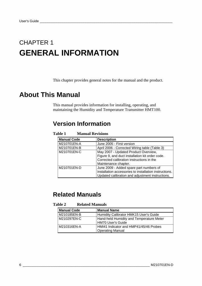
Table 1 Manual Revisions Manual Code Description M210701EN-A June 2005 - First version M210701EN-B April 2006 - Corrected Wiring table (Table 3) M210701EN-C May 2007 - Updated Product Overview,
Figure 9, and duct installation kit order code. Corrected calibration instructions in the Maintenance chapter.
M210701EN-D June 2009 - Added spare part numbers of installation accessories to installation instructions. Updated calibration and adjustment instructions.
Related Manuals
Table 2 Related Manuals Manual Code Manual Name M210185EN-B Humidity Calibrator HMK15 User's Guide M210297EN-C Hand-held Humidity and Temperature Meter
HM70 User's Guide M210316EN-A HMI41 Indicator and HMP41/45/46 Probes
Operating Manual

Chapter 1 ________________________________________________________ General Information
VAISALA ________________________________________________________________________ 7
General Safety Considerations
Throughout the manual, important safety considerations are highlighted as follows:
WARNING Warning alerts you to a serious hazard. If you do not read and follow instructions very carefully at this point, there is a risk of injury or even death.
CAUTION Caution warns you of a potential hazard. If you do not read and follow instructions carefully at this point, the product could be damaged or important data could be lost.
NOTE Note highlights important information on using the product.
Feedback
Vaisala Customer Documentation Team welcomes your comments and suggestions on the quality and usefulness of this publication. If you find errors or have other suggestions for improvement, please indicate the chapter, section, and page number. You can send comments to us by e-mail: [email protected]
Product Related Safety Precautions The Humidity and Temperature Transmitter HMT100 delivered to you has been tested for safety and approved as shipped from the factory. Note the following precautions:
CAUTION Do not modify the unit. Improper modification can damage the product or lead to malfunction.
ESD Protection Electrostatic Discharge (ESD) can cause immediate or latent damage to electronic circuits. Vaisala products are adequately protected against

User's Guide ______________________________________________________________________
8 ___________________________________________________________________ M210701EN-D
ESD for their intended use. However, it is possible to damage the product by delivering electrostatic discharges when touching, removing, or inserting any objects inside the equipment housing.
To make sure you are not delivering high static voltages yourself:
- Handle ESD sensitive components on a properly grounded and protected ESD workbench. When this is not possible, ground yourself to the equipment chassis before touching the boards. Ground yourself with a wrist strap and a resistive connection cord. When neither of the above is possible, touch a conductive part of the equipment chassis with your other hand before touching the boards.
- Always hold the boards by the edges and avoid touching the component contacts.
Recycling
Recycle all applicable material.
Dispose of batteries and the unit according to statutory regulations. Do not dispose of with regular household refuse.
Patent Notice The HMT100 is protected by the following patents and their corresponding national rights:
Finnish patent 98861, French patent 6650303, German patent 69418174, Japanese patent 3585973, UK patent 0665303, U.S. patent 5607564.
Chapter 1 ________________________________________________________ General Information
VAISALA ________________________________________________________________________ 9
Trademarks
HUMICAP is a registered trademark of Vaisala Oyj.
License Agreement All rights to any software are held by Vaisala or third parties. The customer is allowed to use the software only to the extent that is provided by the applicable supply contract or Software License Agreement.
Warranty
For certain products Vaisala normally gives a limited one-year warranty. Please observe that any such warranty may not be valid in case of damage due to normal wear and tear, exceptional operating conditions, negligent handling or installation, or unauthorized modifications. Please see the applicable supply contract or Conditions of Sale for details of the warranty for each product

User's Guide ______________________________________________________________________
10 __________________________________________________________________ M210701EN-D
This page intentionally left blank.
Chapter 2 __________________________________________________________ Product Overview
VAISALA _______________________________________________________________________ 11
CHAPTER 2
PRODUCT OVERVIEW
Thank you for choosing the Vaisala HUMICAP® Humidity and Temperature Transmitter Series HMT100. This chapter introduces you to its features.
The Vaisala range of relative humidity measurement instruments covers all the applications from ventilation to process control in demanding explosive areas. For more information about other Vaisala relative humidity instruments, please contact your Vaisala representative or visit www.vaisala.com.
Introduction to the HMT100 Humidity and Temperature Transmitter
The Vaisala HUMICAP® Humidity and Temperature Transmitter Series HMT100 measures relative humidity, temperature and dewpoint. It is powered with a 10 ... 35 VDC or 24 VAC input voltage and it outputs an analog signal of either 4 ... 20 mA, 0 ... 1 V, 0 ... 5 V or 0 ... 10 V.
The HMT100 transmitter can be configured to output either one or two quantities, in the following combinations:
- simple RH transmitter
- simple Td transmitter
- RH and T transmitter
- Td and T transmitter
The output quantities and the analog signal type (current or voltage output) are set during order time, and cannot be changed later by the user.
The following accessories are optionally available:
- Wall installation plate (aluminium)
- Duct installation kit
- Rain shield with installation kit
- Rain/solar radiation shield installation kit (for pole installation)
User's Guide ______________________________________________________________________
12 __________________________________________________________________ M210701EN-D
Fixed and Remote Probe Models
The HMT100 is available either with a fixed probe (0.1 m probe cable) or a remote probe with different cable lengths (3/5/10 m cable lengths. A 10 m extension cable is also available; see Table 12 Options and Accessories on page 48).
The HMP100 relative humidity probe used in the HMT100 transmitter is fully interchangeable. You can easily remove the probe and replace it with a new one without having to adjust the transmitter.
Optional Display
The HMT100 is also available with an optional one-line display. The display shows the measurement results of selected parameters in selected units (selected at the time of ordering). The parameters are displayed in turns one at a time. The display backlight is turned on and off with a jumper on the transmitter electronics motherboard.
HMT100 Transmitter Components
Figure 1 on page 13 illustrates the main features of HMT100. On the left is a remote probe model without display, and on the right is a fixed probe model with the optional display. The numbers and arrows indicate the main components of the transmitters.

Chapter 2 __________________________________________________________ Product Overview
VAISALA _______________________________________________________________________ 13
0603-048
Figure 1 HMT100 Components
The following numbers refer to Figure 1 above:
1 = Transmitter housing; transmitter cover 2 = Probe cover 3 = Probe cable 4 = HMP100 probe 5 = Filter
See Table 12 on page 48 for spare part numbers.

User's Guide ______________________________________________________________________
14 __________________________________________________________________ M210701EN-D
This page intentionally left blank.

Chapter 3 _______________________________________________________________ Installation
VAISALA _______________________________________________________________________ 15
CHAPTER 3
INSTALLATION
Mounting
Wall Mounting
With Plastic Wall Assembly Plate (Provided)
1. Attach the wall assembly plate to the wall with two screws.
2. Press the transmitter down so that it slides along the rails of the mounting plate.
0505-171
Figure 2 Plastic Wall Assembly Plate (Spare Part No. GM45160)
User's Guide ______________________________________________________________________
16 __________________________________________________________________ M210701EN-D
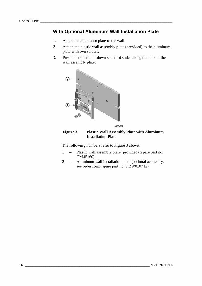
With Optional Aluminum Wall Installation Plate
1. Attach the aluminum plate to the wall.
2. Attach the plastic wall assembly plate (provided) to the aluminum plate with two screws.
3. Press the transmitter down so that it slides along the rails of the wall assembly plate.
0505-339
Figure 3 Plastic Wall Assembly Plate with Aluminum Installation Plate
The following numbers refer to Figure 3 above:
1 = Plastic wall assembly plate (provided) (spare part no. GM45160)
2 = Aluminum wall installation plate (optional accessory, see order form; spare part no. DRW010712)

Chapter 3 _______________________________________________________________ Installation
VAISALA _______________________________________________________________________ 17
Installation with Rain Shield
The installation kit with rain shield includes a metal mounting plate and a rain shield for the transmitter. Vaisala order code: 215109.
0505-340
Figure 4 Installation with Rain Shield (Spare Part No. 215109)
1. Fasten the metal mounting plate to the wall or pole with screws (see Figure 4 above). Note the arrow on the mounting plate. Attach the mounting plate with the arrow pointing upwards.
2. Fasten the plastic wall assembly plate (provided) to the metal mounting plate with three screws.
3. Fasten HMT100 Humidity and Temperature Transmitter to the wall assembly plate by pressing the transmitter down so that it slides along the rails of the mounting plate.
4. Fasten the rain shield to the metal mounting plate with two (M6) mounting screws.
NOTE Remove the rain shield before taking out the HMT100.
User's Guide ______________________________________________________________________
18 __________________________________________________________________ M210701EN-D
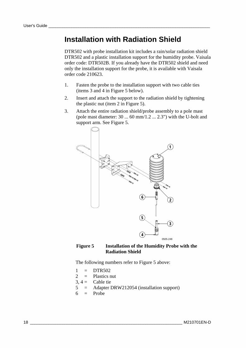
Installation with Radiation Shield
DTR502 with probe installation kit includes a rain/solar radiation shield DTR502 and a plastic installation support for the humidity probe. Vaisala order code: DTR502B. If you already have the DTR502 shield and need only the installation support for the probe, it is available with Vaisala order code 210623.
1. Fasten the probe to the installation support with two cable ties (items 3 and 4 in Figure 5 below).
2. Insert and attach the support to the radiation shield by tightening the plastic nut (item 2 in Figure 5).
3. Attach the entire radiation shield/probe assembly to a pole mast (pole mast diameter: 30 ... 60 mm/1.2 ... 2.3") with the U-bolt and support arm. See Figure 5.
1
2
3
4
5
6
0505-248
Figure 5 Installation of the Humidity Probe with the Radiation Shield
The following numbers refer to Figure 5 above:
1 = DTR502 2 = Plastics nut 3, 4 = Cable tie 5 = Adapter DRW212054 (installation support) 6 = Probe
Chapter 3 _______________________________________________________________ Installation
VAISALA _______________________________________________________________________ 19
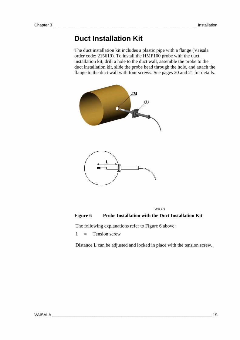
Duct Installation Kit
The duct installation kit includes a plastic pipe with a flange (Vaisala order code: 215619). To install the HMP100 probe with the duct installation kit, drill a hole to the duct wall, assemble the probe to the duct installation kit, slide the probe head through the hole, and attach the flange to the duct wall with four screws. See pages 20 and 21 for details.
24
L
1
0505-176
Figure 6 Probe Installation with the Duct Installation Kit
The following explanations refer to Figure 6 above:
1 = Tension screw Distance L can be adjusted and locked in place with the tension screw.
User's Guide ______________________________________________________________________
20 __________________________________________________________________ M210701EN-D
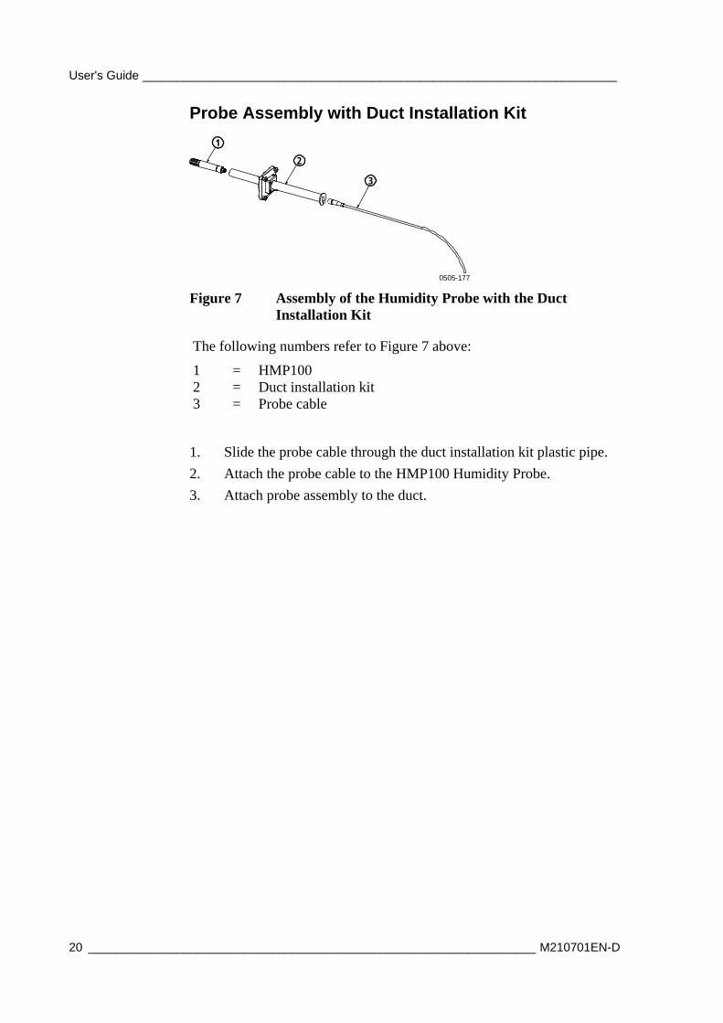
Probe Assembly with Duct Installation Kit
2
1
3
0505-177
Figure 7 Assembly of the Humidity Probe with the Duct Installation Kit
The following numbers refer to Figure 7 above:
1 = HMP100 2 = Duct installation kit 3 = Probe cable
1. Slide the probe cable through the duct installation kit plastic pipe.
2. Attach the probe cable to the HMP100 Humidity Probe.
3. Attach probe assembly to the duct.

Chapter 3 _______________________________________________________________ Installation
VAISALA _______________________________________________________________________ 21
Drilling Instructions for Duct Installation Kit
42
1
2
3
Ø24Ø3.2
0505-178
Figure 8 Drilling Instructions
The following numbers refer to Figure 8 above:
1 = Mounting screw 2 = Tension screw 3 = HMP100 assembled in duct installation kit plastic pipe
Drill the holes for the duct installation kit as follows:
1. Use a 24-mm drill bit to drill a hole to the duct wall for the humidity probe.
2. Drill holes for the duct installation kit mounting screws around the hole in a square arrangement, 42 mm apart from each other. Use a 3.2-mm drill bit to drill the holes for the mounting screws (four ST4.2×16-C-Z DIN 7981 screws).
User's Guide ______________________________________________________________________
22 __________________________________________________________________ M210701EN-D
Connections
0505-179
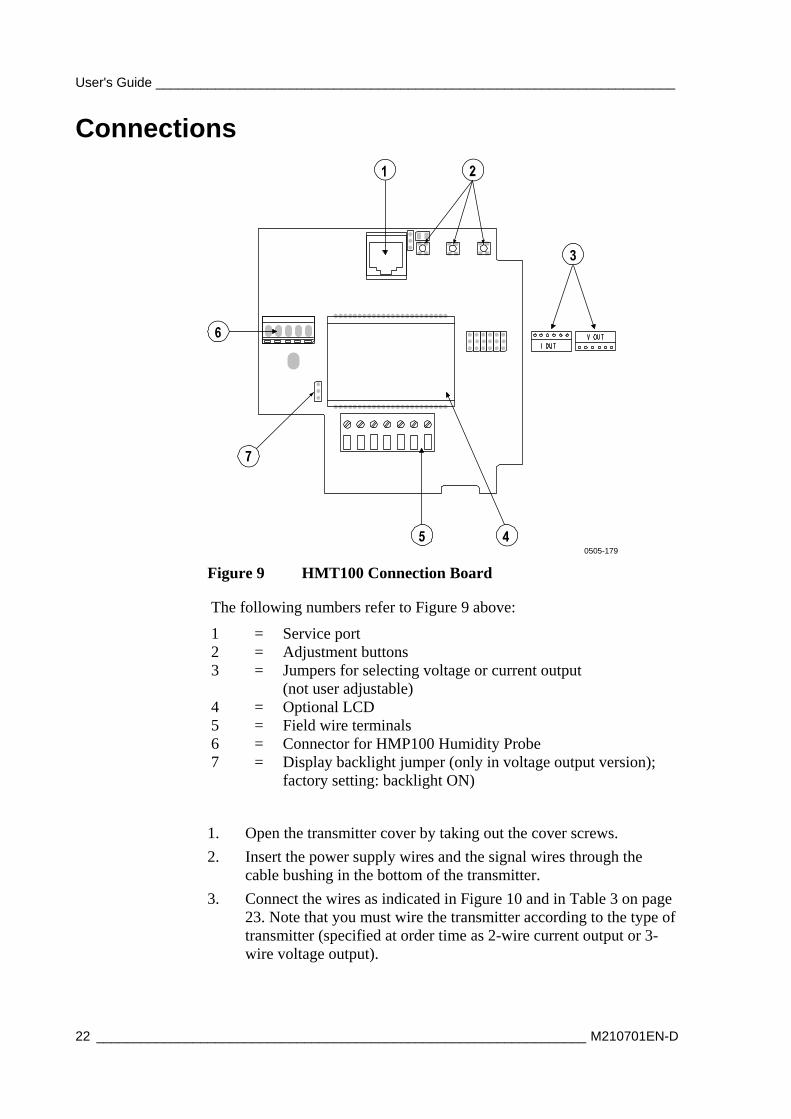
Figure 9 HMT100 Connection Board
The following numbers refer to Figure 9 above:
1 = Service port 2 = Adjustment buttons 3 = Jumpers for selecting voltage or current output
(not user adjustable) 4 = Optional LCD 5 = Field wire terminals 6 = Connector for HMP100 Humidity Probe 7 = Display backlight jumper (only in voltage output version);
factory setting: backlight ON)
1. Open the transmitter cover by taking out the cover screws.
2. Insert the power supply wires and the signal wires through the cable bushing in the bottom of the transmitter.
3. Connect the wires as indicated in Figure 10 and in Table 3 on page 23. Note that you must wire the transmitter according to the type of transmitter (specified at order time as 2-wire current output or 3-wire voltage output).
Chapter 3 _______________________________________________________________ Installation
VAISALA _______________________________________________________________________ 23
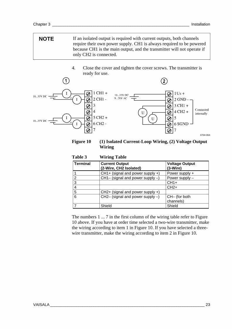
NOTE If an isolated output is required with current outputs, both channels require their own power supply. CH1 is always required to be powered because CH1 is the main output, and the transmitter will not operate if only CH2 is connected.
4. Close the cover and tighten the cover screws. The transmitter is
ready for use.
0704-064
Figure 10 (1) Isolated Current-Loop Wiring, (2) Voltage Output Wiring
Table 3 Wiring Table Terminal Current Output
(2-Wire, CH2 Isolated) Voltage Output (3-Wire)
1 CH1+ (signal and power supply +) Power supply + 2 CH1– (signal and power supply –) Power supply – 3 CH1+ 4 CH2+ 5 CH2+ (signal and power supply +) 6 CH2– (signal and power supply –) CH– (for both
channels) 7 Shield Shield
The numbers 1 ... 7 in the first column of the wiring table refer to Figure 10 above. If you have at order time selected a two-wire transmitter, make the wiring according to item 1 in Figure 10. If you have selected a three-wire transmitter, make the wiring according to item 2 in Figure 10.

User's Guide ______________________________________________________________________
24 __________________________________________________________________ M210701EN-D
This page intentionally left blank.
Chapter 4 ______________________________________________________________ Maintenance
VAISALA _______________________________________________________________________ 25
CHAPTER 4
MAINTENANCE
This chapter provides information that is needed in basic maintenance of the product.
Replacing the HUMICAP® Sensor
Fixed Probe Model
1. The end of the plastic probe cover is detachable. Carefully turn the end about 1/6 of a turn to loosen it. Remove the end of the probe cover and the filter.
2. Remove the damaged sensor and insert a new one.
3. Recalibrate the transmitter.
4. Replace a dirty filter to ensure a maximum lifetime and a fast response for the sensor. Do not attempt to clean the filter.
Remote Probe Model
1. Remove the filter (plastic grid or sintered stainless steel).
2. Remove the damaged sensor and insert a new one.
3. Recalibrate the transmitter.
4. Replace a dirty filter to ensure a maximum lifetime and a fast response for the sensor. Do not attempt to clean the filter.
User's Guide ______________________________________________________________________
26 __________________________________________________________________ M210701EN-D
Removing and Fastening the Probe
Fixed Probe Model
2
1
3
4
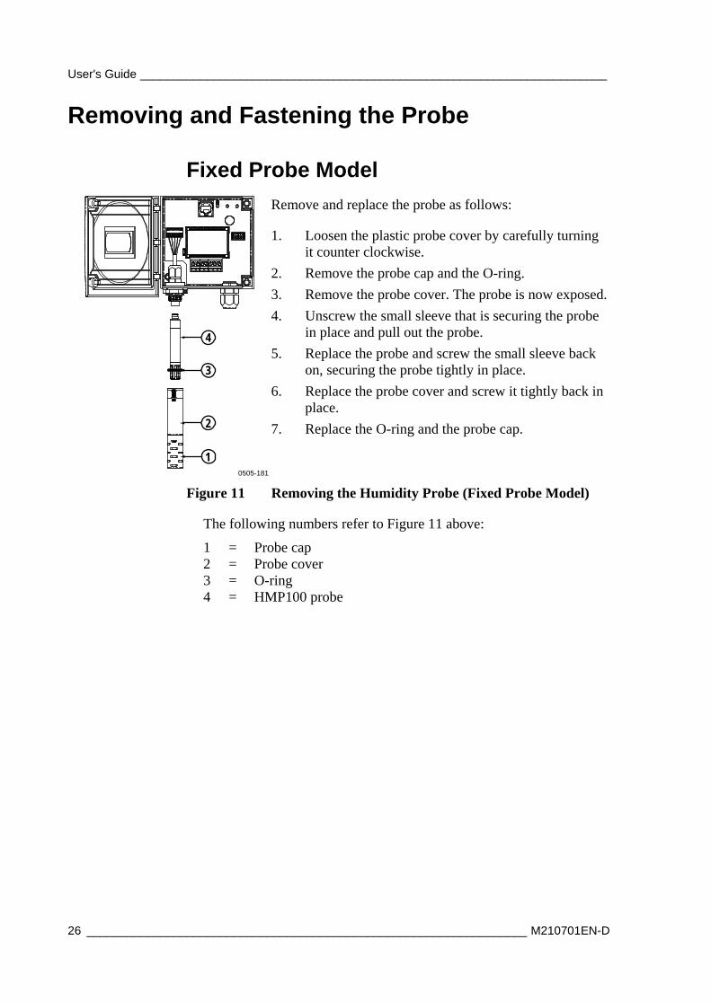
Remove and replace the probe as follows:
1. Loosen the plastic probe cover by carefully turning it counter clockwise.
2. Remove the probe cap and the O-ring.
3. Remove the probe cover. The probe is now exposed.
4. Unscrew the small sleeve that is securing the probe in place and pull out the probe.
5. Replace the probe and screw the small sleeve back on, securing the probe tightly in place.
6. Replace the probe cover and screw it tightly back in place.
7. Replace the O-ring and the probe cap.
0505-181
Figure 11 Removing the Humidity Probe (Fixed Probe Model)
The following numbers refer to Figure 11 above:
1 = Probe cap 2 = Probe cover 3 = O-ring 4 = HMP100 probe
Chapter 4 ______________________________________________________________ Maintenance
VAISALA _______________________________________________________________________ 27
Remote Probe Model
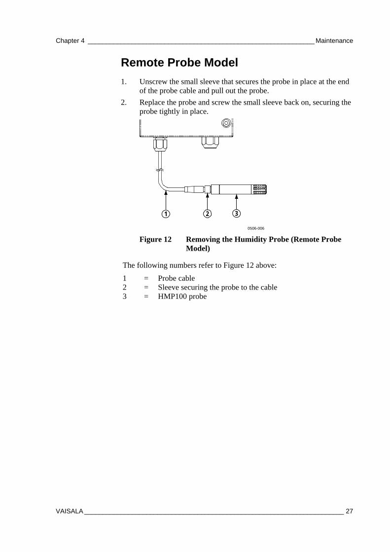
1. Unscrew the small sleeve that secures the probe in place at the end of the probe cable and pull out the probe.
2. Replace the probe and screw the small sleeve back on, securing the probe tightly in place.
1 32
0506-006
Figure 12 Removing the Humidity Probe (Remote Probe Model)
The following numbers refer to Figure 12 above:
1 = Probe cable 2 = Sleeve securing the probe to the cable 3 = HMP100 probe
User's Guide ______________________________________________________________________
28 __________________________________________________________________ M210701EN-D
Calibration and Adjustment Calibrate and adjust the HMT100 using the push-buttons on the motherboard or with portable humidity meters HM70 or HMI41.
A calibrator kit is needed for calibration against saturated salt solutions. The HMK15 Humidity Calibrator and pre-measured certified salts are available from Vaisala. For further information, please contact your Vaisala representative.
Vaisala Service Centers also offer accredited calibrations for humidity and temperature. See contact information on page 42.
It is also possible to remove the HMP100 probe and replace it with a new one. The old probe can be adjusted using another HMT100 transmitter body, if you have one available.
NOTE RH Field Calibration and Adjustment, as instructed in the following pages, is restricted to a certain adjustment range to minimize the effects of special circumstances, such as chemical contamination. In case the probe is outside its adjustment/trim range due to, for example, chemical exposure, the calibration cannot be completed. In this case, it is recommended that you change the probe or contact Vaisala Services.
Relative Humidity Adjustment Using Push Buttons
0505-182
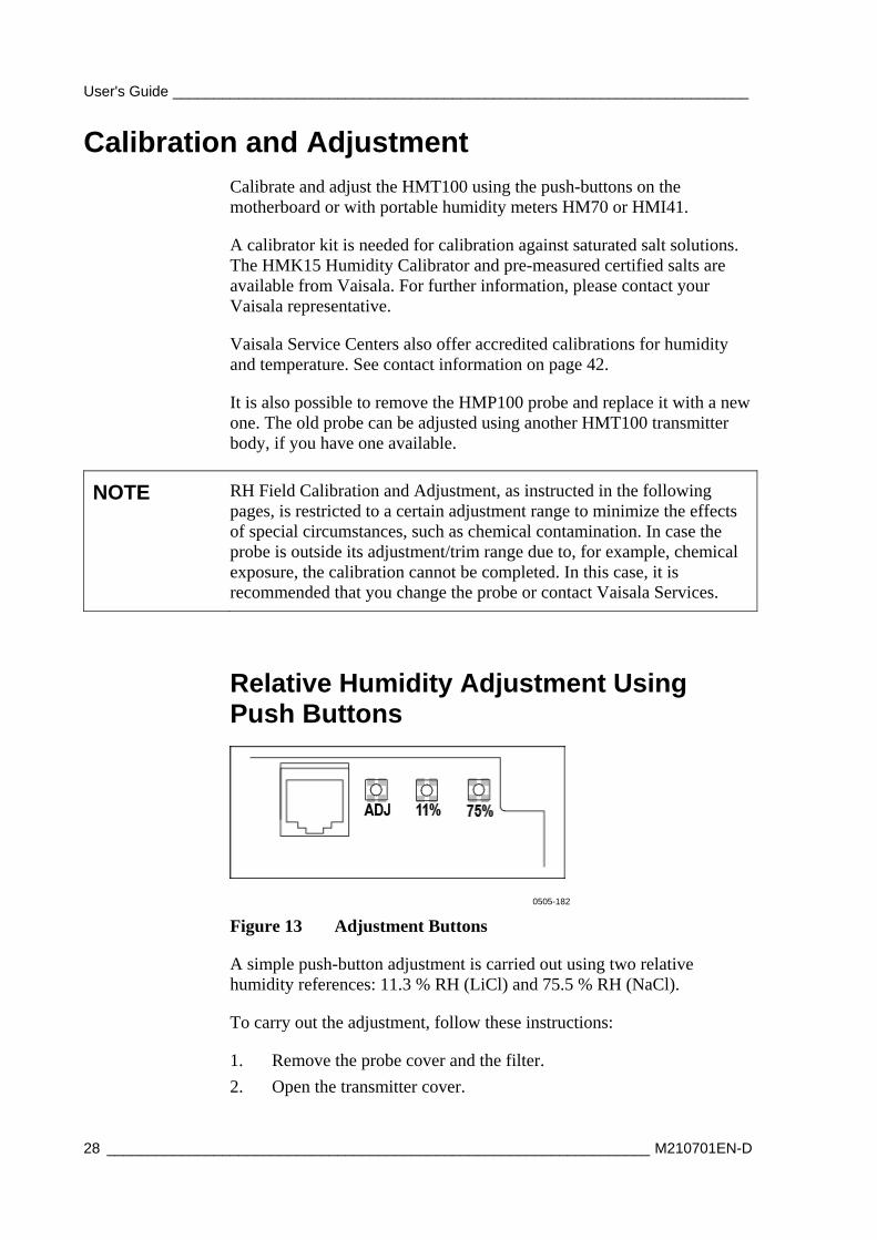
Figure 13 Adjustment Buttons
A simple push-button adjustment is carried out using two relative humidity references: 11.3 % RH (LiCl) and 75.5 % RH (NaCl).
To carry out the adjustment, follow these instructions:
1. Remove the probe cover and the filter.
2. Open the transmitter cover.

Chapter 4 ______________________________________________________________ Maintenance
VAISALA _______________________________________________________________________ 29
3. Press the ADJ button on the transmitter motherboard. An indicator LED lights up.
4. Insert the probe into the measurement hole of the LiCl salt chamber. The indicator LED blinks evenly, indicating that the measurement is changing.
5. Wait for 30 minutes or until the indicator LED stops blinking and is lit continuously, which means that the measurement has stabilized.
6. Press the LiCl 11 % button to adjust the 11 % RH condition. The transmitter returns to the normal operation mode, and the indicator LED turns off.
7. To start calibrating the 75 % RH condition, press the ADJ button on the transmitter motherboard again. The indicator LED lights up.
8. Insert the probe into the measurement hole of the NaCl salt chamber. The indicator LED starts blinking.
9. Wait for 30 minutes or until the indicator LED stops blinking and is lit continuously.
10. Press the NaCl 75 % button to adjust the 75 % RH condition. The transmitter returns to the normal operation mode, and the indicator LED turns off.
11. Replace the filter and the probe cover.
Adjustment with HM70
You can check and adjust the HMT100 relative humidity measurement with the HM70 Hand-Held Humidity and Temperature meter. A HM70-connection cable is needed. Vaisala order code: 211339.
There are four types of adjustments available: field checking and adjustment using a calibrated reference probe, one-point adjustment using a calibrator, two-point adjustment using a calibrator, and LiCl-NaCl adjustment.
Follow the first seven steps and continue according to the chosen adjustment method.
0505-351
Figure 14 Location of the MI70 Probe and Cable Connector Ports
User's Guide ______________________________________________________________________
30 __________________________________________________________________ M210701EN-D
1. Connect the 211339 HM70-connection cable to the SERVICE PORT connector on the HMT100 motherboard (see Figure 9 on page 22).
2. Connect the other end of the connection cable to either of the HM70's connector ports located on the bottom of the indicator (see Figure 14 above).
3. Turn on both devices (or just HM70, in case that HMT100 is on continuously).
4. The reading of the transmitter is shown on the top or middle row of the indicator display, depending on which connector port the connection cable is connected to.
5. Press the ADJ button on the HMT100 motherboard to open the adjustment mode. The indicator LED on the HMT100 motherboard starts flashing.
NOTE From this point onward, the adjustment is carried out using the MI70 indicator. When operating the MI70, do not press the buttons too quickly or the calibration may fail. Wait for one second between each press.
6. Press OK to start adjustment.
7. Check the environment settings if needed. Otherwise, press NO. Select RH or T adjustment. Continue according to the directions of the desired adjustment method.
Field Checking and Adjustment Using a Calibrated Reference Probe
Follow steps 1 to 7 on page 30 and continue as follows:
8. Check that the probes are located in equal conditions and wait until the readings have stabilized (may take 30 minutes or more). If you are close to the probes, do not breath in their direction.
9. Press ADJUST to continue adjusting.
10. Choose To same as RHI/II from the MI70 adjustment menu, press SELECT (MI70 automatically recognizes which port the HMP70 series probe is connected to).
11. Confirm the adjustment by pressing YES.
12. The adjustment is done. Press BACK and EXIT to return to the basic display.
13. Turn off the MI70 and detach the connection cable.

Chapter 4 ______________________________________________________________ Maintenance
VAISALA _______________________________________________________________________ 31
One-Point Adjustment Using a Calibrator
When adjusting the transmitter in only one reference condition, please take care that the reference condition represents the measuring environment. MI70 indicator is used now only as a terminal for visualizing and setting the transmitter's RH reading.
Follow steps 1 to 7 on page 30 and continue as follows:
8. Remove the filter from the transmitter's probe and insert the probe head into the reference condition.
9. Press ADJUST to continue adjusting.
10. Choose 1-point adjustment from the MI70 adjustment menu and press SELECT.
0505-185
Figure 15 Example of the MI70 Adjustment Menu
11. Press READY when the reading has stabilized in the reference condition (may take 30 minutes or more). You can follow the stabilization from the GRAPH display.
0505-186
Figure 16 Example of the MI70 Adjustment Mode Graph Display
12. Enter the correct reference value with the arrow buttons. Press OK.
13. Confirm the adjustment by pressing YES.
14. The adjustment is done. Press BACK and EXIT to return to the basic display.
15. Turn off the MI70 and detach the connection cable.

User's Guide ______________________________________________________________________
32 __________________________________________________________________ M210701EN-D
Two-Point Adjustment Using a Calibrator
Note that the difference between the two reference humidities must be at least 50 %. MI70 indicator is used now only as a terminal for visualizing and setting the transmitter's RH reading.
Follow steps 1 to 7 on page 30 and continue as follows:
8. Remove the filter from the transmitter's probe and insert the probe head into the lower humidity reference condition.
9. Press ADJUST to continue adjusting.
10. Choose 2-point adjustment from the MI70 adjustment menu and press SELECT.
11. Press READY when the reading has stabilized in the first reference condition (may take 30 minutes or more). You can follow the stabilization from the GRAPH display.
12. Enter the correct reference value in the first condition with the arrow buttons. Press OK.
13. Remove the probe from the first reference condition and insert the probe head into the higher humidity reference condition.
14. Press READY when the reading has stabilized in the second reference condition (may take 30 minutes or more). You can follow the stabilization from the GRAPH display.
15. Enter the correct reference value in the second condition with the arrow buttons. Press OK.
16. Confirm the adjustment by pressing YES (by pressing NO you return to adjustment mode display and no changes are made). If the difference between the two reference conditions is less than 50 %RH, adjustment cannot be done.
17. The adjustment is done. Press BACK and EXIT to return to the basic display.
18. Turn off the MI70 and detach the connection cable.
LiCl-NaCl Adjustment
This adjustment is done using relative humidity references 11.3 % RH (LiCl) and 75.5 % RH (NaCl).
Follow steps 1 to 7 on page 30 and continue as follows:
8. Remove the filter from the transmitter's probe and insert the probe head into the LiCl salt chamber.
9. Press ADJUST to continue adjusting.
Chapter 4 ______________________________________________________________ Maintenance
VAISALA _______________________________________________________________________ 33
10. Choose LiCl-NaCl autom. from the MI70 adjustment menu and press SELECT. Press OK to accept the note telling about references.
11. Press READY when the reading has stabilized in the LiCl salt chamber (may take 30 minutes or more). You can follow the stabilization from the GRAPH display.
12. Remove the probe from the LiCl salt chamber and insert the probe head into the NaCl salt chamber.
13. Press READY when the reading has stabilized in the NaCl salt chamber (may take 30 minutes or more). You can follow the stabilization from the GRAPH display.
14. Confirm the adjustment by pressing YES (by pressing NO you return to adjustment mode display and no changes are made).
15. The adjustment is done. Press BACK and EXIT to return to the basic display.
16. Turn off the MI70 and detach the connection cable.
Temperature Field Check and Adjustment by Using a Calibrated Reference Probe
Follow steps 1 to 7 on page 30 and continue as follows:
8. Check that the probes are located in equal conditions and wait until the readings are stabilized (can take 30 minutes or more). If you are close to the probes, do not breathe in their direction.
9. Press ADJUST to continue adjusting.
10. Press To same as TII/I, press SELECT. (MI70 always recognizes the port to which the HMP70 series probe is connected).
11. Confirm by pressing YES.
NOTE If the temperature difference between the reference probe and HMT100 is too large, the adjustment cannot be done (HM70 will notify you of this). The available reserve for T adjustment of HMT100 depends on the initial temperature calibration of the unit.
12. Adjustment is done. Press BACK and EXIT to return to the basic display.
13. Switch off the MI70 and detach the calibration cable from MI70 and from the transmitter.
User's Guide ______________________________________________________________________
34 __________________________________________________________________ M210701EN-D
Adjustment with HMI41
You can check and adjust the HMT100 relative humidity measurement with the HMI41 indicator and HMP41/45/46 probes. A HMI41-connection cable is needed. Vaisala order code: 25917ZZ.
There are three adjustment modes available: offset (dry point), gain (wet point), and two-point adjustment. All of these can be performed using the HMI41 either as a reference meter (for example when the transmitter is mounted in an air-conditioning channel) or only as a terminal for visualizing and setting the transmitter's RH reading.
Offset and gain adjustments are performed the same way and differ only in internal calculations. Select offset adjustment when the reference humidity is < 65 %RH and gain adjustment when the reference humidity is ≥ 65 %RH. Two-point adjustment is more accurate, and includes both offset and gain corrections. For performing two-point adjustment, you need two separate measurement points with a difference of at least 50 %RH between them.
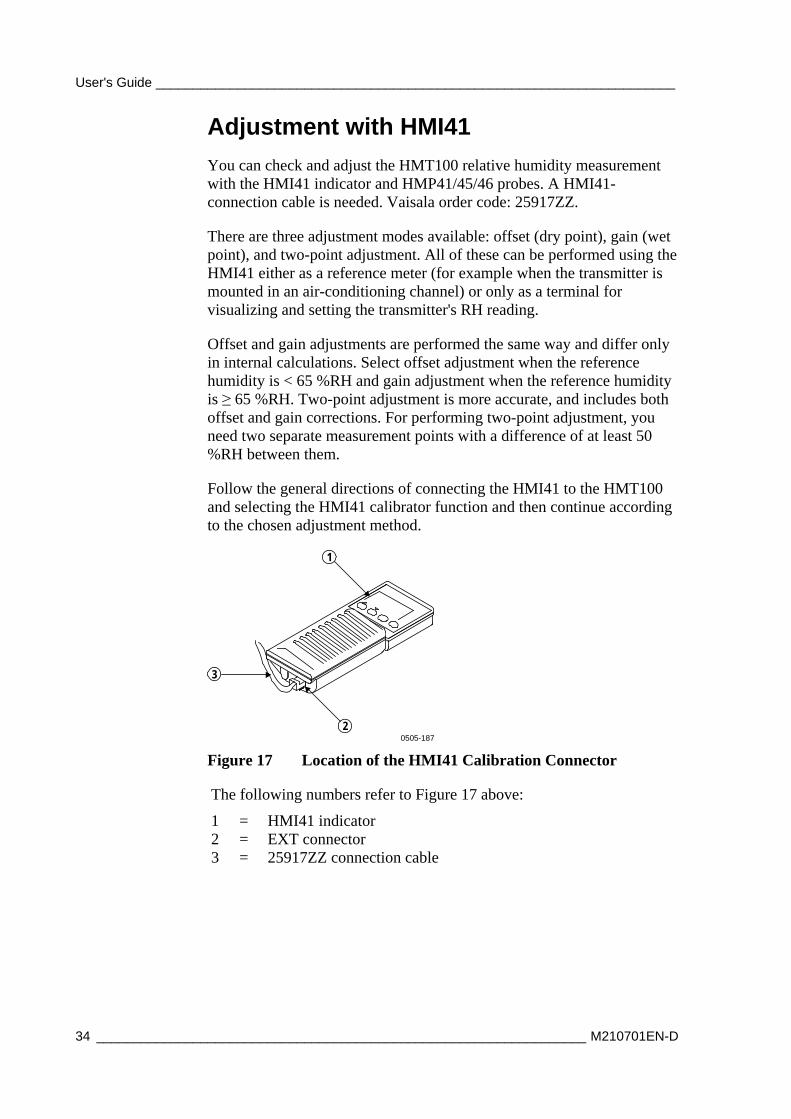
Follow the general directions of connecting the HMI41 to the HMT100 and selecting the HMI41 calibrator function and then continue according to the chosen adjustment method.
1
2
3
0505-187
Figure 17 Location of the HMI41 Calibration Connector
The following numbers refer to Figure 17 above:
1 = HMI41 indicator 2 = EXT connector 3 = 25917ZZ connection cable

Chapter 4 ______________________________________________________________ Maintenance
VAISALA _______________________________________________________________________ 35
Connections and Selecting the Calibrator Function
1. To select the calibrator function from the HMI41, press the ON/OFF button until you can see some text on the display. Then release the ON/OFF button and within 1 ... 2 seconds, press both ENTER and MODE buttons until the following display appears:
2. After a few seconds, the display changes to show the following:
set
°C
If the basic settings (display units, automatic power off function, display quantities, and pressure) have to be changed, please refer to the HMI41 Operating Manual. Otherwise, press ENTER repeatedly until the following display appears:
set
To calibrate the HMT100, select number 3 with buttons (number up) and (number down) and then press ENTER.
3. Next the baud rate appears on the display. Use the baud rate 19200 (= 19.2 on the HMI41 display) with the HMT100 series. If the baud rate on the HMI41 display is not correct, change it with buttons and . When the baud rate is correct, press ENTER, and the serial communications settings display appears. The correct settings for HMT100 series are: N, 8, 1. If needed, change the settings with buttons and until they are correct, press ENTER, and then ON/OFF.
These setting are stored in the HMI41 memory; when the HMI41 is turned on again, it will automatically wake up as a calibrator for digital transmitters with these serial line settings. After making these settings, continue with the adjustment and follow the directions of the chosen adjustment method.
User's Guide ______________________________________________________________________
36 __________________________________________________________________ M210701EN-D
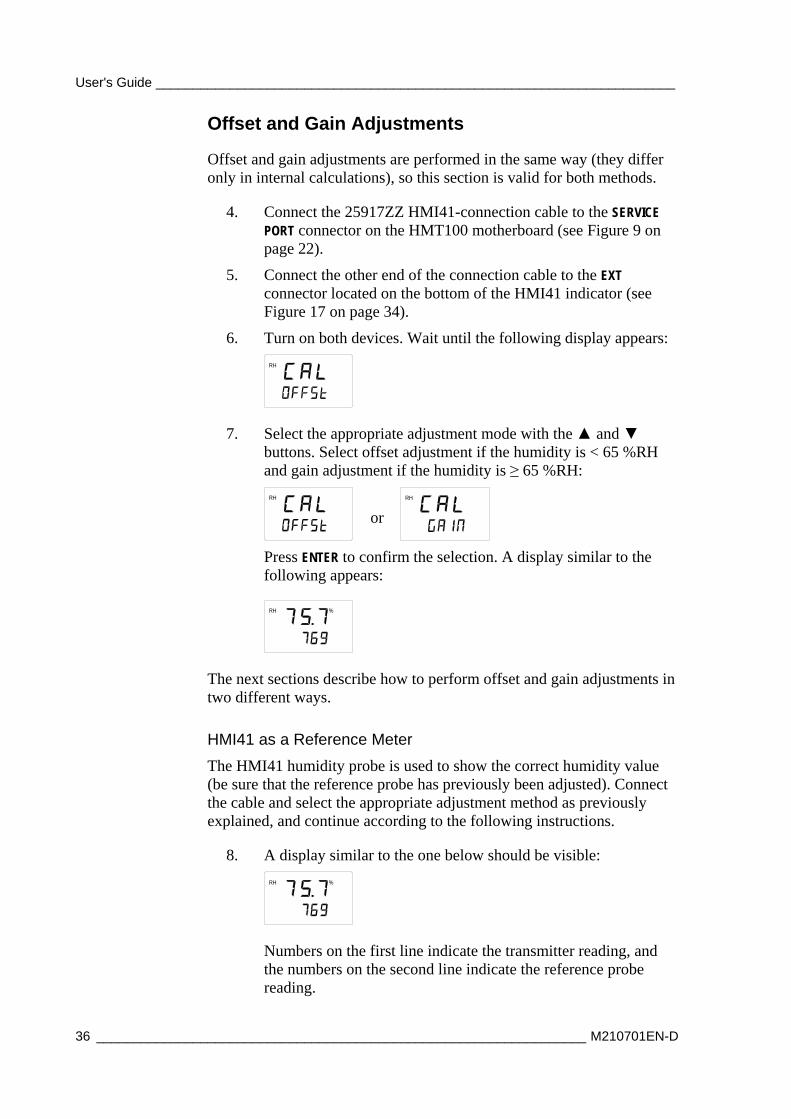
Offset and Gain Adjustments
Offset and gain adjustments are performed in the same way (they differ only in internal calculations), so this section is valid for both methods.
4. Connect the 25917ZZ HMI41-connection cable to the SERVICE PORT connector on the HMT100 motherboard (see Figure 9 on page 22).
5. Connect the other end of the connection cable to the EXT connector located on the bottom of the HMI41 indicator (see Figure 17 on page 34).
6. Turn on both devices. Wait until the following display appears:
RH
7. Select the appropriate adjustment mode with the and buttons. Select offset adjustment if the humidity is < 65 %RH and gain adjustment if the humidity is ≥ 65 %RH:
RH
or
RH
Press ENTER to confirm the selection. A display similar to the following appears:
RH %
The next sections describe how to perform offset and gain adjustments in two different ways.
HMI41 as a Reference Meter
The HMI41 humidity probe is used to show the correct humidity value (be sure that the reference probe has previously been adjusted). Connect the cable and select the appropriate adjustment method as previously explained, and continue according to the following instructions.
8. A display similar to the one below should be visible:
RH %
Numbers on the first line indicate the transmitter reading, and the numbers on the second line indicate the reference probe reading.

Chapter 4 ______________________________________________________________ Maintenance
VAISALA _______________________________________________________________________ 37
9. Let the readings stabilize (may take 30 minutes or more). If you prefer, you can change the display to show the difference in the readings. Press HOLD and a display similar to the following appears:
RH %
The numbers on the first line indicate how much the transmitter reading differs from that of the HMI41 reference probe. The numbers on the second line indicate the reference probe reading. You can return to the previous display by pressing HOLD again.
10. When the readings have stabilized, press ENTER to conclude the adjustment. When ENTER is pressed, the transmitter reading is corrected to the reference probe reading. If the adjustment has been succesful, the following display appears:
RH
11. The data is now stored in the transmitter memory. If the adjustment has not been succesful, the following display appears:
RH
In this case, perform the adjustment again. Whether the adjustment was succesful or not, the HMI41 always returns to display the selected adjustment mode.
12. After succesfully completing the adjustment, turn off the HMI41 and disconnect the cable.
HMI41 as a Terminal
The HMI41 can also be used for visualizing and setting the transmitter's RH reading manually.
8. A display similar to the one below should be visible:
RH %
The numbers on the first line indicate the transmitter reading, and the numbers on the second line indicate the HMI41 probe reading.
User's Guide ______________________________________________________________________
38 __________________________________________________________________ M210701EN-D
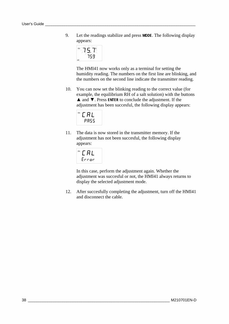
9. Let the readings stabilize and press MODE. The following display appears:
RH
set
%
The HMI41 now works only as a terminal for setting the humidity reading. The numbers on the first line are blinking, and the numbers on the second line indicate the transmitter reading.
10. You can now set the blinking reading to the correct value (for example, the equilibrium RH of a salt solution) with the buttons and . Press ENTER to conclude the adjustment. If the adjustment has been succesful, the following display appears:
RH
11. The data is now stored in the transmitter memory. If the adjustment has not been succesful, the following display appears:
RH
In this case, perform the adjustment again. Whether the adjustment was succesful or not, the HMI41 always returns to display the selected adjustment mode.
12. After succesfully completing the adjustment, turn off the HMI41 and disconnect the cable.
Chapter 4 ______________________________________________________________ Maintenance
VAISALA _______________________________________________________________________ 39
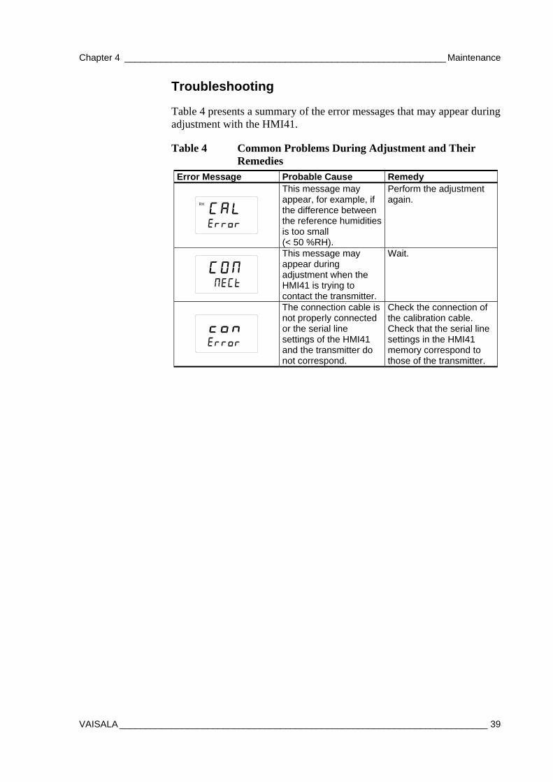
Troubleshooting
Table 4 presents a summary of the error messages that may appear during adjustment with the HMI41.
Table 4 Common Problems During Adjustment and Their Remedies
Error Message Probable Cause Remedy
RH
This message may appear, for example, if the difference between the reference humidities is too small (< 50 %RH).
Perform the adjustment again.
This message may appear during adjustment when the HMI41 is trying to contact the transmitter.
Wait.
The connection cable is not properly connected or the serial line settings of the HMI41 and the transmitter do not correspond.
Check the connection of the calibration cable. Check that the serial line settings in the HMI41 memory correspond to those of the transmitter.
User's Guide ______________________________________________________________________
40 __________________________________________________________________ M210701EN-D
Analog Output Tests HMT100 has a built-in software function for testing the analog outputs. To test the outputs, do the following:
1. Make sure the transmitter is not in adjustment mode.
2. Press the 75 % adjustment button (see Figure 13 on page 28).
This sets the output current/voltage level to the middle point of the selected output range (specified when ordering the product). The output stays at this level for about 30 seconds after the 75 % adjustment button has been pressed.
Examples:
If you have specified 4 ... 20 mA analog output range, pressing the 75 % adjustment button will set the current output at 12.0 mA for about 30 seconds.
For analog output range 0 … 1 V, pressing the 75 % adjustment button will set the voltage output at 0.5 V for about 30 seconds.
Chapter 5 ___________________________________________________________ Troubleshooting
VAISALA _______________________________________________________________________ 41
CHAPTER 5
TROUBLESHOOTING
This chapter describes error messages and provides contact information for Technical Support and Vaisala Service Centers.
Error Mode
Current Output
In error mode the analog outputs switch to IOUT = 23 mA. Error mode indication covers only transmitter body electronic functions. The transmitter cannot indicate a faulty RH probe.
Voltage Output
Voltage output version has no error mode indication.
Technical Support For technical questions, contact the Vaisala technical support:
E-mail [email protected]
Fax +358 9 8949 2790

User's Guide ______________________________________________________________________
42 __________________________________________________________________ M210701EN-D
Return Instructions If the product needs repair, please follow the instructions below to speed up the process and to avoid extra costs to you.
1. Read the section Warranty on page 9.
2. Contact a Vaisala Service Center or a local Vaisala representative. The latest contact information and instructions are available from www.vaisala.com. Addresses of the Service Centers are provided on page 43. Please have the following information on hand:
- serial number of the unit
- date and place of purchase or last calibration
- description of the fault
- circumstances in which the fault occurs/occurred
- name and contact information of a technically competent person who can provide further information on the problem
3. Pack the faulty product in a strong box of adequate size, with proper cushioning material to avoid damage.
4. Include the information specified in step 2 in the box with the faulty product. Include a detailed return address as well.
5. Ship the box to the address specified by your Vaisala contact.
Chapter 5 ___________________________________________________________ Troubleshooting
VAISALA _______________________________________________________________________ 43
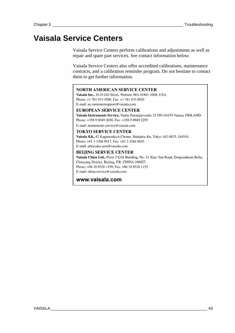
Vaisala Service Centers Vaisala Service Centers perform calibrations and adjustments as well as repair and spare part services. See contact information below.
Vaisala Service Centers also offer accredited calibrations, maintenance contracts, and a calibration reminder program. Do not hesitate to contact them to get further information.

User's Guide ______________________________________________________________________
44 __________________________________________________________________ M210701EN-D
This page intentionally left blank.
Chapter 6 ____________________________________________________________ Technical Data
VAISALA _______________________________________________________________________ 45
CHAPTER 6
TECHNICAL DATA
This chapter provides the technical data of the product.
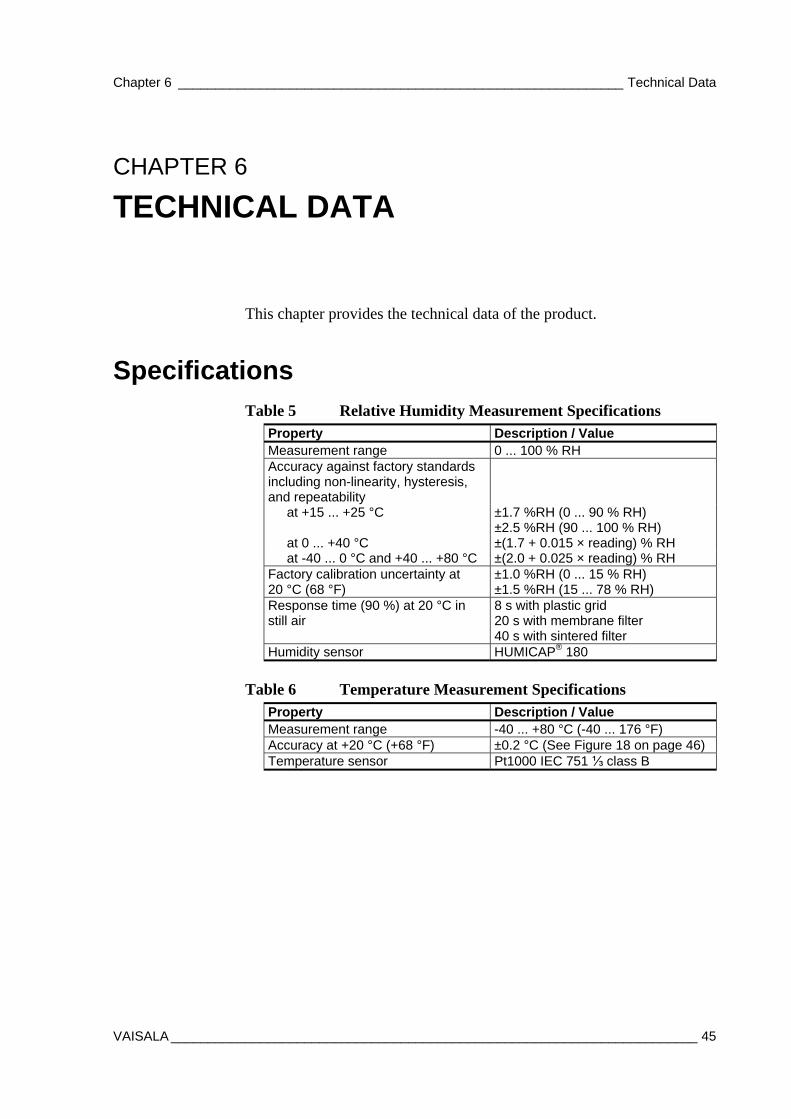
Specifications Table 5 Relative Humidity Measurement Specifications
Property Description / Value Measurement range 0 ... 100 % RH Accuracy against factory standards including non-linearity, hysteresis, and repeatability
at +15 ... +25 °C ±1.7 %RH (0 ... 90 % RH) ±2.5 %RH (90 ... 100 % RH)
at 0 ... +40 °C ±(1.7 + 0.015 × reading) % RH at -40 ... 0 °C and +40 ... +80 °C ±(2.0 + 0.025 × reading) % RH
Factory calibration uncertainty at 20 °C (68 °F)
±1.0 %RH (0 ... 15 % RH) ±1.5 %RH (15 ... 78 % RH)
Response time (90 %) at 20 °C in still air
8 s with plastic grid 20 s with membrane filter 40 s with sintered filter
Humidity sensor HUMICAP® 180
Table 6 Temperature Measurement Specifications
Property Description / Value Measurement range -40 ... +80 °C (-40 ... 176 °F) Accuracy at +20 °C (+68 °F) ±0.2 °C (See Figure 18 on page 46) Temperature sensor Pt1000 IEC 751 ⅓ class B

User's Guide ______________________________________________________________________
46 __________________________________________________________________ M210701EN-D
0505-247
Figure 18 Accuracy of Temperature Measurement
Table 7 Dewpoint Temperature (Calculated) Measurement Specifications
Property Description / Value Measuring range -20 ... +80 °C (+4 ... 176 °F) Accuracy see Table 8 below
Table 8 Accuracy of Dewpoint Temperature Measurement Relative humidity Temp. 10 20 30 40 50 60 70 80 90 100 -20 2.6 1.7 1.4 1.2 1.1 1.1 1.0 1.0 -10 2.7 1.7 1.3 1.2 1.1 1.0 1.0 1.0 0.9 0 2.3 1.4 1.1 1.0 0.9 0.8 0.8 0.8 0.7 0.7 10 2.3 1.4 1.1 0.9 0.8 0.9 0.8 0.8 0.8 0.8 20 2.2 1.2 1.0 0.8 0.7 0.6 0.6 0.5 0.5 0.6 40 3.0 1.9 1.5 1.3 1.2 1.1 1.0 1.0 1.0 1.0 60 4.3 2.7 2.2 1.9 1.8 1.7 1.6 1.5 1.5 1.5 80 4.9 3.1 2.5 2.2 2.1 2.0 1.9 1.8 1.8 1.8
Table 9 Operating Environment Specifications Property Description / Value Operating temperature range
Transmitter body, no display Transmitter body, with display Sensor head
-40 ... +60 °C (-40 ... +140 °F) -30 ... +60 °C (-22 ... +140 °F) -40 ... +80 °C (-40 ... +176 °F)
Storage temperature range -40 ... +60 °C (-40 ... +140 °F) Electromagnetic compatibility EN61326-1:1197+Am1:1998; +
Am2:2001; Generic Environment
Chapter 6 ____________________________________________________________ Technical Data
VAISALA _______________________________________________________________________ 47
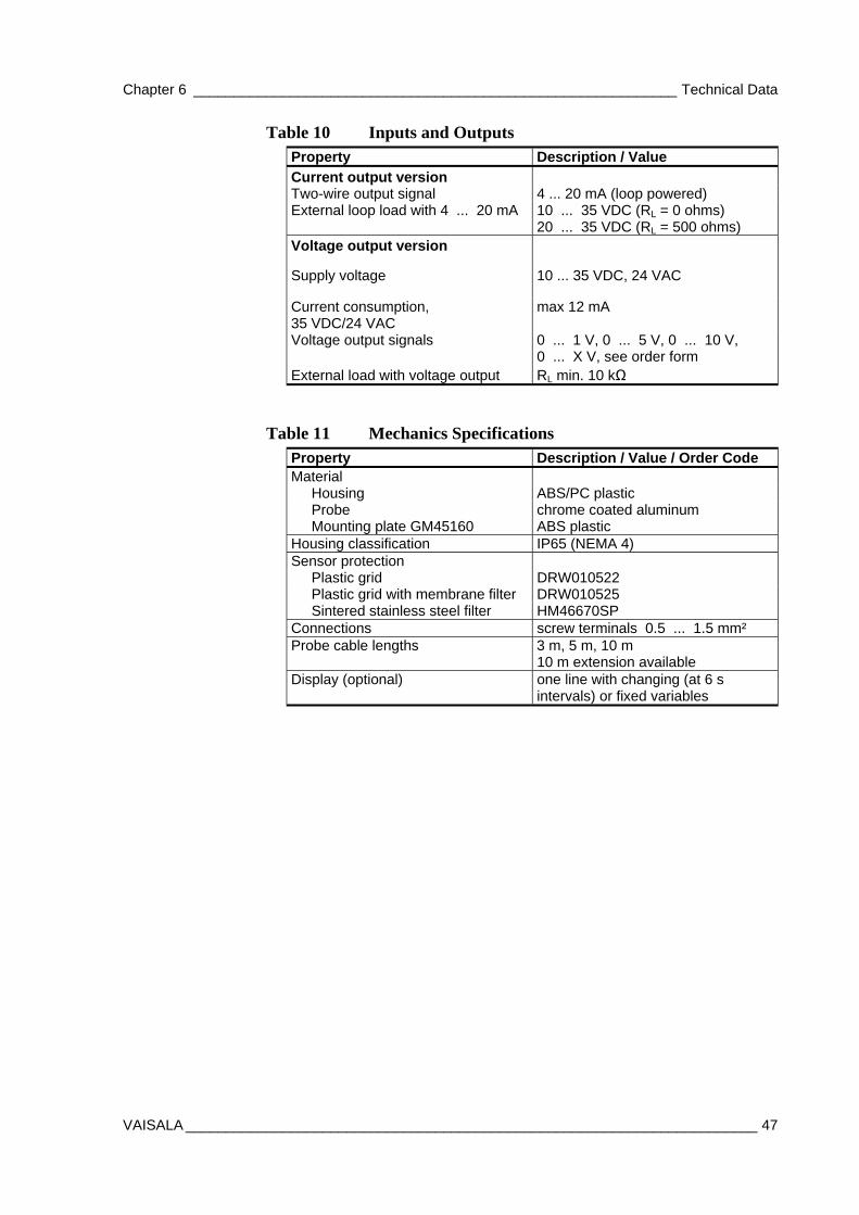
Table 10 Inputs and Outputs Property Description / Value
Current output version Two-wire output signal 4 ... 20 mA (loop powered) External loop load with 4 ... 20 mA 10 ... 35 VDC (RL = 0 ohms)
20 ... 35 VDC (RL = 500 ohms) Voltage output version
Supply voltage 10 ... 35 VDC, 24 VAC
Current consumption, 35 VDC/24 VAC
max 12 mA
Voltage output signals 0 ... 1 V, 0 ... 5 V, 0 ... 10 V, 0 ... X V, see order form
External load with voltage output RL min. 10 kΩ
Table 11 Mechanics Specifications Property Description / Value / Order Code Material
Housing ABS/PC plastic Probe chrome coated aluminum Mounting plate GM45160 ABS plastic
Housing classification IP65 (NEMA 4) Sensor protection
Plastic grid DRW010522 Plastic grid with membrane filter DRW010525 Sintered stainless steel filter HM46670SP
Connections screw terminals 0.5 ... 1.5 mm² Probe cable lengths 3 m, 5 m, 10 m
10 m extension available Display (optional) one line with changing (at 6 s
intervals) or fixed variables

User's Guide ______________________________________________________________________
48 __________________________________________________________________ M210701EN-D
Table 12 Options and Accessories Description Order Code Sensor head HMP100 HMP100 Humidity sensor Humicap180 T-sensor PT1000 18921 Filter plastic grid + membrane DRW010525 Sintered stainless steel filter HM46670SP Extension cable 10 m DRW220095 Probe cable 0.1 m HMP50Z010SP Probe cable 3 m HMP50Z300SP Probe cable 5 m HMP50Z500SP Probe cable 10 m HMP50Z1000SP Radiation shield DTR502B Rain shield with installation kit 215109 Probe holder 215986 Duct installation kit 215619 Wall assembly plate (plastic) GM45160 Installation plate (aluminum) DRW010712 Probe cover (protective cap used with fixed probe)
HM47329
Casing for probe HM47328 HMI41 connection cable 25917ZZ HM70 connection cable 211339

Chapter 6 ____________________________________________________________ Technical Data
VAISALA _______________________________________________________________________ 49
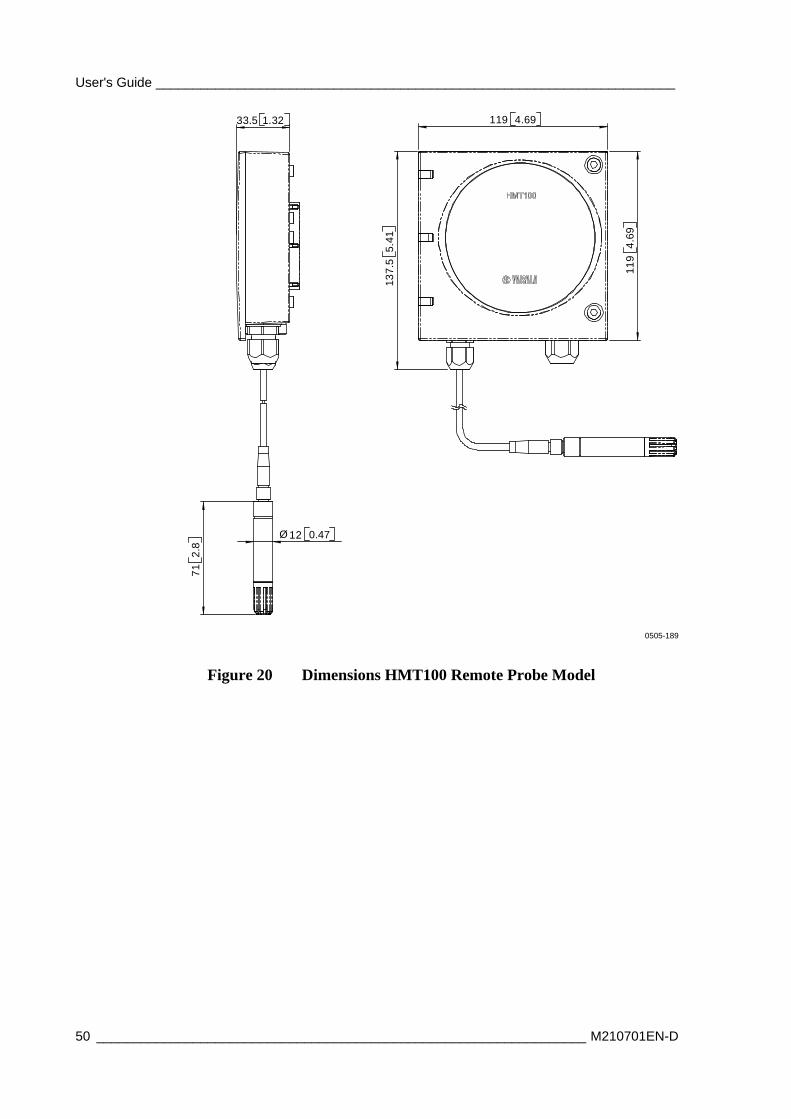
Dimensions in mm (inches)
0505-188
Figure 19 Dimensions HMT100 Fixed Probe Model
User's Guide ______________________________________________________________________
50 __________________________________________________________________ M210701EN-D
Ø12 0.47
712.
8
137.
55.
41
33.5 1.32 119 4.69
119
4.69
0505-189
Figure 20 Dimensions HMT100 Remote Probe Model

____________________________________________________________________ Technical Data
VAISALA _______________________________________________________________________ 51

www.vaisala.com
*M210701EN*


![10.1” Tablet PC User's Guide [ English ]€ Tablet PC User's Guide [ English ] TABLE OF CONTENTS ‧Notice ‧Preface 1.1 Notes for this Manual 1.2 For Your Records ‧Getting to](https://static.fdocuments.in/doc/165x107/5accb6e87f8b9a6a678c9c2d/101-tablet-pc-users-guide-english-tablet-pc-users-guide-english-.jpg)


![10.1” Tablet PC User's Guide [ English ]](https://static.fdocuments.in/doc/165x107/6169ede211a7b741a34ceedd/101-tablet-pc-users-guide-english-.jpg)


